stepper motor driver - nippon pulse user's manua… · stepper motor driver ad1431 ya7179-1/0...
TRANSCRIPT

YA7179-1/0
Stepper Motor Driver
Preliminary
Nippon Pulse Motor Co., Ltd
Stepper Motor Driver AD1431 YA7179-1/0
- C1 -
Table of Contents
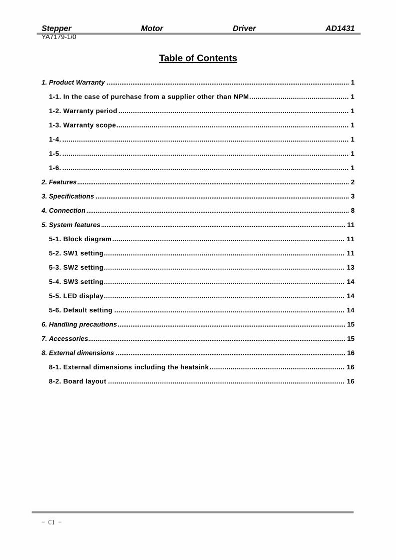
1. Product Warranty .................................................................................................................................... 1
1-1. In the case of purchase from a supplier other than NPM ................................................ 1
1-2. Warranty period ............................................................................................................... 1
1-3. Warranty scope ................................................................................................................ 1
1-4. .......................................................................................................................................... 1
1-5. .......................................................................................................................................... 1
1-6. .......................................................................................................................................... 1
2. Features .................................................................................................................................................... 2
3. Specifications .......................................................................................................................................... 3
4. Connection ............................................................................................................................................... 8
5. System features ..................................................................................................................................... 11
5-1. Block diagram ................................................................................................................ 11
5-2. SW1 setting .................................................................................................................... 11
5-3. SW2 setting .................................................................................................................... 13
5-4. SW3 setting .................................................................................................................... 14
5-5. LED display .................................................................................................................... 14
5-6. Default setting ............................................................................................................... 14
6. Handling precautions ............................................................................................................................ 15
7. Accessories............................................................................................................................................ 15
8. External dimensions ............................................................................................................................. 16
8-1. External dimensions including the heatsink ................................................................. 16
8-2. Board layout .................................................................................................................. 16

Stepper Motor Driver AD1431 YA7179-1/0
- 1 -
1. Product Warranty
1-1. In the case of purchase from a supplier other than NPM Regarding the product warranty in the case of purchase from a supplier other than NPM, please contact to the supplier
1-2. Warranty period The warranty period is one year from the date of the delivery to an assigned place.
1-3. Warranty scope If defects are found in the product during the warranty period under normal use following this document, NPM will repair the product without charge. However, the following cases are not covered by the warranty and free repair does not apply to the product even during the warranty period. - The products are modified or repaired by anyone other than NPM or an authorized person by NPM. - The defect results from falling of the product after delivery or mishandling in transit. - -Wearing of components, natural deterioration or fatigue (motor axle bearing, gear, grease, cables,
etc.) - The defect results from any use other than original use. - The product has been subjected to natural disaster or force majeure such as fire, earthquake,
lightning strike, wind and flood, salt, and electrical surges. - The defects or damage results from the cause other than the fault of NPM.
Note 1) The products exported to outside Japan are not covered by the warranty. Note 2) Only if the product with defects is carried to the specific place to repair, NPM will repair the
product. NPM will not provide on-site repair. Note 3) The warranty period of the repaired product is not extended beyond the warranty period of the
product before the failure. It is the same as the warranty product of the product before the repair. Note 4) This warranty covers the product. It does not cover the detriments caused by the product's
defects, etc. Note 5) A replacement may be provided instead of a repair at the direction of NPM.
1-4. This documents aims to describe the detail of the function of the product and it does not warrant fitness for a particular purpose of the customers. The examples of application and circuit diagram in this manual are described for your reference. Please confirm the feature and the safety of device or equipment before use.
1-5. Please do not use this product for the following use in principle. If you use the product for the following use, please contact our sales department.
- Any equipment that may require high reliability or safety, such as nuclear facility, electricity or gas supply system, transportation facilities, vehicle, various safety system, medical equipment, etc.
- Any equipment that may directly affect human survival or property - Usage under conditions or circumstances that are not specified in the brochure, manual, etc.
1-6. When this product is used in any equipment where faults or malfunctions may directly affect human survival or property, please secure high reliability and security with redundancy design, etc.
Stepper Motor Driver AD1431 YA7179-1/0
- 2 -
2. Features
AD1431 is a constant current stepper motor driver of 2 phase bipolar type. - It drives a bipolar motor. - Output current can be set by a rotary switch easily. - It has auto current down function to prevent heat generation during the motor stopping. - Excitation method can be selected from among 2-phase, 1-2 phase, W1-2 and 4W1-2 phase excitation
by a switch. It can drive a motor with low vibration. - It fits for an experiment or evaluation as well as for being embedded in devices.

Stepper Motor Driver AD1431 YA7179-1/0
- 3 -
3. Specifications Product Name : Stepper Motor Driver Model : AD1431 Electrical specifications
Input voltage Control power : DC12V -10% to DC24V +10% Capacity: 2A, with fuse.
Control method Bipolar constant current
Excitation method 2 phase (FULL), 1-2 phase (HALF), W1-2 phase (1/4), 4W1-2 phase (1/16)
Output current 0.11A (MIN) to 1.20A (MAX) / phase Selectable by the rotary switch.
Auto current down (ACD) control *1
Current down operation starts in approximately 0.1s after pulse input stops and lowers the output current automatically. Selectable from 25%, 50% or 75% of the current by using the switch.
Input interface Pins 1 to 4 of CN2: Photocoupler (Toshiba TLP109 or equivalent)
Built-in 300 ohm resistor Forward voltage 1.64V (TYP) Recommended forward current IF:11mA (Operation forward current IF:10 to 20mA) Maximum response frequency 160kpps (Input voltage 5V, duty rate 50%)
Pins 5 to 8 of CN2 : Photocoupler (Toshiba TLP281 or equivalent)
Built-in 330 ohm resistor Forward voltage 1.15V (TYP) Recommended forward current IF:12mA (Operation forward current IF:5 to 50mA)
Output interface Pins 9 to 10 of CN2: Photocoupler (Toshiba TLP281 or equivalent)
Recommended collector current Ic: 10mA (Saturation voltage between collector and emitter : 0.7V)
CW/CCW command pulse
One of the following methods can be selected by the switch. *2 1. Two pulse method (CW/CCW) 2. One pulse method (CLK/DIR)
Photocoupler ON: CCW Photocoupler OFF : CW
MOT/OFF signals Motor excitation signal Photocoupler ON : Excitation OFF Photocoupler OFF : Excitation ON
ACD/OFF signals Auto current down signal Photocoupler ON : ACD_OFF Photocoupler OFF : ACD_ON
EORG output signals
Display signal of initial excitation condition *3 Photocoupler ON : Initial excitation Photocoupler OFF: other than initial excitation
Stepper Motor Driver AD1431 YA7179-1/0
- 4 -
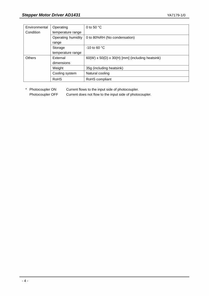
Environmental Condition
Operating temperature range
0 to 50 °C
Operating humidity range
0 to 80%RH (No condensation)
Storage temperature range
-10 to 60 °C
Others External dimensions
60(W) x 50(D) x 30(H) [mm] (including heatsink)
Weight 35g (including heatsink) Cooling system Natural cooling
RoHS RoHS compliant * Photocoupler ON Current flows to the input side of photocoupler. Photocoupler OFF Current does not flow to the input side of photocoupler.

Stepper Motor Driver AD1431 YA7179-1/0
- 5 -
*1 Auto current down Auto current down is a function to prevent heat generation by adjusting to set lower current after pulse signals stop. This driver allows to lower the current to 25%, 50% and 75% of the normal current to drive the motor.
*2 One pulse mode and two pulse mode
One pulse mode It is a method that the rotation direction CW/CCW is decided by whether the DIR photocoupler is ON or OFF when pulses are input to the CLK terminal.
Two pulse mode
It is a method that the rotation direction CW/CCW is decided by whether the pulse is input to the CW terminal or that CCW terminal.
In the case that CLK(+) and DIR(+) are connected to +5V.
In the case that CW(+) and CCW(+) are connected to +5V.
CCW(-)
Motor stops CCW rotation
Motor stops CW rotation
Rotation direction
CW(-)
Longer than 2 μs
OFF
ON
OFF
ON
+5V CW(+)
CW(-)
CCW(+)
CCW(-)
AD1431
DIR(-)
Motor stops CCW rotation
Motor stops CW rotation
Rotation direction
CLK(-)
Longer than 1 μs
Longer than 1 μs
OFF
ON
OFF
ON
+5V CLK(+)
CLK(-)
DIR(+)
DIR(-)
AD1431
Stepper Motor Driver AD1431 YA7179-1/0
- 6 -
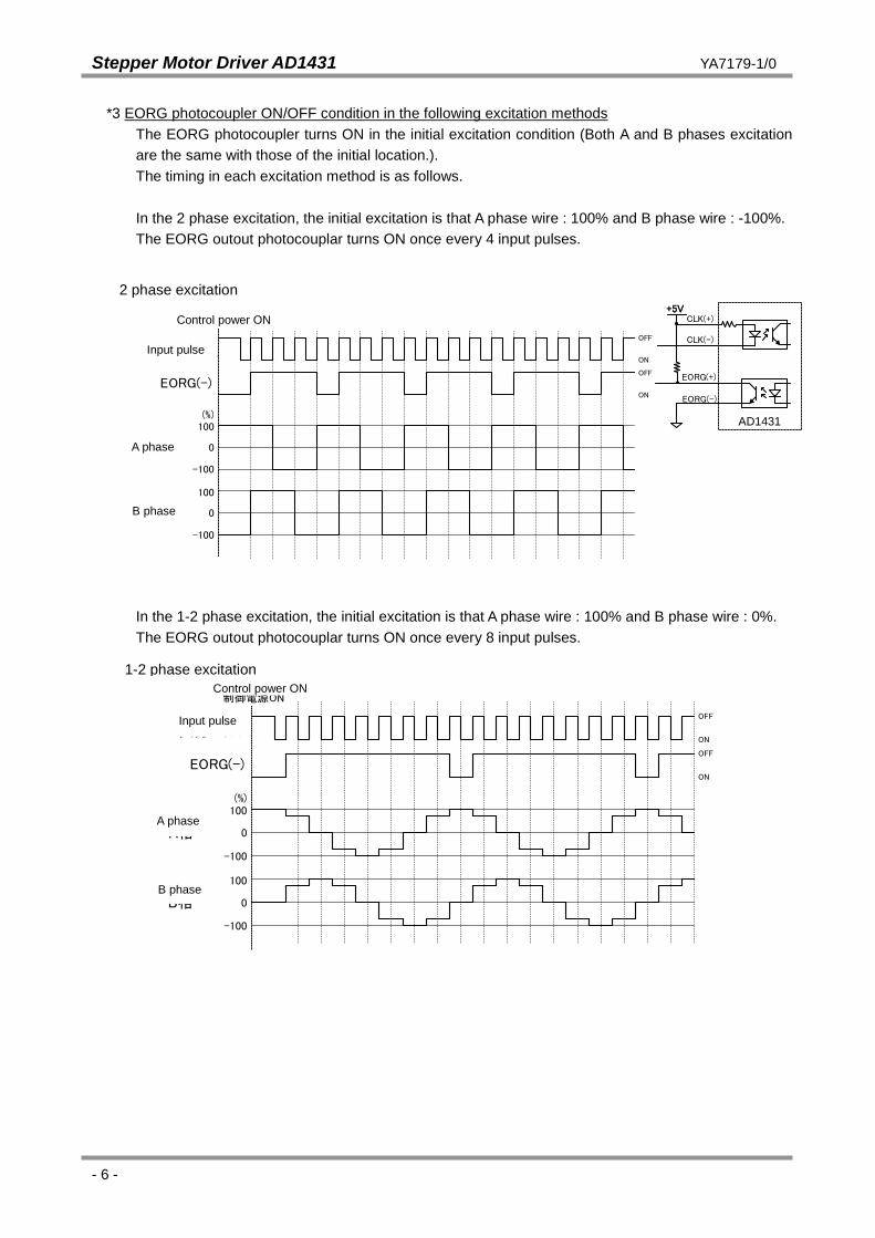
*3 EORG photocoupler ON/OFF condition in the following excitation methods The EORG photocoupler turns ON in the initial excitation condition (Both A and B phases excitation are the same with those of the initial location.). The timing in each excitation method is as follows. In the 2 phase excitation, the initial excitation is that A phase wire : 100% and B phase wire : -100%. The EORG outout photocouplar turns ON once every 4 input pulses.
2相励磁
EORG(-)
制御電源ON
入力パルス
+5V
OFF
ON
OFF
ON
A相 0
100
-100
(%)
B相 0
100
-100
+5VCLK(+)
CLK(-)
EORG(+)
EORG(-)
AD1431側
In the 1-2 phase excitation, the initial excitation is that A phase wire : 100% and B phase wire : 0%. The EORG outout photocouplar turns ON once every 8 input pulses.
1-2相励磁
EORG(-)
制御電源ON
入力パルスOFF
OFF
ON
A相 0
100
-100
(%)
B相 0
100
-100
ON
AD1431
2 phase excitation
Control power ON
Input pulse
A phase
B phase
B phase
A phase
Input pulse
Control power ON 2 1-2 phase excitation
Stepper Motor Driver AD1431 YA7179-1/0
- 7 -
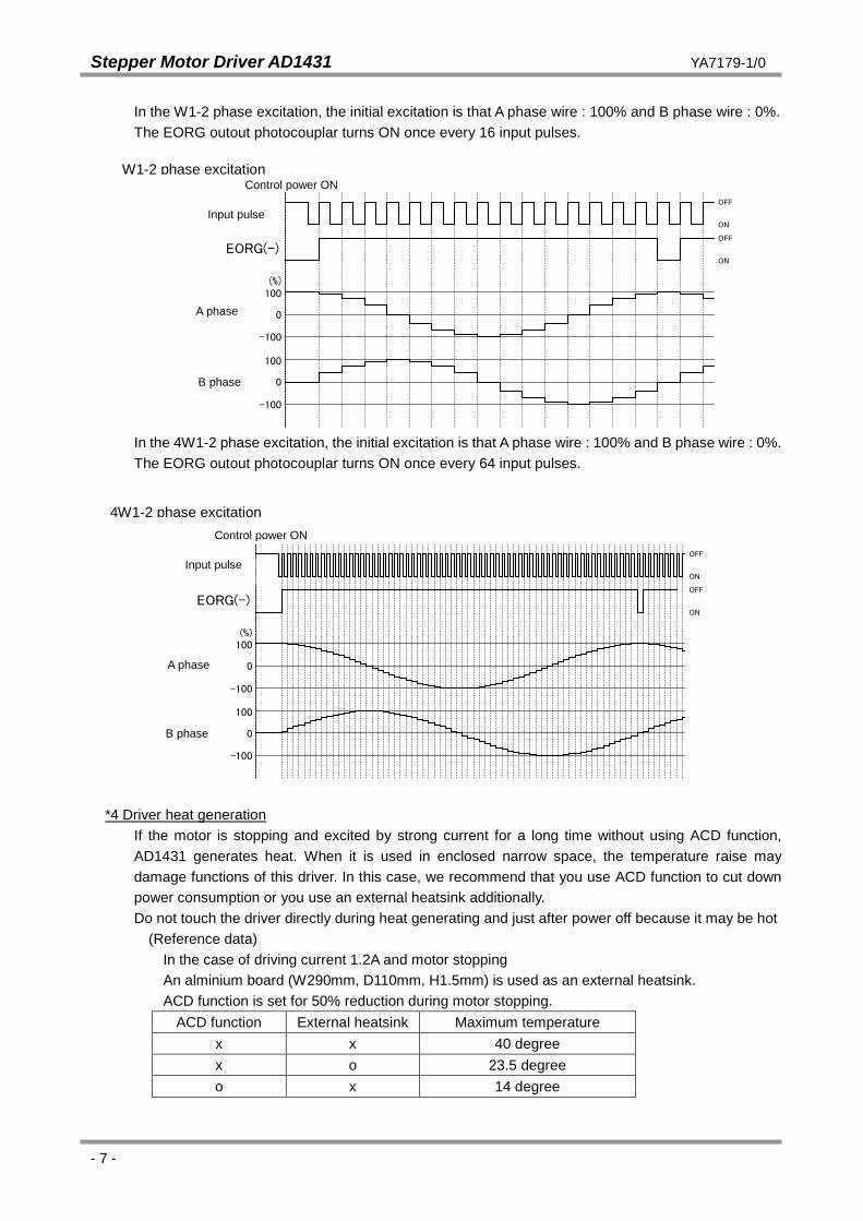
In the W1-2 phase excitation, the initial excitation is that A phase wire : 100% and B phase wire : 0%. The EORG outout photocouplar turns ON once every 16 input pulses.
W1-2相励磁
EORG(-)
制御電源ON
入力パルスOFF
OFF
ON
A相 0
100
-100
(%)
B相 0
100
-100
ON
In the 4W1-2 phase excitation, the initial excitation is that A phase wire : 100% and B phase wire : 0%. The EORG outout photocouplar turns ON once every 64 input pulses.
4W1-2相励磁
EORG(-)
制御電源ON
入力パルスOFF
OFF
ON
A相 0
100
-100
(%)
B相 0
100
-100
ON
*4 Driver heat generation
If the motor is stopping and excited by strong current for a long time without using ACD function, AD1431 generates heat. When it is used in enclosed narrow space, the temperature raise may damage functions of this driver. In this case, we recommend that you use ACD function to cut down power consumption or you use an external heatsink additionally. Do not touch the driver directly during heat generating and just after power off because it may be hot
(Reference data) In the case of driving current 1.2A and motor stopping An alminium board (W290mm, D110mm, H1.5mm) is used as an external heatsink. ACD function is set for 50% reduction during motor stopping.
ACD function External heatsink Maximum temperature x x 40 degree x o 23.5 degree o x 14 degree
W1-2 phase excitation 2 Control power ON
Input pulse
A phase
B phase
2 phase i i
4W1-2 phase excitation Control power ON
Input pulse
A phase
B phase
ControN
Stepper Motor Driver AD1431 YA7179-1/0
- 8 -
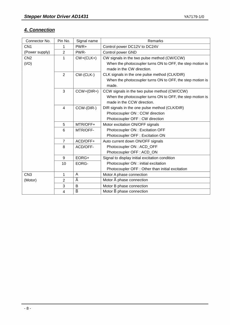
4. Connection
Connector No. Pin No. Signal name Remarks CN1 (Power supply)
1 PWR+ Control power DC12V to DC24V 2 PWR- Control power GND
CN2 (I/O)
1 CW+(CLK+)
CW signals in the two pulse method (CW/CCW) When the photocoupler turns ON to OFF, the step motion is made in the CW direction.
CLK signals in the one pulse method (CLK/DIR) When the photocoupler turns ON to OFF, the step motion is made.
2 CW-(CLK-)
3 CCW+(DIR+)
CCW signals in the two pulse method (CW/CCW) When the photocoupler turns ON to OFF, the step motion is made in the CCW direction.
DIR signals in the one pulse method (CLK/DIR) Photocoupler ON : CCW direction Photocoupler OFF : CW direction
4 CCW-(DIR-)
5 MTR/OFF+ Motor excitation ON/OFF signals Photocoupler ON : Excitation OFF Photocoupler OFF : Excitation ON
6 MTR/OFF-
7 ACD/OFF+ Auto current down ON/OFF signals Photocoupler ON : ACD_OFF Photocoupler OFF : ACD_ON
8 ACD/OFF-
9 EORG+ Signal to display initial excitation condition Photocoupler ON : initial excitation Photocoupler OFF : Other than initial excitation
10 EORG-
CN3 (Motor)
1 A Motor A phase connection 2
_A Motor
_A phase connection
3 B Motor B phase connection 4
_B Motor
_B phase connection

Stepper Motor Driver AD1431 YA7179-1/0
- 9 -
Connection example of CN2 Input/output interface
User controller AD1431
OFF
ON
When photocoupler is ON, the LED lights
Input signal
Forward current IF 5V
330
5V
GND
Pin 9 of CN2
Pin 10 of CN2
Pins 2, 4, 6 and 8 of CN2
Pins 1, 3, 5 and 7 of CN2
Collector current IC

Stepper Motor Driver AD1431 YA7179-1/0
- 10 -
Typical example of connection with driver
ドライバAD1431
1
2
1
2
3
4
5
6
7
8
9
10
1
2
3
4
SW1
SW3
SW2
DC+24V電源
+
-
Motor
VR1
2パルス方式と1パルス方式の変更モータの励磁方式の変更
駆動電流の切替え
カレントダウン時の駆動電流設定
駆動電流の微調整ロータをCW回転で駆動電流上昇
+5V
ユーザコントローラ
PWR+
PWR-
+CW(CLK)
-
+CCW(DIR)
-
+MTR/OFF
-
+ACD/OFF
-
+EORG
-
A
A
B
B
SW1CN1
CN2
CN3
AD1431 driver
DC+24V Power
Switch between two pulse and one pulse method
Change motor excitation method
Switch driving current
Set driving current in current down
Fine adjustment of the driving current (Driving current rises when the rotor is rotated in the CW direction.)
User controller

Stepper Motor Driver AD1431 YA7179-1/0
- 11 -
5. System features
5-1. Block diagram
5-2. SW1 setting SW1 can switch between the two pulse (CW, CCW) mode or the one pulse (CLK, DIR) mode, and also change the motor excitation method.
You can switch between the two pulse (CW, CCW) mode or the one pulse (CLK, DIR) mode by switching SW1-1.
SW1-1 Setting ON Two pulse (CW / CCW) mode OFF One pulse (CLK / DIR) mode
5V /
分解能設定
Filter
Motor Driver IC
Filter
Filter
Filter
Resolution setting
Switch
Switch
Logic circuit
Switch between 1 pulse or 2 pulse

Stepper Motor Driver AD1431 YA7179-1/0
- 12 -
By setting SW1-3 to SW1-4, you can change the motor excitation method.
SW1-3 SW1-4 Setting
ON ON 2 phase excitation 1/1 (Full) step*
OFF ON 1-2 phase excitation 1/2 (Half) step*
ON OFF W1-2 phase excitation 1/4 step
OFF OFF 4W1-2 phase excitation 1/16 step
Stepper Motor Driver AD1431 YA7179-1/0
- 13 -
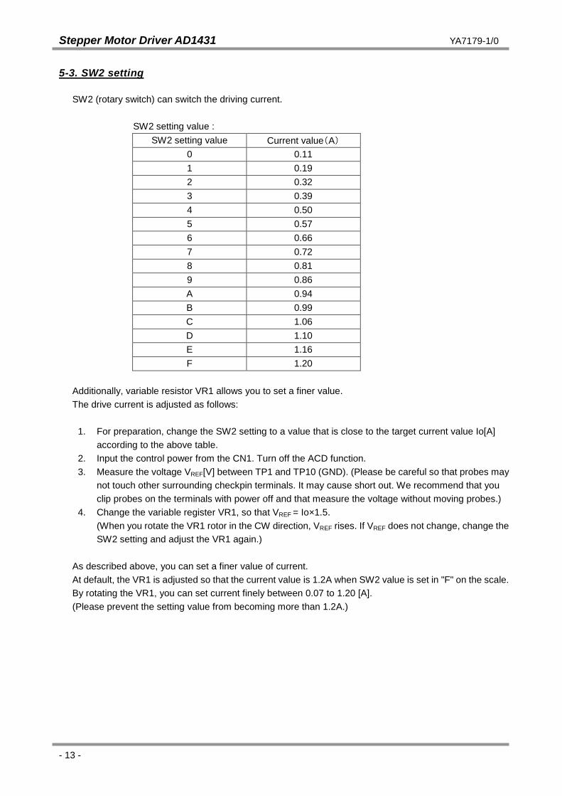
5-3. SW2 setting
SW2 (rotary switch) can switch the driving current.
SW2 setting value : SW2 setting value Current value(A)
0 0.11 1 0.19 2 0.32 3 0.39 4 0.50 5 0.57 6 0.66 7 0.72 8 0.81 9 0.86 A 0.94 B 0.99 C 1.06 D 1.10 E 1.16 F 1.20
Additionally, variable resistor VR1 allows you to set a finer value. The drive current is adjusted as follows:
1. For preparation, change the SW2 setting to a value that is close to the target current value Io[A]
according to the above table. 2. Input the control power from the CN1. Turn off the ACD function. 3. Measure the voltage VREF[V] between TP1 and TP10 (GND). (Please be careful so that probes may
not touch other surrounding checkpin terminals. It may cause short out. We recommend that you clip probes on the terminals with power off and that measure the voltage without moving probes.)
4. Change the variable register VR1, so that VREF = Io×1.5. (When you rotate the VR1 rotor in the CW direction, VREF rises. If VREF does not change, change the SW2 setting and adjust the VR1 again.)
As described above, you can set a finer value of current. At default, the VR1 is adjusted so that the current value is 1.2A when SW2 value is set in "F" on the scale. By rotating the VR1, you can set current finely between 0.07 to 1.20 [A]. (Please prevent the setting value from becoming more than 1.2A.)

Stepper Motor Driver AD1431 YA7179-1/0
- 14 -
5-4. SW3 setting
When auto current down setting is selected, SW3 can set the driving current in the current down setting. SW3 setting:
SW3-1 SW3-2 SW3-3 Driving current
Setting
ON - - 75%
- ON - 50%
- - ON 25%
When you change SW3, 100% of the driving current flows as shown below. Please note that the motor and driver may produce heat if other than the setting location is selected. Please make the rotor keep at the setting location without fail. (To set SW3-1 and 3-3, turn the rotor of SW3 to the limit. To set SW3-2, stop the rotor so as to make the rotor stop at the middle. (The rotor helps to stop at the middle.))
Motor driving current when you change the setting of SW3 with auto current down 5-5. LED display
The LEDs (D3 and D4)lights under the following conditions. D3 : It lights green using +5V power supply generated by the DC-DC from the control power. D4 : It lights red when the motor coil connected with the driver becomes short or open or when the
temperature of the driver IC raises and overheat protection circuit operates. In that cases, the motion of the driver stops. To make the driver run again, please power off once and power on again.
5-6. Default setting
SW1: bit1:OFF, bit2:OFF, bit3:OFF, bit4:OFF 1 pulse method / 4W1-2 phase excitation, 1/16 steps SW2: Setting 0 Driving current value 0.11A SW3: Setting 2 To lower the current value to 50% after input pulse stops in the case that the ACD
function is selected.
Driving current
SW3-1 setting SW3-2 setting SW3-3 setting Other than set value Other than set value
Driving current
SW3-1 setting SW3-2 setting SW3-3 setting Other than set value Other than set value

Stepper Motor Driver AD1431 YA7179-1/0
- 15 -
6. Handling precautions
6-1. This driver is a natural cooling type. Put this product in well-ventilated place as possible and space more than 10mm out around this driver.
6-2. Do not use in place with dust, oil mist, corrosive gas, etc. Additionally, remove dust periodically. 6-3. Do not put this driver in place with excessive vibration and shock directly 6-4. Make sure to keep the signal line (CN2), the power line (CN1) and the motor line (CN3) away from
one another to prevent noises. 6-5. If there are noise sources such as relays, high-pressure switching equipments or inverters, these
may cause induced and radiation noises mix in the signal lines or power lines and may cause malfunctions. Make sure to keep the wires and driver from such noise source as possible.
6-6. Be careful when you touch metal parts. It may result in injury on your finger by an angle of the metal. 6-7. Do not touch the board of this product while the power is supplied. When you move, wire, maintain
and inspect this product, power it off. 6-8. Be careful if you touch the product while the power is supplied and just after the power turns off. The
product may be hot. 6-9. Keep this driver out of reach of children. 6-10. Store this driver in place within the predetermined range of temperature and humidity. Do not leave it
in place subject to direct sunlight. 6-11. Plug in the connectors closely. Do not insert and remove connectors with wet hands. 6-12. If smoking, abnormal smell or noise occur, shut down the power immediately.
7. Accessories
Connector for CN1 IL-G-2S-S3C2-SA (Japan Aviation Electronics Industry, Ltd) 1 pc Connector for CN2 IL-G-10S-S3C2-SA (Japan Aviation Electronics Industry, Ltd) 1 pc Connector for CN3 IL-G-6S-S3C2-SA (Japan Aviation Electronics Industry, Ltd) 1 pc Contact for connectors IL-G-C2-SC-10000 (Japan Aviation Electronics Industry, Ltd) 16 pcs
Applicable wire : AWG22 to28 The above components are attached. Use the following crimp tools for clamping contact. CT150-1-ILG (Japan Aviation Electronics Industry, Ltd) Applicable wire : AWG26 to 28 CT150-1B-ILG (Japan Aviation Electronics Industry, Ltd) Applicable wire : AWG24 to 26 CT150-1C-ILG (Japan Aviation Electronics Industry, Ltd) Applicable wire : AWG22 to 24
or equivalent
Stepper Motor Driver AD1431 YA7179-1/0
- 16 -
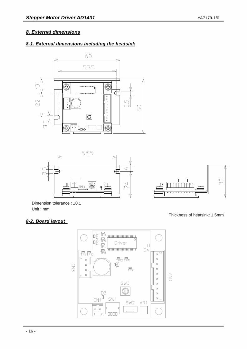
8. External dimensions
8-1. External dimensions including the heatsink
Dimension tolerance : ±0.1 Unit : mm
Thickness of heatsink: 1.5mm 8-2. Board layout

Stepper Motor Driver AD1431 YA7179-1/0
- 17 -
CAUTION The descriptions in this manual may be changed without prior notice to improve performance or quality.
Nippon Pulse Motor Co., Ltd. Head Office: No.16-13, 2-chome, Hongo, Bunkyo-ku, Tokyo, 113-0033, Japan TEL: 81-3-3813-8841 FAX: 81-3-3813-8665 Web: http://www.pulsemotor.com E-mail: [email protected]
Issued in February 2012