steppert motor interfacing with specific angle entered through keypad
TRANSCRIPT

PROJECT PAPER
Course no: EEE 4620
PROJECT: STEPPER MOTOR INTERFACING WITH SPECIFIC ANGLE
ENTERED THROUGH KEYPAD
Group No: 3
Student Id of the Group Member:
112419
112423
112426
112416
112414
112308
OBJECTIVE:
The objective of this project is to acquainted with the controlling of stepper motor via keypad. Whatever
we give input by keypad, stepper motor will rotate according to that given. We rotate the stepper motor
for some specific angle. Here in our project specific angle: 45o, 90o, 135o, 180o, 225o, 270o, 315o .
THEORY:
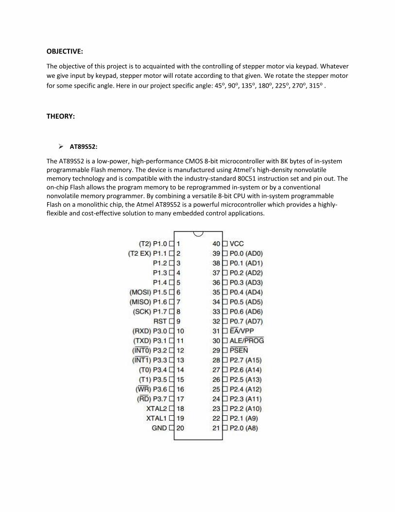
AT89S52:
The AT89S52 is a low-power, high-performance CMOS 8-bit microcontroller with 8K bytes of in-system programmable Flash memory. The device is manufactured using Atmel’s high-density nonvolatile memory technology and is compatible with the industry-standard 80C51 instruction set and pin out. The on-chip Flash allows the program memory to be reprogrammed in-system or by a conventional nonvolatile memory programmer. By combining a versatile 8-bit CPU with in-system programmable Flash on a monolithic chip, the Atmel AT89S52 is a powerful microcontroller which provides a highly-flexible and cost-effective solution to many embedded control applications.
Stepper motor:
Stepper motor is a brushless DC motor which position can be changed in discrete step. There are 3 kinds
of stepper motor. They are:
i) Unipolar ii) Bipolar iii) Universal
In this project we use unipolar stepper (2 phase). There are four coils in the motor.it has one winding
center tape per phase. These common wire often ganged together which makes it 5 or 6 wires motor.
The common wire should be connected to the supply. In other 4 wires we give instruction bit to rotate
the stepper motor. These instruction bit is taken from microprocessor, send it to motor driver whose
output is connected to the stepper motor. When we give high to the microcontroller pin it becomes low
through ULN2803A driver. This low bit grounded the coil of stepper motor. Then the north pole of rotor
directed to the coil which is grounded.
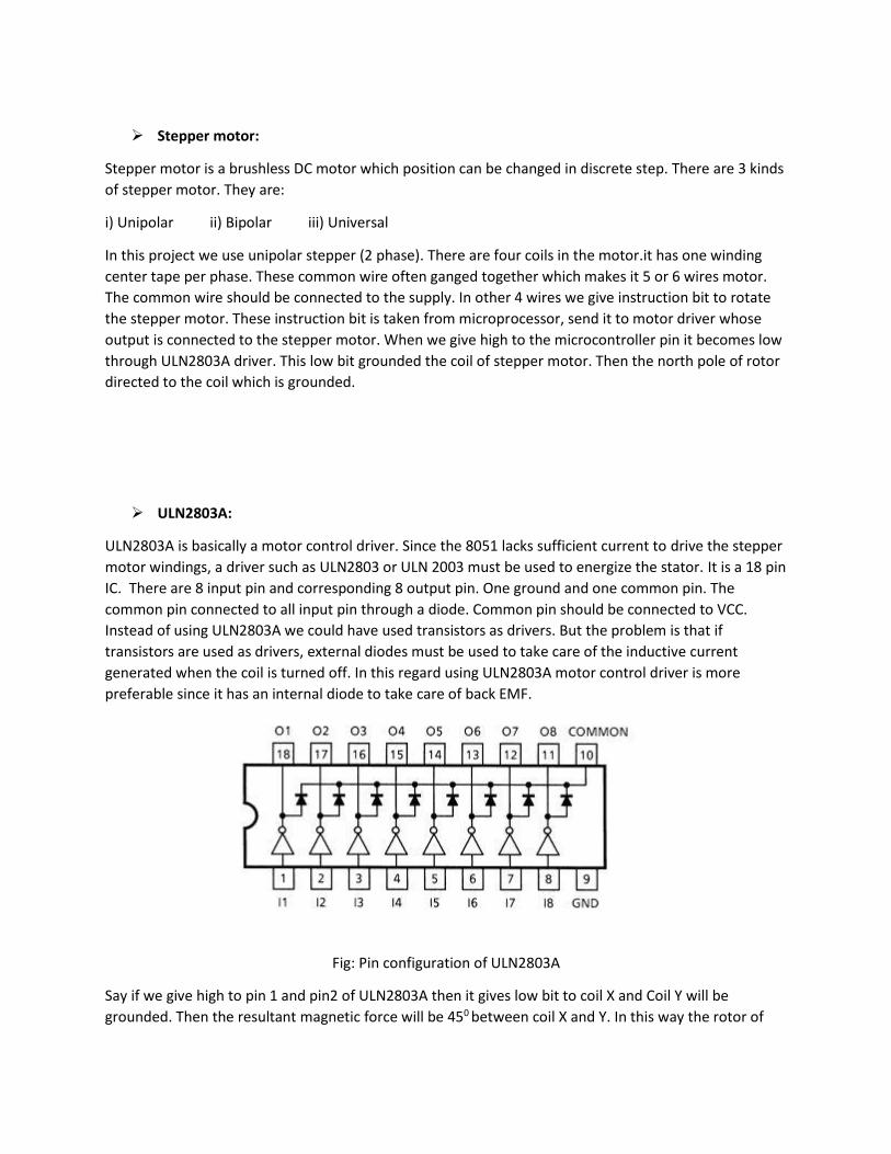
ULN2803A:
ULN2803A is basically a motor control driver. Since the 8051 lacks sufficient current to drive the stepper
motor windings, a driver such as ULN2803 or ULN 2003 must be used to energize the stator. It is a 18 pin
IC. There are 8 input pin and corresponding 8 output pin. One ground and one common pin. The
common pin connected to all input pin through a diode. Common pin should be connected to VCC.
Instead of using ULN2803A we could have used transistors as drivers. But the problem is that if
transistors are used as drivers, external diodes must be used to take care of the inductive current
generated when the coil is turned off. In this regard using ULN2803A motor control driver is more
preferable since it has an internal diode to take care of back EMF.
Fig: Pin configuration of ULN2803A
Say if we give high to pin 1 and pin2 of ULN2803A then it gives low bit to coil X and Coil Y will be
grounded. Then the resultant magnetic force will be 450 between coil X and Y. In this way the rotor of

the stepper motor can be rotate. Now to rotate the motor the stride angle of the motor should be
known.
Fig: Rotation of the rotor due to instruction bit supplied it via ULN2803A
Keyboard:
To give input to stepper motor we use keypad. Keyboards are organized in a matrix of rows and
columns. The CPU accesses both rows and columns through ports. When a key is pressed, a row
and a column make a contact. Otherwise, there is no connection between rows and columns.
The rows are connected to an output port and the columns are connected to an input port. The
microcontroller scans the keyboard continuously to detect and identify the key pressed. To
detect a pressed key, the microcontroller grounds all rows by providing 0 to the output latch
then it reads the columns.
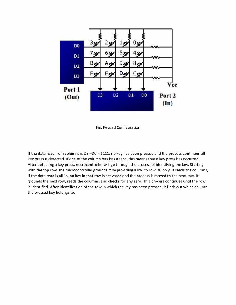
Fig: Keypad Configuration
If the data read from columns is D3 –D0 = 1111, no key has been pressed and the process continues till
key press is detected. If one of the column bits has a zero, this means that a key press has occurred.
After detecting a key press, microcontroller will go through the process of identifying the key. Starting
with the top row, the microcontroller grounds it by providing a low to row D0 only. It reads the columns,
if the data read is all 1s, no key in that row is activated and the process is moved to the next row. It
grounds the next row, reads the columns, and checks for any zero. This process continues until the row
is identified. After identification of the row in which the key has been pressed, it finds out which column
the pressed key belongs to.

Circuit Diagram:
Fig: Circuit Diagram
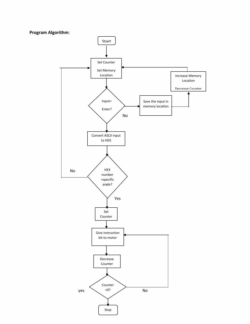
Program Algorithm:
No
Yes
No
Yes
yes No
Start
Set Counter
Set Memory
Location
Input=
Enter?
Save the input in
memory location
Increase Memory
Location
Decrease Counter
Convert ASCII input
to HEX
HEX
number
=specific
angle?
Set
Counter
Give instruction
bit to motor
Decrease
Counter
Counter
=0?
Stop

Assembly program:
ORG 00H MOV SP,#70H MOV PSW,#00H MOV R1,#60H ;save the ASCII value from keypad to memory location MOV R7,#4 ;number of input can be given from keypad to rotate in a specific angle ; program to take input from the keypad MOV P2,#0FFH K1: MOV P0,#0 MOV A,P2 ANL A,#00001111B CJNE A,#00001111B,K1 K2: ACALL DELAY MOV A,P2 ANL A,#00001111B CJNE A,#00001111B,OVER SJMP K2 OVER: ACALL DELAY MOV A,P2 ANL A,#00001111B CJNE A,#00001111B,OVER1 SJMP K2 OVER1:MOV P0,#11111110B MOV A,P2 ANL A,#00001111B CJNE A,#00001111B,ROW_0 MOV P0,#11111101B MOV A,P2 ANL A,#00001111B CJNE A,#00001111B,ROW_1 MOV P0,#11111011B MOV A,P2 ANL A,#00001111B CJNE A,#00001111B,ROW_2 MOV P0,#11110111B MOV A,P2 ANL A,#00001111B CJNE A,#00001111B,ROW_3 LJMP K2 ROW_0:MOV DPTR,#KCODE0 SJMP FIND ROW_1:MOV DPTR,#KCODE1 SJMP FIND ROW_2:MOV DPTR,#KCODE2 SJMP FIND ROW_3:MOV DPTR,#KCODE3 SJMP FIND

FIND: RRC A JNC MATCH INC DPTR SJMP FIND MATCH:CLR A MOVC A,@A+DPTR LJMP NXT1 NXT1: CJNE A,#01000100B,VALUIN ;if the given input is not ENTER (D button) then go to VALUIN label to store the input SJMP NXT ; if then jump to NXT label to convert the given input from ASCII to HEX VALUIN: MOV @R1,A ; store the given input to the memory location INC R1 ; increasing R1 to point next memory location DJNZ R7,NXT3 NXT3: LJMP K1 NXT: MOV R1,#60H ;to take input from keypad to rotate the motor until power supply is turn off MOV R7,#4 MOV A,61H ;take the 2nd input to A register ANL A,#00001111B ;make upper nibble zero SWAP A ;swap the value in A register MOV B,62H ;take the 3rd input to B register ANL B,#00001111B ;make upper nibble zero ORL A,B ; convert ASCII to HEX CMDEG: CJNE A,#01000101B,DIS ;check if the input is 45 DEG.if not then go to DIS label MOV R5,#72 ;number of loop to rotate motor 45 deg. HERE: ;give 8 step instructions to the motor through ULN2803A driver MOV A,#00001001B MOV P1,A ACALL DELAY MOV A,#00001000B MOV P1,A ACALL DELAY MOV A,#00001100B MOV P1,A ACALL DELAY MOV A,#00000100B MOV P1,A ACALL DELAY MOV A,#00000110B MOV P1,A ACALL DELAY MOV A,#00000010B MOV P1,A
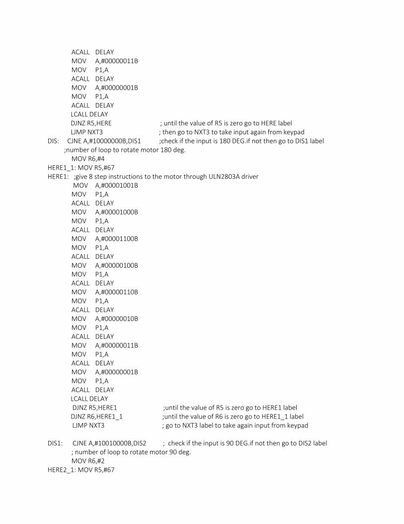
ACALL DELAY MOV A,#00000011B MOV P1,A ACALL DELAY MOV A,#00000001B MOV P1,A ACALL DELAY LCALL DELAY DJNZ R5,HERE ; until the value of R5 is zero go to HERE label LJMP NXT3 ; then go to NXT3 to take input again from keypad DIS: CJNE A,#10000000B,DIS1 ;check if the input is 180 DEG.if not then go to DIS1 label ;number of loop to rotate motor 180 deg. MOV R6,#4 HERE1_1: MOV R5,#67 HERE1: ;give 8 step instructions to the motor through ULN2803A driver MOV A,#00001001B MOV P1,A ACALL DELAY MOV A,#00001000B MOV P1,A ACALL DELAY MOV A,#00001100B MOV P1,A ACALL DELAY MOV A,#00000100B MOV P1,A ACALL DELAY MOV A,#00000110B MOV P1,A ACALL DELAY MOV A,#00000010B MOV P1,A ACALL DELAY MOV A,#00000011B MOV P1,A ACALL DELAY MOV A,#00000001B MOV P1,A ACALL DELAY LCALL DELAY DJNZ R5,HERE1 ;until the value of R5 is zero go to HERE1 label DJNZ R6,HERE1_1 ;until the value of R6 is zero go to HERE1_1 label LJMP NXT3 ; go to NXT3 label to take again input from keypad DIS1: CJNE A,#10010000B,DIS2 ; check if the input is 90 DEG.if not then go to DIS2 label ; number of loop to rotate motor 90 deg. MOV R6,#2 HERE2_1: MOV R5,#67

HERE2: ; give 8 step instructions to the motor through ULN2803A driver MOV A,#00001001B MOV P1,A ACALL DELAY MOV A,#00001000B MOV P1,A ACALL DELAY MOV A,#00001100B MOV P1,A ACALL DELAY MOV A,#00000100B MOV P1,A ACALL DELAY MOV A,#00000110B MOV P1,A ACALL DELAY MOV A,#00000010B MOV P1,A ACALL DELAY MOV A,#00000011B MOV P1,A ACALL DELAY MOV A,#00000001B MOV P1,A ACALL DELAY LCALL DELAY DJNZ R5,HERE2 ;until the value of R5 is zero go to HERE2 label DJNZ R6,HERE2_1 ;until the value of R6 is zero go to HERE2_1 label LJMP NXT3 ; go to NXT3 label to take again input from keypad DIS2: CJNE A,#00010101B,DIS3 ;check if the input is 315 DEG.if not then go to DIS3 label ;number of loop to rotate motor 315 deg. MOV R6,#7 HERE3_1: MOV R5,#67 HERE3: ; give 8 step instructions to the motor through ULN2803A driver MOV A,#00001001B MOV P1,A ACALL DELAY MOV A,#00001000B MOV P1,A ACALL DELAY MOV A,#00001100B MOV P1,A ACALL DELAY MOV A,#00000100B MOV P1,A ACALL DELAY MOV A,#00000110B
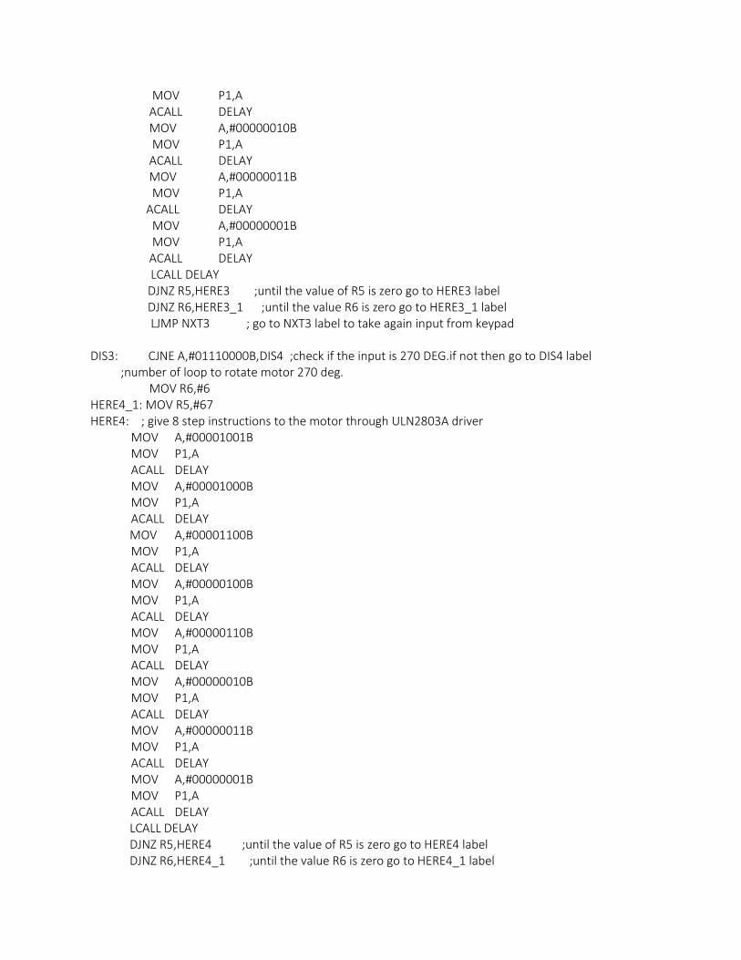
MOV P1,A ACALL DELAY MOV A,#00000010B MOV P1,A ACALL DELAY MOV A,#00000011B MOV P1,A ACALL DELAY MOV A,#00000001B MOV P1,A ACALL DELAY LCALL DELAY DJNZ R5,HERE3 ;until the value of R5 is zero go to HERE3 label DJNZ R6,HERE3_1 ;until the value R6 is zero go to HERE3_1 label LJMP NXT3 ; go to NXT3 label to take again input from keypad DIS3: CJNE A,#01110000B,DIS4 ;check if the input is 270 DEG.if not then go to DIS4 label ;number of loop to rotate motor 270 deg. MOV R6,#6 HERE4_1: MOV R5,#67 HERE4: ; give 8 step instructions to the motor through ULN2803A driver MOV A,#00001001B MOV P1,A ACALL DELAY MOV A,#00001000B MOV P1,A ACALL DELAY MOV A,#00001100B MOV P1,A ACALL DELAY MOV A,#00000100B MOV P1,A ACALL DELAY MOV A,#00000110B MOV P1,A ACALL DELAY MOV A,#00000010B MOV P1,A ACALL DELAY MOV A,#00000011B MOV P1,A ACALL DELAY MOV A,#00000001B MOV P1,A ACALL DELAY LCALL DELAY DJNZ R5,HERE4 ;until the value of R5 is zero go to HERE4 label DJNZ R6,HERE4_1 ;until the value R6 is zero go to HERE4_1 label
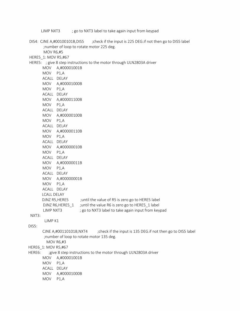
LJMP NXT3 ; go to NXT3 label to take again input from keypad DIS4: CJNE A,#00100101B,DIS5 ;check if the input is 225 DEG.if not then go to DIS5 label ;number of loop to rotate motor 225 deg. MOV R6,#5 HERE5_1: MOV R5,#67 HERE5: ; give 8 step instructions to the motor through ULN2803A driver MOV A,#00001001B MOV P1,A ACALL DELAY MOV A,#00001000B MOV P1,A ACALL DELAY MOV A,#00001100B MOV P1,A ACALL DELAY MOV A,#00000100B MOV P1,A ACALL DELAY MOV A,#00000110B MOV P1,A ACALL DELAY MOV A,#00000010B MOV P1,A ACALL DELAY MOV A,#00000011B MOV P1,A ACALL DELAY MOV A,#00000001B MOV P1,A ACALL DELAY LCALL DELAY DJNZ R5,HERE5 ;until the value of R5 is zero go to HERE5 label DJNZ R6,HERE5_1 ;until the value R6 is zero go to HERE5_1 label LJMP NXT3 ; go to NXT3 label to take again input from keypad NXT3: LJMP K1 DIS5: CJNE A,#00110101B,NXT4 ;check if the input is 135 DEG.if not then go to DIS5 label ;number of loop to rotate motor 135 deg. MOV R6,#3 HERE6_1: MOV R5,#67 HERE6: ;give 8 step instructions to the motor through ULN2803A driver MOV A,#00001001B MOV P1,A ACALL DELAY MOV A,#00001000B MOV P1,A
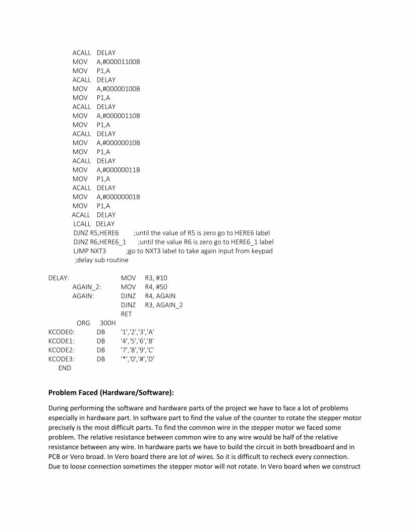
ACALL DELAY MOV A,#00001100B MOV P1,A ACALL DELAY MOV A,#00000100B MOV P1,A ACALL DELAY MOV A,#00000110B MOV P1,A ACALL DELAY MOV A,#00000010B MOV P1,A ACALL DELAY MOV A,#00000011B MOV P1,A ACALL DELAY MOV A,#00000001B MOV P1,A ACALL DELAY LCALL DELAY DJNZ R5,HERE6 ;until the value of R5 is zero go to HERE6 label DJNZ R6,HERE6_1 ;until the value R6 is zero go to HERE6_1 label LJMP NXT3 ;go to NXT3 label to take again input from keypad ;delay sub routine DELAY: MOV R3, #10 AGAIN_2: MOV R4, #50 AGAIN: DJNZ R4, AGAIN DJNZ R3, AGAIN_2 RET ORG 300H KCODE0: DB '1','2','3','A' KCODE1: DB '4','5','6','B' KCODE2: DB '7','8','9','C' KCODE3: DB '*','0','#','D' END
Problem Faced (Hardware/Software):
During performing the software and hardware parts of the project we have to face a lot of problems
especially in hardware part. In software part to find the value of the counter to rotate the stepper motor
precisely is the most difficult parts. To find the common wire in the stepper motor we faced some
problem. The relative resistance between common wire to any wire would be half of the relative
resistance between any wire. In hardware parts we have to build the circuit in both breadboard and in
PCB or Vero broad. In Vero board there are lot of wires. So it is difficult to recheck every connection.
Due to loose connection sometimes the stepper motor will not rotate. In Vero board when we construct
our circuit we check all the time whether it is shorted or not. If not then removing the solder we again
solder it. After that we have to check if the IC is getting any supply or not.
Remarks:
Before starting the project learn the operation of stepper motor, stride angle of the motor which is
going to be used, keypad and its connection. Before writing the assembly code make the algorithm of
the code. In the hardware part during soldering the IC base, don’t keep the IC in the IC base because it
may damage the IC. In keypad column and row should be connected properly otherwise it gives some
garbage value. By improving the project in further you can rotate solar panel with the rotation of sun, in
medical case it can be used as scanners, samplers, digital dental photography machine etc. In security
purpose it can be used in close circuit camera to rotate it. It can also be used in statues with a waving
hand.
