stepping motor ar series/ motorized actuator equipped with series · 2019-04-04 · x please read...
TRANSCRIPT
Thank you for purchasing an Oriental Motor product. This Manual describes product handling procedures and safety precautions.
• Please read it thoroughly to ensure safe operation.
•Always keep the manual where it is readily available.
HM-60340-3
Stepping Motor
AR Series/ Motorized actuator equipped with AR SeriesAC power input/DC power input Built-in Controller Type
USER MANUAL
z AC power input
KCC-REM-OMC-058 KCC-REM-OMC-059
z DC power input
KCC-REM-OMC-068
Introduction
AC power input type
DC power input type
AC power input type/ DC power input type Common
Operation type and setting
Method of control via Modbus RTU (RS-485 communication)
Method of control via industrial network
Appendix

2
1 Introduction
1 Before use ....................................................................................................................................................................10
2 Overview of the product ...........................................................................................................................................11
3 Safety precautions .....................................................................................................................................................133-1 Safety precautions ................................................................................................................................................................................ 133-2 Handling the battery ........................................................................................................................................................................... 153-3 Graphical symbols on the driver’s front panel ........................................................................................................................... 163-4 Warning sign ........................................................................................................................................................................................... 16
4 Precautions for use ....................................................................................................................................................17
2 AC power input type
1 System configuration ................................................................................................................................................22
2 Preparation ..................................................................................................................................................................232-1 Checking the product ......................................................................................................................................................................... 232-2 How to identify the product model ............................................................................................................................................... 242-3 Information about nameplate ......................................................................................................................................................... 262-4 Combinations of motors and drivers ............................................................................................................................................. 262-5 Input/output power ratings .............................................................................................................................................................. 272-6 Names and functions of parts .......................................................................................................................................................... 27
3 Installation ...................................................................................................................................................................303-1 Location for installation ...................................................................................................................................................................... 303-2 Installing the motor ............................................................................................................................................................................. 303-3 Installing a load ..................................................................................................................................................................................... 313-4 Permissible radial load and permissible axial load ................................................................................................................... 323-5 Installing the driver .............................................................................................................................................................................. 353-6 Installing the regeneration resistor ................................................................................................................................................ 363-7 Installing the battery ........................................................................................................................................................................... 36
4 Connection ..................................................................................................................................................................374-1 Connection example ........................................................................................................................................................................... 374-2 Grounding the motor and driver .................................................................................................................................................... 384-3 Connecting the main power supply .............................................................................................................................................. 394-4 Connecting the 24 VDC power supply, regeneration resistor and electromagnetic brake ....................................... 404-5 Connecting the I/O signals ................................................................................................................................................................ 424-6 Connecting the data setter ............................................................................................................................................................... 454-7 Connecting the RS-485 communication cable .......................................................................................................................... 454-8 Connecting and charging the battery .......................................................................................................................................... 464-9 Noise measures ..................................................................................................................................................................................... 464-10 Conformity to the EMC Directive .................................................................................................................................................... 47
5 Accessories ..................................................................................................................................................................495-1 Motor cable set ...................................................................................................................................................................................... 495-2 Setting tool ............................................................................................................................................................................................. 515-3 Wiring support tool .............................................................................................................................................................................. 515-4 Others ....................................................................................................................................................................................................... 52
3
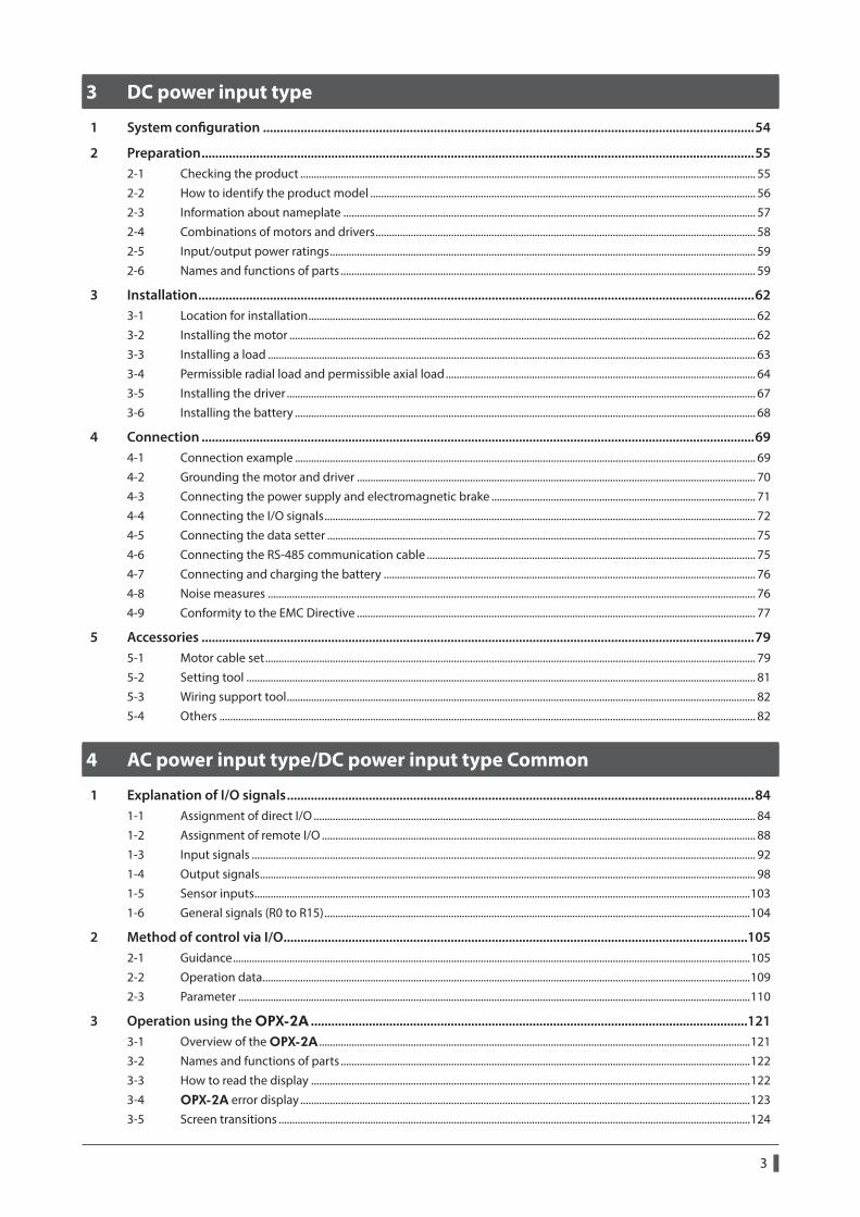
3 DC power input type
1 System configuration ................................................................................................................................................54
2 Preparation ..................................................................................................................................................................552-1 Checking the product ......................................................................................................................................................................... 552-2 How to identify the product model ............................................................................................................................................... 562-3 Information about nameplate ......................................................................................................................................................... 572-4 Combinations of motors and drivers ............................................................................................................................................. 582-5 Input/output power ratings .............................................................................................................................................................. 592-6 Names and functions of parts .......................................................................................................................................................... 59
3 Installation ...................................................................................................................................................................623-1 Location for installation ...................................................................................................................................................................... 623-2 Installing the motor ............................................................................................................................................................................. 623-3 Installing a load ..................................................................................................................................................................................... 633-4 Permissible radial load and permissible axial load ................................................................................................................... 643-5 Installing the driver .............................................................................................................................................................................. 673-6 Installing the battery ........................................................................................................................................................................... 68
4 Connection ..................................................................................................................................................................694-1 Connection example ........................................................................................................................................................................... 694-2 Grounding the motor and driver .................................................................................................................................................... 704-3 Connecting the power supply and electromagnetic brake .................................................................................................. 714-4 Connecting the I/O signals ................................................................................................................................................................ 724-5 Connecting the data setter ............................................................................................................................................................... 754-6 Connecting the RS-485 communication cable .......................................................................................................................... 754-7 Connecting and charging the battery .......................................................................................................................................... 764-8 Noise measures ..................................................................................................................................................................................... 764-9 Conformity to the EMC Directive .................................................................................................................................................... 77
5 Accessories ..................................................................................................................................................................795-1 Motor cable set ...................................................................................................................................................................................... 795-2 Setting tool ............................................................................................................................................................................................. 815-3 Wiring support tool .............................................................................................................................................................................. 825-4 Others ....................................................................................................................................................................................................... 82
4 AC power input type/DC power input type Common
1 Explanation of I/O signals .........................................................................................................................................841-1 Assignment of direct I/O .................................................................................................................................................................... 841-2 Assignment of remote I/O ................................................................................................................................................................. 881-3 Input signals ........................................................................................................................................................................................... 921-4 Output signals ........................................................................................................................................................................................ 981-5 Sensor inputs ........................................................................................................................................................................................1031-6 General signals (R0 to R15) ..............................................................................................................................................................104
2 Method of control via I/O ........................................................................................................................................1052-1 Guidance ................................................................................................................................................................................................1052-2 Operation data .....................................................................................................................................................................................1092-3 Parameter ..............................................................................................................................................................................................110
3 Operation using the OPX-2A ................................................................................................................................1213-1 Overview of the OPX-2A ................................................................................................................................................................1213-2 Names and functions of parts ........................................................................................................................................................1223-3 How to read the display ...................................................................................................................................................................1223-4 OPX-2A error display .......................................................................................................................................................................1233-5 Screen transitions ...............................................................................................................................................................................124

4
3-6 Monitor mode ......................................................................................................................................................................................1283-7 Data mode .............................................................................................................................................................................................1293-8 Parameter mode..................................................................................................................................................................................1323-9 Test mode ..............................................................................................................................................................................................1393-10 Copy mode ............................................................................................................................................................................................141
4 Inspection and maintenance .................................................................................................................................1424-1 Inspection ..............................................................................................................................................................................................1424-2 Warranty .................................................................................................................................................................................................1424-3 Disposal ..................................................................................................................................................................................................142
5 Alarms and warnings ...............................................................................................................................................1435-1 Alarms .....................................................................................................................................................................................................1435-2 Warning ..................................................................................................................................................................................................1505-3 Communication errors ......................................................................................................................................................................151
6 Troubleshooting and remedial actions ................................................................................................................152
5 Operation type and setting
1 Guidance ....................................................................................................................................................................154
2 Adjustment and setting ..........................................................................................................................................1582-1 Resolution ..............................................................................................................................................................................................1582-2 Operating current ...............................................................................................................................................................................1592-3 Standstill current .................................................................................................................................................................................1592-4 Acceleration/deceleration rate and acceleration/deceleration time ...............................................................................1602-5 Smooth drive ........................................................................................................................................................................................1602-6 Speed filter ............................................................................................................................................................................................1612-7 Moving average filter ........................................................................................................................................................................1622-8 Speed error gain ..................................................................................................................................................................................1622-9 Control mode .......................................................................................................................................................................................1632-10 Position loop gain, speed loop gain, speed loop integral time constant .......................................................................1632-11 Absolute-position backup system ................................................................................................................................................164
3 Operation type and function list ...........................................................................................................................165
4 Positioning operation ..............................................................................................................................................1664-1 Operation data .....................................................................................................................................................................................1664-2 Starting method of positioning operation ................................................................................................................................1684-3 Operation function.............................................................................................................................................................................1734-4 Push-motion operation ....................................................................................................................................................................177
5 Return-to-home operation .....................................................................................................................................1805-1 Operation sequence ..........................................................................................................................................................................1835-2 Position preset .....................................................................................................................................................................................187
6 Continuous operation .............................................................................................................................................1886-1 Starting method of continuous operation ................................................................................................................................1896-2 Variable speed operation .................................................................................................................................................................191
7 Other operation ........................................................................................................................................................1937-1 JOG operation ......................................................................................................................................................................................1937-2 Test operation ......................................................................................................................................................................................1947-3 Automatic return operation ............................................................................................................................................................1957-4 Stop operation .....................................................................................................................................................................................196
8 Coordination management ....................................................................................................................................1988-1 Position coordinate management ................................................................................................................................................1988-2 Wrap function ......................................................................................................................................................................................199

5
6 Method of control via Modbus RTU (RS-485 communication)
1 Guidance ....................................................................................................................................................................202
2 Communication specifications ..............................................................................................................................208
3 Setting the switches ................................................................................................................................................2113-1 Setting the AC power input ............................................................................................................................................................2113-2 Setting the DC power input ............................................................................................................................................................213
4 Setting of RS-485 communication ........................................................................................................................215
5 Communication mode and communication timing ..........................................................................................2165-1 Communication mode ......................................................................................................................................................................2165-2 Communication timing ....................................................................................................................................................................216
6 Message .....................................................................................................................................................................2176-1 Query .......................................................................................................................................................................................................2176-2 Response ................................................................................................................................................................................................219
7 Function code ...........................................................................................................................................................2217-1 Reading from a holding register(s) (03h) ...................................................................................................................................2217-2 Writing to a holding register (06h) ...............................................................................................................................................2227-3 Diagnosis (08h) ....................................................................................................................................................................................2237-4 Writing to multiple holding registers (10h) ...............................................................................................................................224
8 Register address list .................................................................................................................................................2268-1 Operation commands .......................................................................................................................................................................2268-2 Maintenance commands .................................................................................................................................................................2288-3 Monitor commands ...........................................................................................................................................................................2298-4 Parameter R/W commands .............................................................................................................................................................232
9 Group send ................................................................................................................................................................244
10 Setting example of the operation .........................................................................................................................24610-1 Positioning operation........................................................................................................................................................................24610-2 Continuous operation .......................................................................................................................................................................24910-3 Return-to-home operation ..............................................................................................................................................................251
11 Detection of communication errors .....................................................................................................................25311-1 Communication errors ......................................................................................................................................................................25311-2 Alarms and warnings .........................................................................................................................................................................253
12 Timing charts ............................................................................................................................................................254
7 Method of control via industrial network
1 Setting the switches ................................................................................................................................................2581-1 Setting the AC power input ............................................................................................................................................................2581-2 Setting the DC power input ............................................................................................................................................................260
2 Method of control via CC-Link communication..................................................................................................2622-1 Guidance ................................................................................................................................................................................................2622-2 Operation example of command selection method .............................................................................................................2672-3 Operation example of command fixation method ................................................................................................................275
3 Method of control via EtherCAT communication ...............................................................................................2813-1 Guidance ................................................................................................................................................................................................2813-2 Basic operating procedures ............................................................................................................................................................287
4 Details of remote I/O ...............................................................................................................................................2904-1 Input signals to the driver ................................................................................................................................................................2904-2 Output signals from the driver ......................................................................................................................................................291

6
5 Command code list ..................................................................................................................................................2935-1 Group function ....................................................................................................................................................................................2935-2 Maintenance command ...................................................................................................................................................................2945-3 Monitor command .............................................................................................................................................................................2955-4 Operation data .....................................................................................................................................................................................2975-5 User parameters ..................................................................................................................................................................................298
8 Appendix
1 Timing charts ............................................................................................................................................................308
2 Specifications ............................................................................................................................................................319
3 General specifications .............................................................................................................................................3203-1 AC power input ....................................................................................................................................................................................3203-2 DC power input ...................................................................................................................................................................................321
4 Regulations and standards .....................................................................................................................................3224-1 UL Standards ........................................................................................................................................................................................3224-2 EU Directives .........................................................................................................................................................................................3224-3 Republic of Korea, Radio Waves Act .............................................................................................................................................3234-4 RoHS Directive .....................................................................................................................................................................................323

7
Specification Change of DriverSome specifications have been changed in this product. There are differences in data setting range, etc. between the product after the change and before the change. For the driver before the specification change, contact your nearest Oriental Motor sales office.
This manual describes contents of the driver which is after the specification change. When using the driver which is before the specification change, take note of the following points.
1. Some setting items have been changed
Push current
Before the specification change
After the specification change
0 to 500 (1=0.1%) 0 to 1,000 (1=0.1%)
NET-IN input functionThe following input signals can be assigned in the product after the specification change.
• 24: ALM-RST • 25: P-PRESET • 26: P-CLR
Pay attention to the data update
z When the data is set using the support software MEXE02, use the MEXE02 which software version is 3.00 or laterIf the MEXE02 is older version than 3.00, the value after the specification change can not be set.
z When the following data passing is performed, the most recent value will not be updated
1) When the MEXE02 data which has set the value after the specification change is opened using the older MEXE02 than the Version 3.00
If the data is opened by the older MEXE02 than the Version 3.00, the data will be changed to the initial value.
Saves the data Opens the data
Latest value
Data le
Latest value Initial value
MEXE02 Ver.3.00 or later MEXE02 older than Ver.3.00
2) When an accessory data setter OPX-2A data which has set the value after the specification change is downloaded to the driver that is before the specification change
The value which is after the specification change will not be updated to the driver which is before the specification change, and the value presently set is kept.
Uploads the data Downloads the dataOPX-2A
Value before the change
Driver after specication change Driver before specication change
Latest valueLatest value

8
2. The upper limit of the alarm output has been changedThe maximum speed for push-motion operation has been changed. If push-motion operation is started after setting higher speed than 30 r/min in the driver which is before the specification change, an operation data error alarm will generate.
Maximum speed for push-motion operation
Before the specification change
After the specification change
30 r/min 500 r/min

1 Introduction
This part explains the product overview and safety precautions in addition to the types and descriptions about operating manuals.
Table of contents
1 Before use ............................................... 10
2 Overview of the product ...................... 11
3 Safety precautions ................................ 133-1 Safety precautions .......................................... 133-2 Handling the battery ..................................... 153-3 Graphical symbols on the driver’s front
panel .................................................................... 163-4 Warning sign .................................................... 16
4 Precautions for use ................................ 17

Before use
1 Introduction
10
1 Before use
Only qualified personnel of electrical and mechanical engineering should work with the product.Use the product correctly after thoroughly reading the section “3 Safety precautions” on p.13. In addition, be sure to observe the contents described in warning, caution, and note in this manual.The product described in this manual has been designed and manufactured to be incorporated in general industrial equipment. Do not use for any other purpose. Oriental Motor Co., Ltd. is not responsible for any damage caused through failure to observe this warning.
Related operating manualsFor operating manuals not included with the product, contact your nearest Oriental Motor sales office or download from Oriental Motor Website Download Page.
Operating manual nameIncluded or not included
with product
AR Series OPERATING MANUAL Motor Included
AR Series/Motorized actuator equipped with AR Series OPERATING MANUAL Driver
Included
AR Series/Motorized actuator equipped with AR Series USER MANUAL (this document)
Not included
APPENDIX UL Standards for AR Series Included
Read the following operating manuals in combination when using a motorized actuator.
Operating manual nameIncluded or not included
with product
OPERATING MANUAL Actuator Included
Motorized actuator Function Setting Edition Not included
About terms and unitsTerms and units to be used vary depending on a motor or motorized actuator. This manual explains by using the terms of the motor.When the motorized actuator is used, read this manual by replacing the terms.
Motor Motorized actuator
Term
Torque Thrust force
Moment of inertia Mass
Rotation Movement
CW direction FWD direction
CCW direction RVS direction
Rotation speed Speed
Resolution Minimum travel amount
UnitN·m N
kHz/s m/s2

Overview of the product1 Introduction
11
2 Overview of the product
The AR Series consists of a driver with built-in controller function and a motor with built-in rotor position detection sensor. This product can be controlled via I/O, Modbus (RTU), or industrial network communication using the network converter. Operation data and parameters can be set using any of the support software MEXE02, accessory data setter OPX-2A, or RS-485 communication.
Main features
z Introducing closed loop controlThe AR Series can continue its operation even upon encountering quick acceleration or an abrupt change in load. Monitoring the speed and amount of rotation while the motor is running, the AR Series performs the closed-loop control under overload and similar conditions to continue its operation at the maximum torque.
z Three operation typesPositioning operation, return-to-home operation, and continuous operation can be performed.Up to 64 operation data points can be set, and multi-point positioning is also possible.
z Compatible with Modbus RTU (RS-485 communication)Operation data and parameters can be set from the master controller, and start and stop commands of operation can be executed as well.Up to 31 drivers can be connected to one master.
z Absolute-position backup systemWhen connecting an accessory battery set, this product can be used in the absolute-position backup system. Positions will be retained in the event of a power outage or after turning off the driver power supply.
z Energy-savingMotor and driver losses have been substantially reduced to achieve low heat generation and save energy.Since the motor and driver generate much less heat, they can now be operated for longer hours at high speed, which was not possible with conventional motors/drivers.
z Supporting sink output and source outputThe driver supports both the current sink output circuit and the current source output circuit.
z Automatic control of the electromagnetic brakeThe driver automatically controls the electromagnetic brake, so the control signal input or the troublesome ladder logic design can be saved.
z Alarm and warning functionsThe driver provides alarms that are designed to protect the driver from overheating, poor connection, error in operation, etc. (protective functions), as well as warnings that are output before the corresponding alarms generate (warning functions).
AccessoriesOperation data and parameters can be set using any of the MEXE02, OPX-2A, or RS-485 communication. Provide the MEXE02 or OPX-2A as necessary.
• MEXE02 .....The MEXE02 can be downloaded from Oriental Motor Website Download Page.When the MEXE02 is used, a communication cable for the support software CC05IF-USB (accessory) is needed to connect a PC and driver. Be sure to purchase it.
• OPX-2A ......This product can be purchased separately.
Related productsThe AR Series FLEX built-in controller type can be used via various network when connecting to a network converter.
Network converter model Supported network
NETC01-CC CC-Link Ver.1.1
NETC02-CC CC-Link Ver.2
NETC01-M2 MECHATROLINK-II
NETC01-M3 MECHATROLINK-III
NETC01-ECT EtherCAT

Overview of the product
1 Introduction
12
Function list
Main functions
Return-to-home operation
[Setting by parameters]
z 2-sensor mode
z 3-sensor mode
z Push-mode
z Data setting mode (Position preset)
Motor operation
[Setting by operation data and parameters]
z Positioning operation
Single-motion operationLinked-motion operation
Linked-motion operation 2Push-motion
Operation function
Data number selecting operationDirect positioning operation
Sequential positioning operation
Starting method
+
z Continuous operation
Other operations
[Setting by parameters]
z JOG operation
z Automatic return operation
Support functions
[Setting by parameters]
z Protective function Alarm detection Warning detection
z I/O function Input function selection Output function selection Input logic level setting
z Coordination setting Resolution (Electronic gear) Wrap function Motor rotation direction
z Return-to-home function Home position offset External sensor signal detection
z Stop operation STOP input action Hardware overtravel Software overtravel
z Motor function setting Operating current Standstill current Speed filter Moving average filter
External interface
Data setter
z Monitor function
z Operation data setting
z Parameter setting
z Data storing
z Download/Upload
z Data initialization
z Test function Test operation Teaching I/O test
RS-485 communication
z Operation start
z Operation data setting
z Parameter setting
z Monitor function
z Maintenance function

Safety precautions1 Introduction
13
3 Safety precautions
3-1 Safety precautions
The precautions described below are intended to prevent danger or injury to the user and other personnel through safe, correct use of the product. Use the product only after carefully reading and fully understanding these instructions.
Handling the product without observing the instructions that accompany a "WARNING" symbol may result in serious injury or death.
Handling the product without observing the instructions that accompany a "CAUTION" symbol may result in injury or property damage.
The items under this heading contain important handling instructions that the user should observe to ensure the safe use of the product.
AC power input/DC power input common
General • Do not use the product in explosive or corrosive environments, in the presence of flammable gases, locations
subjected to splashing water, or near combustibles. Doing so may result in fire, electric shock, or injury. • Assign qualified personnel to the task of installing, wiring, operating/controlling, inspecting, and troubleshooting
the product. Failure to do so may result in fire, electric shock, injury, or damage to equipment. • Do not transport, install the product, perform connections, or inspections when the power is on. Always turn the
power off before carrying out these operations. Failure to do so may result in electric shock. • Take measures to keep the moving part in position if the product is used in vertical operations such as elevating
equipment. The motor loses holding torque when the power is shut off, allowing the moving parts to fall and possibly cause injury or damage to equipment.
• The brake mechanism of an electromagnetic brake motor is used for the purpose to hold the moving part and motor in position. Do not use it as a deceleration/safety brake. Doing so may result in injury or damage to the equipment.
• When the driver generates an alarm (any of the driver's protective functions is triggered), the motor will stop and lose its holding torque. Accordingly, provide measures to hold the moving part in place in the event of an alarm. Failure to do so may result in injury or damage to equipment.
• If the driver generates an alarm (any of the driver protective functions is triggered), remove the cause before clearing the alarm (protective function). Continuing the operation without removing the cause of the problem may cause malfunction of the motor and driver, leading to injury or damage to equipment.
Installation • Install the motor and driver inside an enclosure. Failure to do so may result in electric shock or injury.
Connection • Always keep the power supply voltage of the driver within the specified range. Failure to do so may result in fire or
electric shock. • Connect the cables securely according to the wiring diagram. Failure to do so may result in fire or electric shock. • Do not forcibly bend, pull, or pinch the connection cable. Doing so may result in fire or electric shock. • Turn off the power to both the PC and driver before connecting your PC to the driver. Failure to do so may result in
electric shock.
Operation • Turn off the driver power supply in the event of a power failure. Otherwise, the motor may suddenly start when the
power is restored, causing injury or damage to equipment. • Do not turn the FREE input to ON while the motor is operating. The motor will stop and lose its holding power.
Doing so may result in injury or damage to equipment.
Safety precautions
1 Introduction
14
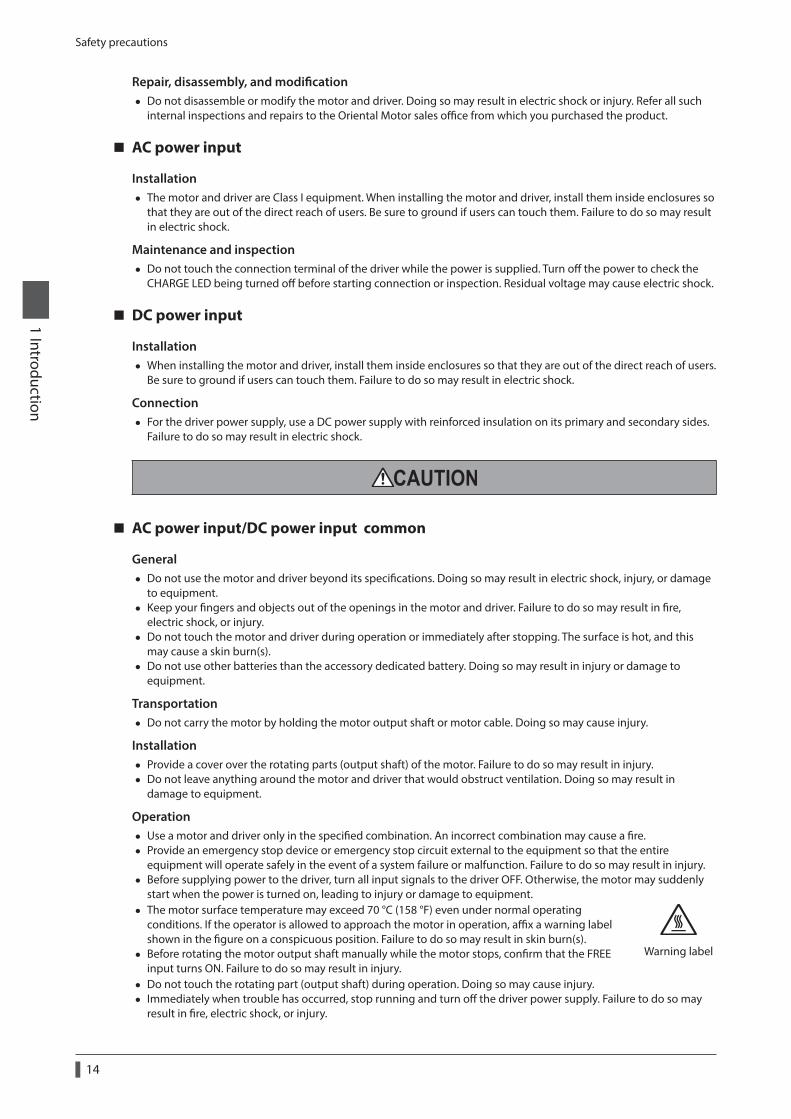
Repair, disassembly, and modification • Do not disassemble or modify the motor and driver. Doing so may result in electric shock or injury. Refer all such
internal inspections and repairs to the Oriental Motor sales office from which you purchased the product.
AC power input
Installation • The motor and driver are Class I equipment. When installing the motor and driver, install them inside enclosures so
that they are out of the direct reach of users. Be sure to ground if users can touch them. Failure to do so may result in electric shock.
Maintenance and inspection • Do not touch the connection terminal of the driver while the power is supplied. Turn off the power to check the
CHARGE LED being turned off before starting connection or inspection. Residual voltage may cause electric shock.
DC power input
Installation • When installing the motor and driver, install them inside enclosures so that they are out of the direct reach of users.
Be sure to ground if users can touch them. Failure to do so may result in electric shock.
Connection • For the driver power supply, use a DC power supply with reinforced insulation on its primary and secondary sides.
Failure to do so may result in electric shock.
AC power input/DC power input common
General • Do not use the motor and driver beyond its specifications. Doing so may result in electric shock, injury, or damage
to equipment. • Keep your fingers and objects out of the openings in the motor and driver. Failure to do so may result in fire,
electric shock, or injury. • Do not touch the motor and driver during operation or immediately after stopping. The surface is hot, and this
may cause a skin burn(s). • Do not use other batteries than the accessory dedicated battery. Doing so may result in injury or damage to
equipment.
Transportation • Do not carry the motor by holding the motor output shaft or motor cable. Doing so may cause injury.
Installation • Provide a cover over the rotating parts (output shaft) of the motor. Failure to do so may result in injury. • Do not leave anything around the motor and driver that would obstruct ventilation. Doing so may result in
damage to equipment.
Operation • Use a motor and driver only in the specified combination. An incorrect combination may cause a fire. • Provide an emergency stop device or emergency stop circuit external to the equipment so that the entire
equipment will operate safely in the event of a system failure or malfunction. Failure to do so may result in injury. • Before supplying power to the driver, turn all input signals to the driver OFF. Otherwise, the motor may suddenly
start when the power is turned on, leading to injury or damage to equipment. • The motor surface temperature may exceed 70 °C (158 °F) even under normal operating
conditions. If the operator is allowed to approach the motor in operation, affix a warning label shown in the figure on a conspicuous position. Failure to do so may result in skin burn(s).
• Before rotating the motor output shaft manually while the motor stops, confirm that the FREE input turns ON. Failure to do so may result in injury.
Warning label
• Do not touch the rotating part (output shaft) during operation. Doing so may cause injury. • Immediately when trouble has occurred, stop running and turn off the driver power supply. Failure to do so may
result in fire, electric shock, or injury.

Safety precautions1 Introduction
15
• Use only an insulated slotted screwdriver to adjust the driver’s switches. Failure to do so may result in electric shock.
Maintenance and inspection • Do not touch the terminals while conducting the insulation resistance measurement or dielectric strength test.
Doing so may cause electric shock.
AC power input
Connection • The data edit connector (CN4) and RS-485 communication connectors (CN6/CN7) are not insulated. When
grounding the positive terminal of the power supply, do not connect any equipment (PC, etc.) whose negative terminal is grounded. Doing so may cause the driver and these equipment to short, damaging both.
Operation • Use a 24 VDC power supply that has been given reinforced insulation between the primary side and secondary
side. Failure to do so may cause electric shock.
DC power input
Connection • The power supply connector (CN1), data edit connector (CN3), and RS-485 communication connectors (CN6/CN7)
are not insulated. When grounding the positive terminal of the power supply, do not connect any equipment (PC, etc.) whose negative terminal is grounded. Doing so may cause the driver and these equipment to short, damaging both.
• When connecting, check the silk screen of the driver and pay attention to the polarity of the power supply. Reverse-polarity connection may cause damage to the driver. The power-supply circuit and the RS-485 communication circuit are not insulated. Therefore, when controlling multiple drivers via RS-485 communication, the reverse polarity of the power supply will cause a short circuit and may result in damage to the drivers.
Operation • For the power supply to the electromagnetic brake, use a DC power supply with reinforced insulation on its
primary and secondary sides. Failure to do so may result in electric shock.
3-2 Handling the battery
Be sure to observe the following instructions when using the accessory battery. Handling the battery without observing the instructions may cause the liquid leakage, heat generation and explosion, etc., which may result in injury or damage to equipment.
• Do not heat the battery or throw it into a fire. • Never short-circuit the battery or connect the positive and negative terminals in reverse. • When carrying/storing the battery, do not place it together with metal necklaces, hairpins, coins, keys or other
conductive objects. When storing the battery, store it away from direct sunlight in a place not subject to high temperature or high humidity.
• Do not disassemble or modify the battery. • Do not apply solder directly to the battery. • Use a dedicated driver to charge the battery. • The battery has a vent structure for the release of internal gas. Do not apply a strong force to the battery, since it
may cause this structure to deform. • When installing the battery into the machine, never place it inside a sealed structure. The battery sometimes
generates gas, which, if trapped, may cause a burst or an explosion due to ignition. • The battery contains an alkali solution. If the alkali solution comes in contact with the skin or clothes, flush the area
thoroughly with clean water. If the alkali solution gets into the eyes, do not rub. Flush the eyes thoroughly with clean water and seek immediate medical attention.
• Do not use the battery if there is leakage, discoloration, deformation or another abnormality. • Do not immerse the battery in water or seawater, nor allow it to become wet. Doing so may cause the battery to
generate heat or rust. • Do not scratch the battery and battery cable. A scratched battery easily causes shorting, resulting in leakage, heat
generation or bursting. • The battery is connected to the primary circuit, so do not touch the battery while the power is on.

Safety precautions
1 Introduction
16
• Do not forcibly bend, pull, or pinch the cable. Also, do not bend and flex the cable repeatedly. • Do not make a continuous vibration or excessive impact.
• Always charge the battery connecting to the driver before use. For charging method, refer to p.46 (AC power input), p.76 (DC power input).
• Nickel-metal-hydride cell is used in this battery. Disposal of the used batteries is subject to each country's regulations on environmental control. Contact your nearest Oriental Motor sales office if you have any questions.
3-3 Graphical symbols on the driver’s front panel
This is the Protective Earth Terminal. Be sure to ground because improper grounding may result in electric shock.
A high voltage is applied to the motor connector (CN2) and the main power supply input terminal (CN3). Do not touch these terminals while the power is on. Doing so may result in fire or electric shock. (AC power input)
3-4 Warning sign
A warning about handling precautions is described on the driver and battery.Be sure to observe the description contents when handling the driver or battery.
z Driver (AC power input)
Electrical hazard warning label
Material: PET
z Battery
Electrical hazard warning label
Material: Polypropylene

Precautions for use1 Introduction
17
4 Precautions for use
This chapter covers restrictions and requirements the user should consider when using the product.
AC power input/DC power input common
z Always use the accessory cable to connect the motor and driver.
Precautions for when the connection cable is used are described on p.19. Be sure to read before use.
z When conducting the insulation resistance measurement or the dielectric strength test, be sure to separate the connection between the motor and the driver.Conducting the insulation resistance measurement or dielectric strength test with the motor and driver connected may result in damage to the product.
z Do not apply a radial load and axial load in excess of the specified permissible limit.Operating the motor under an excessive radial load or axial load may damage the motor bearings (ball bearings). Be sure to operate the motor within the specified permissible limit of radial load and axial load. For details, refer to p.32 (AC power input), p.64 (DC power input).
z Use the motor in conditions where its surface temperature will not exceed 100 °C (212 °F).The driver has an overheat protection function, but the motor has no such feature. The motor surface temperature may exceed 100 °C (212 °F) under certain conditions (ambient temperature, operating speed, duty cycle, etc.). To prevent the motor bearings (ball bearings) from reaching its usable life quickly, use the motor in conditions where the surface temperature does not exceed 100 °C (212 °F).Use the geared motor in a condition where the gear case temperature does not exceed 70 °C (158 °F), in order to prevent deterioration of grease and parts in the gear case.If the motor is to be operated continuously, install the motor in a location where heat dissipation capacity equivalent to a level achieved with a heat sink [made of aluminum, 250×250×6 mm (9.84×9.84×0.24 in.)] is ensured.
z Holding torque at standstillThe motor holding torque is reduced by the current cutback function of the driver at motor standstill. When selecting a motor, check the holding torque at motor standstill in the specifications on the catalog.
z Do not use the electromagnetic brake for braking or as a safety brake.Do not use the electromagnetic brake as a means to decelerate and stop the motor. The brake hub of the electromagnetic brake will wear significantly and the braking force will drop. Since the power off activated type electromagnetic brake is equipped, it helps maintain the position of the load when the power is cut off, but this brake cannot securely hold the load in place. Accordingly, do not use the electromagnetic brake as a safety brake. To use the electromagnetic brake to hold the load in place, do so after the motor has stopped.
z Double shaft type motorDo not apply a load torque, radial load, or axial load to the output shaft on the opposite side of the motor output shaft.
z Preventing electrical noiseFor measures with regard to noise, refer to p.46 (AC power input), p.76 (DC power input).

Precautions for use
1 Introduction
18
z Rotating direction of output shaftThe motor output shaft rotates in the figure at the factory setting. The rotation direction can be changed by the parameter.
•When setting the position (travel amount) to a positive value
CW direction
•When setting the position (travel amount) to a negative value
CCW direction
The relationship between the rotating direction of the motor shaft and that of the gear output shaft changes as follows, depending on the gear type and gear ratio. Check with the table.
Type of gear Gear ratioRotating direction
(relative to the motor rotating direction)
TH geared3.6, 7.2, 10 Same direction
20, 30 Opposite direction
FC geared, PS geared, PN geared All gear ratios Same direction
Harmonic geared All gear ratios Opposite direction
z Peak torque of geared motorAlways operate the geared motor under a load not exceeding the peak torque. If the load exceeds the peak torque, the gear part will be damaged.
z Do not perform push-motion operation with geared motors.Doing so may result in damage to the motor or gear part.
z About grease of geared motorOn rare occasions, a small amount of grease may ooze out from the geared motor. If there is concern over possible environmental damage resulting from the leakage of grease, check for grease stains during regular inspections. Alternatively, install an oil pan or other device to prevent leakage from causing further damage. Oil leakage may lead to problems in the customer's equipment or products.
z Saving data to the non-volatile memoryDo not turn off the main power supply or DC power supply while writing the data to the non-volatile memory, and also do not turn off for 5 seconds after the completion of writing the data. Doing so may abort writing the data and cause an EEPROM error alarm to generate. The non-volatile memory can be rewritten approximately 100,000 times.
z Motor excitation at power ONThe motor is excited when the DC power supply and main power supply are on. If the motor is required to be in a non-excitation state when turning on the power, assign the C-ON input to direct I/O or remote I/O.
z Operation of multi-rotation for absolute-position backup system * • Even if the present position is preset, the operation range of multi-rotation (−167,772 to +167,772 revolutions) is
not changed because the driver stores the position from the home position. • If the power is turned on again while the operation range of multi-rotation (−167,772 to +167,772 revolutions) is
being exceeded, an alarm of the absolute position error generates. Reset the alarm of the absolute position error with either of the following methods. − Turn the P-CLR input from ON to OFF. (effective at the OFF edge of the P-CLR input). − Reset the absolute position error alarm using the MEXE02, OPX-2A or via RS-485 communication.
* Operation of multi-rotation refers to repeating continuous operation to the same direction or positioning operation.

Precautions for use1 Introduction
19
AC power input
z Preventing leakage currentStray capacitance exists between the driver's current-carrying line and other current-carrying lines, the earth and the motor, respectively. A high-frequency current may leak out through such capacitance, having a detrimental effect on the surrounding equipment. The actual leakage current depends on the driver's switching frequency, the length of wiring between the driver and motor, and so on. When providing a leakage current breaker, use the following products, for example, which have high-frequency signal protection:Mitsubishi Electric Corporation: NV series
z When an alarm of overvoltage protection is generatedIf vertical drive (gravitational operation) such as elevator applications is performed or if sudden start-stop operation of a large inertial load is repeated frequently, an alarm of overvoltage protection may be detected. If the overvoltage protection alarm is detected, adjust the driving condition or use an accessory regeneration resistor.
z Note on connecting a power supply whose positive terminal is groundedThe data edit connector (CN4) and RS-485 communication connectors (CN6/CN7) are not insulated. When grounding the positive terminal of the power supply, do not connect any equipment (PC, etc.) whose negative terminal is grounded. Doing so may cause the driver and these equipment to short, damaging both. Use the OPX-2A to set data, etc.
DC power input
z When an alarm of overvoltage protection is generatedIf vertical drive (gravitational operation) such as elevator applications is performed or if sudden start-stop operation of a large inertial load is repeated frequently, an alarm of overvoltage protection may be detected. If the overvoltage protection alarm is detected, adjust the driving condition.
z Note on connecting a power supply whose positive terminal is groundedThe power supply connector (CN1), data edit connector (CN3), and RS-485 communication connectors (CN6/CN7) are not insulated. When grounding the positive terminal of the power supply, do not connect any equipment (PC, etc.) whose negative terminal is grounded. Doing so may cause the driver and these equipment to short, damaging both. Use the OPX-2A to set data, etc.
Notes when the connection cable is usedNote the following points when an accessory cable is used.
z When inserting the connectorHold the connector main body, and insert it in straight securely.Inserting the connector in an inclined state may result in damage to terminals or a connection failure.
z When unplugging the connectorPull out the connector in straight while releasing the lock part of the connector. Pulling out the connector with holding the cable (lead wire) may result in damage to the connector.
z Bending radius of cableUse the cable in a state where the bending radius of the cable is more than six times of the cable diameter.In the case of the lead wire type, use in a state where the bending radius is more than four times of the diameter of the lead wires.
More than 6 times of cable diameter
Precautions for use
1 Introduction
20
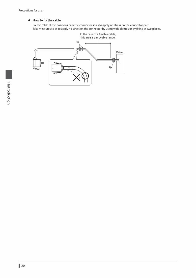
z How to fix the cableFix the cable at the positions near the connector so as to apply no stress on the connector part.Take measures so as to apply no stress on the connector by using wide clamps or by fixing at two places.
In the case of a exible cable,this area is a movable range.
Fix
Motor
Driver
Fix

2 AC power input type
This part explains contents specific to the AR Series AC power input type.
Table of contents
1 System configuration ............................ 22
2 Preparation ............................................. 232-1 Checking the product ................................... 232-2 How to identify the product model ......... 242-3 Information about nameplate ................... 262-4 Combinations of motors and drivers ....... 262-5 Input/output power ratings ........................ 272-6 Names and functions of parts .................... 27
3 Installation .............................................. 303-1 Location for installation ................................ 303-2 Installing the motor ....................................... 303-3 Installing a load ............................................... 313-4 Permissible radial load and
permissible axial load .................................... 323-5 Installing the driver ........................................ 353-6 Installing the regeneration resistor .......... 363-7 Installing the battery ..................................... 36
4 Connection ............................................. 374-1 Connection example ..................................... 374-2 Grounding the motor and driver .............. 384-3 Connecting the main power supply ........ 394-4 Connecting the 24 VDC power supply,
regeneration resistor and electromagnetic brake.................................. 40
4-5 Connecting the I/O signals .......................... 424-6 Connecting the data setter ......................... 454-7 Connecting the RS-485 communication
cable .................................................................... 454-8 Connecting and charging the battery .... 464-9 Noise measures ............................................... 464-10 Installing and wiring in compliance with
EMC Directive ................................................... 47
5 Accessories.............................................. 495-1 Motor cable set ................................................ 495-2 Setting tool ....................................................... 515-3 Wiring support tool ........................................ 515-4 Others ................................................................. 52

System configuration
2 AC power input type
22
1 System configuration
Thermostat output (AWG22)
Regeneration resistor (AWG18)
Connect to CN1
Connect to CN2
Single-phase 100-120 VSingle-phase 200-240 V
Noise lterUse a noise lter to eliminate noise.It has the e ect of reducing noise generated from the power supply and driver.
Power supplyUse the power supply within the rated voltage range.
24 VDC power supplyBe sure to connect it.
Circuit breaker or ground fault interrupt circuitBe sure to connect a circuit breaker or ground fault interrupt circuit to protect the wiring on the primary side.
Cable for motor *1This cable is used to connect the motor and driver.
Regeneration resistor *1Connect this resistor if vertical drive (gravitational operation) such as elevator applications is performed or if sudden start-stop operation of a large inertial load is repeated frequently.
Connect to CN4
Sensor signals: Connect to CN5
Master controller
Driver
Motor
Output signals: Connect to CN9
Input signals: Connect to CN8
Master controllerConnect when controlling the system via RS-485 communication.
OPX-2A *1
Or
PC in which the MEXE02has been installed. *2
Connect to CN10
Battery *1Connect this battery if you want to operate the driver in the absolutebackup system.
Grounding Grounding
GND24 VDC
*1 Accessory.*2 The PC must be supplied by the user. Use the accessory communication cable for the support software when
connecting the PC and driver.
Preparation2 AC pow
er input type
23
2 Preparation
This chapter explains the items you should check, as well as the name and function of each part.
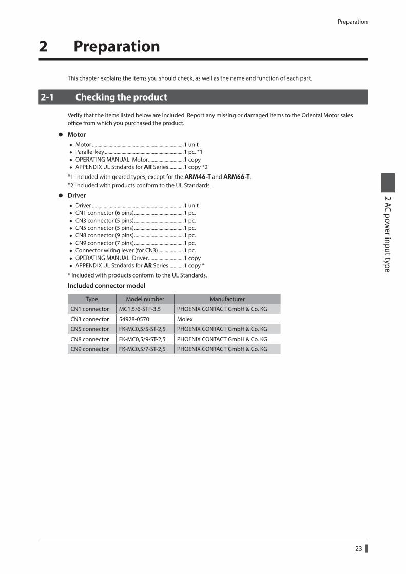
2-1 Checking the product
Verify that the items listed below are included. Report any missing or damaged items to the Oriental Motor sales office from which you purchased the product.
z Motor • Motor ........................................................................1 unit • Parallel key ..............................................................1 pc. *1 • OPERATING MANUAL Motor ............................1 copy • APPENDIX UL Stndards for AR Series ............1 copy *2
*1 Included with geared types; except for the ARM46-T and ARM66-T.*2 Included with products conform to the UL Standards.
z Driver • Driver ........................................................................1 unit • CN1 connector (6 pins) .......................................1 pc. • CN3 connector (5 pins) .......................................1 pc. • CN5 connector (5 pins) .......................................1 pc. • CN8 connector (9 pins) .......................................1 pc. • CN9 connector (7 pins) .......................................1 pc. • Connector wiring lever (for CN3) ....................1 pc. • OPERATING MANUAL Driver ............................1 copy • APPENDIX UL Stndards for AR Series ............1 copy *
* Included with products conform to the UL Standards.
Included connector model
Type Model number Manufacturer
CN1 connector MC1,5/6-STF-3,5 PHOENIX CONTACT GmbH & Co. KG
CN3 connector 54928-0570 Molex
CN5 connector FK-MC0,5/5-ST-2,5 PHOENIX CONTACT GmbH & Co. KG
CN8 connector FK-MC0,5/9-ST-2,5 PHOENIX CONTACT GmbH & Co. KG
CN9 connector FK-MC0,5/7-ST-2,5 PHOENIX CONTACT GmbH & Co. KG

Preparation
2 AC power input type
24
2-2 How to identify the product model
Check the model number of the motor and driver against the number shown on the nameplate. Refer to p.26 for how to identify the nameplate.
Motor
z Standard type
ARM 6 6 A 0 C1 2 3 4 5 6
z Geared type (except for FC geared type)
ARM 6 6 A C - T 7.2 U1 2 3 4 6 7 8 9
1 Series name ARM: AR Series motor
2 Motor frame size4: 42 mm (1.65 in.) 6: 60 mm (2.36 in.) 9: 85 mm (3.35 in.) [90 mm (3.54 in.) for geared type]
3 Motor length
4 Motor typeA: Single shaft B: Double shaft M: With electromagnetic brake
5 Additional function 0: Round shaft without shaft flat Blank: Round shaft with shaft flat on one side
6 Motor power supply input C: AC power input type
7 Type of gear
T: TH geared PS: PS geared N: PN geared H: Harmonic geared Blank: Standard
8 Gear ratioIndicates a number representing the gear ratio. Refer to the table next for the gear type and gear ratio.
9Cable outlet direction * (TH geared type only)
U: Upward direction L: Leftward direction R: Rightward direction Blank: Downward direction
* The cable outlet direction represents the one as viewed from the output shaft side in a state of placing it upward.
U: Upward direction
R: Rightward directionL: Leftward direction
Blank: Downward direction
Type of gear ratio
Type of gear Gear ratio
* The model name is “7” for the gear ratio 7.2 of the PS geared type.
TH geared 3.6, 7.2, 10, 20, 30
PS geared 5, 7.2 (*), 10, 25, 36, 50
PN geared ARM46: 5, 7.2, 10 ARM66, ARM98: 5, 7.2, 10, 25, 36, 50
Harmonic geared 50, 100

Preparation2 AC pow
er input type
25
z FC geared type
ARM 6 6 A C - FC 7.2 L A1 2 3 4 5 6 7 8 9
1 Series name ARM: AR Series motor
2 Motor frame size 4: 42 mm (1.65 in.) 6: 60 mm (2.36 in.)
3 Motor length
4 Motor type A: Single shaft
5 Motor power supply input C: AC power input type
6 Type of gear FC: FC geared
7 Gear ratio 7.2, 10, 20, 30
8 Output shaft direction * L: L shaft (Leftward direction) R: R shaft (Rightward direction)
9 Output shaft type A: Solid shaft
* The direction of the gearhead output shaft represents that as the view from the motor cable outlet side.
L: L shaft (Leftward direction) R: R shaft (Rightward direction)
Driver
ARD - C D1 2 3
1 Series name ARD: AR Series driver
2 Power supply input A: Single-phase 100-120 V C: Single-phase 200-240 V
3 Type D: Built-in controller type

Preparation
2 AC power input type
26
2-3 Information about nameplate
The figure shows an example.
Motor model
Specication
Serial number Manufacturing date
Driver modelInput specication
Output specication
Serial number Manufacturing date
The position describing the information may vary depending on the product.
2-4 Combinations of motors and drivers
Standard type
Single shaft Double shaft With electromagnetic brake
Motor model Driver model Motor model Driver model Motor model Driver model
ARM46AC
ARD-AD ARD-CD
ARM46BC
ARD-AD ARD-CD
ARM46MC
ARD-AD ARD-CD
ARM46A0C ARM46B0C ARM46M0C
ARM66AC ARM66BC ARM66MC
ARM66A0C ARM66B0C ARM66M0C
ARM69AC ARM69BC ARM69MC
ARM69A0C ARM69B0C ARM69M0C
ARM98AC ARM98BC ARM98MC
ARM98A0C ARM98B0C ARM98M0C
ARM911AC ARM911BC
ARM911A0C ARM911B0C
Geared type • The box (z) in the model name indicates a number representing the gear ratio. • The box () in the model name indicates U (upward direction), L (left direction), or R (right direction) representing
the cable outlet direction. The box () is blank when the cable outlet direction is downward.
Type of gearSingle shaft With electromagnetic brake
Motor model Driver model Motor model Driver model
TH geared
ARM46AC-TzARD-AD ARD-CD
ARM46MC-TzARD-AD ARD-CD
ARM66AC-Tz ARM66MC-Tz
ARM98AC-Tz ARM98MC-Tz
FC geared
ARM46AC-FCzLA
ARD-AD ARD-CD
− −ARM46AC-FCzRA
ARM66AC-FCzLA
ARM66AC-FCzRA
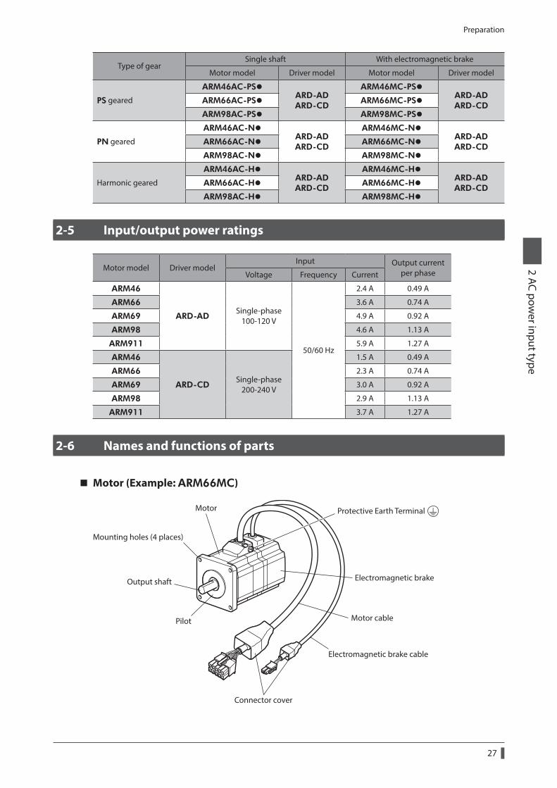
Preparation2 AC pow
er input type
27
Type of gearSingle shaft With electromagnetic brake
Motor model Driver model Motor model Driver model
PS geared
ARM46AC-PSzARD-AD ARD-CD
ARM46MC-PSzARD-AD ARD-CD
ARM66AC-PSz ARM66MC-PSz
ARM98AC-PSz ARM98MC-PSz
PN geared
ARM46AC-NzARD-AD ARD-CD
ARM46MC-NzARD-AD ARD-CD
ARM66AC-Nz ARM66MC-Nz
ARM98AC-Nz ARM98MC-Nz
Harmonic geared
ARM46AC-HzARD-AD ARD-CD
ARM46MC-HzARD-AD ARD-CD
ARM66AC-Hz ARM66MC-Hz
ARM98AC-Hz ARM98MC-Hz
2-5 Input/output power ratings
Motor model Driver modelInput Output current
per phaseVoltage Frequency Current
ARM46
ARD-ADSingle-phase
100-120 V
50/60 Hz
2.4 A 0.49 A
ARM66 3.6 A 0.74 A
ARM69 4.9 A 0.92 A
ARM98 4.6 A 1.13 A
ARM911 5.9 A 1.27 A
ARM46
ARD-CDSingle-phase
200-240 V
1.5 A 0.49 A
ARM66 2.3 A 0.74 A
ARM69 3.0 A 0.92 A
ARM98 2.9 A 1.13 A
ARM911 3.7 A 1.27 A
2-6 Names and functions of parts
Motor (Example: ARM66MC)
Output shaft
Pilot Motor cable
Motor
Connector cover
Electromagnetic brake cable
Electromagnetic brake
Protective Earth Terminal
Mounting holes (4 places)

Preparation
2 AC power input type
28
Driver (Example: ARD-CD)
PWR/ALM LEDC-DAT/C-ERR LED
Termination resistor setting switch(TERM.)
RS-485 communication connectors(CN6/CN7)
Address number setting switch (ID)
Data edit connector (CN4)
Motor connector (CN2)
Mounting hole (at the back)
Mounting hole (at the back)
CHARGE LED
Sensor signals connector (CN5)
Input signals connector (CN8)
Output signals connector (CN9)
Protective Earth Terminals
Electromagnetic brake terminals (CN1)
Regeneration resistor thermal input terminals (CN1)
24 VDC power supply input terminals (CN1)
Regeneration resistor terminals (CN3)
Main power input terminals (CN3)
Transmission rate setting switch (SW2)
Function setting switch (SW4)
Battery connector (CN10)

Preparation2 AC pow
er input type
29
Name Description Page
PWR/ALM LED
• PWR (Green) : This LED is lit while the 24 VDC power is input.
•ALM (Red) : This LED will blink if an alarm generates (a protective function is triggered). It is possible to check the generated alarm by counting the number of times the LED blinks.
p.143
C-DAT/C-ERR LED
•C-DAT (Green) : This LED blinks or is lit when the driver is communicating with the master controller properly via RS-485 communication.
•C-ERR (Red) : This LED will be lit if a RS-485 communication error occurs with the master controller.
−
Address number setting switch (ID)This switch is used when controlling the system via RS-485 communication. Sets the address number (slave address) of RS-485 communication using this switch and SW4-No.1 of the function setting switch. (Factory setting: 0) p.212
p.258 p.259Termination resistor setting switch
(TERM.)
This switch is used when controlling the system via RS-485 communication. Sets the termination resistor (120 Ω) of RS-485 communication. (Factory setting: OFF)
RS-485 communication connectors (CN6/CN7)
Connects the RS-485 communication cable. p.45
Output signals connector (CN9) Connects the output signals.
p.42Input signals connector (CN8) Connects the input signals.
Sensor signals connector (CN5) Connects the sensor signals.
Data edit connector (CN4) Connects a PC in which the MEXE02 has been installed, or the OPX-2A. p.45
Protective Earth Terminals Ground using a wire of AWG16 to 14 (1.25 to 2.0 mm2). p.38
24 VDC power supply input terminals (CN1-24V)
Connects the control power supply of the driver. +: +24 VDC power supply input −: Power supply GND
p.40Regeneration resistor thermal input terminals (CN1-TH1/TH2)
Connects the accessory regeneration resistor. If no regeneration resistor is connected, short the TH1 and TH2 terminals.
Electromagnetic brake terminals (CN1-MB1/MB2)
Connects the lead wires from the electromagnetic brake cable. MB1: Electromagnetic brake − (black) MB2: Electromagnetic brake + (white)
Motor connector (CN2) Connects the motor. p.37
CHARGE LED (Red)This LED is lit while the main power is input. After the main power has been turned off, the LED will turn off once the residual voltage in the driver drops to a safe level.
−
Regeneration resistor terminals (CN3-RG1/RG2)
Connects the accessory regeneration resistor. p.40
Main power supply input terminals (CN3-L/N)
Connects the main power supply. L: Live N: Neutral
p.39
Mounting holes (2 places at the back)
These mounting holes are used to secure the driver with screws. p.35
Transmission rate setting switch (SW2)
This switch is used when controlling the system via RS-485 communication.. Sets the transmission rate of RS-485 communication. (Factory setting: 7)
p.211 p.258
Function setting switch (SW4)
This switch is used when controlling the system via RS-485 communication.. No.1: Sets the address number (slave address) using this switch and the address number setting switch (ID). (Factory setting: OFF) No.2: Sets the protocol of RS-485 communication. (Factory setting: OFF)
Battery connector (CN10) Connects the accessory battery. p.46
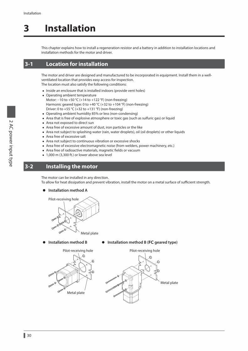
Installation
2 AC power input type
30
3 Installation
This chapter explains how to install a regeneration resistor and a battery in addition to installation locations and installation methods for the motor and driver.
3-1 Location for installation
The motor and driver are designed and manufactured to be incorporated in equipment. Install them in a well-ventilated location that provides easy access for inspection.The location must also satisfy the following conditions:
• Inside an enclosure that is installed indoors (provide vent holes) • Operating ambient temperature
Motor: −10 to +50 °C (+14 to +122 °F) (non-freezing) Harmonic geared type: 0 to +40 °C (+32 to +104 °F) (non-freezing) Driver: 0 to +55 °C (+32 to +131 °F) (non-freezing)
• Operating ambient humidity 85% or less (non-condensing) • Area that is free of explosive atmosphere or toxic gas (such as sulfuric gas) or liquid • Area not exposed to direct sun • Area free of excessive amount of dust, iron particles or the like • Area not subject to splashing water (rain, water droplets), oil (oil droplets) or other liquids • Area free of excessive salt • Area not subject to continuous vibration or excessive shocks • Area free of excessive electromagnetic noise (from welders, power machinery, etc.) • Area free of radioactive materials, magnetic fields or vacuum • 1,000 m (3,300 ft.) or lower above sea level
3-2 Installing the motor
The motor can be installed in any direction.To allow for heat dissipation and prevent vibration, install the motor on a metal surface of sufficient strength.
z Installation method A
Metal plate
Pilot-receiving hole
z Installation method B
Metal plate
Pilot-receiving hole
z Installation method B (FC geared type)
Pilot-receiving hole
Metal plate

Installation2 AC pow
er input type
31
TypeFrame size [mm (in.)]
Screw sizeTightening torque
[N·m (oz-in)]Effective depth of screw
thread [mm (in.)]Installation
method
Standard
42 (1.65) M3 1 (142) 4.5 (0.177) A
60 (2.36) M4 2 (280)− B
85 (3.35) M6 3 (420)
TH geared42 (1.65) 60 (2.36)
M4 2 (280) 8 (0.315)A
90 (3.54) M8 4 (560) 15 (0.591)
FC geared42 (1.65) M4 2 (280)
− B60 (2.36) M5 2.5 (350)
PS geared PN geared Harmonic geared *1
42 (1.65) M4 2 (280) 8 (0.315)
A60 (2.36) M5 2.5 (350) 10 (0.394)
90 (3.54) M8 4 (560) 15 (0.591)
Harmonic geared *2 90 (3.54) M8 4 (560) − B
*1 ARM46 and ARM66 type only.*2 ARM98 type only.
3-3 Installing a load
When installing a load to the motor, align the centers of the motor output shaft and load shaft. Flexible couplings are available as accessories.
• When coupling the load to the motor, pay attention to the centering of the shafts, belt tension, parallelism of the pulleys, and so on. Securely tighten the coupling and pulley set screws.
• Be careful not to damage the output shaft or bearings when installing a coupling or pulley to the motor output shaft.
• Do not modify or machine the motor output shaft. Doing so may damage the bearings (ball bearings) and destroy the motor.
• Do not apply strong force using hammer or other tools when removing the parallel key. Doing so may damage the motor output shaft and bearings (ball bearings).
z Using a couplingAlign the centers of the motor output shaft and load shaft in a straight line.
z Using a belt driveAlign the motor output shaft and load shaft in parallel with each other, and position both pulleys so that the line connecting their centers is at a right angle to the shafts.
z Using a gear driveAlign the motor output shaft and gear shaft in parallel with each other, and let the gears mesh at the center of the tooth widths.
• Using a coupling • Using a belt drive • Using a gear drive
z Using a parallel key (geared motor)When connecting the load and gear output shaft with a key slot, secure the load using the key included with the gear output shaft after machining the key slot on the load.

Installation
2 AC power input type
32
z Harmonic geared type; Installing the load on the flange surfaceWith a Harmonic geared type (excluding ARM98), a load can be installed directly to the gear using the load mounting holes provided on the flange surface.
Flange surface
Load mounting holes (6 places)
Motor modelScrew
sizeNumber of screw
Tightening torque
[N·m (oz-in)]
Effective depth of screw thread
[mm (in.)]
ARM46 M3 6 1.4 (198) 5 (0.197)
ARM66 M4 6 2.5 (350) 6 (0.236)
• When installing a load on the flange surface, the load cannot be mounted using the key slot in the output shaft.
• Design an appropriate installation layout so that the load will not contact the metal plate or screws used for installing the motor.
3-4 Permissible radial load and permissible axial load
• If the radial load or axial load exceeds the specified allowable value, repeated load applications may cause the bearing (ball bearings) or output shaft of the motor to undergo a fatigue failure.
• With a double shaft type, do not apply load torque, radial load, or axial load to the output shaft on the opposite side of the motor output shaft.
The permissible radial load and permissible axial load of the PS geared type and PN geared type represent the value that the service life of the gear part satisfies 20,000 hours when either of the radial load or axial load is applied to the gear output shaft.
Type Motor model Gear ratio
Permissible radial load [N (lb.)]Permissible axial
load [N (lb.)]Distance from the tip of motor output shaft [mm (in.)]
0 (0) 5 (0.2) 10 (0.39) 15 (0.59) 20 (0.79)
Standard
ARM46
−
35 (7.8) 44 (9.9) 58 (13) 85 (19.1) − 15 (3.3)
ARM66 ARM69
90 (20) 100 (22) 130 (29) 180 (40) 270 (60) 30 (6.7)
ARM98 ARM911
260 (58) 290 (65) 340 (76) 390 (87) 480 (108) 60 (13.5)
TH geared
ARM46All gear
ratio
10 (2.2) 14 (3.1) 20 (4.5) 30 (6.7) − 15 (3.3)
ARM66 70 (15.7) 80 (18) 100 (22) 120 (27) 150 (33) 40 (9)
ARM98 220 (49) 250 (56) 300 (67) 350 (78) 400 (90) 100 (22)
FC gearedARM46 All gear
ratio180 (40) 200 (45) 220 (49) 250 (56) − 100 (22)
ARM66 270 (60) 290 (65) 310 (69) 330 (74) 350 (78) 200 (45)
PS geared ARM46
5 70 (15.7) 80 (18) 95 (21) 120 (27) −
100 (22)
7.2 80 (18) 90 (20) 110 (24) 140 (31) −
10 85 (19.1) 100 (22) 120 (27) 150 (33) −
25 120 (27) 140 (31) 170 (38) 210 (47) −
36 130 (29) 160 (36) 190 (42) 240 (54) −
50 150 (33) 170 (38) 210 (47) 260 (58) −

Installation2 AC pow
er input type
33
Type Motor model Gear ratio
Permissible radial load [N (lb.)]Permissible axial
load [N (lb.)]Distance from the tip of motor output shaft [mm (in.)]
0 (0) 5 (0.2) 10 (0.39) 15 (0.59) 20 (0.79)
PS geared
ARM66
5 170 (38) 200 (45) 230 (51) 270 (60) 320 (72)
200 (45)
7.2 200 (45) 220 (49) 260 (58) 310 (69) 370 (83)
10 220 (49) 250 (56) 290 (65) 350 (78) 410 (92)
25 300 (67) 340 (76) 400 (90) 470 (105) 560 (126)
36 340 (76) 380 (85) 450 (101) 530 (119) 630 (141)
50 380 (85) 430 (96) 500 (112) 600 (135) 700 (157)
ARM98
5 380 (85) 420 (94) 470 (105) 540 (121) 630 (141)
600 (135)
7.2 430 (96) 470 (105) 530 (119) 610 (137) 710 (159)
10 480 (108) 530 (119) 590 (132) 680 (153) 790 (177)
25 650 (146) 720 (162) 810 (182) 920 (200) 1,070 (240)
36 730 (164) 810 (182) 910 (200) 1,040 (230) 1,210 (270)
50 820 (184) 910 (200) 1,020 (220) 1,160 (260) 1,350 (300)
PN geared
ARM46
5 80 (18) 95 (21) 120 (27) 160 (36) −
100 (22)7.2 90 (20) 110 (24) 130 (29) 180 (40) −
10 100 (22) 120 (27) 150 (33) 200 (45) −
ARM66
5 240 (54) 260 (58) 280 (63) 300 (67) 330 (74)
200 (45)
7.2 270 (60) 290 (65) 310 (69) 340 (76) 370 (83)
10 300 (67) 320 (72) 350 (78) 380 (85) 410 (92)
25 410 (92) 440 (99) 470 (105) 520 (117) 560 (126)
36 360 (81) 410 (92) 480 (108) 570 (128) 640 (144)
50 360 (81) 410 (92) 480 (108) 570 (128) 700 (157)
ARM98
5 370 (83) 390 (87) 410 (92) 430 (96) 460 (103)
600 (135)
7.2 410 (92) 440 (99) 460 (103) 490 (110) 520 (117)
10 460 (103) 490 (110) 520 (117) 550 (123) 580 (130)
25 630 (141) 660 (148) 700 (157) 740 (166) 790 (177)
36 710 (159) 750 (168) 790 (177) 840 (189) 900 (200)
50 790 (177) 840 (189) 890 (200) 940 (210) 1,000 (220)
Harmonic geared
ARM46All gear
ratio
180 (40) 220 (49) 270 (60) 360 (81) 510 (114) 220 (49)
ARM66 320 (72) 370 (83) 440 (99) 550 (123) 720 (162) 450 (101)
ARM98 1,090 (240) 1,150 (250) 1,230 (270) 1,310 (290) 1,410 (310) 1,300 (290)

Installation
2 AC power input type
34
Permissible moment load of the Harmonic geared typeIf an eccentric load is applied on the flange surface when installing an arm or a table, do not exceed the permissible value shown in the table.
Motor modelPermissible moment load
(N·m)
ARM46 5.6
ARM66 11.6
Use the calculating formula next for the moment load.
z Example 1; When an external force F is applied on the position of distance L from the center of the output flange
L: Distance from the center of the output flange (m)F: External force (N)
Moment load: M (N·m) = F × L
L
F
z Example 2; When external forces F is applied on the position of distance L from the mounting face of the output flange
L: Distance from the mounting face of the output flange (m)F: External force (N)
Moment load: M (N·m) = F × (L + coefficient "a")
LF
Motor model coefficient "a"
ARM46 0.009
ARM66 0.0114

Installation2 AC pow
er input type
35
3-5 Installing the driver
The driver is designed so that heat is dissipated via air convection and conduction through the enclosure. Install the driver on a flat metal plate [material: aluminium, 200×200×2 mm (7.87×7.87×0.08 in.) equivalent ] having excellent heat conductivity. When two or more drivers are to be installed side by side, provide 20 mm (0.79 in.) and 25 mm (0.98 in.) clearances in the horizontal and vertical directions, respectively.When installing the driver inside an enclosure, use two screws (M4, not included) to secure the driver through the mounting holes.
20 (0.79) or more150 (5.91)
25 (0.98) or more
35 (1.38)
Unit: mm (in.)
• Install the driver inside an enclosure whose pollution degree is 2 or better environment, or whose degree of protection is IP54 minimum.
• Do not install any equipment that generates a large amount of heat or noise near the driver.
• Do not install the driver underneath the controller or other equipment vulnerable to heat.
• If the ambient temperature of the driver exceeds 55 °C (131 °F), improve the ventilation condition.
• Be sure to install the driver vertically (vertical position).
Dimension [unit: mm (in.)]Mass: 0.75 kg (1.65 lb.)
ø4.5 (ø0.177) ThruSlits
2×M4Protective Earth Terminals Slits
125 (4.92)
5 (0.20)
[67 (2.64)] 19.5
(0.77)
5 (0
.20)
150
(5.9
1)
5 (0.20)35
(1.38)
R2.25 (0.089)
45(1.77)
160
(6.3
0)
17.5 (0.69)
10 (0.39)
8.1
(0.3
2)
0.5 (0.02)

Installation
2 AC power input type
36
3-6 Installing the regeneration resistor
Install the accessory regeneration resistor in a location where heat dissipation capacity equivalent to a level achieved with a heat sink [made of aluminum, 350×350×3 mm (13.78×13.78×0.12 in.)] is ensured.Affix the regeneration resistor on a smooth metal plate offering high heat conductivity, using two screws (M4, not included). Refer to p.51 for accessory.
Regeneration resistor
• Plate cutout for mounting [unit: mm (in.)]
Screws (M4)(not included)
165 (6.50)
ø4.2 +0.3 0 (ø0.1654 )+0.012
0
3-7 Installing the battery
A battery and battery holder are included in an accessory battery set BAT01B. Use the battery holder to secure the battery. Refer to p.52 for accessory.
M4
13±0.3(0.51±0.012)
Battery holder
Battery Plate cutout for mounting [unit: mm (in.)]
Screws (M4)(not included)

Connection2 AC pow
er input type
37
4 Connection
This chapter explains how to connect the motor, I/O signals and power supply to the driver, as well as grounding method. The installation and wiring methods in compliance with the EMC Directive as well as protection against noise are also explained.
• For protection against electric shock, do not turn on the power supply until the wiring is completed.
• A high voltage is applied to the motor connector (CN2) and the main power supply input terminal (CN3). Do not touch these terminals while the power is on. Doing so may result in fire or electric shock.
4-1 Connection example
The figure shows models for the electromagnetic brake motor and single-phase 200-240 VAC input.
Connect to CN2 *1
Connect to CN1 *1
Cable for motor *2
Cable for electromagnetic brake *2
24 VDC power supply
Connect to CN3
Output signalsConnect to CN9
Input signalsConnect to CN8
Sensor signalsConnect to CN5
Required
Required
Required
Grounding Grounding
Black (-)
CN1 connector
White (+)
24 VDCGND
MB1MB2
24 V+24 V-Connect to CN1
L
N
Main power supplySingle-phase 200-240 VAC
*1 Keep 30 m (98.4 ft.) or less for the wiring distance between the motor and driver.*2 Accessory.
• Have the connector plugged in securely. Insecure connections may cause malfunction or damage to the motor or driver.
• When cycling the power or plugging/unplugging the connector, turn off the power and wait for the CHARGE LED to turn off. The residual voltage may cause electric shock.
• Do not wire the power supply cable of the driver in the same cable duct with other power lines or motor cables. Doing so may cause malfunction due to noise.
• The lead wires of the "cable for electromagnetic brake" have polarities, so connect them in the correct polarities. If the lead wires are connected with their polarities reversed, the electromagnetic brake will not operate properly.
• When unplugging the connector, do so while pressing the latches on the connector. • When installing the motor on a moving part, use a flexible cable having excellent flex resistance. Refer to p.49 for details.

Connection
2 AC power input type
38
z Cable size and tightening torque
ConnectorTerminal symbol
Recommended cable size Screw sizeTightening torque
[N·m (oz-in)]
CN1
24V+, 24V− Stranded wire AWG28 to 16 (0.08 to 1.25 mm2)
M20.22 to 0.25
(31 to 35)TH1, TH2 Stranded wire AWG22 (0.3 mm2)
MB1, MB2 Stranded wire AWG20 (0.5 mm2)
CN3RG1, RG2 Stranded wire AWG18 (0.75 mm2)
− −L, N Stranded wire AWG16 to 14 (1.25 to 2.0 mm2)
CN5 − Stranded wire AWG26 to 20 (0.14 to 0.5 mm2) − −
CN8 − Stranded wire AWG26 to 20 (0.14 to 0.5 mm2) − −
CN9 − Stranded wire AWG26 to 20 (0.14 to 0.5 mm2) − −
4-2 Grounding the motor and driver
Grounding the motorBe sure to ground the Protective Earth Terminal of the motor.
• Grounding wire: AWG18 (0.75 mm2) or more • Screw size: M4 • Tightening torque: 1.2 N·m (170 oz-in)
Use a round terminal when grounding, and secure it with a mounting screw with a washer. Ground wires and crimp terminals are not included.
Grounding
Protective Earth Terminal
Grounding the driverBe sure to ground the Protective Earth Terminal of the driver.
• Grounding wire: AWG16 to 14 (1.25 to 2.0 mm2) • Screw size: M4 • Tightening torque: 1.2 N·m (170 oz-in)
You can ground either of the two Protective Earth Terminals. The terminal that is not grounded is used as a service terminal. Use the service terminal according to your specific need, such as connecting it to the motor in order to ground the motor.Do not share the grounding wire with a welder or any other power equipment.When grounding the Protective Earth Terminal, use a round terminal and secure the grounding point near the driver.
Protective Earth Terminals(Ground one of these terminals.) Grounding

Connection2 AC pow
er input type
39
4-3 Connecting the main power supply
Use the CN3 connector (5 pins) to connect the power supply cable (AWG16 to 14: 1.25 to 2.0 mm2) to the main power supply connector (CN3) on the driver.
Single-phase 100-120 VACSingle-phase 200-240 VAC
50/60 Hz
CN3 connector
Single-phase100-120 VAC
Single-phase200-240 VAC
LN
• Do not wire the power supply cable of the driver in the same cable duct with other power lines or motor cables. Doing so may cause malfunction due to noise.
• When cycling the power or plugging/unplugging the connector, turn off the power and wait for the CHARGE LED to turn off. The residual voltage may cause electric shock.
Wiring method
Strip gauge
Applicable lead wire: AWG16 to 14 (1.25 to 2.0 mm2)Stripping length of wire insulation: 8 to 9 mm (0.31 to 0.35 in.)
1. Strip o the wire insulation based on the strip gauge.
2. Push the connector wiring lever in the direction of the arrow.
3. Insert the lead wire.
You can also connect the power supply cable using a slotted screwdriver.Insert the lead wire while pushing the insertion port using a slotted screwdriver with a tip of 3.0 to 3.5 mm (0.12 to 0.14 in.) in width.
Insert the lead wire while pushing down the slotted screwdriver.
Slotted screwdriverinsertion port
Power supply current capacity
Motor modelSingle-phase 100-120 V −15 to +6% 50/60 Hz
Single-phase 200-240 V −15 to +6% 50/60 Hz
ARM46 2.4 A or more 1.5 A or more
ARM66 3.6 A or more 2.3 A or more
ARM69 4.9 A or more 3.0 A or more
ARM98 4.6 A or more 2.9 A or more
ARM911 5.9 A or more 3.7 A or more

Connection
2 AC power input type
40
4-4 Connecting the 24 VDC power supply, regeneration resistor and electromagnetic brake
Use the CN1 connector (6 pins) to connect the 24 VDC power supply, regeneration resistor and electromagnetic brake. Connect the lead wire (AWG28 to 16: 0.08 to 1.25 mm2) to the connector while checking the pin numbers in below.
Display Description
24V+24 VDC power supply input
24V−
TH1 Regeneration resistor thermal input (If these pins are not used, short it using a jumper wire.)TH2
MB1Electromagnetic brake − (Connect the black lead wire of the electromagnetic brake.)
MB2Electromagnetic brake + (Connect the white lead wire of the electromagnetic brake.)
Connecting method
1. Strip the insulation cover of the lead wire by 7 mm (0.28 in.)
2. Insert each lead wire into the CN1 connector and tighten the screw with a slotted screwdriver.Connector screw size: M2Tightening torque: 0.22 to 0.25 N·m (31 to 35 oz-in)
3. Insert the CN1 connector into the CN1, and tighten the screw.Connector screw size: M2.5Tightening torque: 0.4 N·m (56 oz-in)
7 mm(0.28 in.)
Lead wires
CN1 connector
CN1
Slotted screwdriver
Connecting the 24 VDC power supplyThe 24 VDC power supply is for the control circuit of the driver. Use the 24 VDC power supply of the following capacity.
Motor model Input power supply voltagePower supply current capacity
Without electromagnetic brake With electromagnetic brake
ARM46
24 VDC±5% * 0.25 A or more
0.33 A or more
ARM66 ARM69 ARM98
0.5 A or more
ARM911 −
* If the distance between the motor and driver is extended to 20 to 30 m (65.6 to 98.4 ft.), use a power supply of 24 VDC±4%.
When cycling the 24 VDC power supply, turn off the power and wait for at least 1 second before turning on.

Connection2 AC pow
er input type
41
Connecting the regeneration resistorIf vertical drive (gravitational operation) such as elevator applications is performed or if sudden start-stop operation of a large inertial load is repeated frequently, connect an accessory regeneration resistor.
Regeneration resistor
AWG22
CN1To TH1 and TH2 terminals
150 °C (302 °F)[norm
ally closed]
CN3To RG1 and RG2 terminalsAWG18
R: 150 Ω
• The two thin lead wires (AWG22: 0.3 mm2) of the regeneration resistor are the thermostat outputs. Connect them to the TH1 and TH2 terminals using the CN1 connector.
• Regenerative current flows through the two thick lead wires (AWG18: 0.75 mm2) of the regeneration resistor. Connect them to the RG1 and RG2 terminals using the CN3 connector.
• Before connecting the regeneration resistor, be sure to remove the jumper wire from the CN1 connector.
• If the allowable power consumption of the regeneration resistor exceeds the allowable level, the thermostat will be triggered and a regeneration resistor overheat alarm of the driver is generate. If a regeneration resistor overheat alarm generates, turn off the main power supply and check the content of the error.
Regeneration resistor specifications
Model RGB100
Allowable current consumptionContinuous regenerative power: 50 W * Instantaneous regenerative power: 600 W
Resistance 150 Ω
Operating temperature of thermostatOperation: Opens at 150±7 °C (302±12.6 °F) Reset: Closes at 145±12 °C (293±21.6 °F) (normally closed)
Electrical rating of thermostat 120 VAC 4 A, 30 VDC 4 A (minimum current: 5 mA)
* Install the regeneration resistor in a location where heat dissipation capacity equivalent to a level achieved with a heat sink [made of aluminum, 350×350×3 mm (13.78×13.78×0.12 in.)] is ensured.
Connecting the electromagnetic brakeWhen the electromagnetic brake is connected, it can automatically be controlled by interlocking with the C-ON input or the FREE input. Refer to p.37 for connection method.

Connection
2 AC power input type
42
4-5 Connecting the I/O signals
Wiring method • Applicable lead wire: AWG26 to 20 (0.14 to 0.5 mm2) • Stripping length of wire insulation: 8 mm (0.32 in.)
1. Strip the insulation cover of the lead wire.
2. Insert the lead wire while pushing the button of the orange color on the connector with a slotted screwdriver.
3. After having inserted, release the button to secure the lead wire.
Button of the orange color
Lead wire
Pin assignment
z Sensor signals (CN5)
Pin No. Signal name Description
1
5
···
1 +LS Limit sensor input +
2 −LS Limit sensor input −
3 HOMES Mechanical home sensor input
4 SLIT Slit sensor input
5 IN-COM2 Sensor signals common
z Input signals (CN8)
Pin No. Signal name Description *
1
9
·····
1 IN0 Control input 0 (HOME)
2 IN1 Control input 1 (START)
3 IN2 Control input 2 (M0)
4 IN3 Control input 3 (M1)
5 IN4 Control input 4 (M2)
6 IN5 Control input 5 (FREE)
7 IN6 Control input 6 (STOP)
8 IN7 Control input 7 (ALM-RST)
9 IN-COM1 Input signals common
* ( ): Initial value
z Output signals (CN9)
Pin No. Signal name Description *
1
7
····
1 OUT0 Control output 0 (HOME-P)
2 OUT1 Control output 1 (END)
3 OUT2 Control output 2 (AREA1)
4 OUT3 Control output 3 (READY)
5 OUT4 Control output 4 (WNG)
6 OUT5 Control output 5 (ALM)
7 OUT-COM Output signals common
* ( ): Initial value

Connection2 AC pow
er input type
43
Connection example with a current sink output circuit (NPN specifications)
1
2
3
4
5
6
7
1
2
3
4
5
6
7
8
9
1
2
3
4
5
DriverController
24 VDC
12 to 24 VDC
Output saturated voltage3 V max.
OUT0 (HOME-P)CN9
IN0 (HOME)
IN1 (START)
IN2 (M0)
IN3 (M1)
IN4 (M2)
IN-COM1
IN7 (ALM-RST)
IN6 (STOP)
IN5 (FREE)
CN8
+LS
( ): Initial value
-LS
HOMES
SLIT
IN-COM2
CN5
OUT1 (END)
OUT2 (AREA1)
OUT3 (READY)
OUT4 (WNG)
OUT5 (ALM)
OUT-COM
4.4 kΩ
4.4 kΩ1 kΩ
1 kΩ
1 kΩ
1 kΩ
1 kΩ
1 kΩ
1 kΩ
1 kΩ
4.4 kΩ
4.4 kΩ
4.4 kΩ
4.4 kΩ
4.4 kΩ
4.4 kΩ
1 kΩ
1 kΩ
1 kΩ
1 kΩ
4.4 kΩ
4.4 kΩ
4.4 kΩ
4.4 kΩ
R0
R0
R0
R0
R0
R0
24 VDC
0 V
0 V
0 V
NPN sensor
10 mA or less
• Use input signals at 24 VDC. • Use output signals at 12 to 24 VDC 10 mA or less. If the current exceeds 10 mA, connect an external resistor R0 so that the current becomes 10 mA or less.
• The saturated voltage of the output signal is 3 VDC maximum.

Connection
2 AC power input type
44
Connection example with a current source output circuit (PNP specifications)
1
2
3
4
5
6
7
89
1
2
3
4
5
6
7
1
2
3
4
5
Controller
24 VDC
12 to 24 VDC
Output saturated voltage3 V max.
CN9
CN8
CN5
4.4 kΩ
4.4 kΩ1 kΩ
1 kΩ
1 kΩ
1 kΩ
1 kΩ
1 kΩ
1 kΩ
1 kΩ
4.4 kΩ
4.4 kΩ
4.4 kΩ
4.4 kΩ
4.4 kΩ
4.4 kΩ
1 kΩ
1 kΩ
1 kΩ
1 kΩ
4.4 kΩ
4.4 kΩ
4.4 kΩ
4.4 kΩ
R0
R0
R0
R0
R0
R0
24 VDC
0 V
0 V
0 V
PNP sensor
OUT0 (HOME-P)
IN0 (HOME)
IN1 (START)
IN2 (M0)
IN3 (M1)
IN4 (M2)
IN-COM1IN7 (ALM-RST)
IN6 (STOP)
IN5 (FREE)
+LS
( ): Initial value
-LS
HOMES
SLIT
IN-COM2
OUT1 (END)
OUT2 (AREA1)
OUT3 (READY)
OUT4 (WNG)
OUT5 (ALM)
OUT-COM
10 mA or less
Driver
• Use input signals at 24 VDC. • Use output signals at 12 to 24 VDC 10 mA or less. If the current exceeds 10 mA, connect an external resistor R0 so that the current becomes 10 mA or less.
• The saturated voltage of the output signal is 3 VDC maximum.

Connection2 AC pow
er input type
45
4-6 Connecting the data setter
Connect the communication cable for the support software or OPX-2A cable to the data edit connector (CN4) on the driver. Connect to CN4
Communication cable for the support software or OPX-2A cable
The data edit connector (CN4) and RS-485 communication connectors (CN6/CN7) of the driver are not insulated. When grounding the positive terminal of the power supply, do not connect any equipment (PC, etc.) whose negative terminal is grounded. Doing so may cause the driver and these equipment to short, damaging both.
4-7 Connecting the RS-485 communication cable
Connect this cable if you want to control your product via RS-485 communication. Connect the RS-485 communication cable to CN6 or CN7 on the driver.You can use the vacant connectors to connect a different driver. A driver link cable is available as an accessory. See p.51. You can also use a commercial LAN cable (straight cable) to link drivers.
RS-485 communicationconnectors (CN6/CN7)
Drivers can be linked.
• Internal input circuit
2 GND3 TR+
6 TR-
2 GND3 TR+
6 TR-120 Ω
1 kΩ
1 kΩ
5 V
0 V0 V
TERM.No.2
TERM.No.1
CN6/CN7 pin assignment
Pin No. Signal name Description
1
8
···
1 N.C. Not used.
2 GND GND
3 TR+ RS-485 communication signal (+)
4 N.C.Not used.
5 N.C.
6 TR− RS-485 communication signal (−)
7 N.C.Not used.
8 N.C.

Connection
2 AC power input type
46
4-8 Connecting and charging the battery
Connect an accessory battery set when using in the absolute-position backup system.When the battery is connected to the battery connector (CN10) of the driver and the 24 VDC power is turned on, the battery will start charging. It takes approximately 32 hours to fully charge the battery [at an ambient temperature of 20 °C (68 °F)]. Refer p.52 for accessory.Refer to p.164 for setting method of the absolute-position backup system.
Battery power supply GNDBattery power supply inputNot used
Battery specifications
Battery type Sealed nickel-metal hydride battery
Nominal voltage 2.4 V
Rated capacity 1,900 mAh
Mass 0.10 kg (3.5 oz)
Expected life Approximately 4 years *1
Charging time 32 hours *1
Data retention period Approximately 360 hours (Approximately 15 days) *1 *2
Ambient temperature 0 to +40 °C (+32 to +104 °F) (non-freezing)
Ambient humidity 45 to 85% (non-condensing)
*1 At an ambient temperature of 20 °C (68 °F)*2 After the power is cut off with the battery fully charged.
4-9 Noise measures
The electrical noise is of two types: One is a noise to invade into the driver from the outside and cause the driver malfunction, and the other is a noise to emit from the driver and cause peripheral equipments malfunction.For the noise that is invaded from the outside, take measures to prevent the driver malfunction. It is needed to take adequate measures because signal lines are very likely to be affected by the noise.For the noise that is emitted from the driver, take measures to suppress it.
Measures against electrical noiseThere are the following three methods mainly to take measures against the electrical noise.
z Noise suppression • When relays or electromagnetic switches are used together with the system, use noise filters and CR circuits to
suppress surges generated by them. • Use an accessory cable when extending a wiring distance between the motor and driver. • Cover the driver by a metal plate such as aluminum. This is effective in shielding the electrical noise emitted from
the driver.
z Prevention of noise propagation • Connect a noise filter in the power supply cable of driver. • Place the power lines, such as the motor and power supply cables, keeping a distance of 200 mm (7.87 in.) or more
from the signal lines, and also do not bundle them or wire them in parallel. If the power cables and signal cables have to cross, cross them at a right angle.
• Use shielded twisted pair cables for power lines and signal lines. • Keep cables as short as possible without coiling and bundling extra lengths. • Grounding multiple points will increase effect to block electrical noise because impedance on the grounding
points is decreased. However, ground them so that a potential difference does not occur among the grounding points. An accessory driver cable including with a ground wire is available. Refer to p.51 for details.
• To ground a shielded cable, use a metal cable clamp that will maintain contact with the entire circumference of the cable. Ground the cable clamp near the product.
Cable clampShielded cable

Connection2 AC pow
er input type
47
z Suppression of effect by noise propagationLoop the noise propagated cable around a ferrite core. Doing so will prevent the propagated noise invades into the driver or emits from the driver. The frequency band in which an effect by the ferrite core can be seen is generally 1 MHz or more. Check the frequency characteristics of the ferrite core used. To increase the effect of noise attenuation by the ferrite core, loop the cable a lot.
Noise suppression parts
z Noise filter • Connect the following noise filter (or equivalent) to the power line. Doing so will prevent the propagated noise
through the power line. Install the noise filter as close to the driver as possible.
Manufacture Model
SOSHIN ELECTRIC CO.,LTD HF2010A-UPF
Schaffner EMC FN2070-10-06
• Use the AWG18 (0.75 mm2) or thicker wire for the input and output cables of the noise filter, and secure firmly using a cable clamp etc. so that the cable does not come off the enclosure.
• Place the input cable as far apart as possible from the output cable, and do not wire the cables in parallel. If the input and output cable are placed at a close distance or if they are wired in parallel, the noise inside the enclosure affects the power cable through stray capacitance, and the noise suppressing effect will reduce.
• Connect the ground terminal of the noise filter to the grounding point, using as thick and short a wire as possible. • When connecting a noise filter inside an enclosure, wire the input cable of the noise filter as short as possible.
Wiring in long distance may reduce the noise suppressing effect.
z Surge arresterA surge arrester is effective for reduction of the surge voltage of the lightning surge generated between the AC power line and earth or between AC power lines. Connect the following surge arrester.R·A·V-781BWZ-4 (OKAYA ELECTRIC INDUSTRIES CO., LTD.)
When measuring dielectric strength of the equipment, be sure to remove the surge arrester, or the surge arrester may be damaged.
Noise suppression parts (accessories)Refer to p.51 for accessories.
z Driver cableThis cable is a shielded twisted pair cable for good noise immunity to connect the driver and controller. The ground wires useful to grounding are provided at both ends of the cable. The EMC measures are conducted using the Oriental Motor driver cable.
z Surge suppressorThis product is effective to suppress the surge which occurs in a relay contact part. Connect it when using a relay or electromagnetic switch. CR circuit for surge suppression and CR circuit module are provided.
4-10 Conformity to the EMC Directive
Effective measures must be taken against the EMI that the motor and driver may give to adjacent control-system equipment, as well as the EMS of the motor and driver itself, in order to prevent a serious functional impediment in the machinery. The use of the following installation and wiring methods will enable the motor and driver to be compliant with the EMC Directive. Refer to p.322 for the applicable standards.Oriental Motor conducts EMC measurements on its motors and drivers in accordance with “Example of motor and driver installation and wiring” on p.48.The user is responsible for ensuring the machine's compliance with the EMC Directive, based on the installation and wiring explained below.
z Connecting noise filterIn large electrically noisy environments, connect a noise filter. Refer to “Noise filter” in the above.
z Connecting surge arresterRefer to “Surge arrester” in the above.

Connection
2 AC power input type
48
z Connecting the 24 VDC power supplyUse a 24 VDC power supply that conforms to the EMC Directive.Use a shielded twisted pair cable for wiring. Refer to “Prevention of noise propagation” on p.46 for wiring method.
z Connecting the motor cableUse an accessory motor cable when extending the wiring distance between the motor and driver.
z Connecting the signal cableRefer to “Prevention of noise propagation” on p.46.
z How to ground • The cable used to ground the motor, driver and noise filter must be as thick and short as possible so that no
potential difference is generated. • Choose a large, thick and uniformly conductive surface for the grounding point. • Be sure to ground the Protective Earth Terminal of the motor and driver. Refer to p.38 for grounding method.
z Example of motor and driver installation and wiring
Motor
Controller
Sensor
A: Cable clamp
DriverShieldedcable
Shielded cable
RS-485communication cable
Motor cable(shielded cable)
Grounded panel
OPX-2A
Battery
Noiselter
24 VDCpower
Surgearrester
Noiselter
AC
AC
A
A
A
A
Grounding
Grounding
Grounding
Grounding Grounding
Grounding
Grounding
Grounding
Grounding
Grounding
Grounding
Shielded cable
The driver uses parts that are sensitive to electrostatic charge. Take measures against static electricity since static electricity may cause the driver to malfunction or suffer damage.

Accessories2 AC pow
er input type
49
5 Accessories
5-1 Motor cable set
When installing the motor on a moving part, use a flexible cable having excellent flex resistance.
Connection cable setUse when connecting a motor and a driver. The cable set for electromagnetic brake motors consists of two cables, one for motor and the other for electromagnetic brake.
For motor
Connection cable set
For electromagnetic brake *
* Only when the motor is of electromagnetic brake type.
z Connection cable set model z Flexible connection cable set model
Length [m (ft.)]
For standard type motor
For electromagnetic brake type motor
Length [m (ft.)]
For standard type motor
For electromagnetic brake type motor
0.5 (1.6) CC005VAF CC005VAFB 0.5 (1.6) CC005VAR CC005VARB
1 (3.3) CC010VAF CC010VAFB 1 (3.3) CC010VAR CC010VARB
1.5 (4.9) CC015VAF CC015VAFB 1.5 (4.9) CC015VAR CC015VARB
2 (6.6) CC020VAF CC020VAFB 2 (6.6) CC020VAR CC020VARB
2.5 (8.2) CC025VAF CC025VAFB 2.5 (8.2) CC025VAR CC025VARB
3 (9.8) CC030VAF CC030VAFB 3 (9.8) CC030VAR CC030VARB
4 (13.1) CC040VAF CC040VAFB 4 (13.1) CC040VAR CC040VARB
5 (16.4) CC050VAF CC050VAFB 5 (16.4) CC050VAR CC050VARB
7 (23) CC070VAF CC070VAFB 7 (23) CC070VAR CC070VARB
10 (32.8) CC100VAF CC100VAFB 10 (32.8) CC100VAR CC100VARB
15 (49.2) CC150VAF CC150VAFB 15 (49.2) CC150VAR CC150VARB
20 (65.6) CC200VAF CC200VAFB 20 (65.6) CC200VAR CC200VARB
30 (98.4) CC300VAF CC300VAFB 30 (98.4) CC300VAR CC300VARB

Accessories
2 AC power input type
50
Extension cable setUse when extending the distance between a motor and a driver or when the length of the connection cable used is not enough. Extend the distance by connecting the extension cable to the connection cable.The cable set for electromagnetic brake motors consists of two cables, one for motor and the other for electromagnetic brake.
For motor
Extension cable set
For electromagnetic brake *2
For motor
For electromagnetic brake *2
Connection cable set *1
*1 Use the connection cable used.*2 Only when the motor is of electromagnetic brake type.
When extending the wiring length by connecting an extension cable to the connection cable, keep the total cable length to 30 m (98.4 ft.) or less.
z Extension cable set model z Flexible extension cable set model
Length [m (ft.)]
For standard type motor
For electromagnetic brake type motor
Length [m (ft.)]
For standard type motor
For electromagnetic brake type motor
0.5 (1.6) CC005VAFT CC005VAFBT 0.5 (1.6) CC005VART CC005VARBT
1 (3.3) CC010VAFT CC010VAFBT 1 (3.3) CC010VART CC010VARBT
1.5 (4.9) CC015VAFT CC015VAFBT 1.5 (4.9) CC015VART CC015VARBT
2 (6.6) CC020VAFT CC020VAFBT 2 (6.6) CC020VART CC020VARBT
2.5 (8.2) CC025VAFT CC025VAFBT 2.5 (8.2) CC025VART CC025VARBT
3 (9.8) CC030VAFT CC030VAFBT 3 (9.8) CC030VART CC030VARBT
4 (13.1) CC040VAFT CC040VAFBT 4 (13.1) CC040VART CC040VARBT
5 (16.4) CC050VAFT CC050VAFBT 5 (16.4) CC050VART CC050VARBT
7 (23) CC070VAFT CC070VAFBT 7 (23) CC070VART CC070VARBT
10 (32.8) CC100VAFT CC100VAFBT 10 (32.8) CC100VART CC100VARBT
15 (49.2) CC150VAFT CC150VAFBT 15 (49.2) CC150VART CC150VARBT
20 (65.6) CC200VAFT CC200VAFBT 20 (65.6) CC200VART CC200VARBT

Accessories2 AC pow
er input type
51
5-2 Setting tool
Communication cable for the support softwareBe sure to purchase the communication cable for the support software when connecting a driver and PC in which the support software MEXE02 has been installed.This is a set of a PC interface cable and USB cable. The cable is connected to the USB port on the PC.
Model: CC05IF-USB [5 m (16.4 ft.)]
The MEXE02 can be downloaded from Oriental Motor Website Download Page. Also, the MEXE02 is provided in the form of a storage medium. For details, check out our web site or contact your nearest Oriental Motor sales office.
Data setterThe data setter lets you set operation data and parameters for your AR Series with ease and also functions as a monitor.
Model: OPX-2A
5-3 Wiring support tool
RS-485 communication cableYou can link drivers using this cable connected to the RS-485 communication connectors (CN6, CN7).
Model: CC002-RS4 [0.25 m (1 ft.)]
Regeneration resistorIf vertical drive (gravitational operation) such as elevator applications is performed or if sudden start-stop operation of a large inertial load is repeated frequently, connect the regeneration resistor. Always connect the regeneration resistor if an overvoltage protection warning or alarm generates.
Model: RGB100
Driver cableA shielded cable for driver control I/O signals offering excellent noise resistance. The ground wires useful to grounding are provided at both ends of the cable.Select the cable suitable for the number of I/O signals connected.
Driver cable model list
Cable length [m (ft.)]
Number of lead wire
6 pcs. 10 pcs. 12 pcs. 16 pcs.
0.5 (1.6) CC06D005B-1 CC10D005B-1 CC12D005B-1 CC16D005B-1
1 (3.3) CC06D010B-1 CC10D010B-1 CC12D010B-1 CC16D010B-1
1.5 (4.9) CC06D015B-1 CC10D015B-1 CC12D015B-1 CC16D015B-1
2 (6.6) CC06D020B-1 CC10D020B-1 CC12D020B-1 CC16D020B-1
CR circuit for surge suppressionThis product is effective to suppress the serge which occurs in a relay contact part. Use it to protect the contacts of the relay or switch.
Model: EPCR1201-2
CR circuit moduleThis product is effective to suppress the surge which occurs in a relay contact part. Use this product to protect the contacts of the relay or switch.Four pieces of CR circuit for surge suppression are mounted on the compact circuit, and this product can be installed to the DIN rail. This product can make the wiring easily and securely since it also supports terminal block connection.
Model: VCS02

Accessories
2 AC power input type
52
5-4 Others
Battery setThis is a battery set (including a battery and battery holder) required in the absolute-position backup system.
Model: BAT01B

3 DC power input type
This part explains contents specific to the AR Series DC power input type.
Table of contents
1 System configuration ............................ 54
2 Preparation ............................................. 552-1 Checking the product ................................... 552-2 How to identify the product model ......... 562-3 Information about nameplate ................... 572-4 Combinations of motors and drivers ....... 582-5 Input/output power ratings ........................ 592-6 Names and functions of parts .................... 59
3 Installation .............................................. 623-1 Location for installation ................................ 623-2 Installing the motor ....................................... 623-3 Installing a load ............................................... 633-4 Permissible radial load and
permissible axial load .................................... 643-5 Installing the driver ........................................ 673-6 Installing the battery ..................................... 68
4 Connection ............................................. 694-1 Connection example ..................................... 694-2 Grounding the motor and driver .............. 704-3 Connecting the power supply and
electromagnetic brake.................................. 714-4 Connecting the I/O signals .......................... 724-5 Connecting the data setter ......................... 754-6 Connecting the RS-485 communication
cable .................................................................... 754-7 Connecting and charging the battery .... 764-8 Noise measures ............................................... 764-9 Conformity to the EMC Directive .............. 77
5 Accessories.............................................. 795-1 Motor cable set ................................................ 795-2 Setting tool ....................................................... 815-3 Wiring support tool ........................................ 825-4 Others ................................................................. 82

System configuration
3 DC pow
er input type
54
1 System configuration
Connect to CN3
Connect to CN2
Use a noise lter to eliminate noise. It has the eect of reducing noise generated from the power supply and driver.
AC powersupply
DC powersupply
Cable for motor *2 *3This cable is used to connect the motor and driver.
Motor cable
Grounding
Grounding
OPX-2A *2
Or
PC in which the MEXE02has been installed. *1
Motor
Driver
Noiselter
Master controller
Sensor signals: Connect to CN5
Output signals: Connect to CN9
Input signals: Connect to CN8
Master controllerConnect when controlling the system via RS-485 communication.
Connect to CN4
Battery *2Connect this battery if you want to operate the driver in the absolutebackup system.
24 VDCGND
*1 The PC must be supplied by the user. Use the accessory communication cable for the support software when connecting the PC and driver.
*2 Accessory.*3 Use the cable for motor when the length of the motor cable is not enough.

Preparation3 D
C power input type
55
2 Preparation
This chapter explains the items you should check, as well as the name and function of each part.
2-1 Checking the product
Verify that the items listed below are included. Report any missing or damaged items to the Oriental Motor sales office from which you purchased the product.
z Motor • Motor ........................................................................1 unit • Parallel key ..............................................................1 pc. *1 • Varistor .....................................................................1 pc. *2 • OPERATING MANUAL Motor ............................1 copy • APPENDIX UL Stndards for AR Series ............1 copy *3
*1 Included with geared types. However, the following geared types are excluded. TH geared: ARM24-T, ARM46-T, and ARM66-T PS geared: ARM24-PS PN geared: ARM24-N Harmonic geared: ARM24-H
*2 Included with the electromagnetic brake motor of DC power input type.*3 Included with products conform to the UL Standards.
z Driver • Driver ........................................................................1 unit • CN1 connector (5 pins) .......................................1 pc. • CN5 connector (5 pins) .......................................1 pc. • CN8 connector (9 pins) .......................................1 pc. • CN9 connector (7 pins) .......................................1 pc. • OPERATING MANUAL Driver ............................1 copy • APPENDIX UL Stndards for AR Series ............1 copy *
* Included with products conform to the UL Standards.
Included connector model
Type Model number Manufacturer
CN1 connector MC1,5/5-STF-3,5 PHOENIX CONTACT GmbH & Co. KG
CN5 connector FK-MC0,5/5-ST-2,5 PHOENIX CONTACT GmbH & Co. KG
CN8 connector FK-MC0,5/9-ST-2,5 PHOENIX CONTACT GmbH & Co. KG
CN9 connector FK-MC0,5/7-ST-2,5 PHOENIX CONTACT GmbH & Co. KG
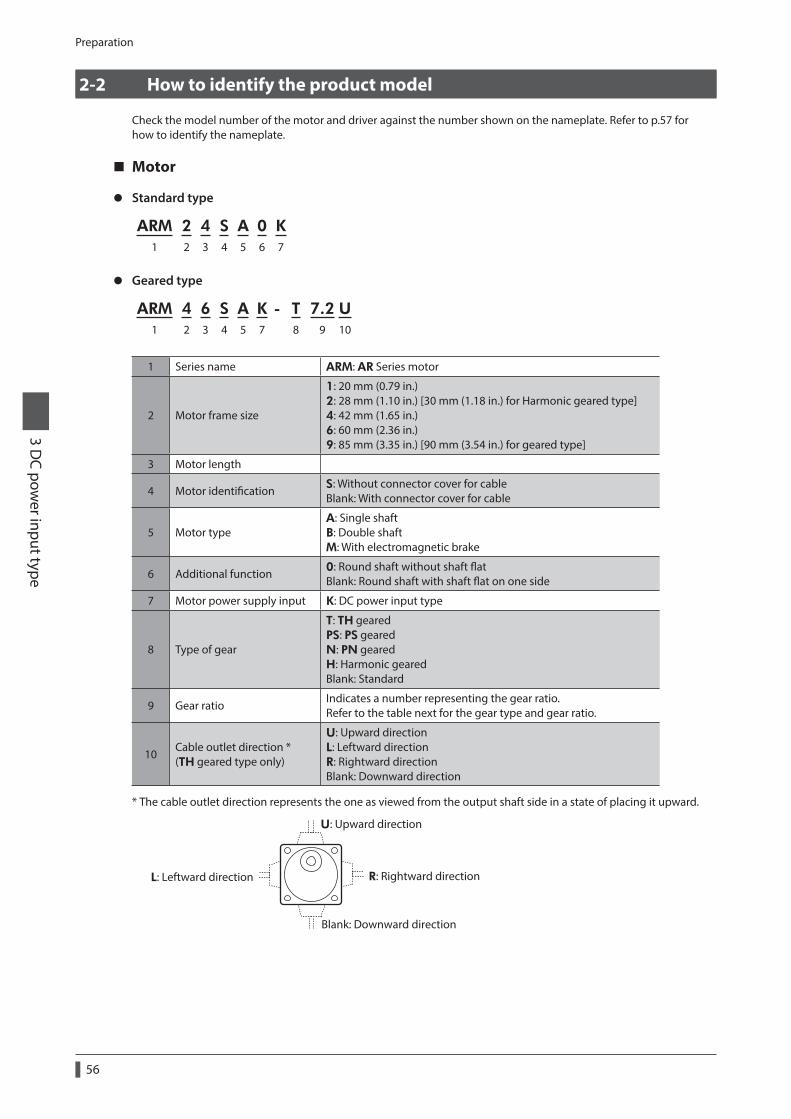
Preparation
3 DC pow
er input type
56
2-2 How to identify the product model
Check the model number of the motor and driver against the number shown on the nameplate. Refer to p.57 for how to identify the nameplate.
Motor
z Standard type
ARM 2 4 S A 0 K1 2 3 4 5 6 7
z Geared type
ARM 4 6 S A K - T 7.2 U1 2 3 4 5 7 8 9 10
1 Series name ARM: AR Series motor
2 Motor frame size
1: 20 mm (0.79 in.) 2: 28 mm (1.10 in.) [30 mm (1.18 in.) for Harmonic geared type] 4: 42 mm (1.65 in.) 6: 60 mm (2.36 in.) 9: 85 mm (3.35 in.) [90 mm (3.54 in.) for geared type]
3 Motor length
4 Motor identification S: Without connector cover for cable Blank: With connector cover for cable
5 Motor typeA: Single shaft B: Double shaft M: With electromagnetic brake
6 Additional function 0: Round shaft without shaft flat Blank: Round shaft with shaft flat on one side
7 Motor power supply input K: DC power input type
8 Type of gear
T: TH geared PS: PS geared N: PN geared H: Harmonic geared Blank: Standard
9 Gear ratioIndicates a number representing the gear ratio. Refer to the table next for the gear type and gear ratio.
10Cable outlet direction * (TH geared type only)
U: Upward direction L: Leftward direction R: Rightward direction Blank: Downward direction
* The cable outlet direction represents the one as viewed from the output shaft side in a state of placing it upward.
U: Upward direction
R: Rightward directionL: Leftward direction
Blank: Downward direction

Preparation3 D
C power input type
57
Type of gear ratio
Type of gear Gear ratio
TH geared ARM24: 7.2, 10, 20, 30 ARM46, ARM66, ARM98: 3.6, 7.2, 10, 20, 30
PS geared ARM24: 5, 7.2 (*), 10 ARM46, ARM66, ARM98: 5, 7.2 (*), 10, 25, 36, 50
PN geared ARM24, ARM46: 5, 7.2, 10 ARM66, ARM98: 5, 7.2, 10, 25, 36, 50
Harmonic geared 50, 100
* The model name is "7" for the gear ratio 7.2 of the PS geared type.
Driver
ARD - K D1 2 3
1 Series name ARD: AR Series driver
2 Power supply input K: 24 VDC/48 VDC
3 Type D: Built-in controller type
2-3 Information about nameplate
The figure shows an example.
Motor model
Serial number Manufacturing date
Specication
Driver modelInput specication
Output specication
Serial number Manufacturing date
The position describing the information may vary depending on the product.

Preparation
3 DC pow
er input type
58
2-4 Combinations of motors and drivers
Standard type
Single shaft Double shaft With electromagnetic brake
Motor model Driver model Motor model Driver model Motor model Driver model
ARM14SAK
ARD-KD
ARM14SBK
ARD-KD
ARM24SMK
ARD-KD
ARM14SA0K ARM14SB0K ARM24SM0K
ARM15SAK ARM15SBK ARM26SMK
ARM15SA0K ARM15SB0K ARM26SM0K
ARM24SAK ARM24SBK ARM46SMK
ARM24SA0K ARM24SB0K ARM46SM0K
ARM26SAK ARM26SBK ARM46MK
ARM26SA0K ARM26SB0K ARM66SMK
ARM46SAK ARM46SBK ARM66SM0K
ARM46SA0K ARM46SB0K ARM66MK
ARM46AK ARM46BK ARM69SMK
ARM66SAK ARM66SBK ARM69SM0K
ARM66SA0K ARM66SB0K ARM69MK
ARM66AK ARM66BK ARM98SMK
ARM69SAK ARM69SBK ARM98SM0K
ARM69SA0K ARM69SB0K ARM98MK
ARM69AK ARM69BK
ARM98SAK ARM98SBK
ARM98SA0K ARM98SB0K
ARM98AK ARM98BK
Geared type • The box (z) in the model name indicates a number representing the gear ratio. • The box () in the model name indicates U (upward direction), L (left direction), or R (right direction) representing
the cable outlet direction. The box () is blank when the cable outlet direction is downward.
Type of gearSingle shaft With electromagnetic brake
Motor model Driver model Motor model Driver model
TH geared
ARM24SAK-Tz
ARD-KD
ARM24SMK-Tz
ARD-KD
ARM46SAK-Tz ARM46SMK-Tz
ARM46AK-Tz ARM46MK-Tz
ARM66SAK-Tz ARM66SMK-Tz
ARM66AK-Tz ARM66MK-Tz
ARM98SAK-Tz ARM98SMK-Tz
ARM98AK-Tz ARM98MK-Tz
PS geared
ARM24SAK-PSz
ARD-KD
− −
ARM46SAK-PSz ARM46SMK-PSz
ARD-KD
ARM46AK-PSz ARM46MK-PSz
ARM66SAK-PSz ARM66SMK-PSz
ARM66AK-PSz ARM66MK-PSz
ARM98SAK-PSz ARM98SMK-PSz
ARM98AK-PSz ARM98MK-PSz

Preparation3 D
C power input type
59
Type of gearSingle shaft With electromagnetic brake
Motor model Driver model Motor model Driver model
PN geared
ARM24SAK-Nz
ARD-KD
− −
ARM46SAK-Nz ARM46SMK-Nz
ARD-KD
ARM46AK-Nz ARM46MK-Nz
ARM66SAK-Nz ARM66SMK-Nz
ARM66AK-Nz ARM66MK-Nz
ARM98SAK-Nz ARM98SMK-Nz
ARM98AK-Nz ARM98MK-Nz
Harmonic geared
ARM24SAK-Hz
ARD-KD
ARM24SMK-Hz
ARD-KD
ARM46SAK-Hz ARM46SMK-Hz
ARM46AK-Hz ARM46MK-Hz
ARM66SAK-Hz ARM66SMK-Hz
ARM66AK-Hz ARM66MK-Hz
ARM98SAK-Hz ARM98SMK-Hz
ARM98AK-Hz ARM98MK-Hz
2-5 Input/output power ratings
Motor model Driver modelInput Output current
per phaseVoltage Current
ARM14
ARD-KD
24 VDC
0.4 A 0.43 A
ARM15 0.5 A 0.52 A
ARM24 ARM26
1.3 A 0.88 A
ARM46
24 VDC 48 VDC
1.8 A 1.48 A
ARM66 3.8 A
2.55 AARM69 3.7 A
ARM98 3.1 A
2-6 Names and functions of parts
Motor (Example: ARM66SMK)
Output shaft
Pilot Motor cable
Motor
Electromagnetic brake cable
Electromagnetic brake
Protective Earth Terminal
Mounting holes (4 places)
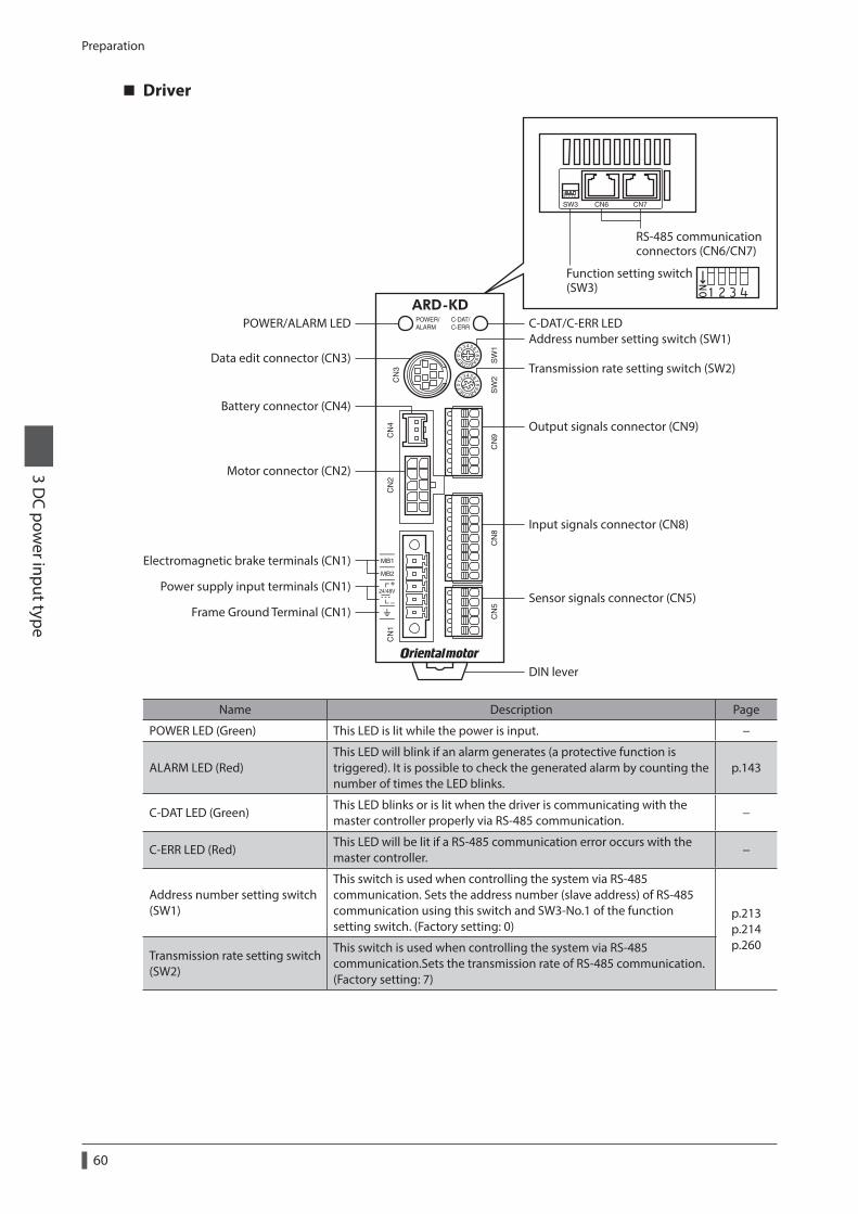
Preparation
3 DC pow
er input type
60
Driver
Transmission rate setting switch (SW2)
Address number setting switch (SW1)Data edit connector (CN3)
Motor connector (CN2)
Battery connector (CN4)
POWER/ALARM LED C-DAT/C-ERR LED
Output signals connector (CN9)
Input signals connector (CN8)
Sensor signals connector (CN5)Power supply input terminals (CN1)
Electromagnetic brake terminals (CN1)
Frame Ground Terminal (CN1)
DIN lever
Function setting switch(SW3)
RS-485 communication connectors (CN6/CN7)
Name Description Page
POWER LED (Green) This LED is lit while the power is input. −
ALARM LED (Red)This LED will blink if an alarm generates (a protective function is triggered). It is possible to check the generated alarm by counting the number of times the LED blinks.
p.143
C-DAT LED (Green)This LED blinks or is lit when the driver is communicating with the master controller properly via RS-485 communication.
−
C-ERR LED (Red)This LED will be lit if a RS-485 communication error occurs with the master controller.
−
Address number setting switch (SW1)
This switch is used when controlling the system via RS-485 communication. Sets the address number (slave address) of RS-485 communication using this switch and SW3-No.1 of the function setting switch. (Factory setting: 0)
p.213 p.214 p.260
Transmission rate setting switch (SW2)
This switch is used when controlling the system via RS-485 communication.Sets the transmission rate of RS-485 communication. (Factory setting: 7)
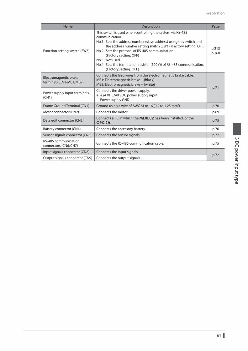
Preparation3 D
C power input type
61
Name Description Page
Function setting switch (SW3)
This switch is used when controlling the system via RS-485 communication. No.1: Sets the address number (slave address) using this switch and the address number setting switch (SW1). (Factory setting: OFF) No.2: Sets the protocol of RS-485 communication. (Factory setting: OFF) No.3: Not used. No.4: Sets the termination resistor (120 Ω) of RS-485 communication. (Factory setting: OFF)
p.213 p.260
Electromagnetic brake terminals (CN1-MB1/MB2)
Connects the lead wires from the electromagnetic brake cable. MB1: Electromagnetic brake − (black) MB2: Electromagnetic brake + (white)
p.71Power supply input terminals (CN1)
Connects the driver power supply. +: +24 VDC/48 VDC power supply input −: Power supply GND
Frame Ground Terminal (CN1) Ground using a wire of AWG24 to 16 (0.2 to 1.25 mm2). p.70
Motor connector (CN2) Connects the motor. p.69
Data edit connector (CN3)Connects a PC in which the MEXE02 has been installed, or the OPX-2A.
p.75
Battery connector (CN4) Connects the accessory battery. p.76
Sensor signals connector (CN5) Connects the sensor signals. p.72
RS-485 communication connectors (CN6/CN7)
Connects the RS-485 communication cable. p.75
Input signals connector (CN8) Connects the input signals.p.72
Output signals connector (CN9) Connects the output signals.

Installation
3 DC pow
er input type
62
3 Installation
This chapter explains the installation location and installation methods of the motor and driver, along with load installation.
3-1 Location for installation
The motor and driver are designed and manufactured to be incorporated in equipment. Install them in a well-ventilated location that provides easy access for inspection.The location must also satisfy the following conditions:
• Inside an enclosure that is installed indoors (provide vent holes) • Operating ambient temperature
Motor: −10 to +50 °C (+14 to +122 °F) (non-freezing) Harmonic geared type: 0 to +40 °C (+32 to +104 °F) (non-freezing) Driver: 0 to +50 °C (+32 to +122 °F) (non-freezing)
• Operating ambient humidity 85% or less (non-condensing) • Area that is free of explosive atmosphere or toxic gas (such as sulfuric gas) or liquid • Area not exposed to direct sun • Area free of excessive amount of dust, iron particles or the like • Area not subject to splashing water (rain, water droplets), oil (oil droplets) or other liquids • Area free of excessive salt • Area not subject to continuous vibration or excessive shocks • Area free of excessive electromagnetic noise (from welders, power machinery, etc.) • Area free of radioactive materials, magnetic fields or vacuum • 1,000 m (3,300 ft.) or lower above sea level
3-2 Installing the motor
The motor can be installed in any direction.To allow for heat dissipation and prevent vibration, install the motor on a metal surface of sufficient strength.
z Installation method A
Metal plate
Pilot-receiving hole
z Installation method B
Metal plate
Pilot-receiving hole
TypeFrame size [mm (in.)]
Screw size
Tightening torque [N·m (oz-in)]
Effective depth of screw thread [mm (in.)]
Installation method
Standard
20 (0.79) M2 0.25 (35) 2.5 (0.098)
A28 (1.10) M2.5 0.5 (71) 2.5 (0.098)
42 (1.65) M3 1 (142) 4.5 (0.177)
60 (2.36) M4 2 (280)− B
85 (3.35) M6 3 (420)
TH geared
28 (1.10) M2.5 0.5 (71) 4 (0.157)
A42 (1.65) 60 (2.36)
M4 2 (280) 8 (0.315)
90 (3.54) M8 4 (560) 15 (0.591)

Installation3 D
C power input type
63
TypeFrame size [mm (in.)]
Screw size
Tightening torque [N·m (oz-in)]
Effective depth of screw thread [mm (in.)]
Installation method
PS geared PN geared Harmonic geared *1
28 (1.10) 30 (1.18)
M3 1 (142) 6 (0.236)
A42 (1.65) M4 2 (280) 8 (0.315)
60 (2.36) M5 2.5 (350) 10 (0.394)
90 (3.54) M8 4 (560) 15 (0.591)
Harmonic geared *2 90 (3.54) M8 4 (560) − B
*1 ARM24, ARM46 and ARM66 type only.*2 ARM98 type only.
3-3 Installing a load
When connecting a load to the motor, align the centers of the motor output shaft and load shaft. Flexible couplings are available as accessories.
• When coupling the load to the motor, pay attention to the centering of the shafts, belt tension, parallelism of the pulleys, and so on. Securely tighten the coupling and pulley set screws.
• Be careful not to damage the output shaft or bearings when installing a coupling or pulley to the motor output shaft.
• Do not modify or machine the motor output shaft. Doing so may damage the bearings and destroy the motor.
• Do not apply strong force using hammer or other tools when removing the parallel key. Doing so may damage the motor output shaft and bearings (ball bearings).
z Using a couplingAlign the centers of the motor output shaft and load shaft in a straight line.
z Using a belt driveAlign the motor output shaft and load shaft in parallel with each other, and position both pulleys so that the line connecting their centers is at a right angle to the shafts.
z Using a gear driveAlign the motor output shaft and gear shaft in parallel with each other, and let the gears mesh at the center of the tooth widths.
• Using a coupling • Using a belt drive • Using a gear drive
z Using a parallel key (geared motor)When connecting the load and gear output shaft with a key slot, secure the load using the key included with the gear output shaft after machining the key slot on the load.

Installation
3 DC pow
er input type
64
z Harmonic geared type; Installing the load on the flange surface
With a Harmonic geared type (excluding ARM98), a load can be installed directly to the gear using the load mounting holes provided on the flange surface.
Flange surface
Load mounting holes
Motor modelScrew
sizeNumber of screw
Tightening torque
[N·m (oz-in)]
Effective depth of screw thread
[mm (in.)]
ARM24 M3 4 1.4 (198) 4 (0.157)
ARM46 M3 6 1.4 (198) 5 (0.197)
ARM66 M4 6 2.5 (350) 6 (0.236)
• When installing a load on the flange surface, the load cannot be mounted using the key slot in the output shaft.
• Design an appropriate installation layout so that the load will not contact the metal plate or screws used for installing the motor.
3-4 Permissible radial load and permissible axial load
• If the radial load or axial load exceeds the specified allowable value, repeated load applications may cause the bearing (ball bearings) or output shaft of the motor to undergo a fatigue failure.
• With a double shaft type, do not apply load torque, radial load or axial load to the output shaft on the opposite side of the motor output shaft.
The permissible radial load and permissible axial load of the PS geared type and PN geared type represent the value that the service life of the gear part satisfies 20,000 hours when either of the radial load or axial load is applied to the gear output shaft.
Type Motor model Gear ratio
Permissible radial load [N (lb.)]Permissible axial
load [N (lb.)]Distance from the tip of motor output shaft [mm (in.)]
0 (0) 5 (0.2) 10 (0.39) 15 (0.59) 20 (0.79)
Standard
ARM14 ARM15
−
12 (2.7) 15 (3.3) − − − 3 (0.67)
ARM24 ARM26
25 (5.6) 34 (7.6) 52 (11.7) − − 5 (1.12)
ARM46 35 (7.8) 44 (9.9) 58 (13) 85 (19.1) − 15 (3.3)
ARM66 ARM69
90 (20) 100 (22) 130 (29) 180 (40) 270 (60) 30 (6.7)
ARM98 260 (58) 290 (65) 340 (76) 390 (87) 480 (108) 60 (13.5)
TH geared
ARM24
All gear ratio
15 (3.3) 17 (3.8) 20 (4.5) 23 (5.1) − 10 (2.2)
ARM46 10 (2.2) 14 (3.1) 20 (4.5) 30 (6.7) − 15 (3.3)
ARM66 70 (15.7) 80 (18) 100 (22) 120 (27) 150 (33) 40 (9)
ARM98 220 (49) 250 (56) 300 (67) 350 (78) 400 (90) 100 (22)
PS geared
ARM24All gear
ratio45 (10.1) 60 (13.5) 80 (18) 100 (22) − 40 (9)
ARM46
5 70 (15.7) 80 (18) 95 (21) 120 (27) −
100 (22)
7.2 80 (18) 90 (20) 110 (24) 140 (31) −10 85 (19.1) 100 (22) 120 (27) 150 (33) −25 120 (27) 140 (31) 170 (38) 210 (47) −36 130 (29) 160 (36) 190 (42) 240 (54) −50 150 (33) 170 (38) 210 (47) 260 (58) −

Installation3 D
C power input type
65
Type Motor model Gear ratio
Permissible radial load [N (lb.)]Permissible axial
load [N (lb.)]Distance from the tip of motor output shaft [mm (in.)]
0 (0) 5 (0.2) 10 (0.39) 15 (0.59) 20 (0.79)
PS geared
ARM66
5 170 (38) 200 (45) 230 (51) 270 (60) 320 (72)
200 (45)
7.2 200 (45) 220 (49) 260 (58) 310 (69) 370 (83)
10 220 (49) 250 (56) 290 (65) 350 (78) 410 (92)
25 300 (67) 340 (76) 400 (90) 470 (105) 560 (126)
36 340 (76) 380 (85) 450 (101) 530 (119) 630 (141)
50 380 (85) 430 (96) 500 (112) 600 (135) 700 (157)
ARM98
5 380 (85) 420 (94) 470 (105) 540 (121) 630 (141)
600 (135)
7.2 430 (96) 470 (105) 530 (119) 610 (137) 710 (159)
10 480 (108) 530 (119) 590 (132) 680 (153) 790 (177)
25 650 (146) 720 (162) 810 (182) 920 (200) 1,070 (240)
36 730 (164) 810 (182) 910 (200) 1,040 (230) 1,210 (270)
50 820 (184) 910 (200) 1,020 (220) 1,160 (260) 1,350 (300)
PN geared
ARM24All gear
ratio45 (10.1) 60 (13.5) 80 (18) 100 (22) − 40 (9)
ARM46
5 80 (18) 95 (21) 120 (27) 160 (36) −100 (22)7.2 90 (20) 110 (24) 130 (29) 180 (40) −
10 100 (22) 120 (27) 150 (33) 200 (45) −
ARM66
5 240 (54) 260 (58) 280 (63) 300 (67) 330 (74)
200 (45)
7.2 270 (60) 290 (65) 310 (69) 340 (76) 370 (83)
10 300 (67) 320 (72) 350 (78) 380 (85) 410 (92)
25 410 (92) 440 (99) 470 (105) 520 (117) 560 (126)
36 360 (81) 410 (92) 480 (108) 570 (128) 640 (144)
50 360 (81) 410 (92) 480 (108) 570 (128) 700 (157)
ARM98
5 370 (83) 390 (87) 410 (92) 430 (96) 460 (103)
600 (135)
7.2 410 (92) 440 (99) 460 (103) 490 (110) 520 (117)
10 460 (103) 490 (110) 520 (117) 550 (123) 580 (130)
25 630 (141) 660 (148) 700 (157) 740 (166) 790 (177)
36 710 (159) 750 (168) 790 (177) 840 (189) 900 (200)
50 790 (177) 840 (189) 890 (200) 940 (210) 1,000 (220)
Harmonic geared
ARM24
All gear ratio
100 (22) 135 (30) 175 (39) 250 (56) − 140 (31)
ARM46 180 (40) 220 (49) 270 (60) 360 (81) 510 (114) 220 (49)
ARM66 320 (72) 370 (83) 440 (99) 550 (123) 720 (162) 450 (101)
ARM98 1,090 (240) 1,150 (250) 1,230 (270) 1,310 (290) 1,410 (310) 1,300 (290)
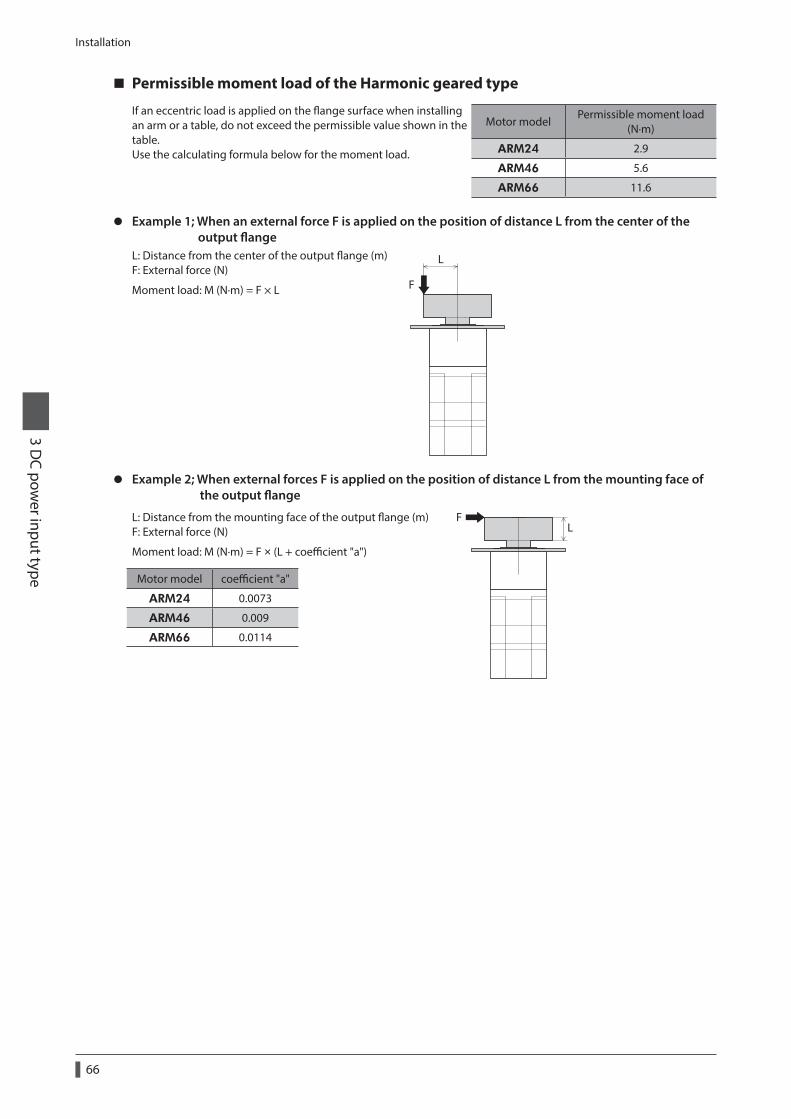
Installation
3 DC pow
er input type
66
Permissible moment load of the Harmonic geared type
If an eccentric load is applied on the flange surface when installing an arm or a table, do not exceed the permissible value shown in the table.Use the calculating formula below for the moment load.
Motor modelPermissible moment load
(N·m)
ARM24 2.9
ARM46 5.6
ARM66 11.6
z Example 1; When an external force F is applied on the position of distance L from the center of the output flangeL: Distance from the center of the output flange (m)F: External force (N)
Moment load: M (N·m) = F × L
L
F
z Example 2; When external forces F is applied on the position of distance L from the mounting face of the output flange
L: Distance from the mounting face of the output flange (m)F: External force (N)
Moment load: M (N·m) = F × (L + coefficient "a")
LF
Motor model coefficient "a"
ARM24 0.0073
ARM46 0.009
ARM66 0.0114

Installation3 D
C power input type
67
3-5 Installing the driver
Mount the driver to a 35 mm (1.38 in.) width DIN rail.When installing two or more drivers in parallel, it is possible to install them closely in the horizontal direction. Provide a minimum clearance of 50 mm (1.97 in.) in the vertical direction.When installing three or more drivers closely, the heat generation of the inside drivers become high. Install the less frequently used drivers toward the inside. Use the "Overheat warning" parameter to check the inside temperature of the driver.
35 (1.38)
50 (1.97) or more
100 (3.94)
Unit: mm (in.)
• Install the driver inside an enclosure whose pollution degree is 2 or better environment, or whose degree of protection is IP54 minimum.
• Do not install any equipment that generates a large amount of heat or noise near the driver.
• Do not install the driver underneath the controller or other equipment vulnerable to heat.
• If the ambient temperature of the driver exceeds 50 °C (122 °F), improve the ventilation condition.
• Be sure to install the driver vertically (vertical position).
1. Pull down the DIN lever of the driver and lock it. Hang the hook at the rear to the DIN rail.
2. Hold the driver to the DIN rail, and push up the DIN lever to secure.
3. Secure both sides of the driver using end plates.
Hook
DIN rail
DIN lever
End plateDIN lever
DIN rail
Removing from DIN railPull the DIN lever down until it locks using a slotted screwdriver, and lift the bottom of the driver to remove it from the rail. Use force of about 10 to 20 N (2.2 to 4.5 lb.) to pull the DIN lever to lock it. Excessive force may damage the DIN lever.

Installation
3 DC pow
er input type
68
Dimension [unit: mm (in.)]Mass: 0.17 kg (0.37 lb.)
[69 (2.72)] 70 (2.76)
4 (0.16)
35.1
(1.3
8)
17.5
(0.6
9)
13.4(0.53)
100
(3.9
4)
35 (1.38)
4.7
(0.1
9)
[41
(1.6
1)]
9.2
(0.3
6)
Slits
3-6 Installing the battery
A battery and battery holder are included in an accessory battery set BAT01B. Use the battery holder to secure the battery. See p.82 for accessory.
M4
13±0.3(0.51±0.012)
Battery holder
Battery Plate cutout for mounting [unit: mm (in.)]
Screws (M4)(not included)

Connection3 D
C power input type
69
4 Connection
This chapter explains how to connect the motor, I/O signals and power supply to the driver, as well as grounding method. The installation and wiring methods in compliance with the EMC Directive as well as protection against noise are also explained.
For protection against electric shock, do not turn on the power supply until the wiring is completed.
4-1 Connection example
The figure shows the electromagnetic brake type motor.
Cable for electromagnetic brake *2
Connect to CN1 *1
Connect to CN2 *1
Black
White
Cable for motor *2 *3
*4
Motor cable
*4
Output signalsConnect to CN9
Input signalsConnect to CN8
Sensor signalsConnect to CN5
Grounding
Grounding
DC power supply
Required
*1 Keep 30 m (98.4 ft.) or less for the wiring distance between the motor and driver.*2 Accessory. *3 Use the cable for motor when the length of the motor cable is not enough. *4 If connector covers are attached on cables, cover the connected connectors using them.
• Have the connector plugged in securely. Insecure connector connection may cause malfunction or damage to the motor or driver.
• When plugging/unplugging the connector, turn off the power and wait for the POWER LED to turn off.
• When connecting, check the silk screen of the driver and pay attention to the polarity of the power supply. Reverse-polarity connection may cause damage to the driver. The power-supply circuit and the RS-485 communication circuit are not insulated. Therefore, when controlling multiple drivers via RS-485 communication, the reverse polarity of the power supply will cause a short circuit and may result in damage to the drivers.
• Do not wire the power supply cable of the driver in the same cable duct with other power lines or motor cables. Doing so may cause malfunction due to noise.
• The lead wires of the "cable for electromagnetic brake" have polarities, so connect them in the correct polarities. If the lead wires are connected with their polarities reversed, the electromagnetic brake will not operate properly.
• When unplugging the connector, do so while pressing the latches on the connector. • When installing the motor on a moving part, use a flexible cable having excellent flex resistance. Refer to p.79 for details.

Connection
3 DC pow
er input type
70
z Cable size and tightening torque
ConnectorTerminal symbol
Recommended cable size Screw sizeTightening torque
[N·m (oz-in)]
CN124/48V+ 24/48V−
Stranded wire AWG24 to 16 (0.2 to 1.25 mm2)M2
0.22 to 0.25 (31 to 35)
MB1, MB2 Stranded wire AWG20 (0.5 mm2)
CN5 − Stranded wire AWG26 to 20 (0.14 to 0.5 mm2) − −
CN8 − Stranded wire AWG26 to 20 (0.14 to 0.5 mm2) − −
CN9 − Stranded wire AWG26 to 20 (0.14 to 0.5 mm2) − −
4-2 Grounding the motor and driver
Grounding the motorBe sure to ground the Protective Earth Terminal of the motor. (It is no need to ground when the driver power supply voltage is 24 VDC.)
• Grounding wire: AWG18 (0.75 mm2) or more • Screw size: M4 • Tightening torque: 1.2 N·m (170 oz-in)
Use a round terminal when grounding, and secure it with a mounting screw with a washer. Ground wires and crimp terminals are not included.
Grounding
Protective Earth Terminal
Grounding the driverGround the Frame Ground Terminal (CN1) as necessary.Use a grounding wire of AWG24 to 16 (0.2 to 1.25 mm2), and do not share the Frame Ground Terminal with a welder or any other power equipment.
+24/48 VDC Connect to CN1
GND
Grounding

Connection3 D
C power input type
71
4-3 Connecting the power supply and electromagnetic brake
Use the CN1 connector (5 pins) to connect the power supply and electromagnetic brake
Connecting method
1. Strip the insulation cover of the lead wire (AWG24 to 16: 0.2 to 1.25 mm2) by 7 mm (0.28 in.)
2. Insert each lead wire into the CN1 connector and tighten the screw with a slotted screwdriver.Connector screw size: M2Tightening torque: 0.22 to 0.25 N·m (31 to 35 oz-in)
3. Insert the CN1 connector into the CN1, and tighten the screw.Connector screw size: M2.5Tightening torque: 0.4 N·m (56 oz-in)
7 mm(0.28 in.)
Lead wires
CN1 connector
CN1
Slotted screwdriver
Pin assignment
Pin No. Signal name Description
1
5
···
1 MB1 Electromagnetic brake − (Black)
2 MB2 Electromagnetic brake + (White)
3 + 24 VDC/48 VDC power supply input
4 − Power supply ground
5 FG Frame ground
Power supply current capacity
Motor modelInput power
supply voltagePower supply current capacity
Without electromagnetic brake With electromagnetic brake
ARM14
24 VDC±5% *
0.4 A or more −
ARM15 0.5 A or more −
ARM24 ARM26
1.25 A or more 1.3 A or more
ARM46
24 VDC±5% * 48 VDC±5%
1.72 A or more 1.8 A or more
ARM66 3.55 A or more 3.8 A or more
ARM69 3.45 A or more 3.7 A or more
ARM98 2.85 A or more 3.1 A or more
* If the distance between the motor and driver is extended to 20 to 30 m (65.6 to 98.4 ft.), use a power supply of 24 VDC±4%.

Connection
3 DC pow
er input type
72
4-4 Connecting the I/O signals
Wiring method • Applicable lead wire: AWG26 to 20 (0.14 to 0.5 mm2) • Stripping length of wire insulation: 8 mm (0.31 in.)
1. Strip the insulation cover of the lead wire.
2. Insert the lead wire while pushing the button of the orange color on the connector with a slotted screwdriver.
3. After having inserted, release the button to secure the lead wire.
Button of the orange color
Lead wire
Pin assignment
z Sensor signals (CN5)
Pin No. Signal name Description
1
5
···
1 +LS Limit sensor input +
2 −LS Limit sensor input −
3 HOMES Mechanical home sensor input
4 SLIT Slit sensor input
5 IN-COM2 Sensor signals common
z Input signals (CN8)
Pin No. Signal name Description *
1
9
·····
1 IN0 Control input 0 (HOME)
2 IN1 Control input 1 (START)
3 IN2 Control input 2 (M0)
4 IN3 Control input 3 (M1)
5 IN4 Control input 4 (M2)
6 IN5 Control input 5 (FREE)
7 IN6 Control input 6 (STOP)
8 IN7 Control input 7 (ALM-RST)
9 IN-COM1 Input signals common
* ( ): Initial value
z Output signals (CN9)
Pin No. Signal name Description *
1
7
····
1 OUT0 Control output 0 (HOME-P)
2 OUT1 Control output 1 (END)
3 OUT2 Control output 2 (AREA1)
4 OUT3 Control output 3 (READY)
5 OUT4 Control output 4 (WNG)
6 OUT5 Control output 5 (ALM)
7 OUT-COM Output signals common
* ( ): Initial value

Connection3 D
C power input type
73
Connection example with a current sink output circuit (NPN specifications)
1
2
3
4
5
6
7
1
2
3
4
5
6
7
8
9
1
2
3
4
5
DriverController
24 VDC
12 to 24 VDC
Output saturated voltage3 V max.
OUT0 (HOME-P)CN9
IN0 (HOME)
IN1 (START)
IN2 (M0)
IN3 (M1)
IN4 (M2)
IN-COM1
IN7 (ALM-RST)
IN6 (STOP)
IN5 (FREE)
CN8
+LS
( ): Initial value
-LS
HOMES
SLIT
IN-COM2
CN5
OUT1 (END)
OUT2 (AREA1)
OUT3 (READY)
OUT4 (WNG)
OUT5 (ALM)
OUT-COM
4.4 kΩ
4.4 kΩ1 kΩ
1 kΩ
1 kΩ
1 kΩ
1 kΩ
1 kΩ
1 kΩ
1 kΩ
4.4 kΩ
4.4 kΩ
4.4 kΩ
4.4 kΩ
4.4 kΩ
4.4 kΩ
1 kΩ
1 kΩ
1 kΩ
1 kΩ
4.4 kΩ
4.4 kΩ
4.4 kΩ
4.4 kΩ
R0
R0
R0
R0
R0
R0
24 VDC
0 V
0 V
0 V
NPN sensor
10 mA or less
• Use input signals at 24 VDC. • Use output signals at 12 to 24 VDC 10 mA or less. If the current exceeds 10 mA, connect an external resistor R0 so that the current becomes 10 mA or less.
• The saturated voltage of the output signal is 3 VDC maximum.

Connection
3 DC pow
er input type
74
Connection example with a current source output circuit (PNP specifications)
1
2
3
4
5
6
7
89
1
2
3
4
5
6
7
1
2
3
4
5
Controller
24 VDC
12 to 24 VDC
Output saturated voltage3 V max.
CN9
CN8
CN5
4.4 kΩ
4.4 kΩ1 kΩ
1 kΩ
1 kΩ
1 kΩ
1 kΩ
1 kΩ
1 kΩ
1 kΩ
4.4 kΩ
4.4 kΩ
4.4 kΩ
4.4 kΩ
4.4 kΩ
4.4 kΩ
1 kΩ
1 kΩ
1 kΩ
1 kΩ
4.4 kΩ
4.4 kΩ
4.4 kΩ
4.4 kΩ
R0
R0
R0
R0
R0
R0
24 VDC
0 V
0 V
0 V
PNP sensor
OUT0 (HOME-P)
IN0 (HOME)
IN1 (START)
IN2 (M0)
IN3 (M1)
IN4 (M2)
IN-COM1IN7 (ALM-RST)
IN6 (STOP)
IN5 (FREE)
+LS
( ): Initial value
-LS
HOMES
SLIT
IN-COM2
OUT1 (END)
OUT2 (AREA1)
OUT3 (READY)
OUT4 (WNG)
OUT5 (ALM)
OUT-COM
10 mA or less
Driver
• Use input signals at 24 VDC. • Use output signals at 12 to 24 VDC 10 mA or less. If the current exceeds 10 mA, connect an external resistor R0 so that the current becomes 10 mA or less.
• The saturated voltage of the output signal is 3 VDC maximum.

Connection3 D
C power input type
75
4-5 Connecting the data setter
Connect the communication cable for the support software or OPX-2A cable to the data edit connector (CN3) on the driver.
Communication cable for the support software or OPX-2A cable
Connect to CN3
The power supply connector (CN1), data edit connector (CN3), and RS-485 communication connectors (CN6/CN7) of the driver are not insulated. When grounding the positive terminal of the power supply, do not connect any equipment (PC, etc.) whose negative terminal is grounded. Doing so may cause the driver and these equipment to short, damaging both.
4-6 Connecting the RS-485 communication cable
Connect this cable if you want to control your product via RS-485 communication. Connect the RS-485 communication cable to CN6 or CN7 on the driver.You can use the vacant connectors to connect a different driver. A driver link cable is available as an accessory. See p.82. You can also use a commercial LAN cable (straight cable) to link drivers.
RS-485 communicationconnectors (CN6/CN7)
Drivers can be linked.
Function setting switch(SW3)
• Internal input circuit
1 N.C.2 GND3 TR+4 N.C.5 N.C.6 TR-7 N.C.8 N.C.
1 N.C.2 GND3 TR+4 N.C.5 N.C.6 TR-7 N.C.8 N.C.
120 Ω
0 V *
SW3-No.4
* The GND line is used in common with CN1 (not insulated).
CN6/CN7 pin assignment
Pin No. Signal name Description
1
8
···
1 N.C. Not used.
2 GND GND
3 TR+ RS-485 communication signal (+)
4 N.C.Not used.
5 N.C.
6 TR− RS-485 communication signal (−)
7 N.C.Not used.
8 N.C.
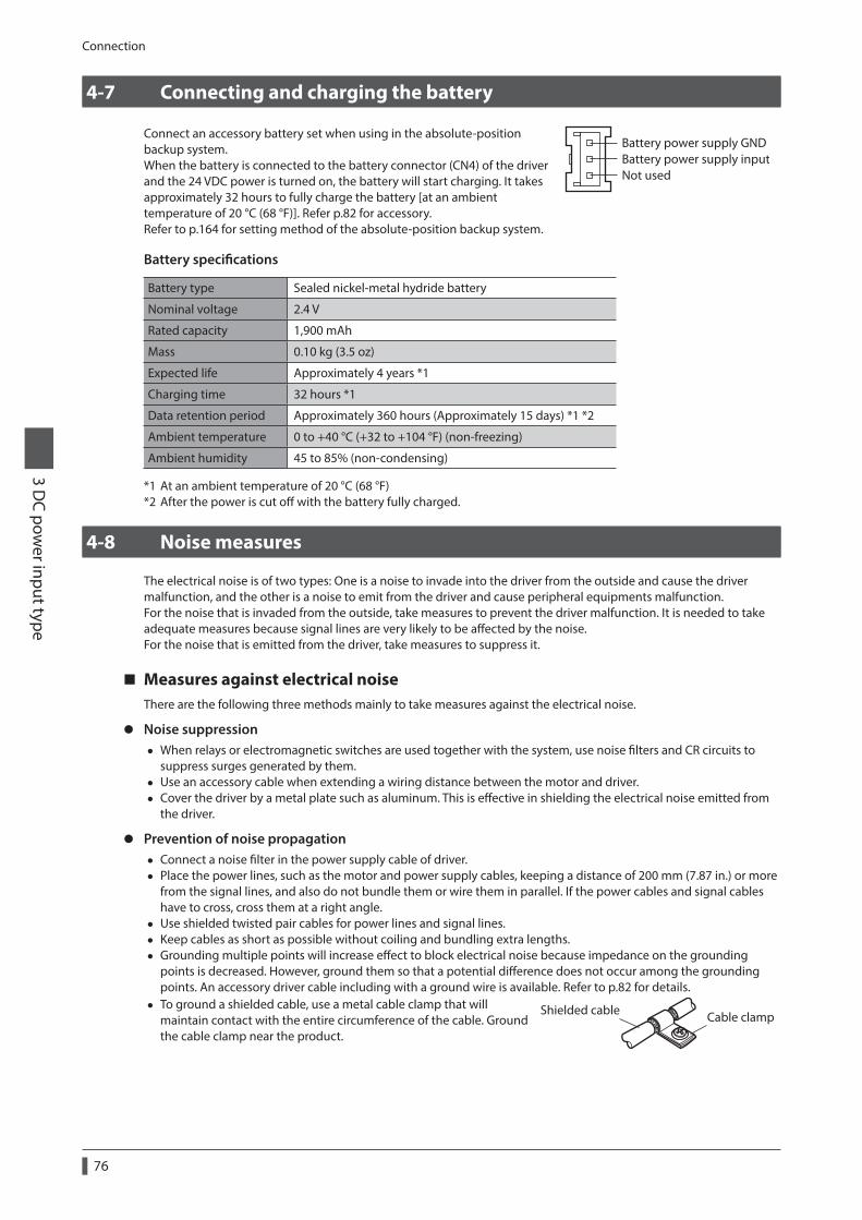
Connection
3 DC pow
er input type
76
4-7 Connecting and charging the battery
Connect an accessory battery set when using in the absolute-position backup system.When the battery is connected to the battery connector (CN4) of the driver and the 24 VDC power is turned on, the battery will start charging. It takes approximately 32 hours to fully charge the battery [at an ambient temperature of 20 °C (68 °F)]. Refer p.82 for accessory.Refer to p.164 for setting method of the absolute-position backup system.
Battery power supply GNDBattery power supply inputNot used
Battery specifications
Battery type Sealed nickel-metal hydride battery
Nominal voltage 2.4 V
Rated capacity 1,900 mAh
Mass 0.10 kg (3.5 oz)
Expected life Approximately 4 years *1
Charging time 32 hours *1
Data retention period Approximately 360 hours (Approximately 15 days) *1 *2
Ambient temperature 0 to +40 °C (+32 to +104 °F) (non-freezing)
Ambient humidity 45 to 85% (non-condensing)
*1 At an ambient temperature of 20 °C (68 °F)*2 After the power is cut off with the battery fully charged.
4-8 Noise measures
The electrical noise is of two types: One is a noise to invade into the driver from the outside and cause the driver malfunction, and the other is a noise to emit from the driver and cause peripheral equipments malfunction.For the noise that is invaded from the outside, take measures to prevent the driver malfunction. It is needed to take adequate measures because signal lines are very likely to be affected by the noise.For the noise that is emitted from the driver, take measures to suppress it.
Measures against electrical noiseThere are the following three methods mainly to take measures against the electrical noise.
z Noise suppression • When relays or electromagnetic switches are used together with the system, use noise filters and CR circuits to
suppress surges generated by them. • Use an accessory cable when extending a wiring distance between the motor and driver. • Cover the driver by a metal plate such as aluminum. This is effective in shielding the electrical noise emitted from
the driver.
z Prevention of noise propagation • Connect a noise filter in the power supply cable of driver. • Place the power lines, such as the motor and power supply cables, keeping a distance of 200 mm (7.87 in.) or more
from the signal lines, and also do not bundle them or wire them in parallel. If the power cables and signal cables have to cross, cross them at a right angle.
• Use shielded twisted pair cables for power lines and signal lines. • Keep cables as short as possible without coiling and bundling extra lengths. • Grounding multiple points will increase effect to block electrical noise because impedance on the grounding
points is decreased. However, ground them so that a potential difference does not occur among the grounding points. An accessory driver cable including with a ground wire is available. Refer to p.82 for details.
• To ground a shielded cable, use a metal cable clamp that will maintain contact with the entire circumference of the cable. Ground the cable clamp near the product.
Cable clampShielded cable
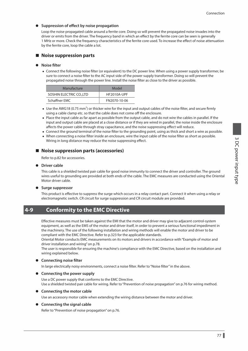
Connection3 D
C power input type
77
z Suppression of effect by noise propagationLoop the noise propagated cable around a ferrite core. Doing so will prevent the propagated noise invades into the driver or emits from the driver. The frequency band in which an effect by the ferrite core can be seen is generally 1 MHz or more. Check the frequency characteristics of the ferrite core used. To increase the effect of noise attenuation by the ferrite core, loop the cable a lot.
Noise suppression parts
z Noise filter • Connect the following noise filter (or equivalent) to the DC power line. When using a power supply transformer, be
sure to connect a noise filter to the AC input side of the power supply transformer. Doing so will prevent the propagated noise through the power line. Install the noise filter as close to the driver as possible.
Manufacture Model
SOSHIN ELECTRIC CO.,LTD HF2010A-UPF
Schaffner EMC FN2070-10-06
• Use the AWG18 (0.75 mm2) or thicker wire for the input and output cables of the noise filter, and secure firmly using a cable clamp etc. so that the cable does not come off the enclosure.
• Place the input cable as far apart as possible from the output cable, and do not wire the cables in parallel. If the input and output cable are placed at a close distance or if they are wired in parallel, the noise inside the enclosure affects the power cable through stray capacitance, and the noise suppressing effect will reduce.
• Connect the ground terminal of the noise filter to the grounding point, using as thick and short a wire as possible. • When connecting a noise filter inside an enclosure, wire the input cable of the noise filter as short as possible.
Wiring in long distance may reduce the noise suppressing effect.
Noise suppression parts (accessories)Refer to p.82 for accessories.
z Driver cableThis cable is a shielded twisted pair cable for good noise immunity to connect the driver and controller. The ground wires useful to grounding are provided at both ends of the cable. The EMC measures are conducted using the Oriental Motor driver cable.
z Surge suppressorThis product is effective to suppress the surge which occurs in a relay contact part. Connect it when using a relay or electromagnetic switch. CR circuit for surge suppression and CR circuit module are provided.
4-9 Conformity to the EMC Directive
Effective measures must be taken against the EMI that the motor and driver may give to adjacent control-system equipment, as well as the EMS of the motor and driver itself, in order to prevent a serious functional impediment in the machinery. The use of the following installation and wiring methods will enable the motor and driver to be compliant with the EMC Directive. Refer to p.323 for the applicable standards.Oriental Motor conducts EMC measurements on its motors and drivers in accordance with “Example of motor and driver installation and wiring” on p.78.The user is responsible for ensuring the machine's compliance with the EMC Directive, based on the installation and wiring explained below.
z Connecting noise filterIn large electrically noisy environments, connect a noise filter. Refer to “Noise filter” in the above.
z Connecting the power supplyUse a DC power supply that conforms to the EMC Directive.Use a shielded twisted pair cable for wiring. Refer to “Prevention of noise propagation” on p.76 for wiring method.
z Connecting the motor cableUse an accessory motor cable when extending the wiring distance between the motor and driver.
z Connecting the signal cableRefer to “Prevention of noise propagation” on p.76.

Connection
3 DC pow
er input type
78
z How to ground • The cable used to ground the motor, driver and noise filter must be as thick and short as possible so that no
potential difference is generated. • Choose a large, thick and uniformly conductive surface for the grounding point. • Be sure to ground the Protective Earth Terminal of the motor and driver. Refer to p.70 for grounding method.
z Example of motor and driver installation and wiring
Grounding
Grounding
Grounding
Grounding
GroundingGrounding
Grounding
Motor
Controller
Driver
Sensor
Shielded cable
Shielded cableMotor cable
(shielded cable)
Shielded cable
RS-485 communication cable
Grounded panel
OPX-2A
BAT01B
Cableclamp
Cableclamp
Noise lterDC power
supplyAC
The driver uses parts that are sensitive to electrostatic charge. Take measures against static electricity since static electricity may cause the driver to malfunction or suffer damage.

Accessories3 D
C power input type
79
5 Accessories
5-1 Motor cable set
When installing the motor on a moving part, use a flexible cable having excellent flex resistance.
Connection cable setUse when connecting a motor and a driver. The cable set for electromagnetic brake motors consists of two cables, one for motor and the other for electromagnetic brake.
*1 Only when the motor is of electromagnetic brake type.*2 A connector cover may be attached depending on the specication.
For motor
For electormagnetic brake *1
Connection cable
*2
*2
*2
*2
z Connection cable set model
Length [m (ft.)]
For standard type motor For electromagnetic brake type motor
Without connector cover With connector cover Without connector cover With connector cover
0.5 (1.6) CC005VA2F2 − CC005VA2FB2 −
1 (3.3) CC010VA2F2 CC010VAF2 CC010VA2FB2 CC010VAFB2
1.5 (4.9) CC015VA2F2 − CC015VA2FB2 −
2 (6.6) CC020VA2F2 CC020VAF2 CC020VA2FB2 CC020VAFB2
2.5 (8.2) CC025VA2F2 − CC025VA2FB2 −
3 (9.8) CC030VA2F2 CC030VAF2 CC030VA2FB2 CC030VAFB2
4 (13.1) CC040VA2F2 − CC040VA2FB2 −
5 (16.4) CC050VA2F2 CC050VAF2 CC050VA2FB2 CC050VAFB2
7 (23) CC070VA2F2 CC070VAF2 CC070VA2FB2 CC070VAFB2
10 (32.8) CC100VA2F2 CC100VAF2 CC100VA2FB2 CC100VAFB2
15 (49.2) CC150VA2F2 CC150VAF2 CC150VA2FB2 CC150VAFB2
20 (65.6) CC200VA2F2 CC200VAF2 CC200VA2FB2 CC200VAFB2
30 (98.4) CC300VA2F2 CC300VAF2 CC300VA2FB2 CC300VAFB2

Accessories
3 DC pow
er input type
80
z Flexible connection cable set model
Length [m (ft.)]
For standard type motor For electromagnetic brake type motor
Without connector cover With connector cover Without connector cover With connector cover
0.5 (1.6) CC005VA2R2 − CC005VA2RB2 −
1 (3.3) CC010VA2R2 CC010VAR2 CC010VA2RB2 CC010VARB2
1.5 (4.9) CC015VA2R2 − CC015VA2RB2 −
2 (6.6) CC020VA2R2 CC020VAR2 CC020VA2RB2 CC020VARB2
2.5 (8.2) CC025VA2R2 − CC025VA2RB2 −
3 (9.8) CC030VA2R2 CC030VAR2 CC030VA2RB2 CC030VARB2
4 (13.1) CC040VA2R2 − CC040VA2RB2 −
5 (16.4) CC050VA2R2 CC050VAR2 CC050VA2RB2 CC050VARB2
7 (23) CC070VA2R2 CC070VAR2 CC070VA2RB2 CC070VARB2
10 (32.8) CC100VA2R2 CC100VAR2 CC100VA2RB2 CC100VARB2
15 (49.2) CC150VA2R2 CC150VAR2 CC150VA2RB2 CC150VARB2
20 (65.6) CC200VA2R2 CC200VAR2 CC200VA2RB2 CC200VARB2
30 (98.4) CC300VA2R2 CC300VAR2 CC300VA2RB2 CC300VARB2
Extension cable setUse when extending the distance between a motor and a driver or when the length of the connection cable used is not enough. Extend the distance by connecting the extension cable to the connection cable.The cable set for electromagnetic brake motors consists of two cables, one for motor and the other for electromagnetic brake.
*1 Use the connection cable used.*2 Only when the motor is of electromagnetic brake type.*3 A connector cover may be attached depending on the specication.
For motor
For electromagnetic brake *2
Extension cable Connection cable *1
For motor
For electromagnetic brake *2
*3
*3
*3
*3
*3
*3
*3
*3
When extending the wiring length by connecting an extension cable to the connection cable, keep the total cable length to 30 m (98.4 ft.) or less.

Accessories3 D
C power input type
81
z Extension cable set model
Length [m (ft.)]
For standard type motor For electromagnetic brake type motor
Without connector cover With connector cover Without connector cover With connector cover
0.5 (1.6) CC005VA2F2 − CC005VA2FBT2 −
1 (3.3) CC010VA2F2 CC010VAFT2 CC010VA2FBT2 CC010VAFBT2
1.5 (4.9) CC015VA2F2 − CC015VA2FBT2 −
2 (6.6) CC020VA2F2 CC020VAFT2 CC020VA2FBT2 CC020VAFBT2
2.5 (8.2) CC025VA2F2 − CC025VA2FBT2 −
3 (9.8) CC030VA2F2 CC030VAFT2 CC030VA2FBT2 CC030VAFBT2
4 (13.1) CC040VA2F2 − CC040VA2FBT2 −
5 (16.4) CC050VA2F2 CC050VAFT2 CC050VA2FBT2 CC050VAFBT2
7 (23) CC070VA2F2 CC070VAFT2 CC070VA2FBT2 CC070VAFBT2
10 (32.8) CC100VA2F2 CC100VAFT2 CC100VA2FBT2 CC100VAFBT2
15 (49.2) CC150VA2F2 CC150VAFT2 CC150VA2FBT2 CC150VAFBT2
20 (65.6) CC200VA2F2 CC200VAFT2 CC200VA2FBT2 CC200VAFBT2
z Flexible extension cable set model
Length [m (ft.)]
For standard type motor For electromagnetic brake type motor
Without connector cover With connector cover Without connector cover With connector cover
0.5 (1.6) CC005VA2R2 − CC005VA2RBT2 −
1 (3.3) CC010VA2R2 CC010VART2 CC010VA2RBT2 CC010VARBT2
1.5 (4.9) CC015VA2R2 − CC015VA2RBT2 −
2 (6.6) CC020VA2R2 CC020VART2 CC020VA2RBT2 CC020VARBT2
2.5 (8.2) CC025VA2R2 − CC025VA2RBT2 −
3 (9.8) CC030VA2R2 CC030VART2 CC030VA2RBT2 CC030VARBT2
4 (13.1) CC040VA2R2 − CC040VA2RBT2 −
5 (16.4) CC050VA2R2 CC050VART2 CC050VA2RBT2 CC050VARBT2
7 (23) CC070VA2R2 CC070VART2 CC070VA2RBT2 CC070VARBT2
10 (32.8) CC100VA2R2 CC100VART2 CC100VA2RBT2 CC100VARBT2
15 (49.2) CC150VA2R2 CC150VART2 CC150VA2RBT2 CC150VARBT2
20 (65.6) CC200VA2R2 CC200VART2 CC200VA2RBT2 CC200VARBT2
5-2 Setting tool
Communication cable for the support softwareBe sure to purchase the communication cable for the support software when connecting a driver and PC in which the support software MEXE02 has been installed.This is a set of a PC interface cable and USB cable. The cable is connected to the USB port on the PC.
Model: CC05IF-USB [5 m (16.4 ft.)]
The MEXE02 can be downloaded from Oriental Motor Website Download Page. Also, the MEXE02 is provided in the form of a storage medium. For details, check out our web site or contact your nearest Oriental Motor sales office.
Data setterThe data setter lets you set operation data and parameters for your AR Series with ease and also functions as a monitor.
Model: OPX-2A

Accessories
3 DC pow
er input type
82
5-3 Wiring support tool
RS-485 communication cableYou can link drivers using this cable connected to the RS-485 communication connectors (CN6, CN7).
Model: CC001-RS4 [0.1 m (0.3 ft.)] CC002-RS4 [0.25 m (0.8 ft.)]
Driver cableA shielded cable for driver control I/O signals offering excellent noise resistance. The ground wires useful to grounding are provided at both ends of the cable.Select the cable suitable for the number of I/O signals connected.
Driver cable model list
Cable length [m (ft.)]
Number of lead wire
6 pcs. 10 pcs. 12 pcs. 16 pcs.
0.5 (1.6) CC06D005B-1 CC10D005B-1 CC12D005B-1 CC16D005B-1
1 (3.3) CC06D010B-1 CC10D010B-1 CC12D010B-1 CC16D010B-1
1.5 (4.9) CC06D015B-1 CC10D015B-1 CC12D015B-1 CC16D015B-1
2 (6.6) CC06D020B-1 CC10D020B-1 CC12D020B-1 CC16D020B-1
CR circuit for surge suppressionThis product is effective to suppress the serge which occurs in a relay contact part. Use it to protect the contacts of the relay or switch.
Model: EPCR1201-2
CR circuit moduleThis product is effective to suppress the surge which occurs in a relay contact part. Use this product to protect the contacts of the relay or switch.Four pieces of CR circuit for surge suppression are mounted on the compact circuit, and this product can be installed to the DIN rail. This product can make the wiring easily and securely since it also supports terminal block connection.
Model: VCS02
5-4 Others
Battery setThis is a battery set (including a battery and battery holder) required in the absolute-position backup system.
Model: BAT01B

4 AC power input type/ DC power input type Common
This part explains common contents to the AR Series AC power input type and DC power input type.
Table of contents
1 Explanation of I/O signals .................... 841-1 Assignment of direct I/O .............................. 841-2 Assignment of remote I/O ........................... 881-3 Input signals ..................................................... 921-4 Output signals ................................................. 981-5 Sensor inputs .................................................1031-6 General signals (R0 to R15) ........................104
2 Method of control via I/O ...................1052-1 Guidance ..........................................................1052-2 Operation data ..............................................1092-3 Parameter ........................................................110
3 Operation using the OPX-2A ...........1213-1 Overview of the OPX-2A ..........................1213-2 Names and functions of parts ..................1223-3 How to read the display .............................1223-4 OPX-2A error display .................................1233-5 Screen transitions .........................................124
3-6 Monitor mode ................................................1283-7 Data mode .......................................................1293-8 Parameter mode ...........................................1323-9 Test mode ........................................................1393-10 Copy mode ......................................................141
4 Inspection and maintenance ............1424-1 Inspection ........................................................1424-2 Warranty ...........................................................1424-3 Disposal ............................................................142
5 Alarms and warnings ..........................1435-1 Alarms ...............................................................1435-2 Warning ............................................................1505-3 Communication errors ................................151
6 Troubleshooting and remedial actions ..................................152
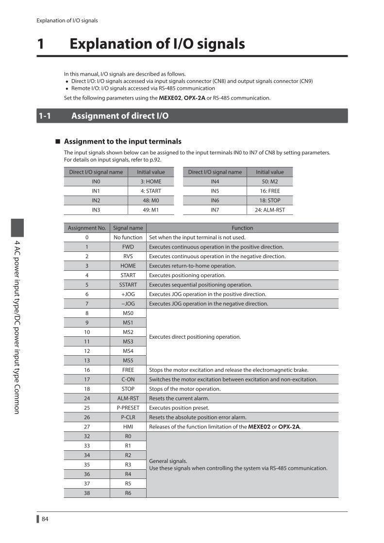
Explanation of I/O signals
4 AC power input type/D
C power input type Com
mon
84
1 Explanation of I/O signals
In this manual, I/O signals are described as follows. • Direct I/O: I/O signals accessed via input signals connector (CN8) and output signals connector (CN9) • Remote I/O: I/O signals accessed via RS-485 communication
Set the following parameters using the MEXE02, OPX-2A or RS-485 communication.
1-1 Assignment of direct I/O
Assignment to the input terminalsThe input signals shown below can be assigned to the input terminals IN0 to IN7 of CN8 by setting parameters.For details on input signals, refer to p.92.
Direct I/O signal name Initial value Direct I/O signal name Initial value
IN0 3: HOME IN4 50: M2
IN1 4: START IN5 16: FREE
IN2 48: M0 IN6 18: STOP
IN3 49: M1 IN7 24: ALM-RST
Assignment No. Signal name Function
0 No function Set when the input terminal is not used.
1 FWD Executes continuous operation in the positive direction.
2 RVS Executes continuous operation in the negative direction.
3 HOME Executes return-to-home operation.
4 START Executes positioning operation.
5 SSTART Executes sequential positioning operation.
6 +JOG Executes JOG operation in the positive direction.
7 −JOG Executes JOG operation in the negative direction.
8 MS0
Executes direct positioning operation.
9 MS1
10 MS2
11 MS3
12 MS4
13 MS5
16 FREE Stops the motor excitation and release the electromagnetic brake.
17 C-ON Switches the motor excitation between excitation and non-excitation.
18 STOP Stops of the motor operation.
24 ALM-RST Resets the current alarm.
25 P-PRESET Executes position preset.
26 P-CLR Resets the absolute position error alarm.
27 HMI Releases of the function limitation of the MEXE02 or OPX-2A.
32 R0
General signals. Use these signals when controlling the system via RS-485 communication.
33 R1
34 R2
35 R3
36 R4
37 R5
38 R6

Explanation of I/O signals4 AC pow
er input type/DC pow
er input type Comm
on
85
Assignment No. Signal name Function
39 R7
General signals. Use these signals when controlling the system via RS-485 communication.
40 R8
41 R9
42 R10
43 R11
44 R12
45 R13
46 R14
47 R15
48 M0
Selects the operation data No. using these six bits.
49 M1
50 M2
51 M3
52 M4
53 M5
Related parameter
MEXE02 tree view Parameter name Description Initial value
I/O function [Input]
IN0 input function selection
Assigns the following input signals to IN0 to IN7 of the input terminals.
[Setting range] Refer to the table next.
3: HOME
IN1 input function selection 4: START
IN2 input function selection 48: M0
IN3 input function selection 49: M1
IN4 input function selection 50: M2
IN5 input function selection 16: FREE
IN6 input function selection 18: STOP
IN7 input function selection 24: ALM-RST
0: No function 1: FWD 2: RVS 3: HOME 4: START 5: SSTART 6: +JOG 7: −JOG
8: MS0 9: MS1 10: MS2 11: MS3 12: MS4 13: MS5 16: FREE 17: C-ON
18: STOP 24: ALM-RST 25: P-PRESET 26: P-CLR 27: HMI 32: R0 33: R1 34: R2
35: R3 36: R4 37: R5 38: R6 39: R7 40: R8 41: R9 42: R10
43: R11 44: R12 45: R13 46: R14 47: R15 48: M0 49: M1 50: M2
51: M3 52: M4 53: M5
• Do not assign the same input signal to multiple input terminals. When the same input signal is assigned to multiple input terminals, the function will be executed if any of the terminals becomes active.
• The ALM-RST input and P-CLR input will be executed when turning from ON to OFF. The P-PRESET input will be executed when turning from OFF to ON.
• When the C-ON input and HMI input are not assigned to the input terminals, these inputs will always be set to ON. When assigning to both direct I/O and remote I/O, the function will be executed when both of them are set to ON.

Explanation of I/O signals
4 AC power input type/D
C power input type Com
mon
86
Changing the logic level setting of input signalsYou can change the logic level setting for input terminals IN0 to IN7 using the parameter.
Related parameter
MEXE02 tree view Parameter name Description Initial value
I/O function [Input]
IN0 input logic level setting
Changes the logic level setting for input terminals IN0 to IN7.
[Setting range] 0: Make (N.O.) 1: Brake (N.C.)
0
IN1 input logic level setting
IN2 input logic level setting
IN3 input logic level setting
IN4 input logic level setting
IN5 input logic level setting
IN6 input logic level setting
IN7 input logic level setting
Assignment to the output terminalsThe output signals shown below can be assigned to the output terminals OUT0 to OUT5 of CN9 by setting parameters. For details on output signals, refer to p.98.
Direct I/O signal name Initial value Direct I/O signal name Initial value
OUT0 70: HOME-P OUT3 67: READY
OUT1 69: END OUT4 66: WNG
OUT2 73: AREA1 OUT5 65: ALM
Assignment No. Signal name Function
0 No function Sets when the output terminal is not used.
1 FWD_R Outputs in response to the FWD input.
2 RVS_R Outputs in response to the RVS input.
3 HOME_R Outputs in response to the HOME input.
4 START_R Outputs in response to the START input.
5 SSTART_R Outputs in response to the SSTART input.
6 +JOG_R Outputs in response to the +JOG input.
7 −JOG_R Outputs in response to the −JOG input.
8 MS0_R
Outputs in response to the MS0 to MS5 input.
9 MS1_R
10 MS2_R
11 MS3_R
12 MS4_R
13 MS5_R
16 FREE_R Outputs in response to the FREE input.
17 C-ON_R Outputs in response to the C-ON input.
18 STOP_R Outputs in response to the STOP input.
32 R0
Outputs the status of the general signal R0 to R9.
33 R1
34 R2
35 R3
36 R4
37 R5
38 R6
39 R7
40 R8
41 R9
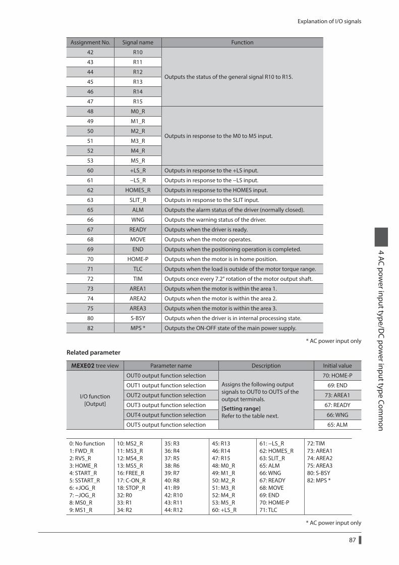
Explanation of I/O signals4 AC pow
er input type/DC pow
er input type Comm
on
87
Assignment No. Signal name Function
42 R10
Outputs the status of the general signal R10 to R15.
43 R11
44 R12
45 R13
46 R14
47 R15
48 M0_R
Outputs in response to the M0 to M5 input.
49 M1_R
50 M2_R
51 M3_R
52 M4_R
53 M5_R
60 +LS_R Outputs in response to the +LS input.
61 −LS_R Outputs in response to the −LS input.
62 HOMES_R Outputs in response to the HOMES input.
63 SLIT_R Outputs in response to the SLIT input.
65 ALM Outputs the alarm status of the driver (normally closed).
66 WNG Outputs the warning status of the driver.
67 READY Outputs when the driver is ready.
68 MOVE Outputs when the motor operates.
69 END Outputs when the positioning operation is completed.
70 HOME-P Outputs when the motor is in home position.
71 TLC Outputs when the load is outside of the motor torque range.
72 TIM Outputs once every 7.2° rotation of the motor output shaft.
73 AREA1 Outputs when the motor is within the area 1.
74 AREA2 Outputs when the motor is within the area 2.
75 AREA3 Outputs when the motor is within the area 3.
80 S-BSY Outputs when the driver is in internal processing state.
82 MPS * Outputs the ON-OFF state of the main power supply.
* AC power input only
Related parameter
MEXE02 tree view Parameter name Description Initial value
I/O function [Output]
OUT0 output function selectionAssigns the following output signals to OUT0 to OUT5 of the output terminals.
[Setting range] Refer to the table next.
70: HOME-P
OUT1 output function selection 69: END
OUT2 output function selection 73: AREA1
OUT3 output function selection 67: READY
OUT4 output function selection 66: WNG
OUT5 output function selection 65: ALM
0: No function 1: FWD_R 2: RVS_R 3: HOME_R 4: START_R 5: SSTART_R 6: +JOG_R 7: −JOG_R 8: MS0_R 9: MS1_R
10: MS2_R 11: MS3_R 12: MS4_R 13: MS5_R 16: FREE_R 17: C-ON_R 18: STOP_R 32: R0 33: R1 34: R2
35: R3 36: R4 37: R5 38: R6 39: R7 40: R8 41: R9 42: R10 43: R11 44: R12
45: R13 46: R14 47: R15 48: M0_R 49: M1_R 50: M2_R 51: M3_R 52: M4_R 53: M5_R 60: +LS_R
61: −LS_R 62: HOMES_R 63: SLIT_R 65: ALM 66: WNG 67: READY 68: MOVE 69: END 70: HOME-P 71: TLC
72: TIM 73: AREA1 74: AREA2 75: AREA3 80: S-BSY 82: MPS *
* AC power input only

Explanation of I/O signals
4 AC power input type/D
C power input type Com
mon
88
1-2 Assignment of remote I/O
Assign the I/O function via RS-485 communication.
Assignment of input signalsThe input signals shown below can be assigned to the NET-IN0 to NET-IN15 of the remote I/O by setting parameters. See each command description for the assignment of the NET-IN0 to NET-IN15.
Assignment No. Signal name Function Setting range
0 No function Sets when the input terminal is not used. −
1 FWDExecutes continuous operation in the positive direction. 0: Deceleration stop
1: Operation2 RVS
Executes continuous operation in the negative direction.
3 HOME Executes return-to-home operation.
0: No operation 1: Start operation
4 START Executes positioning operation.
5 SSTART Executes sequential positioning operation.
6 +JOG Executes JOG operation in the positive direction.
7 −JOG Executes JOG operation in the negative direction.
8 MS0
Executes direct positioning operation of the operation data No. set by the I/O parameter.
9 MS1
10 MS2
11 MS3
12 MS4
13 MS5
16 FREEStops the motor excitation and release the electromagnetic brake.
0: No operation 1: Electromagnetic brake release+motor non- excitation
17 C-ONSwitches the motor excitation between excitation and non-excitation.
0: Motor non-excitation 1: Motor excitation
18 STOP Stops of the motor operation.0: No operation 1: Stop operation
24 ALM-RST * Resets the current alarm.0: No operation 1: Reset alarm
25 P-PRESET * Executes position preset.0: No operation 1: Execute preset
26 P-CLR * Resets the absolute position error alarm.0: No operation 1: Reset alarm
27 HMIReleases of the function limitation of the MEXE02 or OPX-2A
0: Function limitation 1: Function limitation release
32 R0
General signals. Use these signals when controlling the system via RS-485 communication.
0: OFF 1: ON
33 R1
34 R2
35 R3
36 R4
37 R5
38 R6
39 R7
40 R8
41 R9
42 R10

Explanation of I/O signals4 AC pow
er input type/DC pow
er input type Comm
on
89
Assignment No. Signal name Function Setting range
43 R11
General signals. Use these signals when controlling the system via RS-485 communication.
0: OFF 1: ON
44 R12
45 R13
46 R14
47 R15
48 M0
Selects the operation data No. using these six bits. See p.93 for details on the combination.
0: OFF 1: ON (Operation data No.0 to 63 can be selected.)
49 M1
50 M2
51 M3
52 M4
53 M5
* It cannot be set in the driver that is before the specification change. Refer to p.7 for details.
Related parameter
MEXE02 tree view Parameter name Description Initial value
I/O function [RS-485]
NET-IN0 input function selection
Assigns the following input signals to NET-IN0 to NET-IN15.
[Setting range] Refer to the table next.
48: M0
NET-IN1 input function selection 49: M1
NET-IN2 input function selection 50: M2
NET-IN3 input function selection 4: START
NET-IN4 input function selection 3: HOME
NET-IN5 input function selection 18: STOP
NET-IN6 input function selection 16: FREE
NET-IN7 input function selection 0: No function
NET-IN8 input function selection 8: MS0
NET-IN9 input function selection 9: MS1
NET-IN10 input function selection 10: MS2
NET-IN11 input function selection 5: SSTART
NET-IN12 input function selection 6: +JOG
NET-IN13 input function selection 7: −JOG
NET-IN14 input function selection 1: FWD
NET-IN15 input function selection 2: RVS
0: No function 1: FWD 2: RVS 3: HOME 4: START 5: SSTART 6: +JOG
7: −JOG 8: MS0 9: MS1 10: MS2 11: MS3 12: MS4 13: MS5
16: FREE 17: C-ON 18: STOP 24: ALM-RST * 25: P-PRESET * 26: P-CLR * 27: HMI
32: R0 33: R1 34: R2 35: R3 36: R4 37: R5 38: R6
39: R7 40: R8 41: R9 42: R10 43: R11 44: R12 45: R13
46: R14 47: R15 48: M0 49: M1 50: M2 51: M3 52: M4 53: M5
* These three signals cannot be set in the driver which is before the specification change. Refer to p.7 for details.
• Do not assign the same input signal to multiple input terminals. When the same input signal is assigned to multiple input terminals, the function will be executed if any of the terminals becomes active.
• The ALM-RST input and P-CLR input will be executed when turning from ON to OFF. The P-PRESET input will be executed when turning from OFF to ON.
• When the C-ON input and HMI input are not assigned to the input terminals, these inputs will always be set to ON. When assigning to both direct I/O and remote I/O, the function will be executed when both of them are set to ON.
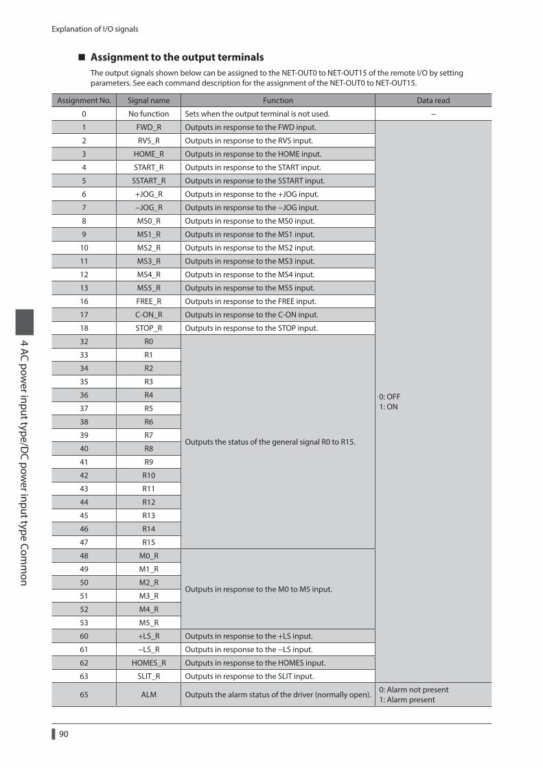
Explanation of I/O signals
4 AC power input type/D
C power input type Com
mon
90
Assignment to the output terminalsThe output signals shown below can be assigned to the NET-OUT0 to NET-OUT15 of the remote I/O by setting parameters. See each command description for the assignment of the NET-OUT0 to NET-OUT15.
Assignment No. Signal name Function Data read
0 No function Sets when the output terminal is not used. −
1 FWD_R Outputs in response to the FWD input.
0: OFF 1: ON
2 RVS_R Outputs in response to the RVS input.
3 HOME_R Outputs in response to the HOME input.
4 START_R Outputs in response to the START input.
5 SSTART_R Outputs in response to the SSTART input.
6 +JOG_R Outputs in response to the +JOG input.
7 −JOG_R Outputs in response to the −JOG input.
8 MS0_R Outputs in response to the MS0 input.
9 MS1_R Outputs in response to the MS1 input.
10 MS2_R Outputs in response to the MS2 input.
11 MS3_R Outputs in response to the MS3 input.
12 MS4_R Outputs in response to the MS4 input.
13 MS5_R Outputs in response to the MS5 input.
16 FREE_R Outputs in response to the FREE input.
17 C-ON_R Outputs in response to the C-ON input.
18 STOP_R Outputs in response to the STOP input.
32 R0
Outputs the status of the general signal R0 to R15.
33 R1
34 R2
35 R3
36 R4
37 R5
38 R6
39 R7
40 R8
41 R9
42 R10
43 R11
44 R12
45 R13
46 R14
47 R15
48 M0_R
Outputs in response to the M0 to M5 input.
49 M1_R
50 M2_R
51 M3_R
52 M4_R
53 M5_R
60 +LS_R Outputs in response to the +LS input.
61 −LS_R Outputs in response to the −LS input.
62 HOMES_R Outputs in response to the HOMES input.
63 SLIT_R Outputs in response to the SLIT input.
65 ALM Outputs the alarm status of the driver (normally open).0: Alarm not present 1: Alarm present

Explanation of I/O signals4 AC pow
er input type/DC pow
er input type Comm
on
91
Assignment No. Signal name Function Data read
66 WNG Outputs the warning status of the driver.0: Warning not present 1: Warning present
67 READY Outputs when the driver is ready.0: Not ready 1: Ready
68 MOVE Outputs when the motor operates.0: Motor stopped 1: Motor operating
69 END Outputs when the positioning operation is completed.0: Motor operating 1: Motor operating completion
70 HOME-P Outputs when the motor is in home position.0: Not home position 1: Home position
71 TLCOutputs when the load is outside of the motor torque range.
0: Inside torque range 1: Outside torque range
72 TIMOutputs once every 7.2° rotation of the motor output shaft.
0: OFF 1: ON
73 AREA1 Outputs when the motor is within the area 1.0: Outside area 1: Inside area
74 AREA2 Outputs when the motor is within the area 2.
75 AREA3 Outputs when the motor is within the area 3.
80 S-BSY Outputs when the driver is in internal processing state. 0: OFF 1: ON82 MPS * Outputs the ON-OFF state of the main power supply.
* AC power input only
Related parameter
MEXE02 tree view Parameter name Description Initial value
I/O function [RS-485]
NET-OUT0 output function selection
Assigns the following output signals to NET-OUT0 to NET-OUT15.
[Setting range] Refer to the table next.
48: M0_R
NET-OUT1 output function selection 49: M1_R
NET-OUT2 output function selection 50: M2_R
NET-OUT3 output function selection 4: START_R
NET-OUT4 output function selection 70: HOME-P
NET-OUT5 output function selection 67: READY
NET-OUT6 output function selection 66: WNG
NET-OUT7 output function selection 65: ALM
NET-OUT8 output function selection 80: S-BSY
NET-OUT9 output function selection 73: AREA1
NET-OUT10 output function selection 74: AREA2
NET-OUT11 output function selection 75: AREA3
NET-OUT12 output function selection 72: TIM
NET-OUT13 output function selection 68: MOVE
NET-OUT14 output function selection 69: END
NET-OUT15 output function selection 71: TLC
0: No function 1: FWD_R 2: RVS_R 3: HOME_R 4: START_R 5: SSTART_R 6: +JOG_R 7: −JOG_R 8: MS0_R 9: MS1_R
10: MS2_R 11: MS3_R 12: MS4_R 13: MS5_R 16: FREE_R 17: C-ON_R 18: STOP_R 32: R0 33: R1 34: R2
35: R3 36: R4 37: R5 38: R6 39: R7 40: R8 41: R9 42: R10 43: R11 44: R12
45: R13 46: R14 47: R15 48: M0_R 49: M1_R 50: M2_R 51: M3_R 52: M4_R 53: M5_R 60: +LS_R
61: −LS_R 62: HOMES_R 63: SLIT_R 65: ALM 66: WNG 67: READY 68: MOVE 69: END 70: HOME-P 71: TLC
72: TIM 73: AREA1 74: AREA2 75: AREA3 80: S-BSY 82: MPS *
* AC power input only
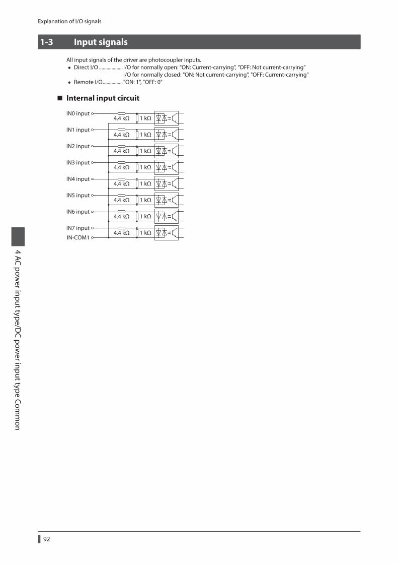
Explanation of I/O signals
4 AC power input type/D
C power input type Com
mon
92
1-3 Input signals
All input signals of the driver are photocoupler inputs. • Direct I/O ................... I/O for normally open: "ON: Current-carrying", "OFF: Not current-carrying"
I/O for normally closed: "ON: Not current-carrying", "OFF: Current-carrying" • Remote I/O ................ "ON: 1", "OFF: 0"
Internal input circuit
IN0 input
IN-COM1
4.4 kΩ 1 kΩ
IN1 input4.4 kΩ 1 kΩ
IN2 input4.4 kΩ 1 kΩ
IN3 input4.4 kΩ 1 kΩ
IN4 input4.4 kΩ 1 kΩ
IN5 input4.4 kΩ 1 kΩ
IN6 input4.4 kΩ 1 kΩ
IN7 input4.4 kΩ 1 kΩ

Explanation of I/O signals4 AC pow
er input type/DC pow
er input type Comm
on
93
M0 to M5 inputsSelect a desired operation data number for positioning operation or continuous operation based on the combination of ON/OFF states of the M0 to M5 inputs.
Operation data No.
M5 M4 M3 M2 M1 M0Operation data
No.M5 M4 M3 M2 M1 M0
0 OFF OFF OFF OFF OFF OFF 32 ON OFF OFF OFF OFF OFF
1 OFF OFF OFF OFF OFF ON 33 ON OFF OFF OFF OFF ON
2 OFF OFF OFF OFF ON OFF 34 ON OFF OFF OFF ON OFF
3 OFF OFF OFF OFF ON ON 35 ON OFF OFF OFF ON ON
4 OFF OFF OFF ON OFF OFF 36 ON OFF OFF ON OFF OFF
5 OFF OFF OFF ON OFF ON 37 ON OFF OFF ON OFF ON
6 OFF OFF OFF ON ON OFF 38 ON OFF OFF ON ON OFF
7 OFF OFF OFF ON ON ON 39 ON OFF OFF ON ON ON
8 OFF OFF ON OFF OFF OFF 40 ON OFF ON OFF OFF OFF
9 OFF OFF ON OFF OFF ON 41 ON OFF ON OFF OFF ON
10 OFF OFF ON OFF ON OFF 42 ON OFF ON OFF ON OFF
11 OFF OFF ON OFF ON ON 43 ON OFF ON OFF ON ON
12 OFF OFF ON ON OFF OFF 44 ON OFF ON ON OFF OFF
13 OFF OFF ON ON OFF ON 45 ON OFF ON ON OFF ON
14 OFF OFF ON ON ON OFF 46 ON OFF ON ON ON OFF
15 OFF OFF ON ON ON ON 47 ON OFF ON ON ON ON
16 OFF ON OFF OFF OFF OFF 48 ON ON OFF OFF OFF OFF
17 OFF ON OFF OFF OFF ON 49 ON ON OFF OFF OFF ON
18 OFF ON OFF OFF ON OFF 50 ON ON OFF OFF ON OFF
19 OFF ON OFF OFF ON ON 51 ON ON OFF OFF ON ON
20 OFF ON OFF ON OFF OFF 52 ON ON OFF ON OFF OFF
21 OFF ON OFF ON OFF ON 53 ON ON OFF ON OFF ON
22 OFF ON OFF ON ON OFF 54 ON ON OFF ON ON OFF
23 OFF ON OFF ON ON ON 55 ON ON OFF ON ON ON
24 OFF ON ON OFF OFF OFF 56 ON ON ON OFF OFF OFF
25 OFF ON ON OFF OFF ON 57 ON ON ON OFF OFF ON
26 OFF ON ON OFF ON OFF 58 ON ON ON OFF ON OFF
27 OFF ON ON OFF ON ON 59 ON ON ON OFF ON ON
28 OFF ON ON ON OFF OFF 60 ON ON ON ON OFF OFF
29 OFF ON ON ON OFF ON 61 ON ON ON ON OFF ON
30 OFF ON ON ON ON OFF 62 ON ON ON ON ON OFF
31 OFF ON ON ON ON ON 63 ON ON ON ON ON ON
START inputThis signal starts the positioning operation.Select the operation data No. and turn the START input to ON to start positioning operation.
Related parameter
MEXE02 tree view Parameter name Description Initial value
AlarmReturn-to-home incomplete alarm
When the positioning operation is started while the position origin has not been set, selects whether the alarm generates or not.
[Setting range] 0: Disable 1: Enable
0

Explanation of I/O signals
4 AC power input type/D
C power input type Com
mon
94
SSTART inputThis signal starts the sequential positioning operation. (p.170)Positioning operation based on the next operation data No. will be performed every time the SSTART input turns ON. This function is useful when multiple positioning operations must be performed sequentially, because there is no need to repeatedly select each operation data No.
Related parameter
MEXE02 tree view Parameter name Description Initial value
AlarmReturn-to-home incomplete alarm
When the positioning operation is started while the position origin has not been set, selects whether the alarm generates or not.
[Setting range] 0: Disable 1: Enable
0
MS0 to MS5 inputThis signal starts the direct positioning operation. (p.169)When any of the MS0 to MS5 inputs is turned ON, the positioning operation corresponding to the input data No. will be performed. Since the positioning operation is enabled by turning any of the MS0 to MS5 inputs ON, you can save the steps of selecting the operation data No.
Related parameter
MEXE02 tree view Parameter name Description Initial value
AlarmReturn-to-home incomplete alarm
When the positioning operation is started while the position origin has not been set, selects whether the alarm generates or not.
[Setting range] 0: Disable 1: Enable
0
I/O
MS0 operation No. selection
Sets operation data No. corresponding to MS0 to MS5 input.
[Setting range] Operation data No.0 to 63
0
MS1 operation No. selection 1
MS2 operation No. selection 2
MS3 operation No. selection 3
MS4 operation No. selection 4
MS5 operation No. selection 5
HOME inputThis signal starts the return-to-home operation. (p.180)Turn the HOME input ON to start return-to-home operation. When the return-to-home operation is completed and the motor stops, the HOME-P output turns ON.
Related parameter
MEXE02 tree view Parameter name Description Initial value
Home operation
Home-seeking mode
Sets the mode for return-to-home operation.
[Setting range] 0: 2-sensor mode 1: 3-sensor mode 2: Push mode
1
Operating speed of home-seeking
Sets the operating speed for return-to-home operation.
[Setting range] 1 to 1,000,000 Hz
1,000

Explanation of I/O signals4 AC pow
er input type/DC pow
er input type Comm
on
95
MEXE02 tree view Parameter name Description Initial value
Home operation
Acceleration/deceleration of home-seeking
Sets the acceleration/deceleration rate (acceleration/deceleration time) for return-to-home operation.
[Setting range] 1 to 1,000,000 (1=0.001 ms/kHz or 1=0.001 s)
1,000
Starting speed of home-seeking
Sets the starting speed for return-to-home operation.
[Setting range] 1 to 1,000,000 Hz
500
Position offset of home-seeking
Sets the amount of offset from mechanical home.
[Setting range] −8,388,608 to 8,388,607 step
0
Starting direction of home-seeking
Sets the starting direction for home detection.
[Setting range] 0: Negative direction 1: Positive direction
1
SLIT detection with home-seeking
Sets whether or not to concurrently use the SLIT input for return-to-home operation.
0: Disable 1: Enable
0
TIM signal detection with home-seeking
Sets whether or not to concurrently use the TIM signal for return-to-home operation.
[Setting range] 0: Disable 1: Enable
0
Operating current of home-seeking with push-motion
Sets the operating current, based on the rated current being 100%, for push-motion return-to-home operation.
[Setting range] 0 to 1,000 (1=0.1%)
1,000
FWD input, RVS inputThese signals start the continuous operation. (p.188)Operation is performed based on the FWD or RVS input and the operating speed corresponding to the selected operation data No.Turn the FWD signal to ON, to perform continuous operation in the positive direction.Turn the RVS signal to ON, to perform continuous operation in the negative direction.If the signal of the same direction is turned ON again during deceleration, the motor will accelerate and continue operating.If the FWD and RVS inputs are turned ON simultaneously, the motor will decelerate to a stop.When the operation data No. is changed during continuous operation, the speed will change to the one specified for the new operation data No.
Explanation of I/O signals
4 AC power input type/D
C power input type Com
mon
96
+JOG input, −JOG inputThese signals start the JOG operation. (p.193)Turn the +JOG signal to ON, to perform JOG operation in the positive direction.Turn the −JOG signal to ON, to perform JOG operation in the negative direction.
Related parameter
MEXE02 tree view Parameter name Description Initial value
Operation
JOG travel amountSets the travel amount for JOG operation.
[Setting range] 1 to 8,388,607 step
1
JOG operating speedSets the operating speed for JOG operation.
[Setting range] 1 to 1,000,000 Hz
1,000
Acceleration/deceleration rate of JOG
Sets the acceleration/deceleration rate (acceleration/deceleration time) for JOG operation.
[Setting range] 1 to 1,000,000 (1=0.001 ms/kHz or 1=0.001 s)
1,000
JOG starting speedSets the starting speed for JOG operation.
[Setting range] 0 to 1,000,000 Hz
500
STOP inputWhen the STOP input turns ON, the motor will stop. When the STOP input turns ON while a positioning operation is being performed, the balance of the travel amount will be cleared. See p.196 for stop action.
Related parameter
MEXE02 tree view Parameter name Description Initial value
I/O STOP input action
Sets how the motor should stop when a STOP input is turned ON.
[Setting range] 0: Immediate stop 1: Deceleration stop 2: Immediate stop & Current OFF 3: Deceleration stop & Current OFF
1
C-ON inputThis signal is used to excite the motor. The motor will be excited when the C-ON input is ON, while the motor will become non-excitation status when the C-ON input is OFF.When an electromagnetic brake motor is used, the electromagnetic brake will be released after the motor is excited.
When the C-ON input is not assigned to the direct I/O or remote I/O, this input will always be set to ON. When assigning to both direct I/O and remote I/O, the function will be executed when both of them are set to ON.
FREE inputWhen the FREE input is turned ON, the motor current will be cut off. The motor will lose its holding torque, and the output shaft can be turned manually. When an electromagnetic brake motor is used, the electromagnetic brake will also be released.
Do not turn the FREE input ON when driving a vertical load. Since the motor loses its holding torque, the load may drop.

Explanation of I/O signals4 AC pow
er input type/DC pow
er input type Comm
on
97
Relations among the status of the FREE input, the C-ON input and the motor output shaft are shown in the tables.
Motor without an electromagnetic brake
C-ON input
FREE inputOFF ON
OFF Output shaft is in a released state Holds output shaft by motor excitation
ON Output shaft is in a released state Output shaft is in a released state
Motor with an electromagnetic brake
C-ON input
FREE inputOFF ON
OFF Holds output shaft by electromagnetic brake Holds output shaft by motor excitation
ON Output shaft is in a released state Output shaft is in a released state
P-PRESET inputThis is a signal for the command position preset.When the P-PRESET input is turned ON, the command position is set as the value of the "Preset position" parameter. (This signal will become effective when turning from OFF to ON.)However, the preset will not execute in the following conditions.
• When an alarm is present. • When the motor is operating.
Related parameter
MEXE02 tree view Parameter name Description Initial value
Coordinates Preset positionSets the preset position.
[Setting range] −8,388,608 to 8,388,607 step
0
ALM-RST inputWhen an alarm generates, the motor will stop. When the ALM-RST input is turned from ON to OFF, the alarm will be reset. (The alarm will be reset at the OFF edge of the ALM-RST input.) Always reset an alarm after removing the cause of the alarm and after ensuring safety.Note that some alarms cannot be reset with the ALM-RST input. See p.143 for alarm descriptions.
P-CLR inputIf the P-CLR input is turned from ON to OFF while an absolute position error alarm is generated, the alarm will be reset. (The alarm will be reset at the OFF edge of the P-CLR input.)The P-CLR input can reset the absolute position error alarm only.
HMI inputWhen the HMI input is turned ON, the function limitation of the MEXE02 or OPX-2A will be released.When the HMI input is turned OFF, the function limitation will be imposed.The following functions will be limited to execute.
• I/O test • Test operation • Teaching • Parameters setting, writing, downloading, initializing • Data setting, clearing, initializing
When the HMI input is not assigned to the input terminal, this input will always be set to ON. When assigning to both direct I/O and remote I/O, the function will be executed when both of them are set to ON.
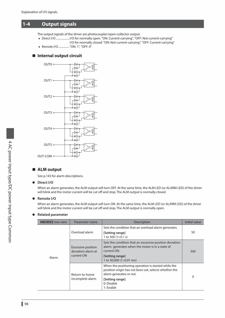
Explanation of I/O signals
4 AC power input type/D
C power input type Com
mon
98
1-4 Output signals
The output signals of the driver are photocoupler/open-collector output. • Direct I/O ................... I/O for normally open: "ON: Current-carrying", "OFF: Not current-carrying"
I/O for normally closed: "ON: Not current-carrying", "OFF: Current-carrying" • Remote I/O ................ "ON: 1", "OFF: 0"
Internal output circuit
OUT0
OUT1
OUT2
OUT3
OUT4
OUT5
OUT-COM
ALM outputSee p.143 for alarm descriptions.
z Direct I/OWhen an alarm generates, the ALM output will turn OFF. At the same time, the ALM LED (or ALARM LED) of the driver will blink and the motor current will be cut off and stop. The ALM output is normally closed.
z Remote I/OWhen an alarm generates, the ALM output will turn ON. At the same time, the ALM LED (or ALARM LED) of the driver will blink and the motor current will be cut off and stop. The ALM output is normally open.
z Related parameter
MEXE02 tree view Parameter name Description Initial value
Alarm
Overload alarmSets the condition that an overload alarm generates.
[Setting range] 1 to 300 (1=0.1 s)
50
Excessive position deviation alarm at current ON
Sets the condition that an excessive position deviation alarm generates when the motor is in a state of current ON.
[Setting range] 1 to 30,000 (1=0.01 rev)
300
Return-to-home incomplete alarm
When the positioning operation is started while the position origin has not been set, selects whether the alarm generates or not.
[Setting range] 0: Disable 1: Enable
0

Explanation of I/O signals4 AC pow
er input type/DC pow
er input type Comm
on
99
MEXE02 tree view Parameter name Description Initial value
AlarmExcessive position deviation alarm at current OFF
Sets the condition that an excessive position deviation alarm generates when the motor is in a state of current OFF. If the position deviation exceeds the setting value in the "Excessive position deviation alarm at current ON" parameter, the excessive position deviation warning at current OFF generates. In addition, if the C-ON input is turned ON, the excessive position deviation alarm at current OFF generates.
[Setting range] 1 to 30,000 (1=0.01 rev)
10,000
Communication
Communication timeout
Sets the condition in which a communication timeout occurs in RS-485 communication. It is not monitored when the set value is 0.
[Setting range] 0: Not monitored 1 to 10,000 ms
0
Communication error alarm
Sets the condition in which a RS-485 communication error alarm generates. A communication error alarm generates after a RS-485 communication error has occurred by the number of times set here.
[Setting range] 1 to 10 times
3
WNG outputWhen a warning generates, the WNG output turns ON. See p.150 for warning descriptions.
Related parameter
MEXE02 tree view Parameter name Description Initial value
Warning
Overheat warning
Sets the condition that a main circuit overheat warning generates.
[Setting range] 40 to 85 °C
85
Overload warning
Sets the condition that an overload warning generates.
[Setting range] 1 to 300 (1=0.1 s)
50
Overspeed warning
Sets the condition that an overspeed warning generates.
[Setting range] 1 to 5,000 r/min
4,500
Overvoltage warning
Sets the condition that an overvoltage warning generates.
[Setting range] AC power input: 120 to 450 V DC power input: 150 to 630 V (1=0.1 V)
AC power input: 435 DC power input: 630
Undervoltage warning
Sets the condition that an undervoltage warning generates.
[Setting range] AC power input: 120 to 280 V DC power input: 150 to 630 V (1=0.1 V)
AC power input: 120 DC power input: 180
Excessive position deviation warning at current ON
Sets the condition that an excessive position deviation warning generates when the motor is in a state of current ON.
[Setting range] 1 to 30,000 (1=0.01 rev)
300

Explanation of I/O signals
4 AC power input type/D
C power input type Com
mon
100
READY outputWhen the driver becomes ready, the READY output turns ON. Input operating commands to the driver after the READY output has turned ON.The READY output turns ON when all of the following conditions are satisfied.
• The driver main power supply is turned ON. • All inputs which start operation are OFF • The FREE input is OFF • The C-ON input is ON (When the C-ON input is assigned) • The STOP input is OFF • An alarm is not present. • The motor is not operating. • Test function, downloading or teaching function was not performed using the MEXE02. • Test operation, downloading, initializing or teaching function was not performed using the OPX-2A. • Configuration commands, all data initialization commands and batch non-volatile memory read commands are
not executed via RS-485 communication.
HOME-P outputThe HOME-P output turns ON corresponding to the setting of the "HOME-P output function selection" parameter. See p.198 for setting the position origin.
z When "HOME-P output function selection" parameter is set to "home output"When the command position of the driver is in the home-position while the MOVE output is OFF, the HOME-P output will turn ON. However, the HOME-P output remains OFF when the position origin for the driver has not been set.
z When "HOME-P output function selection" parameter is set to "return-to-home complete output"Regardless of the command position by the driver, if the position origin for the driver is set, the HOME-P output will turn ON. Therefore, it turns ON after completing the return-to-home operation or preset.Once the HOME-P output turns ON, it will not turn OFF until the motor has moved from the position origin.
When a battery is used, it is charged while the DC power supply is being ON. If the battery runs down or the data retention period passes over in a state where the DC power supply is OFF, the position coordinate will be an unset state (the position origin has been lost).
z Related parameter
MEXE02 tree view Parameter name Description Initial value
I/OHOME-P output function selection
Sets the timing to output the HOME-P output.
[Setting range] 0: Home output 1: Return-to-home complete output
0
MOVE outputThe MOVE output turns ON while the motor is operating.
Related parameter
MEXE02 tree view Parameter name Description Initial value
I/OMinimum ON time for MOVE output
Sets the minimum ON time for MOVE output.
[Setting range] 0 to 255 ms
0

Explanation of I/O signals4 AC pow
er input type/DC pow
er input type Comm
on
101
END outputWhen the motor has completed its movement, the END output will turn ON. When the motor was converged in a position of the "END signal range" parameter against the command position while the MOVE output is in an OFF status, the END output turns ON.
Related parameter
MEXE02 tree view Parameter name Description Initial value
I/O
END signal range
Sets the output range of the END signal (the motor operation converges within this angular range).
[Setting range] 0 to 180 (1=0.1°)
18
Positioning complete output offset
Sets the offset for the END signal (the offset for converging angular range).
[Setting range] −18 to 18 (1=0.1°)
0
TLC outputWhen the load exceeds the motor torque range, the TLC output will turn ON.When performing push-motion operation, if the load exceeds the torque range calculated from the current ratio of push-motion operation, the TLC output will turn ON.This output can be used for the completion signal of the push-motion operation.
AREA1 to AREA3 outputsThe AREA output turns ON when the motor is inside the area set by the parameters.It turns ON when the motor is inside the area even when the motor stops.
Related parameter
MEXE02 tree view Parameter name Description Initial value
I/O
AREA1 positive direction position Sets the AREA1 to AREA3 positive direction position.
[Setting range] −8,388,608 to 8,388,607 step
0AREA2 positive direction position
AREA3 positive direction position
AREA1 negative direction position Sets the AREA1 to AREA3 negative direction position.
[Setting range] −8,388,608 to 8,388,607 step
0AREA2 negative direction position
AREA3 negative direction position
z When the "AREA positive direction position" parameter < "AREA negative direction position" parameter
To turn the AREA output ON: Motor position ≤ AREA positive direction position, or Motor position ≥ AREA negative direction position AREA positive
direction position
AREA output
AREA negativedirection position
ONOFF
z When the "AREA positive direction position" parameter > "AREA negative direction position" parameter
To turn the AREA output ON: AREA negative direction position ≤ Motor position ≤ AREA positive direction position AREA positive
direction position
AREA output
AREA negativedirection position
ONOFF

Explanation of I/O signals
4 AC power input type/D
C power input type Com
mon
102
z When the "AREA positive direction position" parameter = "AREA negative direction position" parameterTo turn the AREA output ON: Motor position = AREA negative direction position = AREA positive direction position
When using AREA1 to AREA3 output to confirm the motor position, you can use two types - the command position and the actual position. AREA1 and AREA2: Command position AREA3: Actual position
TIM outputThe TIM output will turn ON every time the motor output shaft rotates by 7.2°.If the command speed is faster than 30 r/min, TIM output will not be output correctly.
ONOFF
TIM output
Motor operation
ONOFF
Pulse
Motor output shaftrotation by 7.2°
1 20 40 When the resolutionis set to 1,000 P/R
The TIM output is a signal that is output for 50 times per revolution of the motor output shaft. When the TIM output is used, set the resolution to be an integral multiple of 50 using the "Electronic gear" parameters.
S-BSY outputThe S-BSY output turns ON while internal processing of the driver is being executed.In the following condition, the driver will be in an internal processing status.
• Issuing maintenance commands via RS-485 communication
MPS output (AC power input only)The MPS output turns ON when the driver main power is ON.
Response outputThe response output is the output signal that shows the ON/OFF status corresponding to the input signals.The tables show the correspondence between the input signals and output signals.
Input signal Output signal Input signal Output signal Input signal Output signal
FWD FWD_R MS2 MS2_R M2 M2_R
RVS RVS_R MS3 MS3_R M3 M3_R
HOME HOME_R MS4 MS4_R M4 M4_R
START START_R MS5 MS5_R M5 M5_R
SSTART SSTART_R FREE FREE_R +LS +LS_R
+JOG +JOG_R C-ON C-ON_R −LS −LS_R
−JOG −JOG_R STOP STOP_R HOMES HOMES_R
MS0 MS0_R M0 M0_R SLIT SLIT_R
MS1 MS1_R M1 M1_R
The response output is the output signal to return the status of the input signal. Therefore, the output signals corresponding to the input signals for motor operation (START_R output etc.) do not show the movement of the motor itself.
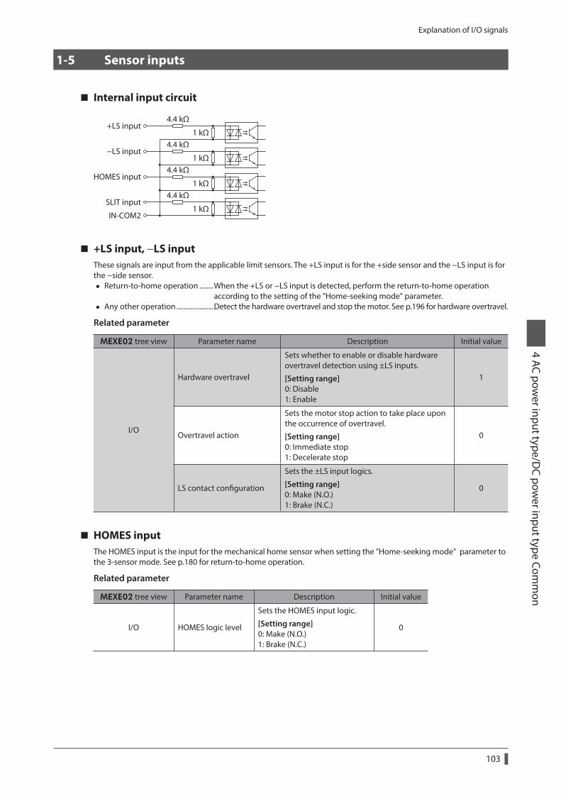
Explanation of I/O signals4 AC pow
er input type/DC pow
er input type Comm
on
103
1-5 Sensor inputs
Internal input circuit
+LS input
IN-COM2
4.4 kΩ
1 kΩ
-LS input4.4 kΩ
1 kΩ
HOMES input4.4 kΩ
1 kΩ
SLIT input4.4 kΩ
1 kΩ
+LS input, −LS inputThese signals are input from the applicable limit sensors. The +LS input is for the +side sensor and the −LS input is for the −side sensor.
• Return-to-home operation ........When the +LS or −LS input is detected, perform the return-to-home operation according to the setting of the "Home-seeking mode" parameter.
• Any other operation .....................Detect the hardware overtravel and stop the motor. See p.196 for hardware overtravel.
Related parameter
MEXE02 tree view Parameter name Description Initial value
I/O
Hardware overtravel
Sets whether to enable or disable hardware overtravel detection using ±LS inputs.
[Setting range] 0: Disable 1: Enable
1
Overtravel action
Sets the motor stop action to take place upon the occurrence of overtravel.
[Setting range] 0: Immediate stop 1: Decelerate stop
0
LS contact configuration
Sets the ±LS input logics.
[Setting range] 0: Make (N.O.) 1: Brake (N.C.)
0
HOMES inputThe HOMES input is the input for the mechanical home sensor when setting the "Home-seeking mode" parameter to the 3-sensor mode. See p.180 for return-to-home operation.
Related parameter
MEXE02 tree view Parameter name Description Initial value
I/O HOMES logic level
Sets the HOMES input logic.
[Setting range] 0: Make (N.O.) 1: Brake (N.C.)
0

Explanation of I/O signals
4 AC power input type/D
C power input type Com
mon
104
SLIT inputConnect the SLIT input when using motorized linear slides equipped with a slit.When detecting the home, use of the SLIT input in addition to the HOMES will increase the accuracy of home detection. See p.180 for return-to-home operation.
Related parameter
MEXE02 tree view Parameter name Description Initial value
I/O SLIT logic level
Sets the SLIT input logic.
[Setting range] 0: Make (N.O.) 1: Brake (N.C.)
0
1-6 General signals (R0 to R15)
R0 to R15 are general signals that enable control via RS-485 communication.Using R0 to R15, I/O signals for the external device can be controlled by the master controller via the driver.The direct I/O of the driver can be used as an I/O unit.See the following example for setting of the general signals.
z When outputting the signals from the master controller to the external deviceAssign the general signal R0 to the OUT0 output and NET-IN0.When setting the NET-IN0 to 1, the OUT0 output turns ON. When setting the NET-IN0 to 0, the OUT0 output turns OFF.
z When inputting the output of the external device to the master controllerAssign the general signal R1 to the IN7 input and NET-OUT15.When turning the IN7 input ON by the external device, the NET-OUT15 becomes 1. When turning the IN7 input OFF, the NET-OUT15 becomes 0. The logic level of the IN7 input can be set using "IN7 input logic level setting" parameter.
Mastercontroller
DriverSwitchSensor
etc.
RS-485 communication
RS-485 communicationDirect I/O
RS-485 communication
R0 (NET-IN0)
R1 (NET-OUT15)
I/O
I/O
R0 (OUT0)
R1 (IN7)
* The figure shows the AC power input.

Method of control via I/O4 AC pow
er input type/DC pow
er input type Comm
on
105
2 Method of control via I/O
2-1 Guidance
If you are new to the AR Series FLEX built-in controller type, read this section to understand the operating methods along with the operation flow.
Before operating the motor, check the condition of the surrounding area to ensure safety.
AC power input
STEP 1 Check the installation and connection
CheckSTART input connectionCheck
Motor connection
Check24 VDC power supply connection
CheckMain power supply connection
Mastercontroller Or
CheckMEXE02 or OPX-2A connection
OPX-2APC in which the MEXE02
has been installed
Check
Grounding
Check
Grounding
STEP 2 Turn on the power and set the operation data
Set the operation datacorresponding to one motorrevolution using the MEXE02 or OPX-2A.• Position No.0: 1,000 step
MEXE02OPX-2A
2. Turn on the main power supply.
1. Turn on the 24 VDC power supply.
Or
Grounding

Method of control via I/O
4 AC power input type/D
C power input type Com
mon
106
STEP 3 Operate the motor
2. Check the motor rotates according to the setting.
1. Turn the START input ON.
MEXE02OPX-2A
OrMaster
controller
Grounding
STEP 4 Were you able to operate the motor properly?
How did it go? Were you able to operate the motor properly? If the motor does not function, check the following points:
• Are the regeneration resistor thermal input terminals (TH1 and TH2) on the CN1 short-circuited? • Is any alarm present? • Are the power supply and motor connected securely?
For more detailed settings and functions, refer to "5 Operation type and setting" on p.153.

Method of control via I/O4 AC pow
er input type/DC pow
er input type Comm
on
107
DC power input
STEP 1 Check the installation and connection
CheckSTART input connection
CheckPower supply connection
Master controller
Or
OPX-2A
Check
Grounding
Check
Grounding
PC in which the MEXE02has been installed
CheckMEXE02 or OPX-2A connection
CheckMotor connection
STEP 2 Turn on the power and set the operation data
Turn on the power supply.
MEXE02OPX-2A
Or
Set the operation datacorresponding to one motorrevolution using the MEXE02 or OPX-2A.• Position No.0: 1,000 step
Grounding

Method of control via I/O
4 AC power input type/D
C power input type Com
mon
108
STEP 3 Operate the motor
1. Turn the START input ON.
2. Check the motor rotates according to the setting.
Or
Master controller
MEXE02OPX-2A
Grounding
STEP 4 Were you able to operate the motor properly?
How did it go? Were you able to operate the motor properly? If the motor does not function, check the following points:
• Is any alarm present? • Are the power supply and motor connected securely?
For more detailed settings and functions, refer to "5 Operation type and setting" on p.153.

Method of control via I/O4 AC pow
er input type/DC pow
er input type Comm
on
109
2-2 Operation data
Up to 64 operation data can be set (data Nos.0 to 63).If the data is changed, a recalculation and setup will be performed after the operation is stopped.
Data Description Initial value
Position No.0 to
Position No.63
Sets the position (distance) for positioning operation.
[Setting range] −8,388,608 to +8,388,607 step
0
Operating speed No.0 to
Operating speed No.63
Sets the operating speed in positioning operation and continuous operation.
[Setting range] 0 to 1,000,000 Hz
1,000
Operation mode No.0 to
Operation mode No.63
Selects how to specify the position (travel amount) in positioning operation.
[Setting range] 0: Incremental (INC) 1: Absolute (ABS)
0
Operation function No.0 to
Operation function No.63
Sets the operation mode to execute positioning operation.
[Setting range] 0: Single-motion 1: Linked-motion 2: Linked-motion 2 3: Push
0
Acceleration No.0 to
Acceleration No.63
Sets the acceleration rate (acceleration time) in positioning operation and continuous operation. *1
[Setting range] 1 to 1,000,000 (1=0.001 ms/kHz or 1=0.001 s) *2
1,000
Deceleration No.0 to
Deceleration No.63
Sets the deceleration rate (deceleration time) in positioning operation and continuous operation. *1
[Setting range] 1 to 1,000,000 (1=0.001 ms/kHz or 1=0.001 s) *2
1,000
Push current No.0 to
Push current No.63
Sets the current rate of push-motion operation.
[Setting range] 0 to 1,000 (1=0.1%) *3
200
Sequential positioning No.0 to
Sequential positioning No.63
Sets whether to enable or disable sequential positioning operation.
[Setting range] 0: Disable 1: Enable
0
Dwell time No.0 to
Dwell time No.63
Sets the dwell time to be used in linked-motion 2 operation.
[Setting range] 0 to 50,000 (1=0.001 s)
0
*1 This item is effective when the “Acceleration/deceleration type” parameter is set to “separate.” If this parameter is set to “common,” the values of the “Common acceleration” and “Common deceleration” parameters will be used (initial value: separate).
*2 Acceleration/deceleration rate (ms/kHz) or acceleration/deceleration time (s) can be selected using "Acceleration/deceleration unit" parameter (initial value: ms/kHz).
*3 For the driver which is before the specification change, the setting range is 0 to 500 (1=0.1%). Refer to p.7 for details.

Method of control via I/O
4 AC power input type/D
C power input type Com
mon
110
2-3 Parameter
The parameters are saved in the RAM or non-volatile memory. The data saved in the RAM will be erased once the DC power supply is turned off. On the other hand, the parameters saved in the non-volatile memory will be retained even after the DC power supply is turned off.When turning the driver DC power supply on, the parameters saved in the non-volatile memory will be sent to the RAM. Then, the recalculation and setup for the parameters are executed in the RAM.
Parameters having set via RS-485 communication or industrial network are saved in the RAM. To save the parameters stored in the RAM to the non-volatile memory, execute the "Batch non-volatile memory write" of the maintenance command.The parameters set with the MEXE02 will be saved in the non-volatile memory if "data writing" is performed.
When a parameter is changed, the timing to update the new value varies depending on the parameter. See the following four types.
Update timing Description
A ImmediatelyExecutes the recalculation and setup immediately when writing the parameter.
B After stopping the operation Executes the recalculation and setup after stopping the operation.
CAfter executing the configuration or cycling the power
Executes the recalculation and setup after executing the configuration or cycling the DC power supply.
D After cycle the power Executes the recalculation and setup after cycling the DC power supply.
In this chapter, each update timing is represented in A to D.
• Parameters set via RS-485 communication or industrial network are saved in the RAM. If parameters, which are required turning on the power again in order to update, are changed, be sure to save them in the non-volatile memory before turning off the power.
• The non-volatile memory can be rewritten approximately 100,000 times.
Parameter list
I/O parameter (p.112)
• STOP input action
•Hardware overtravel
•Overtravel action
• END signal range
• Positioning complete output offset
•AREA1 positive direction position
•AREA1 negative direction position
•AREA2 positive direction position
•AREA2 negative direction position
•AREA3 positive direction position
•AREA3 negative direction position
•Minimum ON time for MOVE output
• LS contact configuration
•HOMES logic level
• SLIT logic level
•MS0 operation No. selection
•MS1 operation No. selection
•MS2 operation No. selection
•MS3 operation No. selection
•MS4 operation No. selection
•MS5 operation No. selection
•HOME-P output function selection
Motor parameter (p.113)
• RUN current
• STOP current
• Position loop gain
• Speed loop gain
• Speed loop integral time constant
• Speed filter
•Moving average time
• Filter selection
• Speed difference gain 1
• Speed difference gain 2
•Control mode
• Smooth drive

Method of control via I/O4 AC pow
er input type/DC pow
er input type Comm
on
111
Operation parameter (p.114)
•Common acceleration
•Common deceleration
• Starting speed
• JOG operating speed
•Acceleration/deceleration rate of JOG
• JOG starting speed
•Acceleration/deceleration type
•Acceleration/deceleration unit
•Automatic return operation
•Operation speed of automatic return
•Acceleration (deceleration) of automatic return
• Starting speed of automatic return
• JOG travel amount
Home operation parameter (p.115)
•Home-seeking mode
•Operating speed of home-seeking
•Acceleration/deceleration of home-seeking
• Starting speed of home-seeking
• Position offset of home-seeking
• Starting direction of home-seeking
• SLIT detection with home-seeking
• TIM signal detection with home-seeking
•Operating current of home-seeking with push-motion
Alarm parameter (p.116) •Overload alarm
• Excessive position deviation alarm at current ON
• Return-to-home incomplete alarm
• Excessive position deviation alarm at current OFF
Warning parameter (p.116)
•Overheat warning
•Overload warning
•Overspeed warning
•Overvoltage warning
•Undervoltage warning
• Excessive position deviation warning at current ON
Coordinates parameter (p.117)
• Electronic gear A
• Electronic gear B
•Motor rotation direction
• Software overtravel
• Positive software limit
•Negative software limit
• Preset position
•Wrap setting
•Wrap setting range
Common parameter (p.117)
•Data setter speed display
•Data setter edit
•Absolute back-up system
I/O function [input] parameter (p.118)
• IN0 to IN7 input function selection
• IN0 to IN7 input logic level setting
I/O function [output] parameter (p.118)
•OUT0 to OUT5 output function selection
I/O function [RS-485] parameter (p.119)
•NET-IN0 to NET-IN15 input function selection
•NET-OUT0 to NET-OUT15 output function selection
Communication parameter (p.120)
•Communication timeout
•Communication error alarm
•Communication parity
•Communication stop bit
• Transmission waiting time

Method of control via I/O
4 AC power input type/D
C power input type Com
mon
112
I/O parameter
Parameter name Description Initial valueUpdate (p.110)
STOP input action
Sets how the motor should stop when a STOP input is turned ON.
[Setting range] 0: Immediate stop 1: Decelerate stop 2: Immediate stop & Current OFF 3: Deceleration stop & Current OFF
1
A
Hardware overtravel
Sets whether to enable or disable hardware overtravel detection using ±LS inputs.
[Setting range] 0: Disable 1: Enable
1
Overtravel action
Sets the motor stop action to take place upon the occurrence of overtravel.
[Setting range] 0: Immediate stop 1: Decelerate stop
0
END signal range
Sets the output range of the END signal (the motor operation converges within this angular range).
[Setting range] 0 to 180 (1=0.1°)
18
Positioning complete output offset
Sets the offset for the END signal (the offset for converging angular range).
[Setting range] −18 to 18 (1=0.1°)
0
AREA1 positive direction position
Sets the AREA1 to AREA3 positive direction position.
[Setting range] −8,388,608 to 8,388,607 step
0AREA2 positive direction position
AREA3 positive direction position
AREA1 negative direction position
Sets the AREA1 to AREA3 negative direction position.
[Setting range] −8,388,608 to 8,388,607 step
0AREA2 negative direction position
AREA3 negative direction position
Minimum ON time for MOVE output
Sets the minimum ON time for MOVE output.
[Setting range] 0 to 255 ms
0
LS contact configuration
Sets the ±LS input logics.
[Setting range] 0: Make (N.O.) 1: Brake (N.C.)
0
CHOMES logic level
Sets the HOMES input logic.
[Setting range] 0: Make (N.O.) 1: Brake (N.C.)
0
SLIT logic level
Sets the SLIT input logic.
[Setting range] 0: Make (N.O.) 1: Brake (N.C.)
0
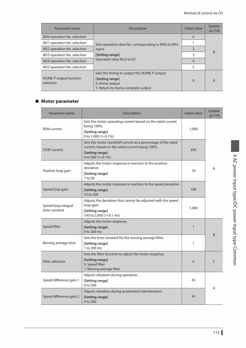
Method of control via I/O4 AC pow
er input type/DC pow
er input type Comm
on
113
Parameter name Description Initial valueUpdate (p.110)
MS0 operation No. selection
Sets operation data No. corresponding to MS0 to MS5 input.
[Setting range] Operation data No.0 to 63
0
B
MS1 operation No. selection 1
MS2 operation No. selection 2
MS3 operation No. selection 3
MS4 operation No. selection 4
MS5 operation No. selection 5
HOME-P output function selection
Sets the timing to output the HOME-P output.
[Setting range] 0: Home output 1: Return-to-home complete output
0 A
Motor parameter
Parameter name Description Initial valueUpdate (p.110)
RUN current
Sets the motor operating current based on the rated current being 100%.
[Setting range] 0 to 1,000 (1=0.1%)
1,000
A
STOP current
Sets the motor standstill current as a percentage of the rated current, based on the rated current being 100%.
[Setting range] 0 to 500 (1=0.1%)
500
Position loop gain
Adjusts the motor response in reaction to the position deviation.
[Setting range] 1 to 50
10
Speed loop gainAdjusts the motor response in reaction to the speed deviation.
[Setting range] 10 to 200
180
Speed loop integral time constant
Adjusts the deviation that cannot be adjusted with the speed loop gain.
[Setting range] 100 to 2,000 (1=0.1 ms)
1,000
Speed filterAdjusts the motor response.
[Setting range] 0 to 200 ms
1
B
Moving average timeSets the time constant for the moving average filter.
[Setting range] 1 to 200 ms
1
Filter selection
Sets the filter function to adjust the motor response.
[Setting range] 0: Speed filter 1: Moving average filter
0 C
Speed difference gain 1Adjusts vibration during operation.
[Setting range] 0 to 500
45
A
Speed difference gain 2Adjusts vibration during acceleration/deceleration.
[Setting range] 0 to 500
45

Method of control via I/O
4 AC power input type/D
C power input type Com
mon
114
Parameter name Description Initial valueUpdate (p.110)
Control mode
Sets the control mode of the driver.
[Setting range] 0: Normal mode 1: Current control mode
0
C
Smooth drive
Sets whether to enable or disable smooth drive function.
[Setting range] 0: Disable 1: Enable
1
Operation parameter
Parameter name Description Initial valueUpdate (p.110)
Common acceleration
Sets the common acceleration rate (common acceleration time) in positioning operation and continuous operation.
[Setting range] 1 to 1,000,000 (1=0.001 ms/kHz or 1=0.001 s) *
1,000
B
Common deceleration
Sets the common deceleration rate (common deceleration time) in positioning operation and continuous operation.
[Setting range] 1 to 1,000,000 (1=0.001 ms/kHz or 1=0.001 s) *
1,000
Starting speed
Sets the starting speed in positioning operation and continuous operation. The motor will operate at the starting speed if the operating speed is below the starting speed.
[Setting range] 0 to 1,000,000 Hz
500
JOG operating speed
Sets the operating speed for JOG operation.
[Setting range] 1 to 1,000,000 Hz
1,000
Acceleration/deceleration rate of JOG
Sets the acceleration/deceleration rate (acceleration/deceleration time) for JOG operation.
[Setting range] 1 to 1,000,000 (1=0.001 ms/kHz or 1=0.001 s) *
1,000
JOG starting speedSets the starting speed for JOG operation.
[Setting range] 0 to 1,000,000 Hz
500
Acceleration/deceleration type
Sets whether to use the common acceleration/deceleration or the acceleration/deceleration specified for the operation data.
[Setting range] 0: Common 1: Separate
1
Acceleration/deceleration unit
Sets the acceleration/deceleration unit.
[Setting range] 0: ms/kHz 1: s
0
C
Automatic return operation
Sets whether to enable or disable automatic return operation.
[Setting range] 0: Disable 1: Enable
0
Operation speed of automatic return
Sets the operating speed for automatic return operation.
[Setting range] 1 to 1,000,000 Hz
1,000 B

Method of control via I/O4 AC pow
er input type/DC pow
er input type Comm
on
115
Parameter name Description Initial valueUpdate (p.110)
Acceleration (deceleration) of automatic return
Sets the acceleration/deceleration rate (acceleration/deceleration time) for automatic return operation.
[Setting range] 1 to 1,000,000 (1=0.001 ms/kHz or 1=0.001 s) *
1,000
BStarting speed of automatic return
Sets the starting speed for automatic return operation.
[Setting range] 0 to 1,000,000 Hz
500
JOG travel amountSets the travel amount for JOG operation.
[Setting range] 1 to 8,388,607 step
1
* Acceleration/deceleration rate (ms/kHz) or acceleration/deceleration time (s) can be selected using "Acceleration/deceleration unit" parameter (initial value: acceleration/deceleration rate).
Home operation parameter
Parameter name Description Initial valueUpdate (p.110)
Home-seeking mode
Sets the mode for return-to-home operation.
[Setting range] 0: 2-sensor mode 1: 3-sensor mode 2: Push mode
1
B
Operating speed of home-seeking
Sets the operating speed for return-to-home operation.
[Setting range] 1 to 1,000,000 Hz
1,000
Acceleration/deceleration of home-seeking
Sets the acceleration/ deceleration rate (acceleration/deceleration time) for return-to-home operation.
[Setting range] 1 to 1,000,000 (1=0.001 ms/kHz or 1=0.001 s) *
1,000
Starting speed of home-seeking
Sets the starting speed for return-to-home operation.
[Setting range] 1 to 1,000,000 Hz
500
Position offset of home-seeking
Sets the amount of offset from mechanical home.
[Setting range] −8,388,608 to 8,388,607 step
0
Starting direction of home-seeking
Sets the starting direction for home detection.
[Setting range] 0: Negative direction 1: Positive direction
1
SLIT detection with home-seeking
Sets whether or not to concurrently use the SLIT input for return-to-home operation.
[Setting range] 0: Disable 1: Enable
0
TIM signal detection with home-seeking
Sets whether or not to concurrently use the TIM signal for return-to-home operation.
[Setting range] 0: Disable 1: Enable
0
Operating current of home-seeking with push-motion
Sets the operating current for push-motion return-to-home operation based on the rated current being 100%.
[Setting range] 0 to 1,000 (1=0.1%)
1,000
* Acceleration/deceleration rate (ms/kHz) or acceleration/deceleration time (s) can be selected using "Acceleration/deceleration unit" parameter (initial value: acceleration/deceleration rate).

Method of control via I/O
4 AC power input type/D
C power input type Com
mon
116
Alarm parameter
Parameter name Description Initial valueUpdate (p.110)
Overload alarmSets the condition that an overload alarm generates.
[Setting range] 1 to 300 (1=0.1 s)
50
AExcessive position deviation alarm at current ON
Sets the condition that an excessive position deviation alarm generates when the motor is in a state of current ON.
[Setting range] 1 to 30,000 (1=0.01 rev)
300
Return-to-home incomplete alarm
When the positioning operation is started while the position origin has not been set, selects whether the alarm generates or not.
[Setting range] 0: Disable 1: Enable
0 C
Excessive position deviation alarm at current OFF
Sets the condition that an excessive position deviation alarm generates when the motor is in a state of current OFF. If the position deviation exceeds the setting value in the "Excessive position deviation alarm at current ON" parameter, the excessive position deviation warning at current OFF generates. In addition, if the C-ON input is turned ON, the excessive position deviation alarm at current OFF generates.
[Setting range] 1 to 30,000 (1=0.01 rev)
10,000 A
Warning parameter
Parameter name Description Initial valueUpdate (p.110)
Overheat warning
Sets the condition that a main circuit overheat warning generates.
[Setting range] 40 to 85 °C
85
A
Overload warningSets the condition that an overload warning generates.
[Setting range] 1 to 300 (1=0.1 s)
50
Overspeed warningSets the condition that an overspeed warning generates.
[Setting range] 1 to 5,000 r/min
4,500
Overvoltage warning (AC power input)
Sets the condition that an overvoltage warning generates.
[Setting range] 120 to 450 V
435
Overvoltage warning (DC power input)
Sets the condition that an overvoltage warning generates.
[Setting range] 150 to 630 (1=0.1 V)
630
Undervoltage warning (AC power input)
Sets the condition that an undervoltage warning generates.
[Setting range] 120 to 280 V
120
Undervoltage warning (DC power input)
Sets the condition that an undervoltage warning generates.
[Setting range] 150 to 630 (1=0.1 V)
180
Excessive position deviation warning at current ON
Sets the condition that an excessive position deviation warning generates when the motor is in a state of current ON.
[Setting range] 1 to 30,000 (1=0.01 rev)
300

Method of control via I/O4 AC pow
er input type/DC pow
er input type Comm
on
117
Coordinates parameter
Parameter name Description Initial valueUpdate (p.110)
Electronic gear ASets the denominator of electronic gear.
[Setting range] 1 to 65,535
1
CElectronic gear B
Sets the numerator of electronic gear.
[Setting range] 1 to 65,535
1
Motor rotation direction
Sets the rotation direction of motor output shaft.
[Setting range] 0: Positive direction=CCW 1: Positive direction=CW
1
Software overtravel
Sets whether to enable or disable software overtravel detection using soft limits.
[Setting range] 0: Disable 1: Enable
1
APositive software limit
Sets the value of soft limit in positive direction.
[Setting range] −8,388,608 to 8,388,607 step
8,388,607
Negative software limitSets the value of soft limit in negative direction.
[Setting range] −8,388,608 to 8,388,607 step
−8,388,608
Preset positionSets the preset position.
[Setting range] −8,388,608 to 8,388,607 step
0
Wrap setting
Sets whether to enable or disable wrap function.
[Setting range] 0: Disable 1: Enable
0
C
Wrap setting rangeSets the wrap setting range.
[Setting range] 1 to 8,388,607 step
1,000
Common parameter
Parameter name Description Initial valueUpdate (p.110)
Data setter speed display
Sets the display method of the speed monitor for the OPX-2A.
[Setting range] 0: Signed 1: Absolute value
0
A
Data setter edit
Sets whether it is possible to edit using the OPX-2A.
[Setting range] 0: Disable 1: Enable
1
Absolute back-up system
Sets whether to enable or disable absolute-position backup system.
[Setting range] 0: Disable 1: Enable
0 C
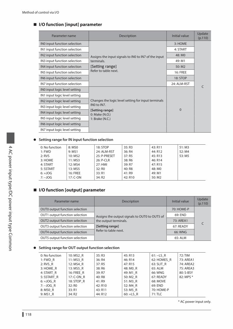
Method of control via I/O
4 AC power input type/D
C power input type Com
mon
118
I/O function [input] parameter
Parameter name Description Initial valueUpdate (p.110)
IN0 input function selection
Assigns the input signals to IN0 to IN7 of the input terminals.
[Setting range] Refer to table next.
3: HOME
C
IN1 input function selection 4: START
IN2 input function selection 48: M0
IN3 input function selection 49: M1
IN4 input function selection 50: M2
IN5 input function selection 16: FREE
IN6 input function selection 18: STOP
IN7 input function selection 24: ALM-RST
IN0 input logic level setting
Changes the logic level setting for input terminals IN0 to IN7.
[Setting range] 0: Make (N.O.) 1: Brake (N.C.)
0
IN1 input logic level setting
IN2 input logic level setting
IN3 input logic level setting
IN4 input logic level setting
IN5 input logic level setting
IN6 input logic level setting
IN7 input logic level setting
z Setting range for IN input function selection
0: No function 1: FWD 2: RVS 3: HOME 4: START 5: SSTART 6: +JOG 7: −JOG
8: MS0 9: MS1 10: MS2 11: MS3 12: MS4 13: MS5 16: FREE 17: C-ON
18: STOP 24: ALM-RST 25: P-PRESET 26: P-CLR 27: HMI 32: R0 33: R1 34: R2
35: R3 36: R4 37: R5 38: R6 39: R7 40: R8 41: R9 42: R10
43: R11 44: R12 45: R13 46: R14 47: R15 48: M0 49: M1 50: M2
51: M3 52: M4 53: M5
I/O function [output] parameter
Parameter name Description Initial valueUpdate (p.110)
OUT0 output function selection
Assigns the output signals to OUT0 to OUT5 of the output terminals.
[Setting range] Refer to table next.
70: HOME-P
C
OUT1 output function selection 69: END
OUT2 output function selection 73: AREA1
OUT3 output function selection 67: READY
OUT4 output function selection 66: WNG
OUT5 output function selection 65: ALM
z Setting range for OUT output function selection
0: No function 1: FWD_R 2: RVS_R 3: HOME_R 4: START_R 5: SSTART_R 6: +JOG_R 7: −JOG_R 8: MS0_R 9: MS1_R
10: MS2_R 11: MS3_R 12: MS4_R 13: MS5_R 16: FREE_R 17: C-ON_R 18: STOP_R 32: R0 33: R1 34: R2
35: R3 36: R4 37: R5 38: R6 39: R7 40: R8 41: R9 42: R10 43: R11 44: R12
45: R13 46: R14 47: R15 48: M0_R 49: M1_R 50: M2_R 51: M3_R 52: M4_R 53: M5_R 60: +LS_R
61: −LS_R 62: HOMES_R 63: SLIT_R 65: ALM 66: WNG 67: READY 68: MOVE 69: END 70: HOME-P 71: TLC
72: TIM 73: AREA1 74: AREA2 75: AREA3 80: S-BSY 82: MPS *
* AC power input only.

Method of control via I/O4 AC pow
er input type/DC pow
er input type Comm
on
119
I/O function [RS-485] parameter
Parameter name Description Initial valueUpdate (p.110)
NET-IN0 input function selection
Assigns the input signals to NET-IN0 to NET-IN15.
[Setting range] Refer to "Setting range for NET-IN input function selection".
48: M0
C
NET-IN1 input function selection 49: M1
NET-IN2 input function selection 50: M2
NET-IN3 input function selection 4: START
NET-IN4 input function selection 3: HOME
NET-IN5 input function selection 18: STOP
NET-IN6 input function selection 16: FREE
NET-IN7 input function selection 0: No function
NET-IN8 input function selection 8: MS0
NET-IN9 input function selection 9: MS1
NET-IN10 input function selection 10: MS2
NET-IN11 input function selection 5: SSTART
NET-IN12 input function selection 6: +JOG
NET-IN13 input function selection 7: −JOG
NET-IN14 input function selection 1: FWD
NET-IN15 input function selection 2: RVS
NET-OUT0 output function selection
Assigns the output signals to NET-OUT0 to NET-OUT15.
[Setting range] Refer to "Setting range for NET-OUT output function selection" on p.120.
48: M0_R
NET-OUT1 output function selection 49: M1_R
NET-OUT2 output function selection 50: M2_R
NET-OUT3 output function selection 4: START_R
NET-OUT4 output function selection 70: HOME-P
NET-OUT5 output function selection 67: READY
NET-OUT6 output function selection 66: WNG
NET-OUT7 output function selection 65: ALM
NET-OUT8 output function selection 80: S-BSY
NET-OUT9 output function selection 73: AREA1
NET-OUT10 output function selection 74: AREA2
NET-OUT11 output function selection 75: AREA3
NET-OUT12 output function selection 72: TIM
NET-OUT13 output function selection 68: MOVE
NET-OUT14 output function selection 69: END
NET-OUT15 output function selection 71: TLC
z Setting range for NET-IN input function selection
0: No function 1: FWD 2: RVS 3: HOME 4: START 5: SSTART 6: +JOG
7: −JOG 8: MS0 9: MS1 10: MS2 11: MS3 12: MS4 13: MS5
16: FREE 17: C-ON 18: STOP 24: ALM-RST * 25: P-PRESET * 26: P-CLR * 27: HMI
32: R0 33: R1 34: R2 35: R3 36: R4 37: R5 38: R6
39: R7 40: R8 41: R9 42: R10 43: R11 44: R12 45: R13
46: R14 47: R15 48: M0 49: M1 50: M2 51: M3 52: M4 53: M5
* It cannot be set in the driver that is before the specification change. Refer to p.7 for details.

Method of control via I/O
4 AC power input type/D
C power input type Com
mon
120
z Setting range for NET-OUT output function selection
0: No function 1: FWD_R 2: RVS_R 3: HOME_R 4: START_R 5: SSTART_R 6: +JOG_R 7: −JOG_R 8: MS0_R 9: MS1_R
10: MS2_R 11: MS3_R 12: MS4_R 13: MS5_R 16: FREE_R 17: C-ON_R 18: STOP_R 32: R0 33: R1 34: R2
35: R3 36: R4 37: R5 38: R6 39: R7 40: R8 41: R9 42: R10 43: R11 44: R12
45: R13 46: R14 47: R15 48: M0_R 49: M1_R 50: M2_R 51: M3_R 52: M4_R 53: M5_R 60: +LS_R
61: −LS_R 62: HOMES_R 63: SLIT_R 65: ALM 66: WNG 67: READY 68: MOVE 69: END 70: HOME-P 71: TLC
72: TIM 73: AREA1 74: AREA2 75: AREA3 80: S-BSY 82: MPS *
* AC power input only.
Communication parameter
Parameter name Description Initial valueUpdate (p.110)
Communication timeout
Sets the condition in which a communication timeout occurs in RS-485 communication. It is not monitored when the set value is 0.
[Setting range] 0: Not monitored 1 to 10,000 ms
0
A
Communication error alarm
Sets the condition in which a RS-485 communication error alarm generates. A communication error alarm generates after a RS-485 communication error has occurred by the number of times set here.
[Setting range] 1 to 10 times
3
Communication parity
Sets the parity of RS-485 communication.
[Setting range] 0: None 1: Even 2: Odd
1
DCommunication stop bit
Sets the stop bit of RS-485 communication.
[Setting range] 0: 1 bit 1: 2 bits
0
Transmission waiting time
Sets the transmission waiting time of RS-485 communication.
[Setting range] 0 to 10,000 (1=0.1 ms)
100

4 AC power input type/D
C power input type Com
mon
121
3 Operation using the OPX-2A
This chapter explains the overview and operating method for the OPX-2A.When connect or disconnect the OPX-2A cable, turn off the driver power supply.
3-1 Overview of the OPX-2A
The OPX-2A is a data setter that can set the operation data and parameters, and execute monitor and others. In addition, the OPX-2A can be used to save the data of driver. There are four destinations (data banks) to save data.
OPX-2A
Data bank 1
Data bank 0
Data bank 2
Data bank 3
Driver
Driver
Set data.
Up to 4 sets of data can be saved.
Copy one setto the driver.
The OPX-2A can be used for the following purposes: • Set data for the driver. • Monitor the communication time or communication status. • Check and clear the alarm records. • The data set in the driver can be saved to the OPX-2A. • The data saved in the OPX-2A can be copied to another driver connected to the OPX-2A.
NotationIn this manual, keys are denoted by symbols, such as .In figures, a simplified illustration of the display and LED indicators is used, as shown below.
Edit lock functionEnable the edit lock function if you want to prevent data from being edited or cleared. Data cannot be changed or deleted while the edit lock function is enabled.
z Setting the edit lock function
In the top screen of each operation mode, press the key for at least 5 seconds.The display will show “LocK” and the edit lock function will be enabled.The “LOCK” LED in the LED indicator area will also be lit. “LOCK” lit
z Canceling the edit lock function
Again in the top screen of each operation mode, press the key for at least 5 seconds.The display will show “UnLocK” and the edit lock function will be cancelled.The “LOCK” LED in the LED indicator area will turn off.

Operation using the OPX-2A
4 AC power input type/D
C power input type Com
mon
122
3-2 Names and functions of parts
DisplayThis area shows the motor position, operation data, parameter, alarm, etc.
LED indicatorsThese LED indicators are used to indicate the operation mode of the OPX-2A and the driver status.
• Select data or change the displayed item.• Move to the lower level.
• Change the operation mode.• Move to the upper level.• Stop the motor immediately while being operated in test mode.
Use these buttons to change the selected item or set data.• Increase or decrease the value.• Change the selected item.
Navigate through each data to a desired digit.
3-3 How to read the display
The display consists of 7-segment LEDs. (The number “5” and alphabet “S” are the same.)
1 2 3 4 5 6 7 8 9 0
A
• Numbers
+ -
• Signes
• Alphabets
B C D E F G H I J K L
M N O P Q R S T U V W Y
How to read the LED indicatorsWhen the operation mode is changed or an alarm or warning generates, a corresponding LED will be lit.While the motor is operating or the edit lock function is enabled, the condition is also indicated by the illumination of a corresponding LED.
Lit in the copy modeLit in the test modeLit in the parameter mode
Lit in the data modeLit in the monitor mode
Lit when an alarm is presentLit when a warning is present
Lit when the motor is operating Not usedLit when the edit lock function is enabled
Not used
Not used

Operation using the OPX-2A4 AC pow
er input type/DC pow
er input type Comm
on
123
3-4 OPX-2A error display
Errors displayed on the OPX-2A are explained.
Error display Meaning Action
A communication error occurred between the OPX-2A and driver.
•Check if the OPX-2A is connected securely.
•Check if the OPX-2A cable is disconnected or damaged.
• The OPX-2A or the communication part of the driver may have damaged. Contact your nearest Oriental Motor sales office.

Operation using the OPX-2A
4 AC power input type/D
C power input type Com
mon
124
3-5 Screen transitions
• Broken line indicates that data writing cannot be executed when internal processing is in progress via RS-485 communication. "mEm-bUSy" is displayed even when the key is pressed.
• In the lower screen level except the top screen, press key to return to the previous level.
• The following limitations are present while the edit lock function is enabled. · Data mode, parameter mode: Although they are displayed on the screen, they are unable to operate. · Clearing the alarm and warning records, clearing the data, position preset, teaching and copy mode: They are not displayed on the screen.
• When the HMI input is in OFF, functions other than monitor mode, upload, verification or viewing of the parameter mode cannot be executed.
z Monitor mode
Speed
Operation number
Selected number
Command position This is a screen at which the power supply was turned on.
Warning
Direct I/O monitor
Top screen of themonitor mode
Input signals monitor
Sensor signals monitor
Output signals monitor
Warning record 1 (latest)
Warning record 10 (oldest)
Clear warning records
Alarm
Alarm record 1 (latest)
Alarm record 10 (oldest)
Alarm reset
Clear alarm records
Processing is in progress (blinking)
Processing is in progress (blinking)
Processing is in progress (blinking)
Reset of absolute position error alarm
Processing is in progress (blinking)
Data mode

Operation using the OPX-2A4 AC pow
er input type/DC pow
er input type Comm
on
125
z Data mode
Top screen of thedata mode
Operation data No.0
Operation data No.63
Parameter mode
Operation mode
Position
Operating speed
Operation function
Dwell time
Numerical entryWriting data is in progress (blinking)
Numerical entryWriting data is in progress (blinking)
Numerical entryWriting data is in progress (blinking)
Numerical entryWriting data is in progress (blinking)
Numerical entryWriting data is in progress (blinking)
ClearProcessing is in progress (blinking)
Numerical entryWriting data is in progress (blinking)
Writing data is in progress (blinking)
Writing data is in progress (blinking)
Writing data is in progress (blinking)
Writing data is in progress (blinking)
Push current
Sequential positioning
Acceleration
Deceleration
Clear data
Single-motion
Linked-motion
Linked-motion 2
Push

Operation using the OPX-2A
4 AC power input type/D
C power input type Com
mon
126
z Parameter mode, test mode
Parameter selection(example: electronic gear A)
Top screen of thetest mode
Direct I/O test
JOG operation
Data select operation
Input signals test
Sensor signals test
Output signals test
Operation is in progress
Select operation data No.0
Select operation data No.63
Output signals test
Perform positioning operation
Perform positioning operation
Processing is in progress (blinking)
Processing is in progress (blinking)
Top screen of theparameter mode
Parameter setting
Writing data is in progress (blinking)
Copy mode
Writing data is in progress (blinking)
Writing data is in progress (blinking)
Select operation data No.0
Select operation data No.63
Teaching Perform teaching
Return-to-home operation
Position preset Perform position preset
Perform return-to-home operation Processing is in
progress (blinking)
Processing is in progress (blinking)

Operation using the OPX-2A4 AC pow
er input type/DC pow
er input type Comm
on
127
z Copy mode
Monitor modeTop screen of thecopy mode
Download
Data bank selection 0
Data bank selection 3
Data bank selection 2
Data bank selection 1
Data bank selection 0
Data bank selection 3
Data bank selection 2
Data bank selection 1
Data bank selection 0
Data bank selection 3
Data bank selection 2
Data bank selection 1
Upload
Processing is in progress(blinking)
Processing is in progress (blinking)
Processing is in progress (blinking)
Processing is in progress (blinking)
Processing is in progress (blinking)
Processing is in progress (blinking)
Processing is in progress (blinking)
Processing is in progress (blinking)
Verication result: Matched
Verication result: Unmatched
Verication
Processing is in progress (blinking)
Processing is in progress (blinking)
Processing is in progress (blinking)
Initialization
Initialize parameters
Initialize operation data
Initialize all data
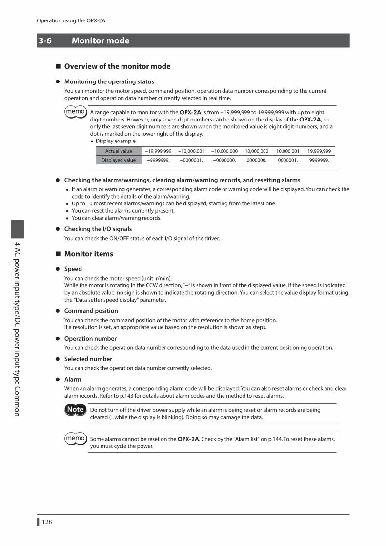
Operation using the OPX-2A
4 AC power input type/D
C power input type Com
mon
128
3-6 Monitor mode
Overview of the monitor mode
z Monitoring the operating statusYou can monitor the motor speed, command position, operation data number correspoinding to the current operation and operation data number currently selected in real time.
A range capable to monitor with the OPX-2A is from −19,999,999 to 19,999,999 with up to eight digit numbers. However, only seven digit numbers can be shown on the display of the OPX-2A, so only the last seven digit numbers are shown when the monitored value is eight digit numbers, and a dot is marked on the lower right of the display.
• Display example
Actual value −19,999,999 −10,000,001 −10,000,000 10,000,000 10,000,001 19,999,999
Displayed value −9999999. −0000001. −0000000. 0000000. 0000001. 9999999.
z Checking the alarms/warnings, clearing alarm/warning records, and resetting alarms • If an alarm or warning generates, a corresponding alarm code or warning code will be displayed. You can check the
code to identify the details of the alarm/warning. • Up to 10 most recent alarms/warnings can be displayed, starting from the latest one. • You can reset the alarms currently present. • You can clear alarm/warning records.
z Checking the I/O signalsYou can check the ON/OFF status of each I/O signal of the driver.
Monitor items
z SpeedYou can check the motor speed (unit: r/min).While the motor is rotating in the CCW direction, “−” is shown in front of the displayed value. If the speed is indicated by an absolute value, no sign is shown to indicate the rotating direction. You can select the value display format using the "Data setter speed display" parameter.
z Command positionYou can check the command position of the motor with reference to the home position.If a resolution is set, an appropriate value based on the resolution is shown as steps.
z Operation numberYou can check the operation data number corresponding to the data used in the current positioning operation.
z Selected numberYou can check the operation data number currently selected.
z AlarmWhen an alarm generates, a corresponding alarm code will be displayed. You can also reset alarms or check and clear alarm records. Refer to p.143 for details about alarm codes and the method to reset alarms.
Do not turn off the driver power supply while an alarm is being reset or alarm records are being cleared (=while the display is blinking). Doing so may damage the data.
Some alarms cannot be reset on the OPX-2A. Check by the "Alarm list" on p.144. To reset these alarms, you must cycle the power.

Operation using the OPX-2A4 AC pow
er input type/DC pow
er input type Comm
on
129
z WariningWhen a warning generates, a corresponding warning code will be displayed. You can also check or clear warning records. For details about warning code, refer to p.150.
Do not turn off the driver power supply while warning records are being cleared (=while the display is blinking). Doing so may damage the data.
You can also clear the warning records by turning off the driver power supply.
z Direct I/O monitorYou can check the ON/OFF status of each I/O signal of the driver.Each digit on the 7-segment LED display corresponds to a signal. The LED is lit when the signal is ON, and it is unlit when the signal is OFF.
• Input signals
IN0IN1
IN2IN3
IN4IN5
IN6IN7
Input signals monitor
+LS-LS
HOMESSLIT
Sensor signals monitor
•Output signals
OUT0OUT1
OUT2OUT3
OUT4OUT5
Output signals monitor
3-7 Data mode
Up to 64 sets of motor operation data can be set. Once set, the operation data is saved in the non-volatile memory of the driver. The data will not be lost even after the OPX-2A is disconnected from the driver.
Operation data has significant bearing on motor operation. Before setting any operation data, make sure you fully understand the content of the operation data.
• If the operations are limited by the edit lock function or HMI input, operation data cannot be edited.
• Operation data can also be set by selecting the ID with the parameter mode. • If the value you have input is outside the setting range, "Error" will be displayed for 1 second. If this error display appears, input a different value that falls within the setting range.
• If key is pressed while executing the internal processing via RS-485 communication, "mEm-bUSy" may be displayed. Check "3-5 Screen transitions" on p.124 when "mEm-bUSy" is displayed. Be sure to wait until all internal processing is completed, before pressing the key.

Operation using the OPX-2A
4 AC power input type/D
C power input type Com
mon
130
Setting item
Setting item Description Initial value
Operation mode
Selects how to specify the position (travel amount) in positioning operation.
[Setting range] 0: Incremental 1: Absolute
0
PositionSets the position (distance) for positioning operation.
[Setting range] −8,388,608 to +8,388,607 step
0
Operating speedSets the operating speed in positioning operation and continuous operation.
[Setting range] 1 to 1,000,000 Hz
1,000
Operation function
Sets the operation mode to execute positioning operation.
[Setting range] 0: Single-motion 1: Linked-motion 2: Linked-motion 2 3: Push
0
Sequential positioning
Sets whether to enable or disable sequential positioning operation.
[Setting range] 0: Disable 1: Enable
0
Acceleration *
Sets the acceleration rate (acceleration time) in positioning operation and continuous operation.
[Setting range] 0.001 to 1,000.000 ms/kHz or 0.001 to 1,000.000 s
1.000
Deceleration *
Sets the deceleration rate (deceleration time) in positioning operation and continuous operation.
[Setting range] 0.001 to 1,000.000 ms/kHz or 0.001 to 1,000.000 s
Push currentSets the current rate of push-motion operation.
[Setting range] 0.0 to 100.0%
20.0
Dwell timeSets the dwell time to be used in linked-motion 2 operation.
[Setting range] 0.000 to 50.000 s
0.000
* This item is effective when the "Acceleration/deceleration type" parameteris set to "separate." If this parameter is set to "common", the values of the "Common acceleration" and "Common deceleration" parameters will be used.
z How to set the dwell timeWhen displaying the "2: Linked-motion 2" on the "Operation function" and pressing the key, the screen to set the dwell time is displayed. Input the dwell time using the keys and press the key.
Dwell timeProcessing is in progress (blinking)
Single-motion
Linked-motion
Linked-motion 2
Push
Operation function

Operation using the OPX-2A4 AC pow
er input type/DC pow
er input type Comm
on
131
Setting exampleThis section explains how to change the the operation mode and position of the operation data No.0.
• Operation mode: Changes from incremental to absolute. • Position: Changes from 0 step to 10,000 steps.
1. Use the key to select the data mode.The "DATA" LED is lit.
Operation mode
Input 10,000 (blinking)
Present value (blinking)
Change to absolute mode (blinking)
Conrm the changed value (quick blinking)
Return to the operation mode
Position
Present value (blinking)
Operation data No.0
Top screen of the data mode
Use to increase/decrease the value.
Use to navigatethrough the digits.
Conrm the changed value (quick blinking)
Return to the position
Return to the operation data No.0
2. Press the key on the top screen of the data mode.The display changes to the operation data No.0 screen.
3. Press the key.The display changes to the operation mode screen.
4. Press the key again.The present set value of the operation mode is displayed with blinking.
5. Press the key once to select "1."
6. Press the key.The blinking speed of the input value becomes quickly and the value is set. The display returns to the operation mode screen.
7. Press the key.The display changes to the position screen.
8. Press the key.The present set value of the position is displayed with blinking.
9. Use the keys to select "10,000."The selected digit is displayed with blinking.
10. Press the key.The blinking speed of the input value becomes quickly and the value is set. The display returns to the position screen.
11. Press the key.The display returns to the operation data No.0 screen.
Initialization of the selected operation dataAll of the set value for the selected operation data number can be reverted to the initial values. Perform "clear data" of the data mode. For the operation, check the screen transitions of the data mode on p.125.
Initialization of all operation dataAll of the operation data saved in the driver can be reverted to the initial values. Perform "Initialize operation data" of the copy mode. For the operation, check the screen transitions of the copy mode on p.127.

Operation using the OPX-2A
4 AC power input type/D
C power input type Com
mon
132
3-8 Parameter mode
You can set parameters relating to motor operation and control. These parameters are saved in the non-volatile memory of the driver.
Parameters have significant bearing on motor operation. Before setting any parameter, make sure you fully understand the content of the parameter.
• If operations are limited by the edit lock function or HMI input, parameters cannot be edited. • If the value you have input is outside the setting range, "Error" will be displayed for 1 second. If this error display appears, input a different value that falls within the setting range.
• If key is pressed while executing the internal processing via RS-485 communication, "mEm-bUSy" may be displayed. Check "3-5 Screen transitions" on p.124 when "mEm-bUSy" is displayed. Be sure to wait until all internal processing is completed, before pressing the key.
• If a nonexistent parameter ID is entered, "id-Err" will be displayed for 1 second. Check the ID and enter the correct one.
z Timing to update the setting valueWhen a parameter is changed, the timing to update the new value varies depending on the parameter. See the following three types.
Update timing Description
A ImmediatelyExecutes the recalculation and setup immediately when writing the parameter.
B After stopping the operation Executes the recalculation and setup after stopping the operation.
C After cycle the power Executes the recalculation and setup after cycling the DC power supply.
In this chapter, each update timing is represented in A to C.
Setting exampleThis section explains how to assign the TIM output to the OUT1 output.
1. Use the key to select the parameter mode.The "PAR" LED is lit.
Return to the “OUT1 output function selection” parameter
Present value (blinking)
Set the OUT1 output to “72” (blinking)
Conrm the value (quick blinking)
Select parameter
“OUT1 output function selection” parameter
Top screen of the parameter mode
Use to increase/decrease the value.
Use to navigatethrough the digits.
Use to increase/decrease the value.
Use to navigatethrough the digits.
2. Press the key on the top screen of the parameter mode.
3. Use the keys to enter [ID: 2209] in the "OUT1 output function selection" parameter.
4. Press the key.The present set value of the "OUT1 output function selection" parameter is displayed with blinking.
5. Use the keys to enter "72.""72" indicates the TIM output.
6. Press the key.The blinking speed of the input value becomes quickly and the value is set.The display returns to the "OUT1 output function selection" parameter screen.

Operation using the OPX-2A4 AC pow
er input type/DC pow
er input type Comm
on
133
Parameter listThere is an unique ID in each parameter. With the OPX-2A, set the parameter selecting the ID.
z Operation dataOperation data can also be set by selecting the data mode.
ID Parameter name Setting range Initila value Update (p.132)
640 to
703
Operation mode No.0 to
Operation mode No.63
0: Incremental 1: Absolute
0
B
512 to
575
Position No.0 to
Position No.63−8,388,608 to +8,388,607 step 0
576 to
639
Operating speed No.0 to
Operating speed No.630 to 1,000,000 Hz 1,000
704 to
767
Operation function No.0 to
Operation function No.63
0: Single-motion 1: Linked-motion 2: Linked-motion 2 3: Push
0
960 to
1023
Sequencial positioning No.0 to
Sequencial positioning No.63
0: Disable 1: Enable
0
768 to
831
Acceleration No.0 * to
Acceleration No.63 *
0.001 to 1,000.000 ms/kHz or 0.001 to 1,000.000 s
1.000
832 to
895
Deceleration No.0 * to
Deceleration No.63 *
0.001 to 1,000.000 ms/kHz or 0.001 to 1,000.000 s
1.000
896 to
959
Push current No.0 to
Push current No.630.0 to 100.0% 20.0
1024 to
1087
Dwell time No.0 to
Dwell time No.630.000 to 50.000 s 0.000
* This item is effective when the "Acceleration/deceleration type" parameteris set to "separate." If this parameter is set to "common", the values of the "Common acceleration" and "Common deceleration" parameters will be used.
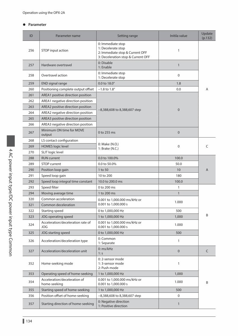
Operation using the OPX-2A
4 AC power input type/D
C power input type Com
mon
134
z Parameter
ID Parameter name Setting range Initila valueUpdate (p.132)
256 STOP input action
0: Immediate stop 1: Decelerate stop 2: Immediate stop & Current OFF 3: Deceleration stop & Current OFF
1
A
257 Hardware overtravel0: Disable 1: Enable
1
258 Overtravel action0: Immediate stop 1: Decelerate stop
0
259 END signal range 0.0 to 18.0° 1.8
260 Positioning complete output offset −1.8 to 1.8° 0.0
261 AREA1 positive direction position
−8,388,608 to 8,388,607 step 0
262 AREA1 negative direction position
263 AREA2 positive direction position
264 AREA2 negative direction position
265 AREA3 positive direction position
266 AREA3 negative direction position
267Minimum ON time for MOVE output
0 to 255 ms 0
268 LS contact configuration0: Make (N.O.) 1: Brake (N.C.)
0 C269 HOMES logic level
270 SLIT logic level
288 RUN current 0.0 to 100.0% 100.0
A
289 STOP current 0.0 to 50.0% 50.0
290 Position loop gain 1 to 50 10
291 Speed loop gain 10 to 200 180
292 Speed loop integral time constant 10.0 to 200.0 ms 100.0
293 Speed filter 0 to 200 ms 1
B
294 Moving average time 1 to 200 ms 1
320 Common acceleration 0.001 to 1,000.000 ms/kHz or 0.001 to 1,000.000 s
1.000321 Common deceleration
322 Starting speed 0 to 1,000,000 Hz 500
323 JOG operating speed 1 to 1,000,000 Hz 1,000
324Acceleration/deceleration rate of JOG
0.001 to 1,000.000 ms/kHz or 0.001 to 1,000.000 s
1.000
325 JOG starting speed 0 to 1,000,000 Hz 500
326 Acceleration/deceleration type0: Common 1: Separate
1
327 Acceleration/deceleration unit0: ms/kHz 1: s
0 C
352 Home-seeking mode0: 2-sensor mode 1: 3-sensor mode 2: Push mode
1
B
353 Operating speed of home-seeking 1 to 1,000,000 Hz 1,000
354Acceleration/deceleration of home-seeking
0.001 to 1,000.000 ms/kHz or 0.001 to 1,000.000 s
1.000
355 Starting speed of home-seeking 1 to 1,000,000 Hz 500
356 Position offset of home-seeking −8,388,608 to 8,388,607 step 0
357 Starting direction of home-seeking0: Negative direction 1: Positive direction
1

Operation using the OPX-2A4 AC pow
er input type/DC pow
er input type Comm
on
135
ID Parameter name Setting range Initila valueUpdate (p.132)
358 SLIT detection with home-seeking0: Disable 1: Enable
0B
359TIM signal detection with home-seeking
360Operating current of home-seeking with push-motion
0.0 to 100.0% 100.0
384 Overload alarm 0.1 to 30.0 s 5.0A
385Excessive position deviation alarm at current ON
0.01 to 300.00 rev 3.00
388 Return-to-home incomplete alarm0: Disable 1: Enable
0 C
416 Overheat warning 40 to 85 °C 85
A
417 Overload warning 0.1 to 30.0 s 5.0
418 Overspeed warning 1 to 5,000 r/min 4,500
419 Overvoltage warningAC power input: 120 to 450 V DC power input: 150 to 630 (1=0.1 V)
AC power input: 435 DC power input: 630
420 Undervoltage warningAC power input: 120 to 280 V DC power input: 150 to 630 (1=0.1 V)
AC power input: 120 DC power input: 180
421Excessive position deviation warning at current ON
0.01 to 300.00 rev 3.00
448 Electronic gear A1 to 65,535 1
C449 Electronic gear B
450 Motor rotation direction0: Positive direction=CCW 1: Positive direction=CW
1
451 Software overtravel0: Disabel 1: Enable
1
A452 Positive software limit
−8,388,608 to 8,388,607 step
8,388,607
453 Negative software limit −8,388,608
454 Preset position 0
455 Wrap setting0: Disable 1: Enable
0C
456 Wrap setting range 1 to 8,388,607 step 1,000
480 Data setter speed display0: Signed 1: Absolute value
0 A
482 Absolute back-up system0: Disable 1: Enable
0 C
2048 MS0 operation No. selection
0 to 63
0
B
2049 MS1 operation No. selection 1
2050 MS2 operation No. selection 2
2051 MS3 operation No. selection 3
2052 MS4 operation No. selection 4
2053 MS5 operation No. selection 5
2054 HOME-P output function selection0: Home output 1: Return-to-home complete output
0 A
2064 Filter selection0: Speed filter 1: Moving average filter
0 C
2065 Speed difference gain 10 to 500 45 A
2066 Speed difference gain 2
2067 Control mode0: Normal mode 1: Current control mode
0 C
2068 Smooth drive 0: Disable 1: Enable
1C
2080 Automatic return operation 0

Operation using the OPX-2A
4 AC power input type/D
C power input type Com
mon
136
ID Parameter name Setting range Initila valueUpdate (p.132)
2081Operation speed of automatic return
1 to 1,000,000 Hz 1,000
B2082Acceleration (deceleration) of automatic return
0.001 to 1,000.000 ms/kHz or 0.001 to 1,000.000 s
1.000
2083 Starting speed of automatic return 0 to 1,000,000 Hz 500
2084 JOG travel amount 1 to 8,388,607 step 1
2112Excessive position deviation alarm at current OFF
0.01 to 300.00 rev 100.00 A
2176 IN0 input function selection
Refer to "IN input function selection" on p.138.
3: HOME
C
2177 IN1 input function selection 4: START
2178 IN2 input function selection 48: M0
2179 IN3 input function selection 49: M1
2180 IN4 input function selection 50: M2
2181 IN5 input function selection 16: FREE
2182 IN6 input function selection 18: STOP
2183 IN7 input function selection 24: ALM-RST
2192 IN0 input logic level setting
0: Make (N.O.) 1: Brake (N.C.)
0
2193 IN1 input logic level setting
2194 IN2 input logic level setting
2195 IN3 input logic level setting
2196 IN4 input logic level setting
2197 IN5 input logic level setting
2198 IN6 input logic level setting
2199 IN7 input logic level setting
2208 OUT0 output function selection
Refer to "OUT output function selection" on p.138.
70: HOME-P
2209 OUT1 output function selection 69: END
2210 OUT2 output function selection 73: AREA1
2211 OUT3 output function selection 67: READY
2212 OUT4 output function selection 66: WNG
2213 OUT5 output function selection 65: ALM
2224 NET-IN0 input function selection
Refer to "NET-IN input function selection" on p.138.
48: M0
C
2225 NET-IN1 input function selection 49: M1
2226 NET-IN2 input function selection 50: M2
2227 NET-IN3 input function selection 4: START
2228 NET-IN4 input function selection 3: HOME
2229 NET-IN5 input function selection 18: STOP
2230 NET-IN6 input function selection 16: FREE
2231 NET-IN7 input function selection 0: No function
2232 NET-IN8 input function selection 8: MS0
2233 NET-IN9 input function selection 9: MS1
2234 NET-IN10 input function selection 10: MS2
2235 NET-IN11 input function selection 5: SSTART
2236 NET-IN12 input function selection 6: +JOG
2237 NET-IN13 input function selection 7: −JOG
2238 NET-IN14 input function selection 1: FWD
2239 NET-IN15 input function selection 2: RVS
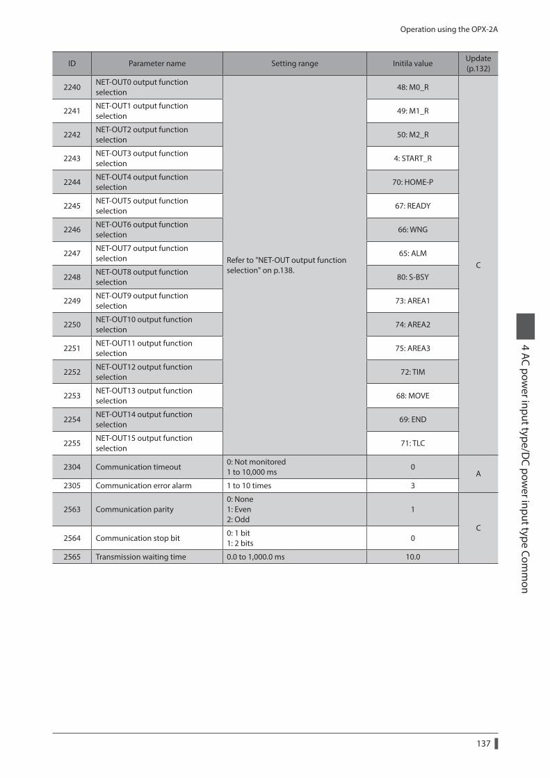
Operation using the OPX-2A4 AC pow
er input type/DC pow
er input type Comm
on
137
ID Parameter name Setting range Initila valueUpdate (p.132)
2240NET-OUT0 output function selection
Refer to "NET-OUT output function selection" on p.138.
48: M0_R
C
2241NET-OUT1 output function selection
49: M1_R
2242NET-OUT2 output function selection
50: M2_R
2243NET-OUT3 output function selection
4: START_R
2244NET-OUT4 output function selection
70: HOME-P
2245NET-OUT5 output function selection
67: READY
2246NET-OUT6 output function selection
66: WNG
2247NET-OUT7 output function selection
65: ALM
2248NET-OUT8 output function selection
80: S-BSY
2249NET-OUT9 output function selection
73: AREA1
2250NET-OUT10 output function selection
74: AREA2
2251NET-OUT11 output function selection
75: AREA3
2252NET-OUT12 output function selection
72: TIM
2253NET-OUT13 output function selection
68: MOVE
2254NET-OUT14 output function selection
69: END
2255NET-OUT15 output function selection
71: TLC
2304 Communication timeout0: Not monitored 1 to 10,000 ms
0A
2305 Communication error alarm 1 to 10 times 3
2563 Communication parity0: None 1: Even 2: Odd
1
C2564 Communication stop bit
0: 1 bit 1: 2 bits
0
2565 Transmission waiting time 0.0 to 1,000.0 ms 10.0

Operation using the OPX-2A
4 AC power input type/D
C power input type Com
mon
138
z Setting range for function selection parameters
IN input function selection
0: No function 1: FWD 2: RVS 3: HOME 4: START 5: SSTART 6: +JOG 7: −JOG
8: MS0 9: MS1 10: MS2 11: MS3 12: MS4 13: MS5 16: FREE 17: C-ON
18: STOP 24: ALM-RST 25: P-PRESET 26: P-CLR 27: HMI 32: R0 33: R1 34: R2
35: R3 36: R4 37: R5 38: R6 39: R7 40: R8 41: R9 42: R10
43: R11 44: R12 45: R13 46: R14 47: R15 48: M0 49: M1 50: M2
51: M3 52: M4 53: M5
OUT output function selection
0: No function 1: FWD_R 2: RVS_R 3: HOME_R 4: START_R 5: SSTART_R 6: +JOG_R 7: −JOG_R 8: MS0_R 9: MS1_R
10: MS2_R 11: MS3_R 12: MS4_R 13: MS5_R 16: FREE_R 17: C-ON_R 18: STOP_R 32: R0 33: R1 34: R2
35: R3 36: R4 37: R5 38: R6 39: R7 40: R8 41: R9 42: R10 43: R11 44: R12
45: R13 46: R14 47: R15 48: M0_R 49: M1_R 50: M2_R 51: M3_R 52: M4_R 53: M5_R 60: +LS_R
61: −LS_R 62: HOMES_R 63: SLIT_R 65: ALM 66: WNG 67: READY 68: MOVE 69: END 70: HOME-P 71: TLC
72: TIM 73: AREA1 74: AREA2 75: AREA3 80: S-BSY 82: MPS *
* AC power input only.
NET-IN input function selection
0: No function 1: FWD 2: RVS 3: HOME 4: START 5: SSTART 6: +JOG 7: −JOG
8: MS0 9: MS1 10: MS2 11: MS3 12: MS4 13: MS5 16: FREE 17: C-ON
18: STOP 24: ALM-RST * 25: P-PRESET * 26: P-CLR * 27: HMI 32: R0 33: R1 34: R2
35: R3 36: R4 37: R5 38: R6 39: R7 40: R8 41: R9 42: R10
43: R11 44: R12 45: R13 46: R14 47: R15 48: M0 49: M1 50: M2
51: M3 52: M4 53: M5
* It cannot be set in the driver that is before the specification change. Refer to p.7 for details.
NET-OUT output function selection
0: No function 1: FWD_R 2: RVS_R 3: HOME_R 4: START_R 5: SSTART_R 6: +JOG_R 7: −JOG_R 8: MS0_R 9: MS1_R
10: MS2_R 11: MS3_R 12: MS4_R 13: MS5_R 16: FREE_R 17: C-ON_R 18: STOP_R 32: R0 33: R1 34: R2
35: R3 36: R4 37: R5 38: R6 39: R7 40: R8 41: R9 42: R10 43: R11 44: R12
45: R13 46: R14 47: R15 48: M0_R 49: M1_R 50: M2_R 51: M3_R 52: M4_R 53: M5_R 60: +LS_R
61: −LS_R 62: HOMES_R 63: SLIT_R 65: ALM 66: WNG 67: READY 68: MOVE 69: END 70: HOME-P 71: TLC
72: TIM 73: AREA1 74: AREA2 75: AREA3 80: S-BSY 82: MPS *
* AC power input only.

Operation using the OPX-2A4 AC pow
er input type/DC pow
er input type Comm
on
139
3-9 Test mode
Overview of the test mode
z Direct I/O testYou can check the ON/OFF status of each input signal of the driver. You can also switch the ON/OFF status of each output signal on the OPX-2A. When checking the connection condition of the driver, perform the direct I/O test.
z JOG operationYou can operate the motor using the keys on the OPX-2A.
z Data select operationYou can perform the positioning operation.
z Return-to-home operationYou can perform the return-to-home operation.
z Position presetYou can set the preset value as the command position.
z TeachingYou can operate the motor using the keys on the OPX-2A and update the attained position in the operation data.
• Stop the motor operation before changing to the test mode. • When you move from the top screen of the test mode to a lower level, the following inputs will be disabled. START, SSTART, HOME, ±JOG, FWD, RVS and MS0 to MS5.
• In the direct I/O test, if the screen moves to the lower level, all of I/O signals and operation will be disabled.
• If the key is pressed while executing the internal processing via RS-485 communication, "mEm-bUSy" may be displayed. Check "3-5 Screen transitions" on p.124 when "mEm-bUSy" is displayed. Be sure to wait until all internal processing is completed, before pressing the key.
• If "Error" is displayed when data select operation, return-to-home operation, position preset or teaching function is performed, check whether an alarm generates.
• When the HMI input is OFF, test mode cannot be executed.
z What happens when the key is pressed while the motor is operatingWhile the motor is operating, you cannot move to any lower level from the top screen of the test mode. Pressing the key will generate an error, and "oPE-Err" will be shown. Be sure to stop the motor operation before pressing the key.
Direct I/O testWhen checking the connection condition of the driver, perform the direct I/O test.Each digit on the 7-segment LED display corresponds to a signal. The LED is lit when the input signal is ON, and it is unlit when the input signal is OFF.Use the keys to switch the ON-OFF state of the output signal. " " is displayed when the signal is ON, while " " is displayed when the signal is OFF.
z Input signals
IN0IN1
IN2IN3IN4
IN5IN6
IN7
Input signals test
+LS-LS
HOMESSLIT
Sensor signals test
z Output signals
OUT0OUT1
OUT3 OUT2
OUT5OUT4
indicates the OFF status.
indicates the ON status.
Output signals test
Use to switch the ON/OFF status.
Use to navigate through the digits.

Operation using the OPX-2A
4 AC power input type/D
C power input type Com
mon
140
JOG operationYou can operate the motor using the keys on the OPX-2A.Pressing the key once causes the motor to rotate one step in the positive direction. Pressing and holding the key causes the motor to rotate continuously in the positive direction.Pressing the key once causes the motor to rotate one step in the negative direction. Pressing and holding the key causes the motor to rotate continuously in the negative direction.
The operating speed corresponds to the value set in the "JOG operating speed" parameter.Take note that when the value set in the "JOG starting speed" parameter is greater than the value set in the "JOG operating speed" parameter, the JOG starting speed will become effective.
1 s than less 1 s or more
VS
Speed
Time
VRTR TR
1step 1step
key
VS: JOG starting speedVR: JOG operating speedTR: Acceleration/deceleration rate of JOG
During operation, the motor rotates at the specified operating speed while each applicable key is pressed. Before commencing the operation, consider the status of the equipment and condition of its surroundings to confirm thoroughly that motor rotation will not cause any dangerous situations.
Data select operationSelect a desired operation data number and then press the key, and positioning operation will be performed.
During operation, the motor rotates at the specified operating speed. Before commencing the operation, consider the status of the equipment and condition of its surroundings to confirm thoroughly that motor rotation will not cause any dangerous situations.
Return-to-home operationYou can perform a return-to-home operation. The operating speed corresponds to the value set in the "Operating speed of home-seeking" parameter.
During operation, the motor rotates at the specified operating speed. Before commencing the operation, consider the status of the equipment and condition of its surroundings to confirm thoroughly that motor rotation will not cause any dangerous situations.
Presetting the positionIn this operation, the command position is preset by rewriting the value in the "Preset position" parameter.
If operations are limited by the edit lock function, the preset cannot be performed.
TeachingYou can operate the motor using the keys on the OPX-2A and update the attained position in the operation data. The absolute mode will be automatically selected as the operation mode of any position data set by teaching.The operating speed, acceleration/deceleration rate and starting speed of teaching are the same as the corresponding settings applicable to JOG operation.
During operation, the motor rotates at the specified operating speed. Before commencing the operation, consider the status of the equipment and condition of its surroundings to confirm thoroughly that motor rotation will not cause any dangerous situations.
If operations are limited by the edit lock function, the teaching cannot be performed.

Operation using the OPX-2A4 AC pow
er input type/DC pow
er input type Comm
on
141
3-10 Copy mode
Overview of the copy mode
z DownloadData saved in the OPX-2A can be copied to the driver. If a download error occurs, a code indicating the description of the error will blink on the display. Download will not be performed and the display will return to the top screen of download. Refer to the following "Error of the copy mode" to display the error.
z UploadData saved in the driver can be copied to the OPX-2A.
Driver
Upload driver datato the OPX-2A.
Download OPX-2A data to the driver.
z VerificationData in the OPX-2A can be verified against the corresponding data in the driver.If the verification finds that the two sets of data match, “Good” will be shown. If the two do not match, “Error” will be shown.If a verification error occurs, a code indicating the description of the error will blink on the display. Verification will not be performed and the display will return to the top screen of verification. Refer to the following "Error of the copy mode" to display the error.
z Initializing dataData saved in the driver can be restored to the initial values.
z What happens when the key is pressed while the edit lock function is enabledWhile the edit lock function is enabled, you cannot move to any lower level from the top screen of the copy mode. Pressing the key will generate an error, and “LocK-Err” will be shown. Be sure to cancel the edit lock function before pressing the
key. Refer to p.121 for the procedure to cancel the edit lock function.
Error of the copy modeIf an error occurs in download or verification, the error code will blink on the display.At this time, the processing will not be executed and the display will return to the top screen.
Blinking display Description Action
There is a discrepancy between the selected product series and the data being processed.
•Check the product series.
•Check the data bank number on the OPX-2A.
An error occurred while processing.
Execute the processing again. If the same error occurs, the data saved in the OPX-2A may have damaged. Upload and set the data of the OPX-2A again.
The specified data bank number does not contain data.
Check the data bank number.
Do not turn off the driver power supply while processing is in progress (=while the display is blinking). Doing so may damage the data.
When a parameter that the power supply is required to turn on again for updating was changed by downloading, turn on the DC power supply of the driver again.
Inspection and maintenance
4 AC power input type/D
C power input type Com
mon
142
4 Inspection and maintenance
4-1 Inspection
It is recommended that periodic inspections be conducted for the items listed below after each operation of the motor. If an abnormal condition is noted, discontinue any use and contact your nearest Oriental Motor sales office.
During inspection • Check if any of the screws having installed the motor comes loose. • Check if an unusual noise is generated from a bearing part (ball bearings) of the motor. • Check if a damage or stress is applied on the motor cable. Check if the connection part between the motor and
driver comes loose. • Check if the motor output shaft and the load shaft are out of alignment. • Check if the openings in the driver blocked. • Check if the connection part with the connector or the driver comes loose. • Check if any attachment of dust, etc., on the driver. • Check if any strange smells or appearances within the driver.
The driver uses semiconductor elements. Handle the driver with care since static electricity may damage semiconductor elements.
4-2 Warranty
Check on the Oriental Motor Website or General Catalog for the product warranty.
4-3 Disposal
Dispose the product correctly in accordance with laws and regulations, or instructions of local governments.

Alarms and warnings4 AC pow
er input type/DC pow
er input type Comm
on
143
5 Alarms and warnings
The driver provides alarms that are designed to protect the driver from overheating, poor connection, error in operation, etc. (protective functions), as well as warnings that are output before the corresponding alarms generate (warning functions).
5-1 Alarms
When an alarm generates, the ALM output will turn OFF and the motor will stop. At the same time, the ALM LED (or ALARM LED) will start blinking.The present alarm can be checked by counting the number of times the LED blinks, or using the MEXE02, OPX-2A or via RS-485 communication.
Example: Hardware overtravel alarm [number of times the ALM LED (or ALARM LED) blinks: 7]
Approximately 200 ms
Approximately1.4 s
Approximately 200 ms
Interval
Alarm resetPerform one of the reset operations specified below. Before resetting an alarm, always remove the cause of the alarm and ensure safety. Refer to p.311 for the timing chart.
• Turn the ALM-RST input from ON to OFF. (The alarm will be reset at the OFF edge of the input.) • Perform the alarm reset via RS-485 communication. • Perform the alarm reset using the MEXE02 or OPX-2A. • Cycle the power.
The absolute position error alarm can be reset by turning the P-CLR input from ON to OFF, or executing the reset of the absolute position error alarm using the MEXE02, OPX-2A or via RS-485 communication. This alarm cannot be reset by any other methods.
Alarm recordsUp to 10 generated alarms are saved in the non-volatile memory in order of the latest to oldest.Alarm records saved in the non-volatile memory can be read and cleared when performing any of the following.
• Read the alarm records by the monitor command via RS-485 communication. • Clear the alarm records by the maintenance command via RS-485 communication. • Read and clear the alarm records using the MEXE02 or OPX-2A.

Alarms and warnings
4 AC power input type/D
C power input type Com
mon
144
Alarm list
CodeNumber of times the ALARM LED
blinksAlarm type Cause Remedial action Alarm reset
Motor excitation *1
10h
4
Excessive position deviation
•When the motor was in a state of current on, the deviation between the command position and actual position exceeded the "Excessive position deviation alarm at current ON" parameter.
• The load is large, or the acceleration/deceleration is too short.
• Reduce the load or increase the acceleration/deceleration.
• If the driver is in the current control mode, increase the current limit value. • Turn the ALM-RST input from ON (1)
to OFF (0).
• Perform alarm reset.
Excitation off
12hExcessive position deviation during current OFF
The C-ON input was turned ON while an excessive position deviation warning during current OFF was present.
•Do not turn the C-ON input ON while an excessive position deviation warning at current OFF is present.
• Set the "Automatic return operation" prameter to “disable.”
20h 5 Overcurrent *2The motor, cable and driver output circuit were short-circuited.
Turn off the power supply, and check that the motor, cable and driver output circuit are not short-circuited before turning on the power again.
Cycle the power.
21h 2 Main circuit overheatThe internal temperature of the driver exceeded 85 °C (185 °F).
Review the ventilation condition inside the enclosure. • Turn the ALM-RST input from ON (1) to OFF (0).
• Perform alarm reset.
22h
3
Overvoltage •A voltage exceeding the specification value was applied.
•A large inertial load was stopped abruptly or vertical operation was performed.
•Check the input voltage of the power supply.
• If this alarm generates during operation, reduce the load or increase the acceleration/deceleration.
•Cycle the power.
• Perform alarm reset (DC power input only).
23h Main power off *2The motor was started when the main power supply had been cut off.
Check if the main power supply has been input normally. • Turn the ALM-RST input from ON (1) to OFF (0).
• Perform alarm reset.25h Undervoltage
The main power was cut off momentarily or the voltage became low.
Check the input voltage of the main power supply.
27h 7 Backup battery undervoltage The battery voltage became below the rated value. Charge the battery. Excitation on
28h 8 Sensor error A sensor error occurred while the motor was operating.Turn off the power, and turn on the power again after checking the connection for the motor cable and driver.
Cycle the power.
Excitation off
29h 9 CPU peripheral circuit error An error occurred in the CPU.
• If a battery is used, turn off the power before disconnecting it. After that, connect the battery again, and turn on the power. Check an alarm does not generate, and be sure to perform return-to-home operation.
• If a battery is not used, turn on the power again. After that, check an alarm does not generate, and be sure to perform return-to-home operation.
2Dh 5 Main circuit output error *2 The motor cable was disconnected.Turn off the power, and turn on the power again after checking the connection for the motor cable and driver.
30h
2
OverloadA load exceeding the peak torque was applied for the time exceeded the "Overload alarm" parameter.
• Reduce the load or increase the acceleration/deceleration.
• If the driver is in the current control mode, increase the current limit value.
•Check the connection of the driver and electromagnetic brake. • Turn the ALM-RST input from ON (1) to OFF (0).
• Perform alarm reset.
31h OverspeedThe rotation speed of the motor output shaft exceeded 4,500 r/min.
•Check the "Electronic gear" parameter and set the speed of the motor output shaft to 4,500 r/min or less.
• If the motor is overshooting at the time of acceleration, increase the acceleration.
33h 7 Absolute position error
While the "Absolute back-up system" parameter was "enable," one of the following conditions is satisfied.
• The power was turned on while the position origin was not set.
• The power was turned on while the battery was not connected.
• The power was turned on while operation range of multi-rotation was exceeded the specification.
• Execute P-PRESET or return-to-home operation after inputting the P-CLR.
•Check the connection of the battery. Or replace the battery.
• Turn the P-CLR input from ON (1) to OFF (0).
• Perform the reset of the absolute position error alarm.
Excitation on
Sudden load fluctuations occurred when the position was managed with the battery.
Do not apply sudden load fluctuations.

Alarms and warnings4 AC pow
er input type/DC pow
er input type Comm
on
145
Alarm list
CodeNumber of times the ALARM LED
blinksAlarm type Cause Remedial action Alarm reset
Motor excitation *1
10h
4
Excessive position deviation
•When the motor was in a state of current on, the deviation between the command position and actual position exceeded the "Excessive position deviation alarm at current ON" parameter.
• The load is large, or the acceleration/deceleration is too short.
• Reduce the load or increase the acceleration/deceleration.
• If the driver is in the current control mode, increase the current limit value. • Turn the ALM-RST input from ON (1)
to OFF (0).
• Perform alarm reset.
Excitation off
12hExcessive position deviation during current OFF
The C-ON input was turned ON while an excessive position deviation warning during current OFF was present.
•Do not turn the C-ON input ON while an excessive position deviation warning at current OFF is present.
• Set the "Automatic return operation" prameter to “disable.”
20h 5 Overcurrent *2The motor, cable and driver output circuit were short-circuited.
Turn off the power supply, and check that the motor, cable and driver output circuit are not short-circuited before turning on the power again.
Cycle the power.
21h 2 Main circuit overheatThe internal temperature of the driver exceeded 85 °C (185 °F).
Review the ventilation condition inside the enclosure. • Turn the ALM-RST input from ON (1) to OFF (0).
• Perform alarm reset.
22h
3
Overvoltage •A voltage exceeding the specification value was applied.
•A large inertial load was stopped abruptly or vertical operation was performed.
•Check the input voltage of the power supply.
• If this alarm generates during operation, reduce the load or increase the acceleration/deceleration.
•Cycle the power.
• Perform alarm reset (DC power input only).
23h Main power off *2The motor was started when the main power supply had been cut off.
Check if the main power supply has been input normally. • Turn the ALM-RST input from ON (1) to OFF (0).
• Perform alarm reset.25h Undervoltage
The main power was cut off momentarily or the voltage became low.
Check the input voltage of the main power supply.
27h 7 Backup battery undervoltage The battery voltage became below the rated value. Charge the battery. Excitation on
28h 8 Sensor error A sensor error occurred while the motor was operating.Turn off the power, and turn on the power again after checking the connection for the motor cable and driver.
Cycle the power.
Excitation off
29h 9 CPU peripheral circuit error An error occurred in the CPU.
• If a battery is used, turn off the power before disconnecting it. After that, connect the battery again, and turn on the power. Check an alarm does not generate, and be sure to perform return-to-home operation.
• If a battery is not used, turn on the power again. After that, check an alarm does not generate, and be sure to perform return-to-home operation.
2Dh 5 Main circuit output error *2 The motor cable was disconnected.Turn off the power, and turn on the power again after checking the connection for the motor cable and driver.
30h
2
OverloadA load exceeding the peak torque was applied for the time exceeded the "Overload alarm" parameter.
• Reduce the load or increase the acceleration/deceleration.
• If the driver is in the current control mode, increase the current limit value.
•Check the connection of the driver and electromagnetic brake. • Turn the ALM-RST input from ON (1) to OFF (0).
• Perform alarm reset.
31h OverspeedThe rotation speed of the motor output shaft exceeded 4,500 r/min.
•Check the "Electronic gear" parameter and set the speed of the motor output shaft to 4,500 r/min or less.
• If the motor is overshooting at the time of acceleration, increase the acceleration.
33h 7 Absolute position error
While the "Absolute back-up system" parameter was "enable," one of the following conditions is satisfied.
• The power was turned on while the position origin was not set.
• The power was turned on while the battery was not connected.
• The power was turned on while operation range of multi-rotation was exceeded the specification.
• Execute P-PRESET or return-to-home operation after inputting the P-CLR.
•Check the connection of the battery. Or replace the battery.
• Turn the P-CLR input from ON (1) to OFF (0).
• Perform the reset of the absolute position error alarm.
Excitation on
Sudden load fluctuations occurred when the position was managed with the battery.
Do not apply sudden load fluctuations.
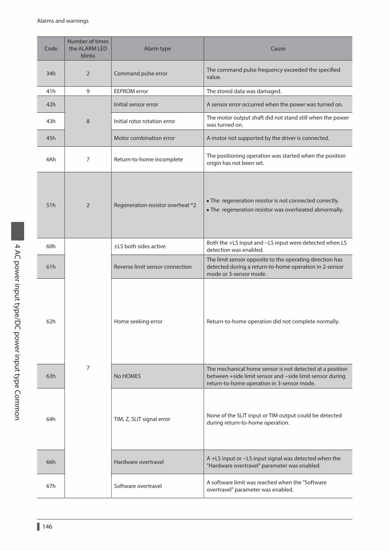
Alarms and warnings
4 AC power input type/D
C power input type Com
mon
146
CodeNumber of times the ALARM LED
blinksAlarm type Cause Remedial action Alarm reset
Motor excitation *1
34h 2 Command pulse errorThe command pulse frequency exceeded the specified value.
Check the “Electronic gear” parameter and reduce the speed of the motor output shaft to 4,500 r/min or less.
• Turn the ALM-RST input from ON (1) to OFF (0).
• Perform alarm reset.
Excitation off
41h 9 EEPROM error The stored data was damaged. Initialize the all parameters.
Cycle the power.
42h
8
Initial sensor error A sensor error occurred when the power was turned on.Turn off the power supply, and check the connection of the motor cable and driver before turning on the power again.
43h Initial rotor rotation errorThe motor output shaft did not stand still when the power was turned on.
Make sure the motor output shaft does not turn by an external force when the power is turned on.
45h Motor combination error A motor not supported by the driver is connected.Check the model name of motor and driver, and use the motor and driver in the correct combination.
4Ah 7 Return-to-home incompleteThe positioning operation was started when the position origin has not been set.
Perform the position preset or return-to-home operation. • Turn the ALM-RST input from ON (1) to OFF (0).
• Perform alarm reset.Excitation on
51h 2 Regeneration resistor overheat *2 • The regeneration resistor is not connected correctly.
• The regeneration resistor was overheated abnormally.
Turn off the power supply, and check the following items before turning on the power again.
•When the regeneration resistor is not used, short-circuit the TH1 and TH2 terminals on the CN1.
•Connect the regeneration resistor correctly.
• Regenerative power from the motor exceeds the allowable regenerative power of the regeneration resistor. Make sure the load and operating condition.
Cycle the power. Excitation off
60h
7
±LS both sides activeBoth the +LS input and −LS input were detected when LS detection was enabled.
Reset alarm using the ALM-RST input, and then check the sensor logic and “LS contact configuration” parameter.
• Turn the ALM-RST input from ON (1) to OFF (0).
• Perform alarm reset.Excitation on
61h Reverse limit sensor connectionThe limit sensor opposite to the operating direction has detected during a return-to-home operation in 2-sensor mode or 3-sensor mode.
Reset alarm using the ALM-RST input, and then check the limit sensor wiring.
62h Home seeking error Return-to-home operation did not complete normally.
•An unanticipated load may have been applied during the return-to-home operation. Check the load.
• If the installation positions of limit sensor and mechanical home sensor are close to one another, the return-to-home sequence may not end properly, depending on the starting direction of return-to-home operation. Review the sensor installation positions and the starting direction of return-to-home operation.
• Return-to-home operation may have been performed in a condition where both +LS input and −LS input were detected. Check the sensor logic and “LS contact configuration” parameter.
63h No HOMESThe mechanical home sensor is not detected at a position between +side limit sensor and −side limit sensor during return-to-home operation in 3-sensor mode.
Set a mechanical home sensor between +side and −side limit sensors.
64h TIM, Z, SLIT signal errorNone of the SLIT input or TIM output could be detected during return-to-home operation.
•Adjust the connection condition of the motor output shaft and load as well as the mechanical home sensor position so that at least one of the SLIT input or TIM output will turn ON while HOMES input is ON.
• Set the “SLIT detection with home-seeking” parameter to “disable” if the SLIT input are not used with HOMES, while set the “TIM signal detection with home-seeking” parameter to “disable” if the TIM output are not used with HOMES.
66h Hardware overtravelA +LS input or −LS input signal was detected when the "Hardware overtravel" parameter was enabled.
Reset alarm using the ALM-RST input, and then pull out from the limit sensor via continuous operation or return-to-home operation.
67h Software overtravelA software limit was reached when the "Software overtravel" parameter was enabled.
In single-motion operation, check to see if the position exceeds the softlimit. In linked-motion operation, check to see if the result of linked position exceeds the softlimit.

Alarms and warnings4 AC pow
er input type/DC pow
er input type Comm
on
147
CodeNumber of times the ALARM LED
blinksAlarm type Cause Remedial action Alarm reset
Motor excitation *1
34h 2 Command pulse errorThe command pulse frequency exceeded the specified value.
Check the “Electronic gear” parameter and reduce the speed of the motor output shaft to 4,500 r/min or less.
• Turn the ALM-RST input from ON (1) to OFF (0).
• Perform alarm reset.
Excitation off
41h 9 EEPROM error The stored data was damaged. Initialize the all parameters.
Cycle the power.
42h
8
Initial sensor error A sensor error occurred when the power was turned on.Turn off the power supply, and check the connection of the motor cable and driver before turning on the power again.
43h Initial rotor rotation errorThe motor output shaft did not stand still when the power was turned on.
Make sure the motor output shaft does not turn by an external force when the power is turned on.
45h Motor combination error A motor not supported by the driver is connected.Check the model name of motor and driver, and use the motor and driver in the correct combination.
4Ah 7 Return-to-home incompleteThe positioning operation was started when the position origin has not been set.
Perform the position preset or return-to-home operation. • Turn the ALM-RST input from ON (1) to OFF (0).
• Perform alarm reset.Excitation on
51h 2 Regeneration resistor overheat *2 • The regeneration resistor is not connected correctly.
• The regeneration resistor was overheated abnormally.
Turn off the power supply, and check the following items before turning on the power again.
•When the regeneration resistor is not used, short-circuit the TH1 and TH2 terminals on the CN1.
•Connect the regeneration resistor correctly.
• Regenerative power from the motor exceeds the allowable regenerative power of the regeneration resistor. Make sure the load and operating condition.
Cycle the power. Excitation off
60h
7
±LS both sides activeBoth the +LS input and −LS input were detected when LS detection was enabled.
Reset alarm using the ALM-RST input, and then check the sensor logic and “LS contact configuration” parameter.
• Turn the ALM-RST input from ON (1) to OFF (0).
• Perform alarm reset.Excitation on
61h Reverse limit sensor connectionThe limit sensor opposite to the operating direction has detected during a return-to-home operation in 2-sensor mode or 3-sensor mode.
Reset alarm using the ALM-RST input, and then check the limit sensor wiring.
62h Home seeking error Return-to-home operation did not complete normally.
•An unanticipated load may have been applied during the return-to-home operation. Check the load.
• If the installation positions of limit sensor and mechanical home sensor are close to one another, the return-to-home sequence may not end properly, depending on the starting direction of return-to-home operation. Review the sensor installation positions and the starting direction of return-to-home operation.
• Return-to-home operation may have been performed in a condition where both +LS input and −LS input were detected. Check the sensor logic and “LS contact configuration” parameter.
63h No HOMESThe mechanical home sensor is not detected at a position between +side limit sensor and −side limit sensor during return-to-home operation in 3-sensor mode.
Set a mechanical home sensor between +side and −side limit sensors.
64h TIM, Z, SLIT signal errorNone of the SLIT input or TIM output could be detected during return-to-home operation.
•Adjust the connection condition of the motor output shaft and load as well as the mechanical home sensor position so that at least one of the SLIT input or TIM output will turn ON while HOMES input is ON.
• Set the “SLIT detection with home-seeking” parameter to “disable” if the SLIT input are not used with HOMES, while set the “TIM signal detection with home-seeking” parameter to “disable” if the TIM output are not used with HOMES.
66h Hardware overtravelA +LS input or −LS input signal was detected when the "Hardware overtravel" parameter was enabled.
Reset alarm using the ALM-RST input, and then pull out from the limit sensor via continuous operation or return-to-home operation.
67h Software overtravelA software limit was reached when the "Software overtravel" parameter was enabled.
In single-motion operation, check to see if the position exceeds the softlimit. In linked-motion operation, check to see if the result of linked position exceeds the softlimit.

Alarms and warnings
4 AC power input type/D
C power input type Com
mon
148
CodeNumber of times the ALARM LED
blinksAlarm type Cause Remedial action Alarm reset
Motor excitation *1
6Ah Home seeking offset errorA limit sensor was detected during offset movement as part of return-to-home operation.
Reset alarm using the ALM-RST input, and then check the offset value.
• Turn the ALM-RST input from ON (1) to OFF (0).
• Perform alarm reset.Excitation on
70h
7
Abnormal operation data
•Data of different directions may be linked in linked-motion operation.
• Five or more data may be linked.
• Positioning operation of the operating speed 0 r/min was performed.
• The larger value than 500 r/min was set in the operating speed of push-motion operation. *3
Reset alarm using the ALM-RST input, and then check the operation data.
71h Electronic gear setting errorThe resolution set in the "Electronic gear" parameter was outside of the specification.
Turn off the power supply, and set the "Electronic gear" parameter correctly so that the resolution is in a range of 100 to 10,000 P/R before turning on the power again. Cycle the power. Excitation off
72h Wrap setting errorThe resolution and "Wrap setting range" parameter was inconsistent.
Turn off the power supply, and set the "Wrap setting range" parameter correctly before turning on the power again.
81h Network bus errorWhen the motor operates, the master controller for the network converter shows a disconnected status.
Check the master controller connector or cable. • Turn the ALM-RST input from ON (1) to OFF (0).
• Perform alarm reset.Excitation on
83hCommunication switch setting error
Transmission rate setting switch (SW2) was out-of-specification.
Check the transmission rate setting switch (SW2). Cycle the power. Excitation off
84h RS-485 communication errorThe number of consecutive RS-485 communication errors reached the “Communication error alarm” parameter.
•Check the connection between the master controller and driver.
•Check the setting of RS-485 communication. • Turn the ALM-RST input from ON (1) to OFF (0).
• Perform alarm reset.Excitation on
85h RS-485 communication timeoutThe time set in the “Communication timeout” parameter has elapsed, and yet the communication could not be established with the master controller.
Check the connection between the master controller and driver.
8Eh Network converter error The network converter generated an alarm. Check the alarm code of the network converter.
F0h Lit CPU error CPU malfunctioned. Cycle the power. Cycle the power. Excitation off
*1 When an alarm generates, the motor operates as follows. Excitation off: When an alarm generates, the motor current will be cut off and the motor will lose its holding torque. The electromagnetic brake will automatically actuate and hold the position when using the electromagnetic brake motor. Excitation on: Even when an alarm generates, the motor current will not be cut off and the motor position will be held.
*2 AC power input only.*3 For the driver which is before the specification change, the maximum speed of push-motion operation is 30 r/min. Refer to p.8
for details.
If the alarm is not cleared even when these remedial actions have been performed, the driver may have been damaged. Contact your nearest Oriental Motor sales office.

Alarms and warnings4 AC pow
er input type/DC pow
er input type Comm
on
149
CodeNumber of times the ALARM LED
blinksAlarm type Cause Remedial action Alarm reset
Motor excitation *1
6Ah Home seeking offset errorA limit sensor was detected during offset movement as part of return-to-home operation.
Reset alarm using the ALM-RST input, and then check the offset value.
• Turn the ALM-RST input from ON (1) to OFF (0).
• Perform alarm reset.Excitation on
70h
7
Abnormal operation data
•Data of different directions may be linked in linked-motion operation.
• Five or more data may be linked.
• Positioning operation of the operating speed 0 r/min was performed.
• The larger value than 500 r/min was set in the operating speed of push-motion operation. *3
Reset alarm using the ALM-RST input, and then check the operation data.
71h Electronic gear setting errorThe resolution set in the "Electronic gear" parameter was outside of the specification.
Turn off the power supply, and set the "Electronic gear" parameter correctly so that the resolution is in a range of 100 to 10,000 P/R before turning on the power again. Cycle the power. Excitation off
72h Wrap setting errorThe resolution and "Wrap setting range" parameter was inconsistent.
Turn off the power supply, and set the "Wrap setting range" parameter correctly before turning on the power again.
81h Network bus errorWhen the motor operates, the master controller for the network converter shows a disconnected status.
Check the master controller connector or cable. • Turn the ALM-RST input from ON (1) to OFF (0).
• Perform alarm reset.Excitation on
83hCommunication switch setting error
Transmission rate setting switch (SW2) was out-of-specification.
Check the transmission rate setting switch (SW2). Cycle the power. Excitation off
84h RS-485 communication errorThe number of consecutive RS-485 communication errors reached the “Communication error alarm” parameter.
•Check the connection between the master controller and driver.
•Check the setting of RS-485 communication. • Turn the ALM-RST input from ON (1) to OFF (0).
• Perform alarm reset.Excitation on
85h RS-485 communication timeoutThe time set in the “Communication timeout” parameter has elapsed, and yet the communication could not be established with the master controller.
Check the connection between the master controller and driver.
8Eh Network converter error The network converter generated an alarm. Check the alarm code of the network converter.
F0h Lit CPU error CPU malfunctioned. Cycle the power. Cycle the power. Excitation off
*1 When an alarm generates, the motor operates as follows. Excitation off: When an alarm generates, the motor current will be cut off and the motor will lose its holding torque. The electromagnetic brake will automatically actuate and hold the position when using the electromagnetic brake motor. Excitation on: Even when an alarm generates, the motor current will not be cut off and the motor position will be held.
*2 AC power input only.*3 For the driver which is before the specification change, the maximum speed of push-motion operation is 30 r/min. Refer to p.8
for details.
If the alarm is not cleared even when these remedial actions have been performed, the driver may have been damaged. Contact your nearest Oriental Motor sales office.

Alarms and warnings
4 AC power input type/D
C power input type Com
mon
150
5-2 Warning
When a warning generates, the WNG output will turn ON. The motor will continue to operate.Once the cause of the warning is removed, the WNG output will turn OFF automatically.
Warning recordsUp to 10 generated warnings are saved in the RAM in order of the latest to oldest.Warning records saved in the RAM can be read and cleared when performing any of the following.
• Read the warning records by the monitor command via RS-485 communication. • Clear the warning records by the maintenance command via RS-485 communication. • Read and clear the warning records using the MEXE02 or OPX-2A.
You can also clear the warning records by turning off the driver power supply.
Warning list
Code Warning type Cause Remedial action
10hExcessive position deviation
•When the motor was in a state of current ON, the deviation between the command position and actual position exceeded the "Excessive position deviation warning at current ON" parameter.
• The load is large or acceleration/deceleration is too short.
• Reduce the load or increase the acceleration/deceleration.
• If the driver is in the current control mode, increase the current limit value.
12hExcessive position deviation during current OFF
When the motor was in a state of current OFF, the deviation between the command position and actual position exceeded the "Excessive position deviation alarm at current OFF" parameter. (This warning is output when the "Auto return operation" parameter is set to “enable.”)
Reduce the amount of rotation at current OFF to the specified setting value or less. Or, change the setting value.
21hMain circuit overheat
The temperature inside the driver exceeded the "Overheat warning" parameter.
Review the ventilation condition inside the enclosure.
22h Overvoltage
• The voltage of the power supply exceeded the "Overvoltage warning" parameter.
•A large inertial load was stopped abruptly or vertical operation was performed.
•Check the input voltage of the power supply.
• If this alarm generates during operation, reduce the load or increase the acceleration/deceleration.
25h Undervoltage
• The power supply voltage dropped from the "Undervoltage warning" parameter.
• The main power was cut off momentarily or the voltage became low.
Check the input voltage of the power supply.
30h Overload
•A load exceeding the peak torque was applied for the time set in the "Overload warning" parameter or longer.
• The load is large or acceleration/deceleration is too short.
• Reduce the load or increase the acceleration/deceleration.
• If the driver is in the current control mode, increase the current limit value.
•Check the connection between the driver and electromagnetic brake.
31h OverspeedThe detected motor speed exceeded the "Overspeed warning" parameter.
•Check the "Electronic gear" parameter and reduce the speed of the motor output shaft to the value set in the parameter or less.
• If the motor is overshooting in acceleration, increase the acceleration/deceleration.
48hBattery connection error
The battery was unconnected while the "Absolute back-up system" parameter was "enable."
Check the battery connection.

Alarms and warnings4 AC pow
er input type/DC pow
er input type Comm
on
151
Code Warning type Cause Remedial action
71hElectronic gear setting error
The resolution set in the "Electronic gear" parameter is outside the specified range.
Turn off the power supply, and set the "Electronic gear" parameter correctly so that the resolution is in a range of 100 to 10,000 P/R before turning on the power again.
72h Wrap setting errorThe resolution and "Wrap setting range" parameter was inconsistent.
Turn off the power supply, and set the "Wrap setting range" parameter correctly before turning on the power again.
84hRS-485 communication error
A RS-485 communication error was detected.
•Check the connection between the master controller and driver.
•Check the setting of RS-485 communication.
5-3 Communication errors
Up to 10 communication errors are saved in the RAM in order of the latest to the oldest and you can check using the MEXE02 or via RS-485 communication.
Communication error recordsUp to 10 communication errors are saved in the RAM in order of the latest to oldest.Communication error records saved in the RAM can be read and cleared when performing any of the following.
• Read the communication error records by the monitor command via RS-485 communication. • Clear the communication error records by the maintenance command via RS-485 communication. • Read and clear the communication error records by the status monitor of the MEXE02.
You can also clear the communication records by turning off the driver power supply.
Communication error list
CodeCommunication error
typeCause Remedial action
84hRS-485 communication error
One of the following errors was detected. · Framing error · BCC error
•Check the connection between the master controller and driver.
•Check the setting of RS-485 communication.
88hCommand not yet defined
The command requested by the master controller could not be executed because of being undefined.
•Check the setting value for the command.
•Check the flame configuration.
89h
Execution disable due to user I/F communication in progress
The command requested by the master controller could not be executed since the MEXE02 or OPX-2A was communicating with the driver.
Wait until the processing for the MEXE02 or OPX-2A will be completed.
8AhNot possible to execute because of non-volatile memory processing
The command could not be executed because the driver was processing the non-volatile memory. · Internal processing was in progress. (S-BSY is ON.) · An EEPROM error alarm was present.
•Wait until the internal processing will complete.
•When the EEPROM error was generated, initialize the parameter using the MEXE02, OPX-2A or via RS-485 communication.
8Ch Outside setting rangeThe setting data requested by the master controller could not be executed due to outside the range.
Check the setting data.
8DhCommand execute disable
When the command could not be executed, it tried to do it.
Check the driver status.

Troubleshooting and remedial actions
4 AC power input type/D
C power input type Com
mon
152
6 Troubleshooting and remedial actions
During motor operation, the motor or driver may fail to function properly due to an improper speed setting or wiring. When the motor cannot be operated correctly, refer to the contents provided in this section and take appropriate action. If the problem persists, contact your nearest Oriental Motor sales office.
Phenomenon Possible cause Remedial action
• The motor is not excited.
• The motor output shaft can be moved by hand.
The C-ON input is turned OFF.Turn the C-ON input ON and confirm that the motor will be excited.
The FREE input is turned ON. Turn the FREE input OFF.
There is holding torque even if motor excitation is turned OFF. *
Effect of dynamic brake.
If motor excitation is turned OFF by the C-ON input or STOP input, the motor windings will be in a state of being short-circuited inside the driver, and the holding torque will be generated larger than when the power is shut off (dynamic brake). To release the dynamic brake, shut off the power or turn the FREE input ON.
The motor does not operate.
An electromagnetic brake motor is used and the electromagnetic brake is in the holding state.
Check the connections between electromagnetic brake and driver.
The STOP input is turned ON. Turn the STOP input OFF.
The position (distance) is not set in the operation data while positioning operation.
Check the operation data.
The FWD input and RVS input are turned ON simultaneously in the continuous operation.
Turn either FWD input or RVS input ON.
The motor rotates in the direction opposite to the specified direction.
The "Motor rotation direction" parameter is set wrong.
Check the "Motor rotation direction" parameter.
The gear output shaft rotates in the direction opposite to the motor.
A gear that rotates in the direction opposite to the motor shaft is used.
•With TH geared type, the gear output shaft rotates in the direction opposite to the motor when the gear ratio is 20 or 30.
•With Harmonic geared type, the gear output shaft always rotates in the direction opposite to the motor.
Motor operation is unstable.
Connection error in the motor or power supply.
Check the connections between the driver, motor and power supply.
The “RUN current” or “STOP current” parameter is too low.
Return the “RUN current” or “STOP current” parameter to its initial setting and check the motor operation. If the operating current is too low, the motor torque will also be too low and operation will be unstable.
Motor vibration is too large. Load is too small.Lower the operating current using the “RUN current” parameter. Vibration will increase if the motor’s output torque is too large for the load.
The electromagnetic brake does not release.
The power is not supplied to the electromagnetic brake.
Check the connections between electromagnetic brake and driver.
* DC power input only.
• Check the alarm when the alarm generates. • I/O signals can be monitored using the MEXE02, OPX-2A or via RS-485 communication. Use to check the wiring condition of the I/O signals.

5 Operation type and setting
This part explains the details of operation and how to set the driver function.
Table of contents
1 Guidance ...............................................154
2 Adjustment and setting .....................1582-1 Resolution .......................................................1582-2 Operating current .........................................1592-3 Standstill current ...........................................1592-4 Acceleration/deceleration rate and
acceleration/deceleration time ...............1602-5 Smooth drive ..................................................1602-6 Speed filter ......................................................1612-7 Moving average filter ..................................1622-8 Speed error gain............................................1622-9 Control mode .................................................1632-10 Position loop gain, speed loop gain,
speed loop integral time constant .........1632-11 Absolute-position backup system ..........164
3 Operation type and function list ......165
4 Positioning operation .........................1664-1 Operation data ..............................................1664-2 Starting method of positioning
operation .........................................................1684-3 Operation function ......................................1734-4 Push-motion operation ..............................177
5 Return-to-home operation ................1805-1 Operation sequence ....................................1835-2 Position preset ...............................................187
6 Continuous operation ........................1886-1 Starting method of continuous
operation .........................................................1896-2 Variable speed operation ...........................191
7 Other operation ...................................1937-1 JOG operation ................................................1937-2 Test operation ................................................1947-3 Automatic return operation ......................1957-4 Stop operation ...............................................196
8 Coordination management ...............1988-1 Position coordinate management ..........1988-2 Wrap function ................................................199

Guidance
5 Operation type and setting
154
1 Guidance
If you are new to the AR Series built-in controller type, read this section to understand the operating methods along with the operation flow.This section explains an example to perform positioning operation using the MEXE02.
STEP1 Make preparations for operation
STEP2 Set the operation data using the MEXE02
STEP3 Operate the motor
Checking the factory setting
Setting item Factory setting
Resolution 1,000 P/R (0.36°/step)
Operating current 1,000 (Base current rate 100%)
Speed filter 1 ms
Home position Motor position at power on
Before operating the motor, check the condition of the surrounding area to ensure safety.
STEP 1 Make preparations for operation
1. Wire the driver by reference to the figure.
z AC power inputBe sure to connect a 24 VDC power supply.
Connect to CN1
Connect to CN2
Main power supply
Cable for motor *
Connect to CN4
Communication cable for the support software *
24 VDC power supplyRequired
RequiredPC in which the MEXE02
has been installed.
GroundingGrounding
* Accessory.

Guidance5 O
peration type and setting
155
z DC power input
Grounding
Motor cable
Grounding
Connect to CN3
PC in which the MEXE02has been installed.
Connect to CN1DC power supply
Connect to CN2
Cable for motor *1 *2Communication cable for the support software *1
*1 Accessory. *2 Use the cable for motor when the length of the motor cable is not enough.
2. Start the MEXE02, and turn on the driver main power supply.Refer to the "Support software MEXE02 OPERATING MANUAL" for how to start or use the MEXE02.
STEP 2 Set the operation data using the MEXE02
1. Using the MEXE02, set the operation data of No.1 as follows.
Speed [Hz]
0
500
2,000
Time [s]1 13
8,500 [step]
1.5
[ms/
kHz]
1.5 [ms/kHz]

Guidance
5 Operation type and setting
156
2. Click the [Teaching, remote operation] short-cut button in the left side of the screen.The teaching, remote operation window appears.
3. Click "Start the teaching remote operation," and click [Yes] on the pop-up window (Warning).
4. Write the edited data to the driver. Click "Writing all data. (PC −> Product)," and click [OK].The contents of the data No.1 will be written to the driver.
5. Select the operation data No.1.

Guidance5 O
peration type and setting
157
STEP 3 Operate the motor
1. Click [Start positioning operation].Since the pop-up window (Warning) is displayed, click [Yes].The motor performs positioning operation.
2. Check that the command position and actual position have changed to 8,500.If they are 8,500, positioning operation is performed properly.
3. To end the teaching, remote operation, unselect "Start the teaching remote operation."
Positioning operation has been completed.

Adjustment and setting
5 Operation type and setting
158
2 Adjustment and setting
This chapter explains how to adjust/set the motor and driver functions. When a parameter is changed, the timing to update the new value varies depending on the parameter. Refer p.110 for details.
2-1 Resolution
Set a resolution when using in combination with a mechanism product such as a geared motor or an actuator.When the "Electronic gear A" and "Electronic gear B" parameters are set, the resolution per one rotation of the motor output shaft can be set. Note that the calculated value must fall within the setting range specified next:Resolution setting range: 100 to 10,000 P/R
Electronic gear BElectronic gear A
Resolution = 1,000 ×
Related parameter
MEXE02 tree view Parameter name Description Initial value
Coordinates
Electronic gear ASets the denominator of electric gear.
[Setting range] 1 to 65,535
1
Electronic gear Bets the numerator of electric gear.
[Setting range] 1 to 65,535
1
• If the value outside of the setting range is set, the "electronic gear setting error warning" will generate. If the power is cycled or the configuration is executed while the "electronic gear setting error warning" is present, an "electronic gear setting error alarm" will generate.
• If the resolution was changed while the absolute-position backup system was in enable status, perform the return-to-home operation or P-PRESET.
• When the TIM output is used, set the “Electronic gear” parameters to be an integral multiple of 50.
Calculation of electronic gear A and BCalculation of electronic gear A and B is explained with examples of a ball screw and rotary table.
z Example: Ball screwBall screw lead : 12 mmMinimum travel amount : 0.01 mmGear ratio : 1 (No speed reduction mechanism between the motor and ball screw)
Resolution = 1,000 ×Electronic gear BElectronic gear A
=Ball screw lead
Minimum travel amount× Gear ratio
In this example: 1,000 ×Electronic gear BElectronic gear A
=12 mm
0.01 mm× 1
Electronic gear BElectronic gear A
=1210
Result:
Therefore, the electronic gear A and B are 10 and 12 respectively, and the resolution will be 1,200 P/R.

Adjustment and setting5 O
peration type and setting
159
z Example: Rotary tableStep angle per one rotation : 360°Minimum step angle : 0.01°Gear ratio : 10 [Using the geared motor (gear ratio 10:1)]
Resolution = 1,000 ×Electronic gear BElectronic gear A
=Minimum step angle
Step angle per one rotation× Gear ratio
360°0.01°
110
×In this example: 1,000 ×Electronic gear BElectronic gear A
=
Electronic gear BElectronic gear A
=3610
Result:
Therefore, the electronic gear A and B are 10 and 36 respectively, and the resolution will be 3,600 P/R.
2-2 Operating current
The maximum driver operating current can be changed using the "RUN current" parameter. If the load is small and there is an ample allowance for torque, the motor temperature rise can be suppressed by setting a lower operating current.
Related parameter
MEXE02 tree view Parameter name Description Initial value
Motor RUN current
Sets the motor operating current based on the rated current being 100%.
[Setting range] 0 to 1,000 (1=0.1%)
1,000
Excessively low operating current may cause a problem in starting the motor or holding the load in position. Do not lower the operating current more than necessary.
2-3 Standstill current
When the motor stops, the current cutback function will be actuated to lower the motor current to the standstill current. The standstill current is a value in which the set value of the "STOP current" parameter is multiplied by the rated current (100%). The standstill current does not change even when the "RUN current" parameter has been changed.
Related parameter
MEXE02 tree view Parameter name Description Initial value
Motor STOP current
Sets the motor standstill current as a percentage of the rated current, based on the rated current being 100%.
[Setting range] 0 to 500 (1=0.1%)
500
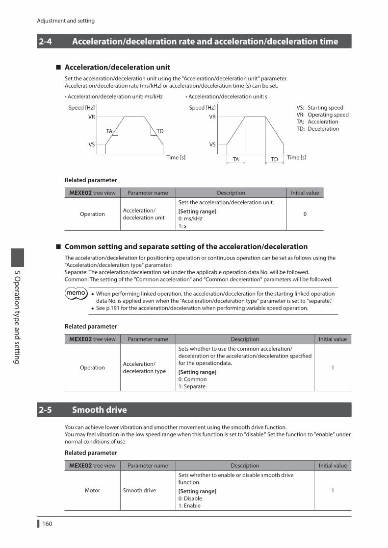
Adjustment and setting
5 Operation type and setting
160
2-4 Acceleration/deceleration rate and acceleration/deceleration time
Acceleration/deceleration unitSet the acceleration/deceleration unit using the "Acceleration/deceleration unit" parameter.Acceleration/deceleration rate (ms/kHz) or acceleration/deceleration time (s) can be set.
Speed [Hz] Speed [Hz]
Time [s] Time [s]
VR
VS
VR
VS
TA TD
TA TD
• Acceleration/deceleration unit: ms/kHz • Acceleration/deceleration unit: s
VS: Starting speedVR: Operating speedTA: AccelerationTD: Deceleration
Related parameter
MEXE02 tree view Parameter name Description Initial value
OperationAcceleration/deceleration unit
Sets the acceleration/deceleration unit.
[Setting range] 0: ms/kHz 1: s
0
Common setting and separate setting of the acceleration/decelerationThe acceleration/deceleration for positioning operation or continuous operation can be set as follows using the "Acceleration/deceleration type" parameter:Separate: The acceleration/deceleration set under the applicable operation data No. will be followed.Common: The setting of the "Common acceleration" and "Common deceleration" parameters will be followed.
• When performing linked operation, the acceleration/deceleration for the starting linked operation data No. is applied even when the "Acceleration/deceleration type" parameter is set to "separate."
• See p.191 for the acceleration/deceleration when performing variable speed operation.
Related parameter
MEXE02 tree view Parameter name Description Initial value
OperationAcceleration/deceleration type
Sets whether to use the common acceleration/deceleration or the acceleration/deceleration specified for the operationdata.
[Setting range] 0: Common 1: Separate
1
2-5 Smooth drive
You can achieve lower vibration and smoother movement using the smooth drive function.You may feel vibration in the low speed range when this function is set to "disable." Set the function to "enable" under normal conditions of use.
Related parameter
MEXE02 tree view Parameter name Description Initial value
Motor Smooth drive
Sets whether to enable or disable smooth drive function.
[Setting range] 0: Disable 1: Enable
1

Adjustment and setting5 O
peration type and setting
161
2-6 Speed filter
If the “Filter selection” parameter is set to “speed filter,” the motor response can be adjusted with the “Speed filter” parameter.When the speed filter level is raised, vibration can be suppressed during low-speed operation, and starting/stopping of the motor will become smooth. Note, however, that an excessively high filter level will result in lower synchronicity with commands. Set an appropriate value according to the specific load and purpose.
Related parameter
MEXE02 tree view Parameter name Description Initial value
Motor
Filter selection
Sets the filter function to adjust the motor response.
[Setting range] 0: Speed filter 1: Moving average filter
0
Speed filterAdjusts the motor response.
[Setting range] 0 to 200 ms
1
Setting speed
Motor speed
MOVE output
END output
Setting speed
Motor speed
MOVE output
END output
When the “Speed lter” parameter is set to 0 ms
When the “Speed lter” parameter is set to 200 ms
When setting the value of the "Speed filter" parameter to "0," this function will be invalid.
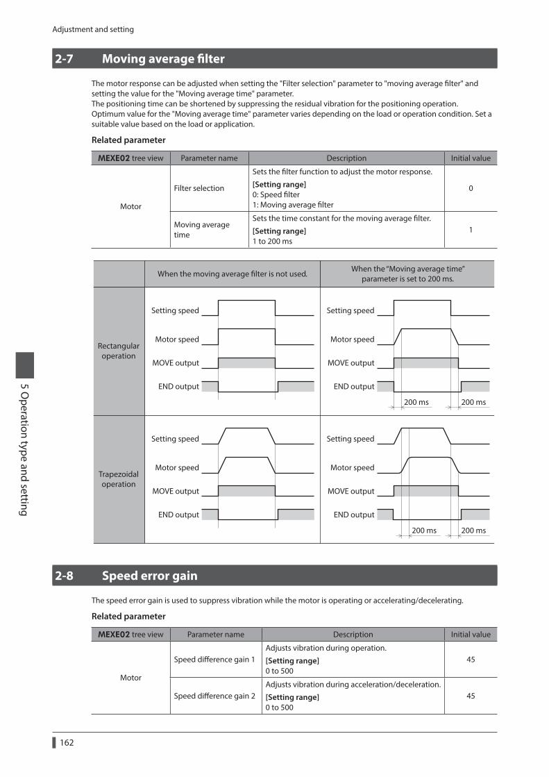
Adjustment and setting
5 Operation type and setting
162
2-7 Moving average filter
The motor response can be adjusted when setting the "Filter selection" parameter to "moving average filter" and setting the value for the "Moving average time" parameter. The positioning time can be shortened by suppressing the residual vibration for the positioning operation.Optimum value for the "Moving average time" parameter varies depending on the load or operation condition. Set a suitable value based on the load or application.
Related parameter
MEXE02 tree view Parameter name Description Initial value
Motor
Filter selection
Sets the filter function to adjust the motor response.
[Setting range] 0: Speed filter 1: Moving average filter
0
Moving average time
Sets the time constant for the moving average filter.
[Setting range] 1 to 200 ms
1
Setting speed
Motor speed
MOVE output
END output END output
END output END output
Setting speed
Motor speed
MOVE output
200 ms200 ms
200 ms200 ms
Setting speed
Motor speed
MOVE output
Setting speed
Motor speed
MOVE output
When the moving average lter is not used.
Rectangularoperation
Trapezoidaloperation
When the “Moving average time”parameter is set to 200 ms.
2-8 Speed error gain
The speed error gain is used to suppress vibration while the motor is operating or accelerating/decelerating.
Related parameter
MEXE02 tree view Parameter name Description Initial value
Motor
Speed difference gain 1Adjusts vibration during operation.
[Setting range] 0 to 500
45
Speed difference gain 2Adjusts vibration during acceleration/deceleration.
[Setting range] 0 to 500
45

Adjustment and setting5 O
peration type and setting
163
2-9 Control mode
The driver operates in one of two control modes: the normal mode, and the current control mode. If noise is heard during high-speed operation or there is notable vibration, it may be effective to switch to the current control mode.Note, however, that a slight delay may occur in the current control mode, compared to the normal mode, depending on the condition of the load. Keep the driver in the normal mode during normal conditions of use.
Related parameter
MEXE02 tree view Parameter name Description Initial value
Motor Control mode
Sets the control mode of the driver.
[Setting range] 0: Normal mode 1: Current control mode
0
2-10 Position loop gain, speed loop gain, speed loop integral time constant
These items are effective in the current control mode.Vibration that occurs while the motor is accelerating/decelerating or at standstill can be adjusted to an optimal value. (The optimal value varies depending on the equipment and operating conditions.)
Related parameter
MEXE02 tree view Parameter name Description Initial value
Motor
Position loop gain
Adjusts the motor response in reaction to the position deviation. When this value is increased, the deviation between the command position and actual position will be small. An excessively high value may increase the motor overshooting or cause motor hunting.
[Setting range] 1 to 50
10
Speed loop gain
Adjusts the motor response in reaction to the speed deviation. When this value is increased, the deviation between the command speed and actual speed will be small. An excessively high value may increase the motor overshooting or cause motor hunting.
[Setting range] 10 to 200
180
Speed loop integral time constant
Adjusts the deviation that cannot be adjusted with the speed loop gain. An excessively high value may slow the motor response. On the other hand, an excessively low value may cause motor hunting.
[Setting range] 100 to 2,000 (1=0.1 ms)
1,000

Adjustment and setting
5 Operation type and setting
164
2-11 Absolute-position backup system
This product can be used in the absolute-position backup mode when connecting an accessory battery set. Since the absolute position can be kept during an electrical outage or after turning off the power, the return-to-home operation is not required when the power is turned on. Refer to p.52 (AC power input), p.82 (DC power input) for accessory.
Related parameter
MEXE02 tree view Parameter name Description Initial value
Common Absolute back-up system
Sets whether to enable or disable absolute-position backup system.
[Setting range] 0: Disable 1: Enable
0
Setting of the absolute-position backup system
1. Turn off the driver main power and DC power supply, and then connect the battery to the battery connector (AC power input: CN10, DC power input: CN4).
2. Turn on the driver main power and DC power supply.
3. Set the "Absolute back-up system" parameter to "enable."
4. Turn off the driver main power and DC power supply, and then turn on again.
5. Since the "absolute position error alarm" generates at this time, reset the alarm using either of the following methods.− Turn the P-CLR input from ON to OFF. (The alarm will be reset at the OFF edge of the P-CLR input.)− Perform the reset of the absolute position error alarm using the MEXE02, OPX-2A or via RS-485 communication.
6. Perform the return-to-home operation or P-PRESET.
• Do not turn off the driver power supply before the return-to-home operation or P-PRESET is completed. The "absolute position error alarm" may generate when turning on the power supply next time.
• Even when the absolute-position backup system is used, the absolute position may be lost if the motor cable is disconnected. If this occurs, turn off the main power and DC power supply, disconnect the battery, and then set up again following above steps.
Specification of the absolute-position backup system
Data retention period 15 days [At an ambient temperature of 20 °C (68 °F), fully charged, motor standstill]
Charging time 32 hours [At an ambient temperature of 20 °C (68 °F)]
Operation range of multi-rotation
−167,772 to +167,772 revolutions

Operation type and function list5 O
peration type and setting
165
3 Operation type and function list
Return-to-home operation
Continuous operation Other operations
• JOG operation• Automatic return operation
Positioning operation
Speed
Time
Operation function
• Data number selecting operation• Direct positioning operation• Sequential positioning operation
Starting method
+
[Setting by operation data and parameters]
[Setting by parameters]
• I/OInput logic levelSTOP input actionOvertravel
• Coordination settingResolution (electronic gear)Wrap functionMotor rotation direction
• Motor functionOperating currentStandstill currentSpeed lterMoving average lter
• Operation functionAcceleration/deceleration typeAcceleration/deceleration unitJOG operationAutomatic return operation
• I/O functionInput functionInput logicOutput function
• I/O function (RS-485)Input functionOutput function
• Return-to-home functionHome position osetExternal sensor signal detectionReturn-to-home speedReturn-to-home starting direction
• Alarm/warningAlarm detectionWarning detection
Startingcommand
• Single-motion operation
Speed
Time
Operation data No.0
Operation data No.1
Startingcommand
• Linked-motion operation
Speed
Time
Dwelltime
Operation data No.0
Operation data No.1
Operation data No.0
Operation data No.1
Startingcommand
• Linked-motion 2 operation
Speed
Time
Operation data No.0
Startingcommand
• Push operation
• 3-sensor mode-LS +LSHOMES
• 2-sensor mode
-LS +LS
• Push mode • Position preset- side
mechanical end+ side
mechanical end
Motor operationTime
FWD input
RVS input
M0 to M5 input
Operation
Function

Positioning operation
5 Operation type and setting
166
4 Positioning operation
Positioning operation is one in which motor operating speed, position (travel amount) and other items are set as operation data and then executed. When the positioning operation is executed, the motor begins at the starting speed and accelerates until the operating speed is reached. Then, once the operating speed is reached, that speed is maintained. The motor decelerates when the stopping position approaches, and finally comes to a stop.The operation function can also be set in operation data. The operation function is how to operate consecutive operation data (example: operation data No.0, No.1, No.2).
4-1 Operation data
The following data are the operation data for positioning operation. Up to 64 operation data can be set (data Nos.0 to 63).
MEXE02 tree view Setting item Description Initial value
Operation data
PositionSets the position (distance) for positioning operation.
[Setting range] −8,388,608 to +8,388,607 step
0
Operating speed
Sets the operating speed in positioning operation.
[Setting range] 0 to 1,000,000 Hz
1,000
Acceleration
Sets the acceleration rate (acceleration time) in positioning operation.
[Setting range] 1 to 1,000,000 (1=0.001 ms/kHz or 1=0.001 s)
1,000
Deceleration
Sets the deceleration rate (deceleration time) in positioning operation.
[Setting range] 1 to 1,000,000 (1=0.001 ms/kHz or 1=0.001 s)
1,000
Operation mode
Selects how to specify the position (travel amount) in positioning operation.
[Setting range] 0: Incremental (INC) 1: Absolute (ABS)
0
Operation function
Sets the operation mode to execute positioning operation.
[Setting range] 0: Single-motion 1: Linked-motion 2: Linked-motion 2 3: Push
0
Dwell time
Sets the dwell time to be used in linked-motion 2 operation.
[Setting range] 0 to 50,000 (1=0.001 s)
0
Push currentSets the current rate of push-motion operation.
[Setting range] 0 to 1,000 (1=0.1%) *
200
Sequential positioning
Sets whether to enable or disable sequential positioning operation.
[Setting range] 0: Disable 1: Enable
0
* For the driver which is before the specification change, the setting range is 0 to 500 (1=0.1%). Refer to p.7 for details.

Positioning operation5 O
peration type and setting
167
z Position, operating speed, acceleration, decelerationThe acceleration/deceleration for positioning operation can be set as follows using the "Acceleration/deceleration type" parameter:Separate : The acceleration/deceleration set under the applicable operation data No. will be followed (Each 64 data for acceleration and deceleration).Common : The setting of the "Common acceleration" and "Common deceleration" parameter will be followed (Each one data for acceleration and deceleration).
When the starting speed < operating speed
Speed
Operating speed
Starting speed
Time
AccelerationDeceleration
Travel amount
When the starting speed ≥ operating speed
Speed
Starting speed
Operating speed
Time
Travel amount
z Operation modeThe following two operation modes are available:
Absolute (ABS) modeThe position (distance) from home is set [Absolute positioning].
Example: When positioning operation is performed with setting the starting point to 1,000 and setting the destination to +3,000 and −3,000
3,000
Starting point1,000
Travel amount 2,000Travel amount -4,000
Home0-3,000
Incremental (INC) modeEach motor destination becomes the starting point for the next movement. This mode is suitable when the same position (distance) is repeatedly used [Incremental positioning].
Example: When positioning operation is performed with setting the starting point to 1,000 and setting the destination to +3,000 and −3,000
4,000
Starting point1,000
Travel amount 3,000Travel amount -3,000
Home0-2,000
z Operation function, dwell timeThe following four operation function are available:
Operation function Description Ref.
Single-motion A single operation data set is executed. p.173
Linked-motionMultiple sets of operation data are linked to perform multi-variable speed operation
p.174
Linked-motion 2Dwell time (stop waiting time) can be set between operation data. Operation data whose rotation direction is different can also be linked.
p.175
Push-motionThis is an operation of continuously applying pressure on the load when pressing against the load during positioning operation.
p.177

Positioning operation
5 Operation type and setting
168
4-2 Starting method of positioning operation
The following three types are available in the starting method.
Starting method Description
Data number selecting operation
When the START input is turned ON with selecting the operation data No. by a combination of the M0 to M5 inputs, the positioning operation will perform.
Direct positioning operationWhen any of the MS0 to MS5 inputs is turned ON, the positioning operation corresponding to the input data No. will perform.
Sequential positioning operation
Positioning operation is performed to the next operation data No. every time a SSTART input signal is input.
Data number selecting operationSelect an operation data based on a combination of ON/OFF status of the M0 to M5 inputs. Refer p.93 for details.
Operation data No. M5 M4 M3 M2 M1 M0
0 OFF OFF OFF OFF OFF OFF
1 OFF OFF OFF OFF OFF ON
2 OFF OFF OFF OFF ON OFF
· · ·
· · ·
· · ·
· · ·
· · ·
· · ·
· · ·
61 ON ON ON ON OFF ON
62 ON ON ON ON ON OFF
63 ON ON ON ON ON ON
Operating method
1) Check the READY output is ON.
2) Select the operation data No. by a combination of the M0 to M5 inputs and turn the START input ON.
3) The motor starts positioning operation.
4) Check that the READY output has been turned OFF and turn the START input OFF.
5) When the positioning operation is completed, the READY output will be turned ON.
START input *
MOVE output
END output
READY output
Motor operation
M0 to M5 input * No.0 No.1
No.1
ONOFF
ONOFF
ONOFF
ONOFF
ONOFF
51
2
3
4
* In direct I/O, turn the START input ON after setting the M0 to M5 inputs. In remote I/O, the operation will be performed even when turning the M0 to M5 inputs and the START input ON simultaneously.

Positioning operation5 O
peration type and setting
169
Direct positioning operationWhen any of the MS0 to MS5 inputs is turned ON, the positioning operation corresponding to the input data No. will perform. Since the positioning operation is enabled by turning any of the MS0 to MS5 inputs ON, you can save the step of selecting the operation data No.The operation data assigning to the MS0 to MS5 inputs will be set by parameters.
Related parameter
MEXE02 tree view Parameter name Description Initial value
I/O
MS0 operation No. selection
Sets the operation data No. corresponding to MS0 to MS5 input.
[Setting range] 0 to 63
0
MS1 operation No. selection 1
MS2 operation No. selection 2
MS3 operation No. selection 3
MS4 operation No. selection 4
MS5 operation No. selection 5
Operating method
1) Check the READY output is ON.
2) Turn the MS0 input ON.
3) The motor starts positioning operation.
4) Check that the READY output has been turned OFF and turn the MS0 input OFF.
5) When the positioning operation is completed, the READY output will be turned ON.
MOVE output
END output
READY output
Motor operation
MS0 input
Operation data No. corresponding to the MS0 input
ONOFF
ONOFF
ONOFF
ONOFF
1
3
4 5
2

Positioning operation
5 Operation type and setting
170
Sequential positioning operationIn sequential positioning operation, whenever turning the SSTART input ON, the positioning operation for the following operation data No. will be performed. This function is useful when multiple positioning operations must be performed sequentially, because there is no need to select each data number.When the “sequential positioning” of operation data is executed up to the data No. set to "disable", the operation returns to the original data No. that was selected before starting the sequential positioning operation. And the sequential positioning operation will start again.If the starting point for the sequential positioning operation is changed using the M0 to M5 inputs or the MS0 to MS5 inputs, multiple sequential positioning operations can be set. It is convenient for setting a different operating pattern for each component or each process of works.
z When the operating pattern is one type
1) The positioning operation for the operation data No.0 is performed by turning the SSTART input ON.
2) After the operation 1) is completed, when turning the SSTART input ON again, the positioning operation for the operation data No.1 will be performed.
3) After the operation 2) is completed, when turning the SSTART input ON again, the positioning operation for the operation data No.2 will be performed.
4) After the operation 3) is completed, when turning the SSTART input ON again, the positioning operation will be performed by returning to the operation data No.0 because the sequential positioning for the operation data No.3 has been set to "disable."
Setting exampleOperation data Sequential positioning
No.0
EnableNo.1
No.2
No.3 Disable
Operationdata No.0
Operationdata No.1
2) SSTART =ON
3) SSTART =ON
4) SSTART =ON
1) SSTART =ON Operation
data No.2

Positioning operation5 O
peration type and setting
171
z When the operating patterns are multiple
1) After selecting the operation data No.3 that is the starting point for the sequential positioning operation, the positioning operation will be performed by turning the START input ON.
2) After the operation 1) is completed, when turning the SSTART input ON again, the positioning operation for the operation data No.4 will be performed.
3) After the operation 2) is completed, when turning the SSTART input ON again, the positioning operation for the operation data No.5 will be performed.
4) After the operation 3) is completed, when turning the SSTART input ON again, the positioning operation will be performed by returning to the operation data No.3 because the sequential positioning for the operation data No.6 has been set to "disable."
5) After the operation 4) is completed, the positioning operation is performed by selecting the operation No.7 and turning the START input ON.
6) The operation data No.7 becomes a starting point for a new sequential positioning operation.
7) After the operation 5) is completed, when turning the SSTART input ON again, the positioning operation for the operation data No.8 will be performed.
8) When turning the SSTART input ON again after the operation 6) is completed, the positioning operation will be performed by returning to the operation data No.7 because the sequential positioning for the operation data No.9 has been set to "disable."
Setting exampleOperation data Sequential positioning
No.3
EnableNo.4
No.5
No.6 Disable
No.7Enable
No.8
No.9 Disable
Operationdata No.3
Operationdata No.4
2) SSTART =ON
3) SSTART =ON
4) SSTART =ON
1) M0, M1=ON START=ON
5) M0, M1, M2=ON START=ON
Operationdata No.5
Operationdata No.7
6) SSTART =ON
7) SSTART =ONOperation
data No.8
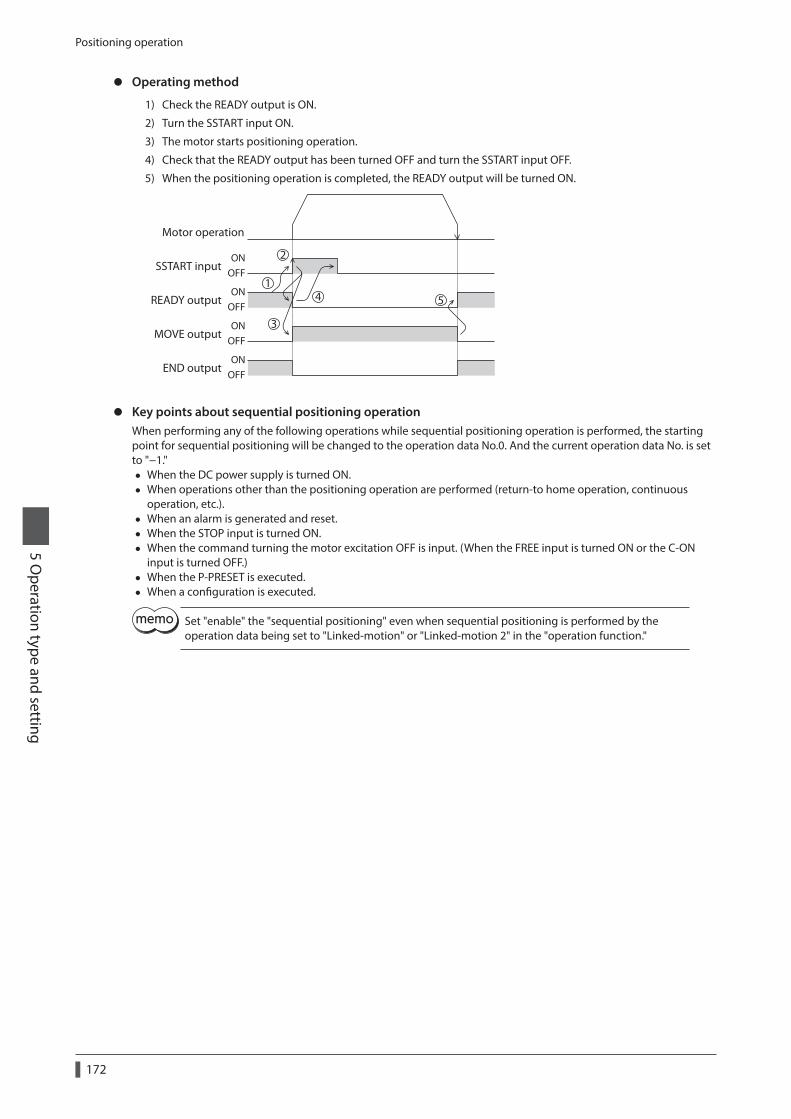
Positioning operation
5 Operation type and setting
172
z Operating method
1) Check the READY output is ON.
2) Turn the SSTART input ON.
3) The motor starts positioning operation.
4) Check that the READY output has been turned OFF and turn the SSTART input OFF.
5) When the positioning operation is completed, the READY output will be turned ON.
MOVE output
END output
1
3
4 5
2
READY output
Motor operation
SSTART inputON
OFF
ONOFF
ONOFF
ONOFF
z Key points about sequential positioning operationWhen performing any of the following operations while sequential positioning operation is performed, the starting point for sequential positioning will be changed to the operation data No.0. And the current operation data No. is set to "−1."
• When the DC power supply is turned ON. • When operations other than the positioning operation are performed (return-to home operation, continuous
operation, etc.). • When an alarm is generated and reset. • When the STOP input is turned ON. • When the command turning the motor excitation OFF is input. (When the FREE input is turned ON or the C-ON
input is turned OFF.) • When the P-PRESET is executed. • When a configuration is executed.
Set "enable" the "sequential positioning" even when sequential positioning is performed by the operation data being set to "Linked-motion" or "Linked-motion 2" in the "operation function."

Positioning operation5 O
peration type and setting
173
4-3 Operation function
Single-motion operationThe positioning operation is performed only once using a single operation data set.
z Example of single-motion operation
Operation example Speed
Operating speed of No.1: 5,000
Starting speed: 500
Position5,0000
Operation dataNo.1
Operating method
1) Check the READY output is ON.
2) Select the operation data No.1 by turning the M0 input ON and turn the START input ON.
3) The motor starts the positioning operation for the operation data No.1.
4) Check that the READY output has been turned OFF and turn the START input OFF.
5) When the positioning operation is completed, the READY output will be turned ON.
START input *
MOVE output
END output
READY output
Motor operation
M0 to M5 input * No.0 No.1
No.1
ONOFF
ONOFF
ONOFF
ONOFF
ONOFF
51
2
3
4
* In direct I/O, turn the START input ON after setting the M0 to M5 inputs. In remote I/O, the operation will be performed even when turning the M0 to M5 inputs and the START input ON simultaneously.

Positioning operation
5 Operation type and setting
174
Linked-motion operationWhen the “operation function” is set to “linked-motion” using operation data, positioning operation based on the next data number will be performed without stopping the motor.If operation data includes data for which “single-motion” or “push” is set, the motor will stop after the positioning with respect to the “single” or “push” operation data is completed.A maximum of four operation data can be linked. Note that only operation data of the same direction can be linked.
• Multiple operation data of different directions cannot be linked. An operation data error alarm will generate during operation.
• Up to four sets of operation data can be linked. When combining the linked-motion operation and the linked-motion 2 operation, make sure the total number of linked operation data sets does not exceed four. When linked-motion operation is performed with five or more sets of operation data linked together, an operation data error alarm will generate upon start of operation.
• No.0 will not be linked even when “linked-motion” is set for data No.63, because the operation pertaining to No.63 will be processed independently.
• The acceleration/deceleration in linked-motion operation corresponds to the acceleration/ deceleration specified for the operation data No. with which the linked-motion operation is started.
• When the operation data linked last is being set to "push," the push speed is applied as the starting speed.
z Example of linked-motion operation
Operation example Speed
Operating speed of No.2: 10,000
Operating speed of No.1: 5,000
Starting speed: 500
Position5,000 20,0000
No.1 No.2
Operating method
1) Check the READY output is ON.
2) Select the operation data No.1 by turning the M0 input ON and turn the START input ON.
3) The motor starts the positioning operation in which the operation data No.1 and No.2 are linked.
4) Check that the READY output has been turned OFF and turn the START input OFF.
5) When the positioning operation is completed, the READY output will be turned ON.
START input *
MOVE output
END output
READY output
Motor operation
M0 to M5 input * No.0 No.1ON
OFF
ONOFF
ONOFF
ONOFF
ONOFF
No.1 No.2
1
2
3
4 5
* In direct I/O, turn the START input ON after setting the M0 to M5 inputs. In remote I/O, the operation will be performed even when turning the M0 to M5 inputs and the START input ON simultaneously.

Positioning operation5 O
peration type and setting
175
Linked-motion 2 operationBy setting the “operation function” of operation data to “Linked-motion2,” an operation data whose rotation direction is different can be linked. In this case, the system stops for the dwell time after each positioning operation, and then performs operation according to the next operation data. If operation data includes data for which “single-motion” or “push” is set, the motor will stop after the positioning with respect to the “single” or “push” operation data is completed.
• Up to four sets of operation data can be linked. When combining the linked-motion operation and the linked-motion 2 operation, make sure the total number of linked operation data sets does not exceed four. When linked-motion operation is performed with five or more sets of operation data linked together, an operation data error alarm will generate upon start of operation.
• No.0 will not be linked even when “linked-motion2” is set for data No.63, because the operation pertaining to No.63 will be processed independently.
z Example of linked-motion 2 operation
Operation example Speed
Operating speed of No.1: 5,000
Operating speed of No.2: -3,000
Starting speed: 500
Position5,0002,000
0
Operation dataNo.1
Operation data No.2
Stop for 1 s
Operating method
1) Check the READY output is ON.
2) Select the operation data No.1 by turning the M0 input ON and turn the START input ON.
3) The motor starts the positioning operation for the operation data No.1.
4) Check that the READY output has been turned OFF and turn the START input OFF.
5) When the positioning operation 3) is completed, the MOVE output will be turned OFF.
6) When the dwell time has passed, the positioning operation for the operation data No.2 will automatically start. At the same time, the MOVE output will be turned ON.
7) When the positioning operation for the operation data No.2 is completed, the READY output will be turned ON.
START input *
MOVE output
END output
READY output
Motor operation
Dwell time1 s
M0 to M5 input * No.0 No.1ON
OFF
ONOFF
ONOFF
ONOFF
ONOFF
No.1
No.2
1
2
3
4
5 67
* In direct I/O, turn the START input ON after setting the M0 to M5 inputs. In remote I/O, the operation will be performed even when turning the M0 to M5 inputs and the START input ON simultaneously.

Positioning operation
5 Operation type and setting
176
z Example of linked-motion 2 operation; When combining the linked-motion operation and the linked-motion 2 operation
Operation example
Speed
Operating speed of No.3: 7,000
Operating speed of No.4: -7,000
Operating speed of No.1: 3,000
Operating speed of No.2: 5,000
Starting speed: 500
Position5,000 40,00015,0000
No.1 No.2 No.3
No.4
Stop for 1 s
Operating method
1) Check the READY output is ON.
2) Select the operation data No.1 by turning the M0 input ON and turn the START input ON.
3) The motor starts the positioning operation in which the operation data from No.1 to No.3 are linked.
4) Check that the READY output has been turned OFF and turn the START input OFF.
5) When the positioning operation 3) is completed, the MOVE output will be turned OFF.
6) When the dwell time has passed, the positioning operation for the operation data No.4 will automatically start. At the same time, the MOVE output will be turned ON.
7) When the positioning operation for the operation data No.4 is completed, the READY output will be turned ON.
START input *
MOVE output
END output
READY output
Motor operation
Dwell time1 s
M0 to M5 input * No.0 No.1ON
OFF
ONOFF
ONOFF
ONOFF
ONOFF
No.1 No.2 No.3
No.4
1
5 67
2
3
4
* In direct I/O, turn the START input ON after setting the M0 to M5 inputs. In remote I/O, the operation will be performed even when turning the M0 to M5 inputs and the START input ON simultaneously.

Positioning operation5 O
peration type and setting
177
4-4 Push-motion operation
When the "operation function" is set to "push," the motor performs an operation of continuously applying pressure on the load when pressing against the load. In push-motion operation, the motor performs constant speed operation at the operating speed of the selected operation data No. but the acceleration/deceleration will not be applied.The motor becomes push-motion status when pressing against the load, and the TLC output and READY output are turned ON. The set current value of push-motion operation is applied to the motor current.When the operation was completed with non-push-motion status, the motor stops, and the END output and READY output are turned ON. The set current of push-motion operation is applied to the motor current at standstill.When the STOP input is turned ON, the motor stops, and the END output and READY output are turned ON.The STOP current is applied to the motor current at standstill.
Do not perform push-motion operation with geared motors. Doing so may cause damage to the motor or gear part.
• Regardless of resolution, the maximum speed of push-motion operation is 500 r/min. If the push-motion operation is started by setting higher speed than 500 r/min, an operation data error alarm will generate. For the driver which is before the specification change, the maximum speed of push-motion operation is 30 r/min. Refer to p.8 for details.
• If push-motion operation is performed for a long time while a large push-motion current is set, the driver may increase heat generation and generate the main circuit overheat alarm.
z Example of push-motion operation; When it had pressed against the load
Operation example Speed
Operating speed of No.1: 500
Position
Push status
5,0000
Operation dataNo.1
Operating method
1) Check the READY output is ON.
2) Select the operation data No.1 by turning the M0 input ON and turn the START input ON.
3) The motor starts the positioning operation for the operation data No.1.
4) Check that the READY output has been turned OFF and turn the START input OFF.
5) When the motor becomes push-motion status, the TLC output will be turned ON and then the READY output will be turned ON.
START input *
MOVE output
END output
READY output
Motor operation
Push-motion status
M0 to M5 input * No.0 No.1
No.1
ONOFF
ONOFF
ONOFF
ONOFF
ONOFF
TLC outputON
OFF
1
2
3
5
4
* In direct I/O, turn the START input ON after setting the M0 to M5 inputs. In remote I/O, the operation will be performed even when turning the M0 to M5 inputs and the START input ON simultaneously.

Positioning operation
5 Operation type and setting
178
z Example of push-motion operation; When it had not pressed against the load
Operation example Speed
Operating speed of No.1: 500
Position5,0000
Operation dataNo.1
Operating method
1) Check the READY output is ON.
2) Select the operation data No.1 by turning the M0 input ON and turn the START input ON.
3) The motor starts the positioning operation for the operation data No.1.
4) Check that the READY output has been turned OFF and turn the START input OFF.
5) When the motor reaches to the target position, the operation will be stopped and the READY output will be turned ON. Since the motor did not become push-motion status, the TLC output remains OFF.
START input *
MOVE output
END output
READY output
Motor operation
M0 to M5 input * No.0 No.1
No.1
ONOFF
ONOFF
ONOFF
ONOFF
ONOFF
TLC outputON
OFF
1
2
3
4 5
* In direct I/O, turn the START input ON after setting the M0 to M5 inputs. In remote I/O, the operation will be performed even when turning the M0 to M5 inputs and the START input ON simultaneously.
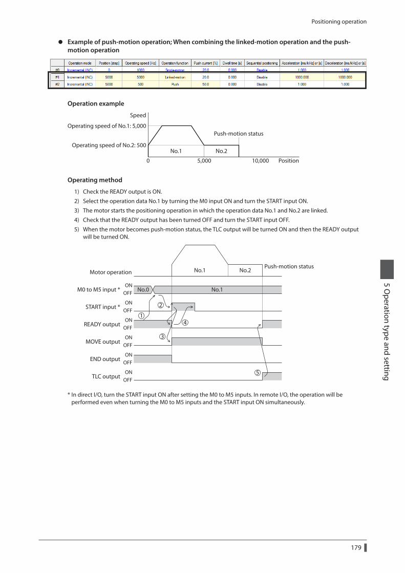
Positioning operation5 O
peration type and setting
179
z Example of push-motion operation; When combining the linked-motion operation and the push-motion operation
Operation example
Speed
Operating speed of No.1: 5,000
Operating speed of No.2: 500
Position5,000 10,0000
No.1 No.2
Push-motion status
Operating method
1) Check the READY output is ON.
2) Select the operation data No.1 by turning the M0 input ON and turn the START input ON.
3) The motor starts the positioning operation in which the operation data No.1 and No.2 are linked.
4) Check that the READY output has been turned OFF and turn the START input OFF.
5) When the motor becomes push-motion status, the TLC output will be turned ON and then the READY output will be turned ON.
START input *
MOVE output
END output
READY output
Motor operationPush-motion status
M0 to M5 input * No.0 No.1
No.1 No.2
ONOFF
ONOFF
ONOFF
ONOFF
ONOFF
TLC outputON
OFF
1
2
3
4
5
* In direct I/O, turn the START input ON after setting the M0 to M5 inputs. In remote I/O, the operation will be performed even when turning the M0 to M5 inputs and the START input ON simultaneously.

Return-to-home operation
5 Operation type and setting
180
5 Return-to-home operation
Return-to-home is an operation in which the reference point of positioning (mechanical home position) is detected automatically. Return-to-home operation is performed to return to the home position from the current position when the power supply is turned on or the positioning operation is completed.Return-to-home operation can be performed in the following four modes:
Operation type Description Feature
3-sensor modeThe motor operates at the "operating speed of home-seeking." When the HOME sensor is detected, the motor will stop and the stop position will be the home position.
• 3 external sensors are needed. *3
•Operating speed is high (Operating speed of home-seeking).
2-sensor mode
The motor operates at the "starting speed of home-seeking." When the limit sensor is detected, the motor will rotate in the reverse direction and escape from the limit sensor. After escaping from the limit sensor, the motor will move 200 steps and stop, and then the stop position will be the home position. *2
• 2 external sensors are needed.
•Operating speed is low (Starting speed of home-seeking).
Push mode *1
The motor operates at the "starting speed of home-seeking." When the moving part for the motor is pressed against a mechanical stopper etc., the motor will rotates in the reverse direction. After reversing, the motor will move 200 steps and stop, and then the stop position will be the home position. *2
•No external sensor is needed.
•Operating speed is low (Starting speed of home-seeking).
Position preset
When executing the P-PRESET at the position that the motor stops, the command position will be the value of the "Preset position" parameter. The home position can be set to any position.
•No external sensor is needed.
• The home position can be set to any position.
*1 Do not perform push-mode return-to-home operation for geared motors.*2 It moves 200 steps regardless of resolution. Therefore, the actual travel distance may vary according to resolution.*3 In the case of a rotating mechanism, even when using one external sensor, the home position can be detected.
Set to the 3-sensor mode, and connect the HOME sensor only.
Additional function
Additional function2-sensor mode 3-sensor mode
Push modePosition preset Related parameter
Home offset Possible Not possible • Position offset of home-seeking
External sensor (signal) detection
Possible Not possible • SLIT detection with home-seeking
• TIM signal detection with home-seeking
Command position after returning to home
The position becomes "0"
Any position • Preset position
z Home offsetThis is a function to perform positioning operation of the offset amount set by the parameter after return-to-home operation and to set the stop position to the home position. The position set by the home offset is called "electrical home" in distinction from the usual home position.If the amount of offset from mechanical home is “0,” the mechanical home and electrical home will become the same.
Mechanical home
-LS HOMES +LS
Electrical home
Return-to-home operation
Oset operation

Return-to-home operation5 O
peration type and setting
181
z Detecting the external sensor (signal)When detecting the home, use of the SLIT input and/or TIM signal will increase the accuracy of home detection.
When the TIM output is used, set the resolution to be an integral multiple of 50.
z Command position after returning to homeWhen executing the P-PRESET at the position that the motor stops, the command position will be the value of the "Preset position" parameter.
Parameters related to return-to-home operation
MEXE02 tree view Parameter name Description Initial value
Home operation
Home-seeking mode
Sets the mode for return-to-home operation.
[Setting range] 0: 2-sensor mode 1: 3-sensor mode 2: Push mode
1
Operating speed of home-seeking
Sets the operating speed for return-to-home operation.
[Setting range] 1 to 1,000,000 Hz
1,000
Acceleration/deceleration of home-seeking
Sets the acceleration/deceleration rate (acceleration/deceleration time) for return-to-home operation.
[Setting range] 1 to 1,000,000 (1=0.001 ms/kHz or 1=0.001 s)
1,000
Starting speed of home-seeking
Sets the starting speed for return-to-home operation.
[Setting range] 1 to 1,000,000 Hz
500
Position offset of home-seeking
Sets the amout of offset from mechanical home.
[Setting range] −8,388,608 to 8,388,607 step
0
Starting direction of home-seeking
Sets the starting direction for home detection.
[Setting range] 0: Negative side 1: Positive side
1
SLIT detection with home-seeking
Sets whether or not to concurrently use the SLIT input for return-to-home operation.
[Setting range] 0: Disable 1: Enable
0
TIM signal detection with home-seeking
Sets whether or not to concurrently use the TIM signal for return-to-home operation.
[Setting range] 0: Disable 1: Enable
0
Operating current of home-seeking with push-motion
Sets the operating current for push-motion return-to-home operation based on the rated current being 100%.
[Setting range] 0 to 1,000 (1=0.1%)
1,000

Return-to-home operation
5 Operation type and setting
182
z Operation example (when using 3-sensor mode)
Operating sequence in seeing a time axis
SpeedOperating speedof home-seeking
Starting speedof home-seeking
Starting speed of home-seeking
Time
Electrical home
Mechanical home
Acceleration/deceleration
of home-seeking
HOMES inputON
OFF
Operating sequence in seeing a travel amount
Speed HOMES inputOperating speed
of home-seeking
Starting speedof home-seeking
Position0Starting position
Electrical home
Mechanical home
z Operating method
1) Check the READY output is ON.
2) Turn the HOME input ON.
3) Return-to-home operation will be started.
4) Check that the READY output has been turned OFF and turn the HOME input OFF.
5) When return-to-home operation is completed, the HOME-P output will be turned ON.
HOME input
MOVE output
END output
READY output
Motor operation
ONOFF
ONOFF
ONOFF
ONOFF
HOME-P outputON
OFF
HOMES inputON
OFF
1
2
4
3
5

Return-to-home operation5 O
peration type and setting
183
5-1 Operation sequence
3-sensor modeVS: Starting speed of home-seekingVR: Operating speed of home-seekingVL: Last speed of return-to-home (When VS < 500 Hz: VS, When VS ≥ 500 Hz: 500 Hz)- - - Broken line indicates a home offset move.
Between HOMES and -LS
Between HOMES and +LS
HOMES
-LS
+LS
Starting position ofreturn-to-home operation
Starting direction of return-to-home operation: Positive side
Starting direction of return-to-home operation: Negative side
+ side
- side
-LS +LS
VLVR
VR
VS
VL VS
VR
VR
VS
VS
VR
VR
VS
VS
VR
VR
VS
VS
VR
VR
VS
VS
VR
VR
VS
VS
VR
VR
VS
VS
VR
VR
VS
VS
VR
VR
VS
VS
VR
VR
VS
VS
VL
VL
VL
VL
VL
VL
VL
VL
HOMES
+ side
- side
-LS +LSHOMES
+ side
- side
-LS +LSHOMES
+ side
- side
-LS +LSHOMES
+ side
- side
-LS +LSHOMES
+ side
- side
-LS +LSHOMES
+ side
- side
-LS +LSHOMES
+ side
- side
-LS +LSHOMES
+ side
- side
-LS +LSHOMES
+ side
- side
-LS +LSHOMES
z When using the HOME sensor onlyIf the limit sensor is not used such as a rotating mechanism, operation sequences are as follows.
HOMES
Not HOMES
Starting position ofreturn-to-home operation
Starting direction of return-to-home operation: Positive side
Starting direction of return-to-home operation: Negative side
+ side
- side
HOMES
+ side
- side
HOMES
+ side
- side
HOMES
+ side
- side
VR
VR
VS
VS
VR
VR
VS
VS
VR
VR
VS
VS
VR
VR
VS
VS
VL
VL
VL
VL
HOMES
Depending on the setting value of the "Acceleration/deceleration of home-seeking" parameter, the motor may decelerate to a stop in excess of the HOME sensor after the HOME sensor was detected. Since there is a risk of contact if the distance between the mechanical end and the HOME sensor is close, provide enough distance between them.

Return-to-home operation
5 Operation type and setting
184
z When concurrently using the SLIT input and/or TIM signalAfter the HOME sensor is detected, the operation will continue until the external sensor (signal) will be detected. If the external sensor (signal) is detected while the HOME sensor is ON, the return-to-home operation will complete.
Starting direction of return-to-home operation: Positive sideSignal type
Starting direction of return-to-home operation: Negative side
VR
VR
VS
VS
VR
VR
VS
VS VL
VL+ side
- side
-LS +LSHOMES
SLITOFFON
SLITOFFON
+ side
- side
-LS +LSHOMES
VR
VR
VS
VS
VR
VR
VS
VS VL
VL+ side
- side
-LS +LSHOMES
TIMOFFON
TIMOFFON
+ side
- side
-LS +LSHOMES
SLIT input
TIM signal
SLIT inputand
TIM signal
VR
VR
VS
VS
VR
VR
VS
VS VL
VL+ side
- side
-LS +LSHOMES
TIMOFFON
TIMOFFON
SLITOFFON
SLITOFFON
+ side
- side
-LS +LSHOMES
2-sensor modeVS: Starting speed of home-seekingVR: Operating speed of home-seekingVL: Last speed of return-to-home (When VS < 500 Hz: VS, When VS ≥ 500 Hz: 500 Hz)- - - Broken line indicates a home offset move.
*
*
*
*
*
*
Between -LS and +LS
-LS
+LS
Starting position ofreturn-to-home operation
Starting direction of return-to-home operation: Positive side
Starting direction of return-to-home operation: Negative side
+ side
- side
-LS +LS
+ side
- side
-LS +LS
+ side
- side
-LS +LS
+ side
- side
-LS +LS
+ side
- side
-LS +LS
+ side
- side
-LS +LS
VR
VR
VS
VS
VR
VR
VS
VS
VR
VR
VS
VS
VR
VR
VS
VS
VR
VR
VS
VS
VR
VR
VS
VS
* After pulling out of the limit sensor, the motor will move 200 steps.

Return-to-home operation5 O
peration type and setting
185
z When concurrently using the SLIT input and/or TIM signalWhen the limit sensor is detected, the motor will rotate in the reverse direction and escape from the limit sensor. After escaping from the limit sensor, the motor will move 200 steps and stop once. Then, the motor operation will continue until the external sensor (signal) will be detected. When the external sensor (signal) is detected, return-to-home operation will complete.
**
*
*
*
*
SLIT input
TIM signal
SLIT inputand
TIM signal
+ side
- side
-LS +LS
+ side
- side
-LS +LSVR
VR
VS
VS
VR
VR
VS
VS
SLITOFFON
SLITOFFON
+ side
- side
-LS +LS
+ side
- side
-LS +LSVR
VR
VS
VS
VR
VR
VS
VS
SLITOFFON
SLITOFFON
+ side
- side
-LS +LS
+ side
- side
-LS +LSVR
VR
VS
VS
VR
VR
VS
VS
TIMOFFON
TIMOFFON
TIMOFFON
TIMOFFON
VL
VL
VL
VL
VL
VL
Starting direction of return-to-home operation: Positive side
Starting direction of return-to-home operation: Negative sideSignal type
* After pulling out of the limit sensor, the motor will move 200 steps.
Push modeVS: Starting speed of home-seekingVR: Operating speed of home-seekingVL: Last speed of return-to-home (When VS < 500 Hz: VS, When VS ≥ 500 Hz: 500 Hz)- - - Broken line indicates a home offset move.
*
*
*
*
*
*
Betweenmechanical ends
- sidemechanical end
+ sidemechanical end
Starting position ofreturn-to-home operation
Starting direction of return-to-home operation: Positive side
Starting direction of return-to-home operation: Negative side
+ side
- side
- sidemechanical end
+ sidemechanical end
+ side
- side
- sidemechanical end
+ sidemechanical end
+ side
- side
- sidemechanical end
+ sidemechanical end
+ side
- side
- sidemechanical end
+ sidemechanical end
+ side
- side
- sidemechanical end
+ sidemechanical end
+ side
- side
- sidemechanical end
+ sidemechanical end
VR
VR
VS
VS
VR
VR
VS
VS
VR
VR
VS
VS
VR
VR
VS
VS
VR
VR
VS
VS
VR
VR
VS
VS
* The motor will move 200 steps from the mechanical end.

Return-to-home operation
5 Operation type and setting
186
z When concurrently using the SLIT input and/or TIM signalWhen the moving part for the motor is pressed against a mechanical stopper etc., the motor will rotates in the reverse direction. After reversing, the motor will move 200 steps and stop once. Then, the motor operation will continue until the external sensor (signal) will be detected. When the external sensor (signal) is detected, return-to-home operation will complete.
*
*
**
*
*
Starting direction of return-to-home operation: Positive side
Starting direction of return-to-home operation: Negative sideSignal type
SLIT input
TIM signal
SLIT inputand
TIM signal
+ side
- side
- sidemechanical end
+ sidemechanical end
+ side
- side
- sidemechanical end
+ sidemechanical end
VR
VR
VS
VS
VR
VR
VS
VS
SLITOFFON
SLITOFFON
+ side
- side
- sidemechanical end
+ sidemechanical end
+ side
- side
- sidemechanical end
+ sidemechanical end
VR
VR
VS
VS
VR
VR
VS
VS
SLITOFFON
SLITOFFON
+ side
- side
- sidemechanical end
+ sidemechanical end
+ side
- side
- sidemechanical end
+ sidemechanical end
VR
VR
VS
VS
VR
VR
VS
VS
TIMOFFON
TIMOFFON
TIMOFFON
TIMOFFON
VL
VL
VL
VL
VL
VL
* The motor will move 200 steps from the mechanical end.
• Do not perform push-mode return-to-home operation for geared motors. Doing so may cause damage to the motor.
• The maximum speed for the push-mode is 500 r/min on the motor output shaft regardless of resolution. Starting return-to-home operation with setting faster speed than 500 r/min may cause damage to the motor.

Return-to-home operation5 O
peration type and setting
187
5-2 Position preset
When the P-PRESET is executed, the command position is set as the value of the "Preset position" parameter.However, the preset will not execute in the following conditions.
• When the motor is operating • When an alarm is present
z Related parameter
MEXE02 tree view Parameter name Description Initial value
Coordinates Preset positionSets the preset position.
[Setting range] −8,388,608 to 8,388,607 step
0
z Operating method
1) Check the READY output is ON.
2) Turn the P-PRESET input ON
3) When the driver internal processing is completed, the HOME-P output will be turned ON.
4) Check the HOME-P output has been turned ON, and then turn the P-PRESET input OFF.
P-PRESET input
HOME-P output
READY output
Command position Preset positionON
OFF
ONOFF
ONOFF
ONOFF
1
2
3
4

Continuous operation
5 Operation type and setting
188
6 Continuous operation
The motor operates continuously while the FWD or RVS input is ON.Operation is performed based on the FWD or RVS input and the operating speed corresponding to the selected operation data No. When the operation data No. is changed during continuous operation, the speed will change to the speed specified by the new operation data No.When the FWD or RVS input is turned OFF, the motor will decelerate to a stop. If the signal of the same direction is turned ON again during deceleration, the motor will accelerate and continue operating.If the FWD and RVS inputs are turned ON simultaneously, the motor will decelerate to a stop.
Operation dataOperation data for continuous operation are as follows.
MEXE02 tree view Setting item Description Initial value
Operation data
Operating speedSets the operating speed in continuous operation.
[Setting range] 1 to 1,000,000 Hz
1,000
Acceleration
Sets the acceleration rate (acceleration time) in continuous operation. *
[Setting range] 1 to 1,000,000 (1=0.001 ms/kHz or 1=0.001 s)
1,000
Deceleration
Sets the deceleration rate (deceleration time) in continuous operation. *
[Setting range] 1 to 1,000,000 (1=0.001 ms/kHz or 1=0.001 s)
1,000
* The acceleration/deceleration for continuous operation can be set as follows using the "Acceleration/deceleration type" parameter: Separate : The acceleration/deceleration set under the applicable operation data No. will be followed (Each 64 data for acceleration and deceleration). Common : The setting of the "Common acceleration" and "Common deceleration" parameter will be followed (Each one data for acceleration and deceleration).
Speed
Operating speed
Operating speed
FWD inputOFFON
RVS inputOFFON
Starting speed
Starting speed Time
Operation dataNo.0
Operation dataNo.0

Continuous operation5 O
peration type and setting
189
6-1 Starting method of continuous operation
When selecting the operation data No. and turning the FWD input or RVS input ON, continuous operation will be started.Select an operation data based on a combination of ON/OFF status of the M0 to M5 inputs. See p.93 for details.
Operation data No. M5 M4 M3 M2 M1 M0
0 OFF OFF OFF OFF OFF OFF
1 OFF OFF OFF OFF OFF ON
2 OFF OFF OFF OFF ON OFF
· · ·
· · ·
· · ·
· · ·
· · ·
· · ·
· · ·
61 ON ON ON ON OFF ON
62 ON ON ON ON ON OFF
63 ON ON ON ON ON ON
z Operating method
1) Check the READY output is ON.
2) Select the operation data No. by a combination of the M0 to M5 inputs and turn the FWD input ON.
3) The motor starts continuous operation. The READY output will be turned OFF.
4) Select the operation data No.1 by turning the M0 input ON. The motor accelerates to the operating speed of the operation data No.1.
5) Select the operation data No.0 by turning the M0 input OFF. The motor decelerates to the operating speed of the operation data No.0.
6) Turn the FWD input OFF.
7) The motor will decelerate to a stop and the READY output will be turned ON.
FWD input *
MOVE output
END output
READY output
Motor operation
M0 to M5 input * No.0 No.0No.1
No.1No.0 No.0
ONOFF
ONOFF
ONOFF
ONOFF
ONOFF
1
2
4 5
6
73
* In direct I/O, turn the FWD input or RVS input ON after setting the M0 to M5 inputs. In remote I/O, the operation will be performed even when turning the M0 to M5 inputs and the FWD (RVS) input ON simultaneously.

Continuous operation
5 Operation type and setting
190
z Operating method; When combining the FWD input and RVS input
1) Check the READY output is ON.
2) Select the operation data No. by a combination of the M0 to M5 inputs and turn the FWD input ON.
3) The motor starts continuous operation. The READY output will be turned OFF.
4) Turn the FWD input OFF. The motor will decelerate.
5) Turn the FWD input ON while the motor is decelerating. The motor accelerates again.
6) Turn the FWD input OFF. The motor will decelerate.
7) Turn the RVS input ON while the motor is decelerating. The motor will stop once, and start rotating in the reverse direction.
8) When turning the FWD input ON while the RVS input is ON, the motor will decelerate.
9) The motor will decelerate to a stop and the MOVE output will be turned OFF.
10) When turning both the FWD input and RVS input OFF, the READY output will be turned ON.
FWD input *
MOVE output
END output
READY output
Motor operation
M0 to M5 input * No.0
No.0
No.0 No.0
ONOFF
ONOFF
RVS input *ON
OFF
ONOFF
ONOFF
ONOFF
1
24 5 6
7
8 10
10
9
3
* In direct I/O, turn the FWD input or RVS input ON after setting the M0 to M5 inputs. In remote I/O, the operation will be performed even when turning the M0 to M5 inputs and the FWD (RVS) input ON simultaneously.

Continuous operation5 O
peration type and setting
191
6-2 Variable speed operation
When acceleration/deceleration is "separate"
z Acceleration/deceleration unit: ms/kHz
VR2
VR1
VS
TA1
No.1
OFFON
No.2
FWD input
Operation data No. No.1
OFFON
No.2
FWD input
Operation data No.
When accelerating When decelerating
TA2 TD2
VR2
VR1
VS
TA1 TD2
TD2
• Explanation of labels VS: Starting speed (Hz) VR1: Operating speed of operation data No.1 (Hz) VR2: Operating speed of operation data No.2 (Hz)
TA1: Acceleration rate of operation data No.1 (ms/kHz) TA2: Acceleration rate of operation data No.2 (ms/kHz) TD2: Deceleration rate of operation data No.2 (ms/kHz)
z Acceleration/deceleration unit: s
VR2
VR1
VS
TAR1
TA1TA2 TD2 TA1 TD2
No.1
OFFON
No.2
FWD input
Operation data No. No.1
OFFON
No.2
FWD input
Operation data No.
When accelerating When decelerating
TAR2 TDR2
VR2
VR1
VS
TAR1 TDR2
TDR2
• Explanation of labels VS: Starting speed (Hz) VR1: Operating speed of operation data No.1 (Hz) VR2: Operating speed of operation data No.2 (Hz) TA1: Acceleration time of operation data No.1 (s) TA2: Acceleration time of operation data No.2 (s) TD2: Deceleration time of operation data No.2 (s)
TAR1: Acceleration rate of operation data No.1 (Hz/s) TAR2: Acceleration rate of operation data No.2 (Hz/s) TDR2: Deceleration rate of operation data No.2 (Hz/s)
•Calculation method for acceleration/deceleration rate TAR1 = (VR1 - VS) / TA1 TAR2 = (VR2 - VS) / TA2 TDR2 = (VR2 - VS) / TD2
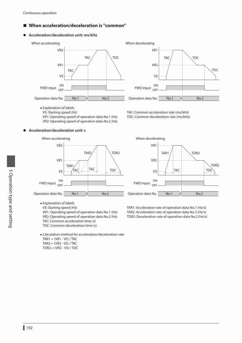
Continuous operation
5 Operation type and setting
192
When acceleration/deceleration is "common"
z Acceleration/deceleration unit: ms/kHz
VR2
VR1
VS
TAC
No.1
OFFON
No.2
FWD input
Operation data No. No.1
OFFON
No.2
FWD input
Operation data No.
When accelerating When decelerating
TAC TDC
VR2
VR1
VS
TAC TDC
TDC
• Explanation of labels VS: Starting speed (Hz) VR1: Operating speed of operation data No.1 (Hz) VR2: Operating speed of operation data No.2 (Hz)
TAC: Common acceleration rate (ms/kHz) TDC: Common deceleration rate (ms/kHz)
z Acceleration/deceleration unit: s
VR2
VR1
VS
TAR1TAC TACTAC TDC TDC
No.1
OFFON
No.2
FWD input
Operation data No. No.1
OFFON
No.2
FWD input
Operation data No.
When accelerating When decelerating
TAR2 TDR2
VR2
VR1
VS
TAR1 TDR2
TDR2
• Explanation of labels VS: Starting speed (Hz) VR1: Operating speed of operation data No.1 (Hz) VR2: Operating speed of operation data No.2 (Hz) TAC: Common acceleration time (s) TDC: Common deceleration time (s)
TAR1: Acceleration rate of operation data No.1 (Hz/s) TAR2: Acceleration rate of operation data No.2 (Hz/s) TDR2: Deceleration rate of operation data No.2 (Hz/s)
•Calculation method for acceleration/deceleration rate TAR1 = (VR1 - VS) / TAC TAR2 = (VR2 - VS) / TAC TDR2 = (VR2 - VS) / TDC

Other operation5 O
peration type and setting
193
7 Other operation
7-1 JOG operation
JOG operation is a function to perform positioning operation of the travel amount set in the "JOG travel amount" parameter.When the +JOG signal to ON, JOG operation is in the positive direction.When the −JOG signal to ON, JOG operation is in the negative direction.This function is convenient for fine adjustment of the position.
z Related parameter
MEXE02 tree view Parameter name Description Initial value
Operation
JOG operating speed
Sets the operating speed for JOG operation.
[Setting range] 1 to 1,000,000 Hz
1,000
Acceleration/deceleration rate of JOG
Sets the acceleration/deceleration rate (acceleration/deceleration time) for JOG operation.
[Setting range] 1 to 1,000,000 (1=0.001 ms/kHz or 1=0.001 s)
1,000
JOG starting speedSets the starting speed for JOG operation.
[Setting range] 0 to 1,000,000 Hz
500
JOG travel amountSets the travel amount for JOG operation.
[Setting range] 1 to 8,388,607 step
1
z Operation example
Speed
JOG operating speed
JOG operating speed
+JOG inputOFFON
-JOG inputOFFON
JOG starting speed
JOG starting speedTime
JOG travel amount
JOG travel amount

Other operation
5 Operation type and setting
194
z Operating method
1) Check the READY output is ON.
2) Turn the +JOG input ON.
3) The motor starts positioning operation.
4) Check the READY output has been turned OFF and turn the +JOG input OFF.
5) When the positioning operation is completed, the READY output will be turned ON.
1
2
3
4 5
MOVE output
END output
READY output
Motor operation
JOG travel amount
+JOG inputON
OFF
ONOFF
ONOFF
ONOFF
7-2 Test operation
Test operation is performed using the MEXE02 or OPX-2A. JOG operation and teaching function can be performed.Refer to the "Support software MEXE02 OPERATING MANUAL" when setting with the MEXE02, and p.121 when setting with the OPX-2A.
JOG operationConnection condition or operation status for the motor and driver can be checked using JOG operation.
Example: When performing test operation with the OPX-2A
Less than 1 s 1 s or more
JOG starting speed
Speed
Time
JOG operating speed
1 step 1 step
Key
TeachingThis is a function to move the motor using the MEXE02 or OPX-2A and set the current position as the position (travel amount) of the operation data. When the position (travel amount) is set using teaching function, the "operation mode" will always be the absolute mode. The operating speed, acceleration/deceleration and starting speed of teaching function are same as those of JOG operation.
Perform teaching function when the position origin is set. See p.198 for setting the position origin.

Other operation5 O
peration type and setting
195
7-3 Automatic return operation
When a position deviation occurs by an external force while the motor is in a non-excitation state, the motor can automatically return to the position where the motor last stopped.When the power is turned on and motor is reexcited by turning the C-ON input ON or turning the FREE input OFF, automatic return operation will be executed under the following conditions;
• When the main power is turned on • When the C-ON input is turned from OFF to ON • When the FREE input is turned from ON to OFF
z Related parameter
MEXE02 tree view Parameter name Description Initial value
Operation
Automatic return operation
Sets whether to enable or disable automatic return operation.
[Setting range] 0: Disable 1: Enable
0
Operation speed of automatic return
Sets the operating speed for automatic return operation.
[Setting range] 1 to 1,000,000 Hz
1,000
Acceleration (deceleration) of automatic return
Sets the acceleration/deceleration rate (acceleration/deceleration time) for automatic return operation.
[Setting range] 1 to 1,000,000 (1=0.001 ms/kHz or 1=0.001 s)
1,000
Starting speed of automatic return
Sets the starting speed for automatic return operation.
[Setting range] 0 to 1,000,000 Hz
500
z Example of automatic return operation
ONOFF
C-ON input
Position deviation
Internal speed commandVR
VSTR TR
Position deviation occursdue to external force
VS: Starting speed of automatic returnVR: Operation speed of automatic returnTR: Acceleration (deceleration) of automatic return
• Automatic return operation will not be executed immediately after turning on the DC power supply or executing the configuration command.
• If an alarm generates while the motor is in a non-excitation state, the automatic return operation will not be executed normally.
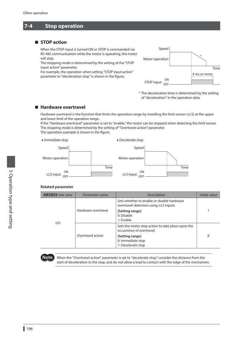
Other operation
5 Operation type and setting
196
7-4 Stop operation
STOP actionWhen the STOP input is turned ON or STOP is commanded via RS-485 communication while the motor is operating, the motor will stop.The stopping mode is determined by the setting of the “STOP input action” parameter.For example, the operation when setting "STOP input action" parameter to "deceleration stop" is shown in the figure.
Speed
Time
*
ONOFF
STOP input
Motor operation
4 ms or more
* The deceleration time is determined by the setting of "deceleration" in the operation data.
Hardware overtravelHardware overtravel is the function that limits the operation range by installing the limit sensor (±LS) at the upper and lower limit of the operation range.If the "Hardware overtravel" parameter is set to "enable," the motor can be stopped when detecting the limit sensor. The stopping mode is determined by the setting of "Overtravel action” parameter.The operation example is shown in the figure.
• Immediate stop
Speed
TimeON
OFF±LS input
Motor operation
•Decelerate stop
Speed
TimeON
OFF±LS input
Motor operation
Related parameter
MEXE02 tree view Parameter name Description Initial value
I/O
Hardware overtravel
Sets whether to enable or disable hardware overtravel detection using ±LS inputs.
[Setting range] 0: Disable 1: Enable
1
Overtravel action
Sets the motor stop action to take place upon the occurrence of overtravel.
[Setting range] 0: Immediate stop 1: Decelerate stop
0
When the "Overtravel action" parameter is set to "decelerate stop," consider the distance from the start of deceleration to the stop, and do not allow a load to contact with the edge of the mechanism.

Other operation5 O
peration type and setting
197
Software overtravelThe software overtravel is a function that limits the range of movement using the parameter.If the "Software overtravel" parameter is set to "enable," the motor can be stopped when exceeding the software limit. The stopping mode is determined by the setting of "Overtravel action” parameter. For example, setting the "Overtravel action" parameter to "decelerate stop" can decelerate the motor according to the deceleration rate and stop it at the software limit.The operation example is shown when an operation where a software limit is to be exceeded is started.
• Immediate stop
Speed
TimeSoftware limit
Motor operation
•Decelerate stop
Speed
TimeSoftware limit
Motor operation
Related parameter
MEXE02 tree view Parameter name Description Initial value
I/O Overtravel action
Sets the motor stop action to take place upon the occurrence of overtravel.
[Setting range] 0: Immediate stop 1: Decelerate stop
0
Coordinates
Software overtravel
Sets whether to enable or disable software overtravel detection using soft limits.
[Setting range] 0: Disable 1: Enable
1
Positive software limitSets the value of soft limit in positive direction.
[Setting range] −8,388,608 to 8,388,607 step
8,388,607
Negative software limitSets the value of soft limit in negative direction.
[Setting range] −8,388,608 to 8,388,607 step
−8,388,608
• Software overtravel will become effective after the position origin is set. See p.198 for setting the position origin.
• When the value of the software limit is changed while the motor is operating, the motor will stop according to the setting of the “Overtravel action” parameter.
Escape from the limit sensorIt is possible to escape in the negative direction when detecting the positive direction limit, and possible to escape in the positive direction when detecting the negative direction limit.The following operations can be used when escaping from the limit sensor.
Types of operation Limit sensors (±LS) Software limit
Positioning operation Will not operate (unable to escape)
Allowed to operate (able to escape)Continuous operation Test operation Return-to-home operation
Allowed to operate (able to escape)

Coordination management
5 Operation type and setting
198
8 Coordination management
8-1 Position coordinate management
The driver manages the motor position information. If the absolute-position backup system is used connecting an accessory battery set, the position information is kept even when the power is turned off.Refer to p.52 (AC power input), p.82 (DC power input) for accessory.
Position origin for the driver
z When the absolute-position backup system is disabledThe position origin will be set whenever one of the following operations is executed:
• Return-to-home operation • P-PRESET input is turned ON
z When the absolute-position backup system is enabledWhen the absolute-position backup system is enabled, once the position origin is set, there is no need to set the position origin again even if the power is turned off. However, if the absolute position error alarm generates, the position origin will be lost. In this case, after clearing the absolute position error alarm by the P-CLR input, set the position origin by executing one of the followings.
• Return-to-home operation • P-PRESET input is turned ON
When the position origin has not been setIf the "Return-to-home incomplete alarm" parameter is set to "enable," positioning operations can be prohibited while the position origin has not been set.The return-to-home incomplete alarm will generate if the START input, SSTART input or the MS0 to MS5 inputs are turned ON while the position origin has not been set. See p.144 for alarm.
Related parameter
MEXE02 tree view Parameter name Description Initial value
AlarmReturn-to-home incomplete alarm
When the positioning operation is started while the position origin has not been set, selects whether the alarm generates or not.
[Setting range] 0: Disable 1: Enable
0

Coordination management5 O
peration type and setting
199
8-2 Wrap function
The wrap function is a function that resets the command position or multi-rotation data to 0 whenever the command position exceeds the set value by the “Wrap setting range” parameter. Since the multi-rotation data is also reset to 0, the unidirectional continuous rotation with the absolute-position backup system will be possible.The command position varies in a range of "0 to (wrap setting value−1)."
Related parameter
MEXE02 tree view Parameter name Description Initial value
Coordinates
Wrap setting
Sets whether to enable or disable wrap function.
[Setting range] 0: Disable 1: Enable
0
Wrap setting rangeSets the wrap setting range.
[Setting range] 1 to 8,388,607 step
1,000
• When setting the "Wrap setting" parameter to "enable," the software overtravel will be disabled. (It is disabled even when setting the "Software overtravel" parameter to "enable.")
• If the "Wrap setting" parameter or "Wrap setting range" parameter is changed while the "Absolute back-up system" parameter is "enable," the absolute position may be lost. Perform return-to-home operation or the P-PRESET when the wrap settings are changed.
Setting condition of wrap function
= An integerCondition 1:Electronic gear B × 1,000
Electronic gear A × 50
= An integerCondition 2: Wrap setting value ×Electronic gear A × 50
Electronic gear B × 1,000
The wrap setting error warning will generate when not meeting these formulas.
When not meeting these formulas while the "Wrap setting" parameter is "enable," the wrap setting error warning will generate. If the power is turned on again or the configuration is executed while the wrap setting error warning is present, the wrap setting error alarm will generate.

Coordination management
5 Operation type and setting
200
Example for wrap functionExample of operation when the positioning operation is performed in the following conditions.
• Wrap setting range : 3,600 • Resolution : 1,000 P/R (electronic gear A=1, electronic gear B=1) • Command position : 900
=1 × 1,000
1 × 50= 20Condition 1:
Electronic gear B × 1,000Electronic gear A × 50
1 × 501 × 1,000
= 3,600 × = 180Condition 2: Wrap setting value ×Electronic gear A × 50
Electronic gear B × 1,000
The calculation result of these two formulas is an integer and this meets the setting condition.Following tables are examples when the positioning operation is performed from 900 steps of the command position.
Operation mode: Incremental Operation mode: AbsolutePosition
0
+1,000 900
1,800
2,700
1,900
0
900
1,800
2,700
1,000
0
-1,000 900
1,800
2,700
3,500 0
900
1,800
2,700
2,600
+5,000
0
900
1,800
2,700
2,300
0
900
1,800
2,700
1,400
0
900
1,800
2,700
3,100
0
900
1,800
2,700
2,200
-5,000

6 Method of control via Modbus RTU (RS-485 communication)
This part explains how to control from the master controller via RS-485 communication. The protocol for the RS-485 communication is the Modbus protocol.
Table of contents
1 Guidance ...............................................202
2 Communication specifications .........208
3 Setting the switches ............................2113-1 Setting the AC power input ......................2113-2 Setting the DC power input ......................213
4 Setting of RS-485 communication ...215
5 Communication mode and communication timing .......................216
5-1 Communication mode ................................2165-2 Communication timing ..............................216
6 Message.................................................2176-1 Query ................................................................2176-2 Response..........................................................219
7 Function code .......................................2217-1 Reading from a holding register(s)
(03h)...................................................................2217-2 Writing to a holding register (06h) .........2227-3 Diagnosis (08h) ..............................................2237-4 Writing to multiple holding registers
(10h)...................................................................224
8 Register address list ............................2268-1 Operation commands .................................2268-2 Maintenance commands ...........................2288-3 Monitor commands .....................................2298-4 Parameter R/W commands .......................232
9 Group send ...........................................244
10 Setting example of the operation ....24610-1 Positioning operation .................................24610-2 Continuous operation .................................24910-3 Return-to-home operation .......................251
11 Detection of communication errors ......................................................253
11-1 Communication errors ................................25311-2 Alarms and warnings ...................................253
12 Timing charts ........................................254

Guidance
6 Method of control via M
odbus RTU (RS-485 com
munication)
202
1 Guidance
If you are new to the AR Series FLEX built-in controller type, read this section to understand the operating methods along with the operation flow.This is an example how to operate the motor based on the operation data and parameters being set to the driver via the master controller.
STEP1 Installation and connection
STEP2 Setting of switches
STEP3 Power-on and check of communication parameters
STEP4 Cycle the power Communication parameters are enabled after the power is cycled.
STEP5 Operate the motor
z Operation condition
Here, the motor is assumed to be operated under the following conditions.
•Number of drivers connected: 1 unit
•Address number: 1
• Transmission rate: 115,200 bps
• Termination resistor: Enable
Before operating the motor, check the condition of the surrounding area to ensure safety.
STEP 1 Check the installation and connection
AC power input
Connect to + and -
Connect to CN2
Main power supply
Cable for motor *
Connect to CN4
24 VDCpower supplyRequired
Required
Communication cablefor the support software *
Master controllerRS-485 communicationcable
Connect to CN6 or CN7
CN1 connector
GroundingGrounding
PC in which the MEXE02has been installed
* Accessory.

Guidance6 M
ethod of control via Modbus RTU
(RS-485 comm
unication)
203
DC power input
Grounding
Grounding
Connect to CN3
Connect to CN1DC power supply
Connect to CN2
Cable for motor *1 *2
Motor cable
Communication cablefor the support software *1
Master controllerRS-485 communicationcable
Connect to CN6 or CN7
PC in which the MEXE02has been installed
*1 Accessory.*2 Use the cable for motor when the length of the motor cable is not enough.
STEP 2 Setting the switches
Set as shown in the table with the switches. The status becomes as shown in the following figures after setting.
AC power input
Setting item Switch Factory setting
Protocol: Modbus protocol Turn No.2 of SW4 ON OFF
Address number: 1 Turn No.1 of SW4 OFF, set ID to 1 No.1 of SW4: OFF, ID: 0
Transmission rate: 115,200 bps Set SW2 to 4 7
Termination resistor: ON Set Nos.1 and 2 of TERM. ON OFF
Address numbersetting switch (ID)
Termination resistor setting switch (TERM.)
Driver front side Driver bottom side
Transmission ratesetting switch (SW2)
Function setting switch (SW4) No.1: Set the address number. No.2: Set the protocol.
No.2: ONNo.1: ON
No.1: OFFNo.2: ON

Guidance
6 Method of control via M
odbus RTU (RS-485 com
munication)
204
DC power input
Setting item Switch Factory setting
Protocol: Modbus protocol Turn No.2 of SW3 ON OFF
Address number: 1 Turn No.1 of SW3 OFF, set SW1 to 1 No.1 of SW3: OFF, SW1: 0
Transmission rate: 115,200 bps Set SW2 to 4 7
Termination resistor: ON Set No.4 of SW3 ON OFF
Transmission ratesetting switch (SW2)
Address numbersetting switch (SW1)
Function setting switch (SW3) No.1: Sets the address number. No.2: Sets the protocol. No.3: Not used. No.4: Sets the termination resistor.
No.1: OFFNo.2: ONNo.3: OFFNo.4: ON
Driver front side Driver bottom side
STEP 3 Turn on the power and check the communication parameters
Check the following communication parameters with the MEXE02.If communication cannot be established, review the communication parameters of the driver.
MEXE02 tree view Parameter name
Communication
•Communication parity [Initial value: 1 (even number)]
•Communication stop bit [Initial value: 0 (1 bit)]
• Transmission waiting time [Initial value: 100 (10.0 ms)]
Set the transmission interval of frames sent from the master to be longer than the silent interval of the driver. When the transmission rate is 115,200 bps, the silent interval of the driver is 2.5 ms.
STEP 4 Cycle the power
The switches of the driver and the communication parameters are enabled after the power is cycled.

Guidance6 M
ethod of control via Modbus RTU
(RS-485 comm
unication)
205
STEP 5 Send a message and operate the motor
As an example, here is a description how to execute the following positioning operation.
8,500 step
2,000 Hz
500 Hz
Speed
Time
1.5 ms/kHz1.5
ms/
kHz
1. Send the following five queries and set the operation data.
•Operation mode of operation data No.0
Field name Data Description
Slave address 01h Slave address 1
Function code 06h Writing to a holding register
Data
Register address (upper) 05hOperation mode No.0 (0501h)
Register address (lower) 01h
Value written (upper) 00hIncremental (0000h)
Value written (lower) 00h
Error check (lower) D8hCalculation result of CRC-16
Error check (upper) C6h
• Position of operation data No.0
Field name Data Description
Slave address 01h Slave address 1
Function code 06h Writing to a holding register
Data
Register address (upper) 04hPosition No.0 (0401h)
Register address (lower) 01h
Value written (upper) 21h8,500 step (2134h)
Value written (lower) 34h
Error check (lower) C0hCalculation result of CRC-16
Error check (upper) BDh
•Operating speed of operation data No.0
Field name Data Description
Slave address 01h Slave address 1
Function code 06h Writing to a holding register
Data
Register address (upper) 04hOperating speed No.0 (0481h)
Register address (lower) 81h
Value written (upper) 07h2,000 Hz (07D0h)
Value written (lower) D0h
Error check (lower) DBhCalculation result of CRC-16
Error check (upper) 7Eh

Guidance
6 Method of control via M
odbus RTU (RS-485 com
munication)
206
•Acceleration of operation data No.0
Field name Data Description
Slave address 01h Slave address 1
Function code 06h Writing to a holding register
Data
Register address (upper) 06hAcceleration No.0 (0601h)
Register address (lower) 01h
Value written (upper) 05h1.5 ms/kHz (05DCh)
Value written (lower) DCh
Error check (lower) DAhCalculation result of CRC-16
Error check (upper) 4Bh
•Deceleration of operation data No.0
Field name Data Description
Slave address 01h Slave address 1
Function code 06h Writing to a holding register
Data
Register address (upper) 06hDeceleration No.0 (0681h)
Register address (lower) 81h
Value written (upper) 05h1.5 ms/kHz (05DCh)
Value written (lower) DCh
Error check (lower) DBhCalculation result of CRC-16
Error check (upper) A3h
2. Send the following two queries and perform operation.
• START input ON (To start operation for operation data No.0)
Field name Data Description
Slave address 01h Slave address 1
Function code 06h Writing to a holding register
Data
Register address (upper) 00hDriver input command (007Dh)
Register address (lower) 7Dh
Value written (upper) 00hSTART ON (0008h)
Value written (lower) 08h
Error check (lower) 18hCalculation result of CRC-16
Error check (upper) 14h
• START input OFF
Field name Data Description
Slave address 01h Slave address1
Function code 06h Writing to a holding register
Data
Register address (upper) 00hDriver input command (007Dh)
Register address (lower) 7Dh
Value written (upper) 00hSTART OFF (0000h)
Value written (lower) 00h
Error check (lower) 19hCalculation result of CRC-16
Error check (upper) D2h
3. Check the motor rotates according to the setting.

Guidance6 M
ethod of control via Modbus RTU
(RS-485 comm
unication)
207
STEP 6 Were you able to operate the motor properly?
How did it go? Were you able to operate the motor properly? If the motor does not function, check the following points:
• Is any alarm present? • Are the power supply, motor and RS-485 communication cable connected securely? • Are the slave address, transmission rate and termination resistor set correctly? • Is the C-DAT/C-ERR LED turned off? Or is it lit in red? (A communication erro has occured.)

Communication specifications
6 Method of control via M
odbus RTU (RS-485 com
munication)
208
2 Communication specifications
Electrical characteristicsIn conformance with EIA-485, straight cable Use a twisted pair cable (TIA/EIA-568B CAT5e or higher is recommended) and keep the total wiring distance including extension to 50 m (164 ft.) or less. *
Communication modeHalf duplex Asynchronous mode (data: 8 bits, stop bit: 1 bit/2 bits, parity: none/even number/odd number)
Transmission rate Selectable from 9,600 bps, 19,200 bps, 38,400 bps, 57,600 bps and 115,200 bps.
Protocol Modbus RTU mode
Connection figure Up to 31 drivers can be connected to one master controller.
* If the motor cable or power supply cable generates an undesirable amount of noise depending on the wiring or configuration, shield the cable or install a ferrite core.
Connection exampleThe figure shows the model for AC power input.
Master controller
RS-485Terminationresistor
Termination resistor(TERM.-No.1/No.2): ON
Address number 2 Address number 31Address number 1

Communication specifications6 M
ethod of control via Modbus RTU
(RS-485 comm
unication)
209
Internal circuit diagram
z AC power input
Driver 1
0 V
RS-485
*1GND
TR+TR-
GND
TR+
TR-120 Ω
1 kΩ
1 kΩ
5 V
0 V
0 V
TERM.No.2
TERM.No.1
Driver 2
GND
TR+TR-
GND
TR+
TR-120 Ω
1 kΩ
1 kΩ
5 V
0 V
0 V
TERM.No.2
TERM.No.1
Driver 31
GND
TR+TR-
120 Ω
1 kΩ
1 kΩ
5 V
0 V
0 V
TERM.No.2 *2
TERM.No.1 *2
*1 Termination resistor 120 Ω*2 Turn the termination resistor ON (TERM.-Nos.1 and 2).

Communication specifications
6 Method of control via M
odbus RTU (RS-485 com
munication)
210
z DC power input
TR+TR-
GNDTR+TR-
GND
TR+TR-
GND
TR+TR-
GND
TR+TR-
GND
120 Ω
0 V *30 V
SW3-No.4
Driver 1RS-485
*1
120 Ω
0 V *3
SW3-No.4
Driver 2
120 Ω
0 V *3
SW3-No.4 *2
Driver 31
*1 Termination resistor 120 Ω*2 Turn the termination resistor ON (SW3-No.4).*3 Common with GND of CN1 (Non-isolated)

Setting the switches6 M
ethod of control via Modbus RTU
(RS-485 comm
unication)
211
3 Setting the switches
Switches differ in the AC power input driver and the DC power input driver. Set properly.
3-1 Setting the AC power input
The figures show the status of factory setting.
Address numbersetting switch (ID)
Termination resistor setting switch (TERM.)
Driver front side Driver bottom side
Transmission ratesetting switch (SW2)
Function setting switch (SW4) No.1: Sets the address number. No.2: Sets the protocol.
No.2: OFFNo.1: OFF
No.1: OFFNo.2: OFF
Be sure to turn off the control power supply of the driver before setting the switches. If the switches are set while the power is still on, the new switch settings will not become effective until the control power supply of the driver is cycled.
ProtocolSet the SW4-No.2 of the function setting switch to ON. The Modbus protocol is selected.
Factory setting OFF
SW4-No.2 Protocol
ON Modbus RTU protocol
OFF Connect to the network converter
Transmission rateUsing transmission rate setting switch (SW2), set the transmission rate .The transmission rate to be set should be the same as the transmission rate of the master controller.
Factory setting 7
SW2 Transmission rate (bps)
0 9,600
1 19,200
2 38,400
3 57,600
4 115,200
5 to F Not used
Do not set SW2 to positions 5 to F.

Setting the switches
6 Method of control via M
odbus RTU (RS-485 com
munication)
212
Address number (slave address)Using the address number setting switch (ID) and SW4-No.1 of the function setting switch, set the address number (slave address). Make sure each address number (slave address) you set for each driver is unique.Address number (slave address) 0 is reserved for broadcasting, so do not use this address.
Factory setting ID: 0, SW4-No.1: OFF
ID SW4-No.1Address number (slave address)
ID SW4-No.1Address number (slave address)
0
OFF
Not used 0
ON
16
1 1 1 17
2 2 2 18
3 3 3 19
4 4 4 20
5 5 5 21
6 6 6 22
7 7 7 23
8 8 8 24
9 9 9 25
A 10 A 26
B 11 B 27
C 12 C 28
D 13 D 29
E 14 E 30
F 15 F 31
Termination resistorSet a termination resistor (120 Ω) of RS-485 communication for the driver located farthest away (positioned at the end) from the master controller.Turn the termination resistor setting switch (TERM.-Nos.1 and 2) ON to set the termination resistor for RS-485 communication (120 Ω).
Factory setting Nos.1 and 2: Both OFF (termination resistor disabled)
TERM.-Nos.1 and 2 Termination resistor (120 Ω)
Both are OFF Disabled
Both are ON Enabled
If only one of No.1 or No.2 is turned ON, a communication error may occur.
2 GND3 TR+
6 TR-
2 GND3 TR+
6 TR-120 Ω
1 kΩ
1 kΩ
5 V
0 V0 V
TERM.No.2
TERM.No.1
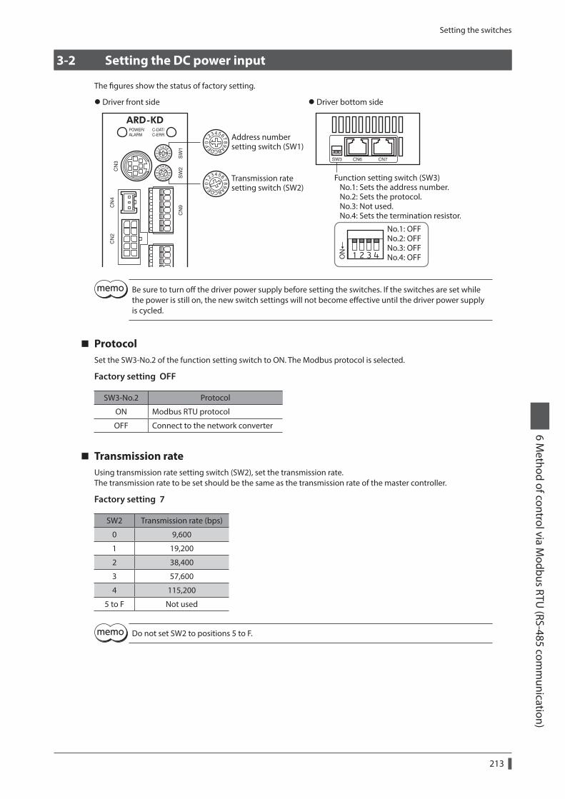
Setting the switches6 M
ethod of control via Modbus RTU
(RS-485 comm
unication)
213
3-2 Setting the DC power input
The figures show the status of factory setting.
No.1: OFFNo.2: OFFNo.3: OFFNo.4: OFF
Transmission ratesetting switch (SW2)
Address numbersetting switch (SW1)
Function setting switch (SW3) No.1: Sets the address number. No.2: Sets the protocol. No.3: Not used. No.4: Sets the termination resistor.
Driver front side Driver bottom side
Be sure to turn off the driver power supply before setting the switches. If the switches are set while the power is still on, the new switch settings will not become effective until the driver power supply is cycled.
ProtocolSet the SW3-No.2 of the function setting switch to ON. The Modbus protocol is selected.
Factory setting OFF
SW3-No.2 Protocol
ON Modbus RTU protocol
OFF Connect to the network converter
Transmission rateUsing transmission rate setting switch (SW2), set the transmission rate.The transmission rate to be set should be the same as the transmission rate of the master controller.
Factory setting 7
SW2 Transmission rate (bps)
0 9,600
1 19,200
2 38,400
3 57,600
4 115,200
5 to F Not used
Do not set SW2 to positions 5 to F.
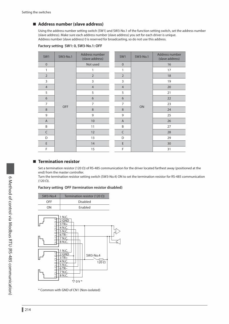
Setting the switches
6 Method of control via M
odbus RTU (RS-485 com
munication)
214
Address number (slave address)Using the address number setting switch (SW1) and SW3-No.1 of the function setting switch, set the address number (slave address). Make sure each address number (slave address) you set for each driver is unique.Address number (slave address) 0 is reserved for broadcasting, so do not use this address.
Factory setting SW1: 0, SW3-No.1: OFF
SW1 SW3-No.1Address number (slave address)
SW1 SW3-No.1Address number (slave address)
0
OFF
Not used 0
ON
16
1 1 1 17
2 2 2 18
3 3 3 19
4 4 4 20
5 5 5 21
6 6 6 22
7 7 7 23
8 8 8 24
9 9 9 25
A 10 A 26
B 11 B 27
C 12 C 28
D 13 D 29
E 14 E 30
F 15 F 31
Termination resistorSet a termination resistor (120 Ω) of RS-485 communication for the driver located farthest away (positioned at the end) from the master controller.Turn the termination resistor setting switch (SW3-No.4) ON to set the termination resistor for RS-485 communication (120 Ω).
Factory setting OFF (termination resistor disabled)
SW3-No.4 Termination resistor (120 Ω)
OFF Disabled
ON Enabled
1 N.C.2 GND3 TR+4 N.C.5 N.C.6 TR-7 N.C.8 N.C.
1 N.C.2 GND3 TR+4 N.C.5 N.C.6 TR-7 N.C.8 N.C.
120 Ω
0 V *
SW3-No.4
* Common with GND of CN1 (Non-isolated)

Setting of RS-485 communication6 M
ethod of control via Modbus RTU
(RS-485 comm
unication)
215
4 Setting of RS-485 communication
Set parameters required RS-485 communication first.When a parameter is changed, the timing to update the new value varies depending on the parameter. Refer to “Communication parameter” on p.120 for the timing to update each parameter.
Parameters set with the MEXE02 or OPX-2ASet the following parameters using the MEXE02 or OPX-2A since they cannot be set via RS-485 communication.
MEXE02 tree view Parameter name Description Initial value
Communication
Communication parity
Sets the parity of RS-485 communication.
[Setting range] 0: None 1: Even 2: Odd
1
Communication stop bit
Sets the stop bit of RS-485 communication.
[Setting range] 0: 1 bit 1: 2 bits
0
Transmission waiting time
Sets the transmission waiting time of RS-485 communication.
[Setting range] 0 to 10,000 (1=0.1 ms)
100
Parameters set with the MEXE02, OPX-2A or via RS-485 communicationSet the following parameters using the MEXE02, OPX-2A or via RS-485 communication.
MEXE02 tree view Parameter name Description Initial value
Communication
Communication timeout
Sets the condition in which a communication timeout occurs in RS-485 communication. It is not monitored when the set value is 0.
[Setting range] 0: Not monitored 1 to 10,000 ms
0
Communication error alarm
Sets the condition in which a RS-485 communication error alarm generates. A communication error alarm generates after a RS-485 communication error has occurred by the number of times set here.
[Setting range] 1 to 10 times
3
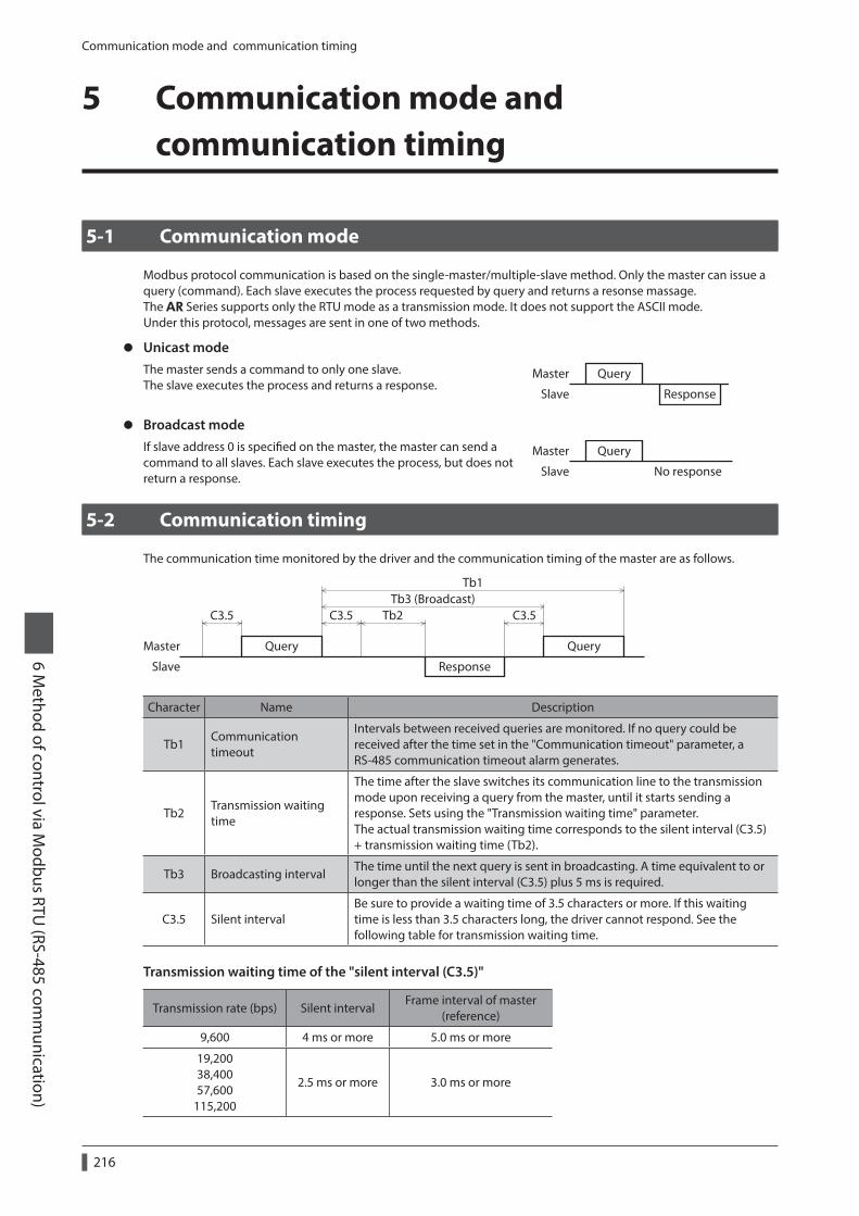
Communication mode and communication timing
6 Method of control via M
odbus RTU (RS-485 com
munication)
216
5 Communication mode and communication timing
5-1 Communication mode
Modbus protocol communication is based on the single-master/multiple-slave method. Only the master can issue a query (command). Each slave executes the process requested by query and returns a resonse massage.The AR Series supports only the RTU mode as a transmission mode. It does not support the ASCII mode.Under this protocol, messages are sent in one of two methods.
z Unicast modeThe master sends a command to only one slave.The slave executes the process and returns a response.
Query
Response
Master
Slave
z Broadcast modeIf slave address 0 is specified on the master, the master can send a command to all slaves. Each slave executes the process, but does not return a response.
Master
Slave No response
Query
5-2 Communication timing
The communication time monitored by the driver and the communication timing of the master are as follows.
Query
Tb2 C3.5C3.5C3.5Tb3 (Broadcast)
Tb1
Query
Response
Master
Slave
Character Name Description
Tb1Communication timeout
Intervals between received queries are monitored. If no query could be received after the time set in the "Communication timeout" parameter, a RS-485 communication timeout alarm generates.
Tb2Transmission waiting time
The time after the slave switches its communication line to the transmission mode upon receiving a query from the master, until it starts sending a response. Sets using the "Transmission waiting time" parameter. The actual transmission waiting time corresponds to the silent interval (C3.5) + transmission waiting time (Tb2).
Tb3 Broadcasting intervalThe time until the next query is sent in broadcasting. A time equivalent to or longer than the silent interval (C3.5) plus 5 ms is required.
C3.5 Silent intervalBe sure to provide a waiting time of 3.5 characters or more. If this waiting time is less than 3.5 characters long, the driver cannot respond. See the following table for transmission waiting time.
Transmission waiting time of the "silent interval (C3.5)"
Transmission rate (bps) Silent intervalFrame interval of master
(reference)
9,600 4 ms or more 5.0 ms or more
19,200 38,400 57,600
115,200
2.5 ms or more 3.0 ms or more

Message6 M
ethod of control via Modbus RTU
(RS-485 comm
unication)
217
6 Message
The message format is shown below.
Master Query SlaveSlave address Slave address
Function code Response Function code
Data Data
Error check Error check
6-1 Query
The query message structure is shown below.
Slave address Function code Data Error check
8 bits 8 bits N×8 bits 16 bits
Slave addressSpecify the slave address (unicast mode).If the slave address is set to 0, the master can send a query to all slaves (broadcast mode).
Function codeThe function codes and message lengths supported by the driver are as follows.
Function code FunctionMessage length
BroadcastQuery Response
03h Reading from a holding register(s) 8 7 to 37 Impossible
06h Writing to a holding register 8 8 Possible
08h Diagnosis 8 8 Impossible
10h Writing to multiple holding registers 11 to 41 8 Possible
DataSet data associated with the selected function code. The specific data length varies depending on the function code.
Error checkIn the Modbus RTU mode, error checks are based on the CRC-16 method. The slave calculates a CRC-16 of each received message and compares the result against the error check value included in the message. If the calculated CRC-16 value matches the error check value, the slave determines that the message is normal.
z CRC-16 calculation method
1. Calculate an exclusive-OR (XOR) value of the default value of FFFFh and slave address (8 bits).
2. Shift the result of step 1 to the right by 1 bit. Repeat this shift until the overflow bit becomes "1."
3. Upon obtaining "1" as the overflow bit, calculate an XOR of the result of step 2 and A001h.
4. Repeat steps 2 and 3 until a shift is performed eight times.
5. Calculate an XOR of the result of step 4 and function code (8 bits).Repeat steps 2 to 4 for all bytes.The final result gives the result of CRC-16 calculation.

Message
6 Method of control via M
odbus RTU (RS-485 com
munication)
218
z Example of CRC-16 calculationThe table is a calculation example when setting the slave address of the first byte to 02h and setting the function code of the second byte to 07h.The result of actual CRC-16 calculation is calculated including the data on and after the third byte.
Description Result Overflow digit
Default value in CRC register FFFFh 1111 1111 1111 1111 −
First byte 02h 0000 0000 0000 0010 −
XOR with default value FFFFh 1111 1111 1111 1101 −
First shift to right 0111 1111 1111 1110 1
XOR with A001h1010 0000 0000 0001 1101 1111 1111 1111
−
Second shift to right 0110 1111 1111 1111 1
XOR with A001h1010 0000 0000 0001 1100 1111 1111 1110
−
Third shift to right 0110 0111 1111 1111 0
Fourth shift to right 0011 0011 1111 1111 1
XOR with A001h1010 0000 0000 0001 1001 0011 1111 1110
−
Fifth shift to right 0100 1001 1111 1111 0
Sixth shift to right 0010 0100 1111 1111 1
XOR with A001h1010 0000 0000 0001 1000 0100 1111 1110
−
Seventh shift to right 0100 0010 0111 1111 0
Eighth shift to right 0010 0001 0011 1111 1
XOR with A001h1010 0000 0000 0001 1000 0001 0011 1110
−
XOR with next byte 07h0000 0000 0000 0111 1000 0001 0011 1001
−
First shift to right 0100 0000 1001 1100 1
XOR with A001h1010 0000 0000 0001 1110 0000 1001 1101
−
Second shift to right 0111 0000 0100 1110 1
XOR with A001h1010 0000 0000 0001 1101 0000 0100 1111
−
Third shift to right 0110 1000 0010 0111 1
XOR with A001h1010 0000 0000 0001 1100 1000 0010 0110
−
Fourth shift to right 0110 0100 0001 0011 0
Fifth shift to right 0011 0010 0000 1001 1
XOR with A001h1010 0000 0000 0001 1001 0010 0000 1000
−
Sixth shift to right 0100 1001 0000 0100 0
Seventh shift to right 0010 0100 1000 0010 0
Eighth shift to right 0001 0010 0100 0001 0
Result of CRC-16 0001 0010 0100 0001 −

Message6 M
ethod of control via Modbus RTU
(RS-485 comm
unication)
219
6-2 Response
Slave-returned responses are classified into three types: normal response, no response, and exception response.The response message structure is the same as the query message structure.
Slave address Function code Data Error check
8 bits 8 bits N×8 bits 16 bits
Normal responseUpon receiving a query from the master, the slave executes the requested process and returns a response corresponding th the function code.
No responseThe slave may not return a response to a query sent by the master. This condition is referred to as "No response."The causes of no response are explained below.
z Transmission errorThe slave discards the query and does not return a response if any of the following transmission errors is detected.
Cause of transmission error Description
Framing error Stop bit 0 was detected.
Parity error A mismatch with the specified parity was detected.
Mismatched CRC The calculated value of CRC-16 was found not matching the error check value.
Invalid message length The message length exceeded 256 bytes.
z Other than transmission errorA response may not be returned without any transmission error being detected.
Cause Description
BroadcastIf the query was broadcast, the slave executes the requested process but does not return a response.
Mismatched slave address
The slave address in the query was found not matching the slave address of the driver.
Exception responseAn exception response is returned if the slave cannot execute the process requested by the query. Appended to this response is an exception code indicating why the process cannot be executed. The message structure of exception response is as follows.
Slave address Function code Exception code Error check
8 bits 8 bits 8 bits 16 bits
z Function codeThe function code in the exception response is a sum of the function code in the query and 80h.
Function code of query Exception response
03h 83h
06h 86h
08h 88h
10h 90h
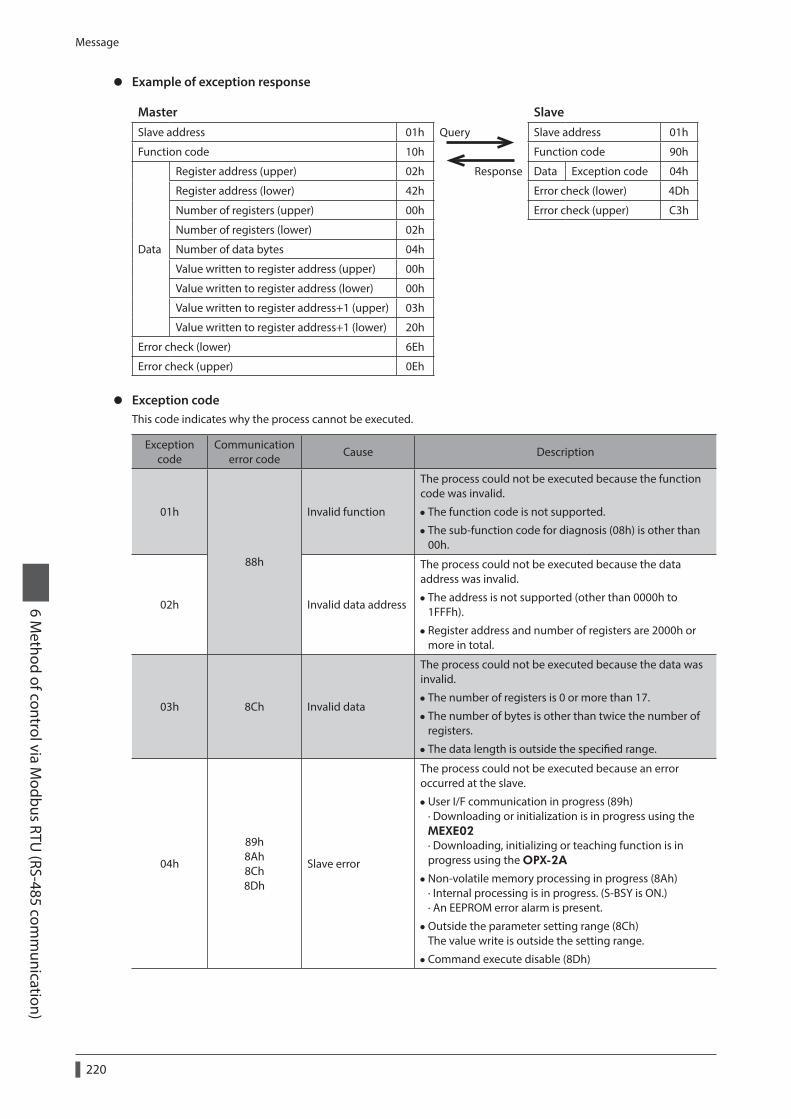
Message
6 Method of control via M
odbus RTU (RS-485 com
munication)
220
z Example of exception response
Master SlaveSlave address 01h Query Slave address 01h
Function code 10h Function code 90h
Data
Register address (upper) 02h Response Data Exception code 04h
Register address (lower) 42h Error check (lower) 4Dh
Number of registers (upper) 00h Error check (upper) C3h
Number of registers (lower) 02h
Number of data bytes 04h
Value written to register address (upper) 00h
Value written to register address (lower) 00h
Value written to register address+1 (upper) 03h
Value written to register address+1 (lower) 20h
Error check (lower) 6Eh
Error check (upper) 0Eh
z Exception codeThis code indicates why the process cannot be executed.
Exception code
Communication error code
Cause Description
01h
88h
Invalid function
The process could not be executed because the function code was invalid.
• The function code is not supported.
• The sub-function code for diagnosis (08h) is other than 00h.
02h Invalid data address
The process could not be executed because the data address was invalid.
• The address is not supported (other than 0000h to 1FFFh).
• Register address and number of registers are 2000h or more in total.
03h 8Ch Invalid data
The process could not be executed because the data was invalid.
• The number of registers is 0 or more than 17.
• The number of bytes is other than twice the number of registers.
• The data length is outside the specified range.
04h
89h 8Ah 8Ch 8Dh
Slave error
The process could not be executed because an error occurred at the slave.
•User I/F communication in progress (89h) · Downloading or initialization is in progress using the MEXE02 · Downloading, initializing or teaching function is in progress using the OPX-2A
•Non-volatile memory processing in progress (8Ah) · Internal processing is in progress. (S-BSY is ON.) · An EEPROM error alarm is present.
•Outside the parameter setting range (8Ch) The value write is outside the setting range.
•Command execute disable (8Dh)

Function code6 M
ethod of control via Modbus RTU
(RS-485 comm
unication)
221
7 Function code
This chapter explains the function codes supported by the AR Series drivers.Note that the function code cannot be executed if function codes other than those introduced here are sent.
7-1 Reading from a holding register(s) (03h)
This function code is used to read a register (16 bits). Up to 16 successive registers (16×16 bits) can be read.Read the upper and lower data at the same time. If they are not read at the same time, the value may be invalid.If multiple holding registers are read, they are read in order of register addresses.
Example of readRead operation data for positions Nos.1 and 2 of slave address 1.
Description Register address Value read Corresponding decimal
Operation data position No.1 (upper) 0402h 0000h10,000
Operation data position No.1 (lower) 0403h 2710h
Operation data position No.2 (upper) 0404h FFFFh−10,000
Operation data position No.2 (lower) 0405h D8F0h
z Query
Field name Data Description
Slave address 01h Slave address1
Function code 03h Reading from holding registers
Data
Register address (upper) 04hRegister address to start reading from
Register address (lower) 02h
Number of registers (upper) 00h Number of registers to be read from the starting register address (4 registers=0004h)Number of registers (lower) 04h
Error check (lower) E4hCalculation result of CRC-16
Error check (upper) F9h
z Response
Field name Data Description
Slave address 01h Same as query
Function code 03h Same as query
Data
Number of data bytes 08h Twice the number of registers in the query
Value read from register address (upper) 00hValue read from register address 0402h
Value read from register address (lower) 00h
Value read from register address+1 (upper) 27hValue read from register address 0403h
Value read from register address+1 (lower) 10h
Value read from register address+2 (upper) FFhValue read from register address 0404h
Value read from register address+2 (lower) FFh
Value read from register address+3 (upper) D8hValue read from register address 0405h
Value read from register address+3 (lower) F0h
Error check (lower) 08hCalculation result of CRC-16
Error check (upper) A3h

Function code
6 Method of control via M
odbus RTU (RS-485 com
munication)
222
7-2 Writing to a holding register (06h)
This function code is used to write data to a specified register address.However, since the result combining the upper and lower may be outside the data range, write the upper and lower at the same time using the "Writing to multiple holding registers (10h)."
Example of writeWrite 80 (50h) as speed filter to slave address 2.
Description Register address Value written Corresponding decimal
Speed filter 024Bh 50h 80
z Query
Field name Data Description
Slave address 02h Slave address 2
Function code 06h Writing to a holding register
Data
Register address (upper) 02hRegister address to be written
Register address (lower) 4Bh
Value written (upper) 00hValue written to the register address
Value written (lower) 50h
Error check (lower) F8hCalculation result of CRC-16
Error check (upper) 6Bh
z Response
Field name Data Description
Slave address 02h Same as query
Function code 06h Same as query
Data
Register address (upper) 02hSame as query
Register address (lower) 4Bh
Value written (upper) 00hSame as query
Value written (lower) 50h
Error check (lower) F8hCalculation result of CRC-16
Error check (upper) 6Bh

Function code6 M
ethod of control via Modbus RTU
(RS-485 comm
unication)
223
7-3 Diagnosis (08h)
This function code is used to diagnose the communication between the master and slave. Arbitrary data is sent and the returned data is used to determine whether the communication is normal. 00h (reply to query) is the only sub-function supported by this function code.
Example of diagnosisSend arbitrary data (1234h) to the slave.
z Query
Field name Data Description
Slave address 03h Slave address 3
Function code 08h Diagnosis
Data
Sub-function code (upper) 00hReturn the query data
Sub-function code (lower) 00h
Data value (upper) 12hArbitrary data (1234h)
Data value (lower) 34h
Error check (lower) EChCalculation result of CRC-16
Error check (upper) 9Eh
z Response
Field name Data Description
Slave address 03h Same as query
Function code 08h Same as query
Data
Sub-function code (upper) 00hSame as query
Sub-function code (lower) 00h
Data value (upper) 12hSame as query
Data value (lower) 34h
Error check (lower) EChSame as query
Error check (upper) 9Eh

Function code
6 Method of control via M
odbus RTU (RS-485 com
munication)
224
7-4 Writing to multiple holding registers (10h)
This function code is used to write data to multiple successive registers. Up to 16 registers can be written.Write the data to the upper and lower at the same time. If not, an invalid value may be written.Registers are written in order of register addresses. Note that even when an exception response is returned because some data is invalid as being outside the specified range, etc., other data may have been written properly.
Example of writeSet the following data as acceleration Nos.2 to 4 as part of operation data at slave address 4.
Description Register address Value written Corresponding decimal
Operation data acceleration No.2 (upper) 0604h 0000h10,000
Operation data acceleration No.2 (lower) 0605h 2710h
Operation data acceleration No.3 (upper) 0606h 0000h20,000
Operation data acceleration No.3 (lower) 0607h 4E20h
Operation data acceleration No.4 (upper) 0608h 0007h500,000
Operation data acceleration No.4 (lower) 0609h A120h
z Query
Field name Data Description
Slave address 04h Slave address 4
Function code 10h Writing to multiple holding registers
Data
Register address (upper) 06hRegister address to start writing from
Register address (lower) 04h
Number of registers (upper) 00h Number of registers to be written from the starting register address (6 registers=0006h)Number of registers (lower) 06h
Number of data bytes 0ChTwice the number of registers in the command
Value written to register address (upper) 00hValue written to register address 0604h
Value written to register address (lower) 00h
Value written to register address+1 (upper) 27hValue written to register address 0605h
Value written to register address+1 (lower) 10h
Value written to register address+2 (upper) 00hValue written to register address 0606h
Value written to register address+2 (lower) 00h
Value written to register address+3 (upper) 4EhValue written to register address 0607h
Value written to register address+3 (lower) 20h
Value written to register address+4 (upper) 00hValue written to register address 0608h
Value written to register address+4 (lower) 07h
Value written to register address+5 (upper) A1hValue written to register address 0609h
Value written to register address+5 (lower) 20h
Error check (lower) 1DhCalculation result of CRC-16
Error check (upper) A9h

Function code6 M
ethod of control via Modbus RTU
(RS-485 comm
unication)
225
z Response
Field name Data Description
Slave address 04h Same as query
Function code 10h Same as query
Data
Register address (upper) 06hSame as query
Register address (lower) 04h
Number of registers (upper) 00hSame as query
Number of registers (lower) 06h
Error check (lower) 01hCalculation result of CRC-16
Error check (upper) 17h

Register address list
6 Method of control via M
odbus RTU (RS-485 com
munication)
226
8 Register address list
All data used by the driver is 32-bit wide. Since the register for the Modbus protocol is 16-bit wide, one data is described by two registers.Since the address assignment is big endian, the even number addresses become the upper and the odd number addresses become the lower.
8-1 Operation commands
Commands related to motor operation. Operation commands are not saved in the non-volatile memory.
Register addressName Description
READ/WRITE
Setting rangeDec Hex
48 0030h Group (upper) Sets the address number for the group send.
R/W
−1 : No group specification (Group send is not performed) 1 to 31 : Sets a group address (Address number of parent slave).49 0031h Group (lower)
124 007ChDriver input command (upper) Sets the input
command to the driver.R/W
Refer to “Driver input command (007Ch/007Dh)” on p.227.
125 007DhDriver input command (lower)
126 007EhDriver output command (upper) Reads the output status
of the driver.R
Refer to “Driver output command (007Eh/007Fh)” on p.227.
127 007FhDriver output command (lower)
Group (0030h/0031h)Multiple slaves are made into a group and a query is sent to all slaves in the group at once. See p.244 for group details. The initial value is −1. When setting a group, read/write to the upper and lower at the same time.
Address (Hex) Description of address *
0030h
Bit15 Bit14 Bit13 Bit12 Bit11 Bit10 Bit9 Bit8
[FFFFh]
Bit7 Bit6 Bit5 Bit4 Bit3 Bit2 Bit1 Bit0
[FFFFh]
* [ ]: Initial value
Address (Hex) Description of address *
0031h
Bit15 Bit14 Bit13 Bit12 Bit11 Bit10 Bit9 Bit8
1 to 31: Sets a group address. [FFFFh]
Bit7 Bit6 Bit5 Bit4 Bit3 Bit2 Bit1 Bit0
1 to 31: Sets a group address. [FFFFh]
* [ ]: Initial value

Register address list6 M
ethod of control via Modbus RTU
(RS-485 comm
unication)
227
Driver input command (007Ch/007Dh)These are the driver input signals that can be accessed via RS-485 communication. See p.92 for each input signal.
Address (Hex) Description of address
007Ch
Bit15 Bit14 Bit13 Bit12 Bit11 Bit10 Bit9 Bit8
− − − − − − − −
Bit7 Bit6 Bit5 Bit4 Bit3 Bit2 Bit1 Bit0
− − − − − − − −
Address (Hex) Description of address *
007Dh
Bit15 Bit14 Bit13 Bit12 Bit11 Bit10 Bit9 Bit8
NET-IN15 [RVS]
NET-IN14 [FWD]
NET-IN13 [−JOG]
NET-IN12 [+JOG]
NET-IN11 [SSTART]
NET-IN10 [MS2]
NET-IN9 [MS1]
NET-IN8 [MS0]
Bit7 Bit6 Bit5 Bit4 Bit3 Bit2 Bit1 Bit0
NET-IN7 [not used]
NET-IN6 [FREE]
NET-IN5 [STOP]
NET-IN4 [HOME]
NET-IN3 [START]
NET-IN2 [M2]
NET-IN1 [M1]
NET-IN0 [M0]
* [ ]: Initial value
Driver output command (007Eh/007Fh)These are the driver output signals that can be received via RS-485 communication. See p.98 for each output signal.
Address (Hex)
Description of address
007Eh
Bit15 Bit14 Bit13 Bit12 Bit11 Bit10 Bit9 Bit8
− − − − − − − −
Bit7 Bit6 Bit5 Bit4 Bit3 Bit2 Bit1 Bit0
− − − − − − − −
Address (Hex)
Description of address *
007Fh
Bit15 Bit14 Bit13 Bit12 Bit11 Bit10 Bit9 Bit8
NET-OUT15 [TLC]
NET-OUT14 [END]
NET-OUT13 [MOVE]
NET-OUT12 [TIM]
NET-OUT11 [AREA3]
NET-OUT10 [AREA2]
NET-OUT9 [AREA1]
NET-OUT8 [S-BSY]
Bit7 Bit6 Bit5 Bit4 Bit3 Bit2 Bit1 Bit0
NET-OUT7 [ALM]
NET-OUT6 [WNG]
NET-OUT5 [READY]
NET-OUT4 [HOME-P]
NET-OUT3 [START_R]
NET-OUT2 [M2_R]
NET-OUT1 [M1_R]
NET-OUT0 [M0_R]
* [ ]: Initial value

Register address list
6 Method of control via M
odbus RTU (RS-485 com
munication)
228
8-2 Maintenance commands
These commands are used to reset alarms and warnings. They are also used to execute the batch processing for the non-volatile memory. All commands can be written (WRITE). Executes when writing from 0 to 1.
Register addressName Description
Setting rangeDec Hex
384 0180h Reset alarm (upper) Resets the alarms that are present. Some alarms cannot be reset with the “reset alarm.”
0, 1
385 0181h Reset alarm (lower)
386 0182hAbsolute position error alarm reset (upper)
Resets the absolute position error alarm.387 0183h
Absolute position error alarm reset (lower)
388 0184h Clear alarm records (upper)Clears alarm records.
389 0185h Clear alarm records (lower)
390 0186h Clear warning records (upper)Clears warning records.
391 0187h Clear warning records (lower)
392 0188hClear communication error records (upper)
Clears the communication error records.393 0189h
Clear communication error records (lower)
394 018Ah P-PRESET execute (upper)Presets the command position.
395 018Bh P-PRESET execute (lower)
396 018Ch Configuration (upper)Executes the parameter recalculation and the setup.
397 018Dh Configuration (lower)
398 018Eh All data initialization (upper) * Resets the operation data and parameters saved in the non-volatile memory, to their defaults.399 018Fh All data initialization (lower) *
400 0190hBatch non-volatile memory read (upper)
Reads the parameters saved in the non-volatile memory, to the RAM. All operation data and parameters previously saved in the RAM are overwritten.401 0191h
Batch non-volatile memory read (lower)
402 0192hBatch non-volatile memory write (upper) Writes the parameters saved in the RAM to the non-
volatile memory. The non-volatile memory can be rewritten approximately 100,000 times.403 0193h
Batch non-volatile memory write (lower)
* Communication parity, communication stop bit and transmission waiting time are not initialized. Initialize them using the MEXE02 or OPX-2A.

Register address list6 M
ethod of control via Modbus RTU
(RS-485 comm
unication)
229
Configuration (018Ch/018Dh)Configuration will be executed when all of the following conditions are satisfied:
• An alarm is not present. • The motor is not operated. • The MEXE02 is in other status than downloading, I/O test, test operation or teaching function. • The OPX-2A is in other modes than the test mode or copy mode.
Shows the driver status before and after executing the configuration.
ItemConfiguration is ready to
executeConfiguration is
executingConfiguration is
completed
AC power input: PWR LED DC power input: POWER LED
Lit Lit
Based on the driver condition.
AC power input: ALM LED DC power input: ALARM LED
OFF OFF
Electromagnetic brake Hold/Release Hold
Motor excitation Excitation/no excitation No excitation
Output signals
Allowed
Indeterminate
AllowedInput signalsNot allowed
Sensor inputs
• The correct monitor value may not return even when the monitor is executed while executing the configuration.
• If the "Automatic return action" parameter is "enable" while meeting the conditions performing the automatic return operation, the automatic return operation will not perform immediately after executing the configuration.
8-3 Monitor commands
These commands are used to monitor the command position, command speed, alarm and warning records, etc. All commands can be read (READ).
Register addressName Description Setting range
Dec Hex
128 0080h Present alarm (upper)Monitors the present alarm code.
00h to FFh
129 0081h Present alarm (lower)
130 0082h Alarm record 1 (upper)
Monitors the alarm records.
131 0083h Alarm record 1 (lower)
132 0084h Alarm record 2 (upper)
133 0085h Alarm record 2 (lower)
134 0086h Alarm record 3 (upper)
135 0087h Alarm record 3 (lower)
136 0088h Alarm record 4 (upper)
137 0089h Alarm record 4 (lower)
138 008Ah Alarm record 5 (upper)
139 008Bh Alarm record 5 (lower)
140 008Ch Alarm record 6 (upper)
141 008Dh Alarm record 6 (lower)
142 008Eh Alarm record 7 (upper)
143 008Fh Alarm record 7 (lower)
144 0090h Alarm record 8 (upper)
145 0091h Alarm record 8 (lower)
146 0092h Alarm record 9 (upper)
147 0093h Alarm record 9 (lower)

Register address list
6 Method of control via M
odbus RTU (RS-485 com
munication)
230
Register addressName Description Setting range
Dec Hex
148 0094h Alarm record 10 (upper)Monitors the alarm records.
00h to FFh
149 0095h Alarm record 10 (lower)
150 0096h Present warning (upper)Monitors the present warning code.
151 0097h Present warning (lower)
152 0098h Warning record 1 (upper)
Monitors the warning records.
153 0099h Warning record 1 (lower)
154 009Ah Warning record 2 (upper)
155 009Bh Warning record 2 (lower)
156 009Ch Warning record 3 (upper)
157 009Dh Warning record 3 (lower)
158 009Eh Warning record 4 (upper)
159 009Fh Warning record 4 (lower)
160 00A0h Warning record 5 (upper)
161 00A1h Warning record 5 (lower)
162 00A2h Warning record 6 (upper)
163 00A3h Warning record 6 (lower)
164 00A4h Warning record 7 (upper)
165 00A5h Warning record 7 (lower)
166 00A6h Warning record 8 (upper)
167 00A7h Warning record 8 (lower)
168 00A8h Warning record 9 (upper)
169 00A9h Warning record 9 (lower)
170 00AAh Warning record 10 (upper)
171 00ABh Warning record 10 (lower)
172 00AChCommunication error code (upper) Monitors the last received communication
error code.173 00ADh
Communication error code (lower)
174 00AEhCommunication error code record 1 (upper)
Monitors the communication error records that have occurred in the past.
175 00AFhCommunication error code record 1 (lower)
176 00B0hCommunication error code record 2 (upper)
177 00B1hCommunication error code record 2 (lower)
178 00B2hCommunication error code record 3 (upper)
179 00B3hCommunication error code record 3 (lower)
180 00B4hCommunication error code record 4 (upper)
181 00B5hCommunication error code record 4 (lower)
182 00B6hCommunication error code record 5 (upper)
183 00B7hCommunication error code record 5 (lower)

Register address list6 M
ethod of control via Modbus RTU
(RS-485 comm
unication)
231
Register addressName Description Setting range
Dec Hex
184 00B8hCommunication error code record 6 (upper)
Monitors the communication error records that have occurred in the past.
00h to FFh
185 00B9hCommunication error code record 6 (lower)
186 00BAhCommunication error code record 7 (upper)
187 00BBhCommunication error code record 7 (lower)
188 00BChCommunication error code record 8 (upper)
189 00BDhCommunication error code record 8 (lower)
190 00BEhCommunication error code record 9 (upper)
191 00BFhCommunication error code record 9 (lower)
192 00C0hCommunication error code record 10 (upper)
193 00C1hCommunication error code record 10 (lower)
194 00C2hPresent selected data No. (upper) Monitors the operation data No. currently
selected.0 to 63
195 00C3h Present selected data No. (lower)
196 00C4hPresent operation data No. (upper)
Monitors the operation data No. corresponding to the data used in the current positioning operation. This address is used in linked-motion operation and sequential positioning operation. While the motor is stopped, the last used operation data number is indicated. "−1" is indicated until the positioning operation is performed after turning the power on.
−1 to 63
197 00C5hPresent operation data No. (lower)
198 00C6h Command position (upper)Monitors the command position.
−2,147,483,648 to 2,147,483,647 step199 00C7h Command position (lower)
200 00C8h Command speed (upper)Monitors the current command speed.
−4,500 to +4,500 r/min +: Forward −: Reverse 0: Stop201 00C9h Command speed (lower)
204 00CCh Actual position (upper) Monitors the actual position. Shows the value that updated the data having set with the electronic gear.
−2,147,483,648 to 2,147,483,647 step205 00CDh Actual position (lower)
206 00CEh Actual speed (upper)Monitors the actual speed. −4,500 to +4,500 r/min
207 00CFh Actual speed (lower)
210 00D2h Remaining dwell time (upper) Monitors how much of the dwell time used in the linked-motion 2 operation remains.
0 to 50,000 ms211 00D3h Remaining dwell time (lower)
212 00D4hDirect I/O and electromagnetic brake status (upper) Monitors the each direct I/O signal and
electromagnetic brake status.Refer to table next.
213 00D5hDirect I/O and electromagnetic brake status (lower)

Register address list
6 Method of control via M
odbus RTU (RS-485 com
munication)
232
Direct I/O and electromagnetic brake status (00D4h/00D5h)
Address (Hex) Bit7 Bit6 Bit5 Bit4 Bit3 Bit2 Bit1 Bit0
00D4hUpper − − − − − − − MB
Lower − − OUT5 OUT4 OUT3 OUT2 OUT1 OUT0
00D5hUpper − − IN7 IN6 IN5 IN4 IN3 IN2
Lower IN1 IN0 − − SLIT HOMES −LS +LS
8-4 Parameter R/W commands
Write or read parameters. All commands can be read and written (READ/WRITE). For details on parameters, see p.110.
Operation dataIf the data is changed, a recalculation and setup will be performed after the operation is stopped.
Register addressName Setting range
Initial valueDec Hex
1024 1025
to 1150 1151
0400h 0401h
to 047Eh 047Fh
Position No.0 (upper) Position No.0 (lower)
to Position No.63 (upper) Position No.63 (lower)
−8,388,608 to 8,388,607 step 0
1152 1153
to 1278 1279
0480h 0481h
to 04FEh 04FFh
Operating speed No.0 (upper) Operating speed No.0 (lower)
to Operating speed No.63 (upper) Operating speed No.63 (lower)
0 to 1,000,000 Hz 1,000
1280 1281
to 1406 1407
0500h 0501h
to 057Eh 057Fh
Operation mode No.0 (upper) Operation mode No.0 (lower)
to Operation mode No.63 (upper) Operation mode No.63 (lower)
0: Incremental 1: Absolute
0
1408 1409
to 1534 1535
0580h 0581h
to 05FEh 05FFh
Operation function No.0 (upper) Operation function No.0 (lower)
to Operation function No.63 (upper) Operation function No.63 (lower)
0: Single-motion 1: Linked-motion 2: Linked-motion 2 3: Push
0
1536 1537
to 1662 1663
0600h 0601h
to 067Eh 067Fh
Acceleration No.0 (upper) Acceleration No.0 (lower)
to Acceleration No.63 (upper) Acceleration No.63 (lower)
1 to 1,000,000 (1=0.001 ms/kHz or 1=0.001 s) *1 *2
1,000
1664 1665
to 1790 1791
0680h 0681h
to 06FEh 06FFh
Deceleration No.0 (upper) Deceleration No.0 (lower)
to Deceleration No.63 (upper) Deceleration No.63 (lower)
1 to 1,000,000 (1=0.001 ms/kHz or 1=0.001 s) *1 *2
1,000
1792 1793
to 1918 1919
0700h 0701h
to 077Eh 077Fh
Push current No.0 (upper) Push current No.0 (lower)
to Push current No.63 (upper) Push current No.63 (lower)
0 to 1,000 (1=0.1%) *3 200
1920 1921
to 2046 2047
0780h 0781h
to 07FEh 07FFh
Sequential positioning No.0 (upper) Sequential positioning No.0 (lower)
to Sequential positioning No.63 (upper) Sequential positioning No.63 (lower)
0: Disable 1: Enable
0

Register address list6 M
ethod of control via Modbus RTU
(RS-485 comm
unication)
233
Register addressName Setting range
Initial valueDec Hex
2048 2049
to 2174 2175
0800h 0801h
to 087Eh 087Fh
Dwell time No.0 (upper) Dwell time No.0 (lower)
to Dwell time No.63 (upper) Dwell time No.63 (lower)
0 to 50,000 (1=0.001 s) 0
*1 This item is effective when the “Acceleration/deceleration type” parameter is set to “separate.” If this parameter is set to “common,” the values of the “Common acceleration” and “Common deceleration” parameters will be used (initial value: separate).
*2 Acceleration/deceleration rate (ms/kHz) or acceleration/deceleration time (s) can be selected using "Acceleration/deceleration unit" parameter. (initial value: acceleration/deceleration rate).
*3 For the driver which is before the specification change, the setting range is 0 to 500 (1=0.1%). Refer to p.7 for details.
User parametersWhen a parameter is changed, the timing to update the new value varies depending on the parameter. See the following three types.
Update timing Description
A ImmediatelyExecutes the recalculation and setup immediately when writing the parameter.
B After stopping the operation Executes the recalculation and setup after stopping the operation.
CAfter executing the configuration or after cycling the power
Executes the recalculation and setup after executing the configuration or turning the DC power ON again.
In this chapter, each update timing is represented in A to C.
Register addressName Setting range Initial value
Update (p.233)Dec Hex
512 0200h STOP input action (upper)0: Immediate stop 1: Deceleration stop 2: Immediate stop & Current OFF 3: Deceleration stop & Current OFF
1
A
513 0201h STOP input action (lower)
514 0202h Hardware overtravel (upper) 0: Disable 1: Enable
1515 0203h Hardware overtravel (lower)
516 0204h Overtravel action (upper) 0: Immediate stop 1: Deceleration stop
0517 0205h Overtravel action (lower)
518 0206h END signal range (upper)0 to 180 (1=0.1°) 18
519 0207h END signal range (lower)
520 0208hPositioning complete output offset (upper)
−18 to 18 (1=0.1°) 0521 0209h
Positioning complete output offset (lower)
522 020AhAREA1 positive direction position (upper)
−8,388,608 to 8,388,607 step 0523 020Bh
AREA1 positive direction position (lower)
524 020ChAREA1 negative direction position (upper)
525 020DhAREA1 negative direction position (lower)

Register address list
6 Method of control via M
odbus RTU (RS-485 com
munication)
234
Register addressName Setting range Initial value
Update (p.233)Dec Hex
526 020EhAREA2 positive direction position (upper)
−8,388,608 to 8,388,607 step 0
A
527 020FhAREA2 positive direction position (lower)
528 0210hAREA2 negative direction position (upper)
529 0211hAREA2 negative direction position (lower)
530 0212hAREA3 positive direction position (upper)
531 0213hAREA3 positive direction position (lower)
532 0214hAREA3 negative direction position (upper)
533 0215hAREA3 negative direction position (lower)
534 0216hMinimum ON time for MOVE output (upper)
0 to 255 ms 0535 0217h
Minimum ON time for MOVE output (lower)
536 0218h LS contact configration (upper)
0: Make (N.O.) 1: Brake (N.C.)
0 C
537 0219h LS contact configration (lower)
538 021Ah HOMES logic level (upper)
539 021Bh HOMES logic level (lower)
540 021Ch SLIT logic level (upper)
541 021Dh SLIT logic level (lower)
576 0240h RUN current (upper)0 to 1,000 (1=0.1%) 1,000
A577 0241h RUN current (lower)
578 0242h STOP current (upper)0 to 500 (1=0.1%) 500
579 0243h STOP current (lower)
580 0244h Position loop gain (upper)1 to 50 10
A
581 0245h Position loop gain (lower)
582 0246h Speed loop gain (upper)10 to 200 180
583 0247h Speed loop gain (lower)
584 0248hSpeed loop integral time constant (upper)
100 to 2,000 (1=0.1 ms) 1,000585 0249h
Speed loop integral time constant (lower)
586 024Ah Speed filter (upper)0 to 200 ms 1
B
587 024Bh Speed filter (lower)
588 024Ch Moving average time (upper)1 to 200 ms 1
589 024Dh Moving average time (lower)
640 0280h Common acceleration (upper) 1 to 1,000,000 (1=0.001 ms/kHz or 1=0.001 s) *
1,000641 0281h Common acceleration (lower)
642 0282h Common deceleration (upper) 1 to 1,000,000 (1=0.001 ms/kHz or 1=0.001 s) *
1,000643 0283h Common deceleration (lower)
644 0284h Starting speed (upper)0 to 1,000,000 Hz 500
645 0285h Starting speed (lower)
646 0286h JOG operating speed (upper)1 to 1,000,000 Hz 1,000
647 0287h JOG operating speed (lower)

Register address list6 M
ethod of control via Modbus RTU
(RS-485 comm
unication)
235
Register addressName Setting range Initial value
Update (p.233)Dec Hex
648 0288hAcceleration/deceleration rate of JOG (upper) 1 to 1,000,000 (1=0.001 ms/kHz or
1=0.001 s) *1,000
B
649 0289hAcceleration/deceleration rate of JOG (lower)
650 028Ah JOG starting speed (upper)0 to 1,000,000 Hz 500
651 028Bh JOG starting speed (lower)
652 028ChAcceleration/deceleration type (upper) 0: Common
1: Separate1
653 028DhAcceleration/deceleration type (lower)
654 028EhAcceleration/deceleration unit (upper) 0: ms/kHz
1: s0 C
655 028FhAcceleration/deceleration unit (lower)
704 02C0h Home-seeking mode (upper) 0: 2-sensor mode 1: 3-sensor mode 2: Push mode
1
B
705 02C1h Home-seeking mode (lower)
706 02C2hOperating speed of home-seeking (upper)
1 to 1,000,000 Hz 1,000707 02C3h
Operating speed of home-seeking (lower)
708 02C4hAcceleration/deceleration of home-seeking (upper) 1 to 1,000,000 (1=0.001 ms/kHz
or1=0.001 s)*1,000
709 02C5hAcceleration/deceleration of home-seeking (lower)
710 02C6hStarting speed of home-seeking (upper)
1 to 1,000,000 Hz 500711 02C7h
Starting speed of home-seeking (lower)
712 02C8hPosition offset of home-seeking (upper)
−8,388,608 to 8,388,607 step 0713 02C9h
Position offset of home-seeking (lower)
714 02CAhStarting direction of home-seeking (upper) 0: Negative direction
1: Positive direction1
715 02CBhStarting direction of home-seeking (lower)
716 02CChSLIT detection with home-seeking (upper) 0: Disable
1: Enable0
717 02CDhSLIT detection with home-seeking (lower)
718 02CEhTIM signal detection with home-seeking (upper) 0: Disable
1: Enable0
719 02CFhTIM signal detection with home-seeking (lower)
720 02D0hOperating current of home-seeking with push-motion (upper)
0 to 1,000 (1=0.1%) 1,000
721 02D1hOperating current of home-seeking with push-motion (lower)
768 0300h Overload alarm (upper)1 to 300 (1=0.1 s) 50 A
769 0301h Overload alarm (lower)

Register address list
6 Method of control via M
odbus RTU (RS-485 com
munication)
236
Register addressName Setting range Initial value
Update (p.233)Dec Hex
770 0302hExcessive position deviation alarm at current ON (upper)
1 to 30,000 (1=0.01 rev) 300 A771 0303h
Excessive position deviation alarm at current ON (lower)
776 0308hReturn-to-home incomplete alarm (upper) 0: Disable
1: Enable0 C
777 0309hReturn-to-home incomplete alarm (lower)
832 0340h Overheat warning (upper)40 to 85 °C 85
A
833 0341h Overheat warning (lower)
834 0342h Overload warning (upper)1 to 300 (1=0.1 s) 50
835 0343h Overload warning (lower)
836 0344h Overspeed warning (upper)1 to 5,000 r/min 4,500
837 0345h Overspeed warning (lower)
838 0346h Overvoltage warning (upper) •AC power input: 120 to 450 V
•DC power input: 150 to 630 (1=0.1 V)
AC power input: 435 DC power input: 630839 0347h Overvoltage warning (lower)
840 0348h Undervoltage warning (upper) •AC power input: 120 to 280 V
•DC power input: 150 to 630 (1=0.1 V)
AC power input: 120 DC power input: 180841 0349h Undervoltage warning (lower)
842 034AhExcessive position deviation warning at current ON (upper)
1 to 30,000 (1=0.01 rev) 300843 034Bh
Excessive position deviation warning at current ON (lower)
896 0380h Electronic gear A (upper)1 to 65,535 1
C
897 0381h Electronic gear A (lower)
898 0382h Electronic gear B (upper)1 to 65,535 1
899 0383h Electronic gear B (lower)
900 0384h Motor rotation direction (upper) 0: Positive direction=CCW 1: Positive direction=CW
1901 0385h Motor rotation direction (lower)
902 0386h Software overtravel (upper) 0: Disable 1: Enable
1
A
903 0387h Software overtravel (lower)
904 0388h Positive software limit (upper)−8,388,608 to 8,388,607 step 8,388,607
905 0389h Positive software limit (lower)
906 038Ah Negative software limit (upper)−8,388,608 to 8,388,607 step −8,388,608
907 038Bh Negative software limit (lower)
908 038Ch Preset position (upper)−8,388,608 to 8,388,607 step 0
909 038Dh Preset position (lower)
910 038Eh Wrap setting (upper) 0: Disable 1: Enable
0
C911 038Fh Wrap setting (lower)
912 0390h Wrap setting range (upper)1 to 8,388,607 step 1,000
913 0391h Wrap setting range (lower)
960 03C0h Data setter speed display (upper) 0: Signed 1: Absolute value
0
A961 03C1h Data setter speed display (lower)
962 03C2h Data setter edit (upper) 0: Disable 1: Enable
1963 03C3h Data setter edit (lower)
964 03C4h Absolute back-up system (upper) 0: Disable 1: Enable
0 C965 03C5h Absolute back-up system (lower)

Register address list6 M
ethod of control via Modbus RTU
(RS-485 comm
unication)
237
Register addressName Setting range Initial value
Update (p.233)Dec Hex
4096 1000hMS0 operation No. selection (upper)
0 to 63
0
B
4097 1001hMS0 operation No. selection (lower)
4098 1002hMS1 operation No. selection (upper)
14099 1003h
MS1 operation No. selection (lower)
4100 1004hMS2 operation No. selection (upper)
24101 1005h
MS2 operation No. selection (lower)
4102 1006hMS3 operation No. selection (upper)
34103 1007h
MS3 operation No. selection (lower)
4104 1008hMS4 operation No. selection (upper)
44105 1009h
MS4 operation No. selection (lower)
4106 100AhMS5 operation No. selection (upper)
54107 100Bh
MS5 operation No. selection (lower)
4108 100ChHOME-P output function selection (upper) 0: Home output
1: Return-to-home complete output
0 A4109 100Dh
HOME-P output function selection (lower)
4128 1020h Filter selection (upper) 0: Speed filter 1: Moving average filter
0 C4129 1021h Filter selection (lower)
4130 1022h Speed difference gain 1 (upper)0 to 500 45
A4131 1023h Speed difference gain 1 (lower)
4132 1024h Speed difference gain 2 (upper)0 to 500 45
4133 1025h Speed difference gain 2 (lower)
4134 1026h Control mode (upper) 0: Normal mode 1: Current control mode
0
C
4135 1027h Control mode (lower)
4136 1028h Smooth drive (upper) 0: Disable 1: Enable
14137 1029h Smooth drive (lower)
4160 1040hAutomatic return operation (upper) 0: Disable
1: Enable0
4161 1041hAutomatic return operation (lower)
4162 1042hOperation speed of automatic return (upper)
1 to 1,000,000 Hz 1,000
B4163 1043h
Operation speed of automatic return (lower)
4164 1044hAcceleration (deceleration) of automatic return (upper) 1 to 1,000,000 (1=0.001 ms/kHz or
1=0.001 s) *1,000
4165 1045hAcceleration (deceleration) of automatic return (lower)

Register address list
6 Method of control via M
odbus RTU (RS-485 com
munication)
238
Register addressName Setting range Initial value
Update (p.233)Dec Hex
4166 1046hStarting speed of automatic return (upper)
0 to 1,000,000 Hz 500
B4167 1047hStarting speed of automatic return (lower)
4168 1048h JOG travel amount (upper)1 to 8,388,607 step 1
4169 1049h JOG travel amount (lower)
4224 1080hExcessive position deviation alarm at current OFF (upper)
1 to 30,000 (1=0.01 rev) 10,000 A4225 1081h
Excessive position deviation alarm at current OFF (lower)
4352 1100hIN0 input function selection (upper)
Refer to “Setting range for IN input function selection” on p.242.
3: HOME
C
4353 1101hIN0 input function selection (lower)
4354 1102hIN1 input function selection (upper)
4: START4355 1103h
IN1 input function selection (lower)
4356 1104hIN2 input function selection (upper)
48: M04357 1105h
IN2 input function selection (lower)
4358 1106hIN3 input function selection (upper)
49: M14359 1107h
IN3 input function selection (lower)
4360 1108hIN4 input function selection (upper)
50: M24361 1109h
IN4 input function selection (lower)
4362 110AhIN5 input function selection (upper)
16: FREE4363 110Bh
IN5 input function selection (lower)
4364 110ChIN6 input function selection (upper)
18: STOP4365 110Dh
IN6 input function selection (lower)
4366 110EhIN7 input function selection (upper)
24: ALM-RST4367 110Fh
IN7 input function selection (lower)
4384 1120hIN0 input logic level setting (upper)
0: Make (N.O.) 1: Brake (N.C.)
0
4385 1121hIN0 input logic level setting (lower)
4386 1122hIN1 input logic level setting (upper)
4387 1123hIN1 input logic level setting (lower)
4388 1124hIN2 input logic level setting (upper)
4389 1125hIN2 input logic level setting (lower)

Register address list6 M
ethod of control via Modbus RTU
(RS-485 comm
unication)
239
Register addressName Setting range Initial value
Update (p.233)Dec Hex
4390 1126hIN3 input logic level setting (upper)
0: Make (N.O.) 1: Brake (N.C.)
0
C
4391 1127hIN3 input logic level setting (lower)
4392 1128hIN4 input logic level setting (upper)
4393 1129hIN4 input logic level setting (lower)
4394 112AhIN5 input logic level setting (upper)
4395 112BhIN5 input logic level setting (lower)
4396 112ChIN6 input logic level setting (upper)
4397 112DhIN6 input logic level setting (lower)
4398 112EhIN7 input logic level setting (upper)
4399 112FhIN7 input logic level setting (lower)
4416 1140hOUT0 output function selection (upper)
Refer to “Setting range for OUT output function selection” on p.242.
70: HOME-P4417 1141h
OUT0 output function selection (lower)
4418 1142hOUT1 output function selection (upper)
69: END4419 1143h
OUT1 output function selection (lower)
4420 1144hOUT2 output function selection (upper)
73: AREA14421 1145h
OUT2 output function selection (lower)
4422 1146hOUT3 output function selection (upper)
67: READY4423 1147h
OUT3 output function selection (lower)
4424 1148hOUT4 output function selection (upper)
66: WNG4425 1149h
OUT4 output function selection (lower)
4426 114AhOUT5 output function selection (upper)
65: ALM4427 114Bh
OUT5 output function selection (lower)
4448 1160hNET-IN0 input function selection (upper)
Refer to “Setting range for NET-IN input function selection” on p.243.
48: M04449 1161h
NET-IN0 input function selection (lower)
4450 1162hNET-IN1 input function selection (upper)
49: M14451 1163h
NET-IN1 input function selection (lower)

Register address list
6 Method of control via M
odbus RTU (RS-485 com
munication)
240
Register addressName Setting range Initial value
Update (p.233)Dec Hex
4452 1164hNET-IN2 input function selection (upper)
Refer to “Setting range for NET-IN input function selection” on p.243.
50: M2
C
4453 1165hNET-IN2 input function selection (lower)
4454 1166hNET-IN3 input function selection (upper)
4: START4455 1167h
NET-IN3 input function selection (lower)
4456 1168hNET-IN4 input function selection (upper)
3: HOME4457 1169h
NET-IN4 input function selection (lower)
4458 116AhNET-IN5 input function selection (upper)
18: STOP4459 116Bh
NET-IN5 input function selection (lower)
4460 116ChNET-IN6 input function selection (upper)
16: FREE4461 116Dh
NET-IN6 input function selection (lower)
4462 116EhNET-IN7 input function selection (upper)
0: No function4463 116Fh
NET-IN7 input function selection (lower)
4464 1170hNET-IN8 input function selection (upper)
8: MS04465 1171h
NET-IN8 input function selection (lower)
4466 1172hNET-IN9 input function selection (upper)
9: MS14467 1173h
NET-IN9 input function selection (lower)
4468 1174hNET-IN10 input function selection (upper)
10: MS24469 1175h
NET-IN10 input function selection (lower)
4470 1176hNET-IN11 input function selection (upper)
5: SSTART4471 1177h
NET-IN11 input function selection (lower)
4472 1178hNET-IN12 input function selection (upper)
6: +JOG4473 1179h
NET-IN12 input function selection (lower)
4474 117AhNET-IN13 input function selection (upper)
7: −JOG4475 117Bh
NET-IN13 input function selection (lower)
4476 117ChNET-IN14 input function selection (upper)
1: FWD4477 117Dh
NET-IN14 input function selection (lower)

Register address list6 M
ethod of control via Modbus RTU
(RS-485 comm
unication)
241
Register addressName Setting range Initial value
Update (p.233)Dec Hex
4478 117EhNET-IN15 input function selection (upper) Refer to “Setting range for NET-IN
input function selection” on p.243.
2: RVS
C
4479 117FhNET-IN15 input function selection (lower)
4480 1180hNET-OUT0 output function selection (upper)
Refer to “Setting range for NET-OUT output function selection” on p.243.
48: M0_R4481 1181h
NET-OUT0 output function selection (lower)
4482 1182hNET-OUT1 output function selection (upper)
49: M1_R4483 1183h
NET-OUT1 output function selection (lower)
4484 1184hNET-OUT2 output function selection (upper)
50: M2_R4485 1185h
NET-OUT2 output function selection (lower)
4486 1186hNET-OUT3 output function selection (upper)
4: START_R4487 1187h
NET-OUT3 output function selection (lower)
4488 1188hNET-OUT4 output function selection (upper)
70: HOME-P4489 1189h
NET-OUT4 output function selection (lower)
4490 118AhNET-OUT5 output function selection (upper)
67: READY4491 118Bh
NET-OUT5 output function selection (lower)
4492 118ChNET-OUT6 output function selection (upper)
66: WNG4493 118Dh
NET-OUT6 output function selection (lower)
4494 118EhNET-OUT7 output function selection (upper)
65: ALM4495 118Fh
NET-OUT7 output function selection (lower)
4496 1190hNET-OUT8 output function selection (upper)
80: S-BSY4497 1191h
NET-OUT8 output function selection (lower)
4498 1192hNET-OUT9 output function selection (upper)
73: AREA14499 1193h
NET-OUT9 output function selection (lower)
4500 1194hNET-OUT10 output function selection (upper)
74: AREA24501 1195h
NET-OUT10 output function selection (lower)
4502 1196hNET-OUT11 output function selection (upper)
75: AREA34503 1197h
NET-OUT11 output function selection (lower)

Register address list
6 Method of control via M
odbus RTU (RS-485 com
munication)
242
Register addressName Setting range Initial value
Update (p.233)Dec Hex
4504 1198hNET-OUT12 output function selection (upper)
Refer to “Setting range for NET-OUT output function selection” on p.243.
72: TIM
C
4505 1199hNET-OUT12 output function selection (lower)
4506 119AhNET-OUT13 output function selection (upper)
68: MOVE4507 119Bh
NET-OUT13 output function selection (lower)
4508 119ChNET-OUT14 output function selection (upper)
69: END4509 119Dh
NET-OUT14 output function selection (lower)
4510 119EhNET-OUT15 output function selection (upper)
71: TLC4511 119Fh
NET-OUT15 output function selection (lower)
4608 1200h Communication timeout (upper) 0: Not monitored 1 to 10,000 ms
0
A
4609 1201h Communication timeout (lower)
4610 1202hCommunication error alarm (upper)
1 to 10 times 34611 1203h
Communication error alarm (lower)
* Acceleration/deceleration rate (ms/kHz) or acceleration/deceleration time (s) can be selected using "Acceleration/deceleration unit" parameter. (initial value: acceleration/deceleration rate).
z Setting range for IN input function selection
0: No function 1: FWD 2: RVS 3: HOME 4: START 5: SSTART 6: +JOG 7: −JOG
8: MS0 9: MS1 10: MS2 11: MS3 12: MS4 13: MS5 16: FREE 17: C-ON
18: STOP 24: ALM-RST 25: P-PRESET 26: P-CLR 27: HMI 32: R0 33: R1 34: R2
35: R3 36: R4 37: R5 38: R6 39: R7 40: R8 41: R9 42: R10
43: R11 44: R12 45: R13 46: R14 47: R15 48: M0 49: M1 50: M2
51: M3 52: M4 53: M5
z Setting range for OUT output function selection
0: No function 1: FWD_R 2: RVS_R 3: HOME_R 4: START_R 5: SSTART_R 6: +JOG_R 7: −JOG_R 8: MS0_R 9: MS1_R
10: MS2_R 11: MS3_R 12: MS4_R 13: MS5_R 16: FREE_R 17: C-ON_R 18: STOP_R 32: R0 33: R1 34: R2
35: R3 36: R4 37: R5 38: R6 39: R7 40: R8 41: R9 42: R10 43: R11 44: R12
45: R13 46: R14 47: R15 48: M0_R 49: M1_R 50: M2_R 51: M3_R 52: M4_R 53: M5_R 60: +LS_R
61: −LS_R 62: HOMES_R 63: SLIT_R 65: ALM 66: WNG 67: READY 68: MOVE 69: END 70: HOME-P 71: TLC
72: TIM 73: AREA1 74: AREA2 75: AREA3 80: S-BSY 82: MPS *
* AC power input only.
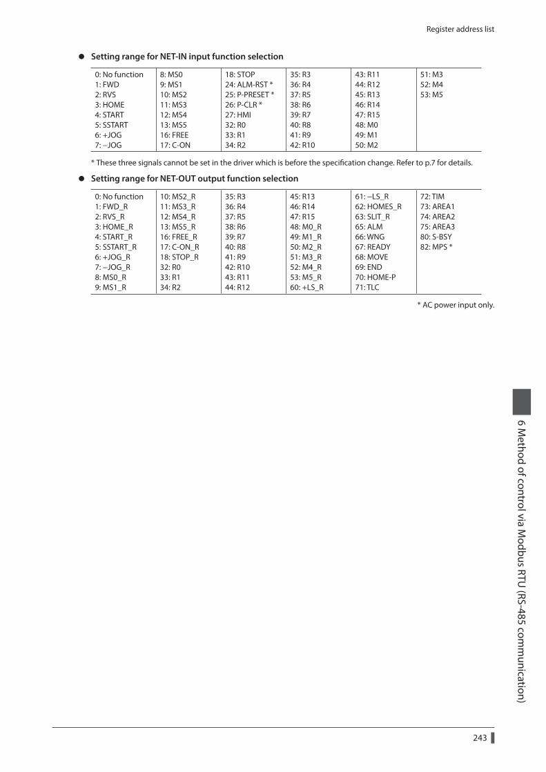
Register address list6 M
ethod of control via Modbus RTU
(RS-485 comm
unication)
243
z Setting range for NET-IN input function selection
0: No function 1: FWD 2: RVS 3: HOME 4: START 5: SSTART 6: +JOG 7: −JOG
8: MS0 9: MS1 10: MS2 11: MS3 12: MS4 13: MS5 16: FREE 17: C-ON
18: STOP 24: ALM-RST * 25: P-PRESET * 26: P-CLR * 27: HMI 32: R0 33: R1 34: R2
35: R3 36: R4 37: R5 38: R6 39: R7 40: R8 41: R9 42: R10
43: R11 44: R12 45: R13 46: R14 47: R15 48: M0 49: M1 50: M2
51: M3 52: M4 53: M5
* These three signals cannot be set in the driver which is before the specification change. Refer to p.7 for details.
z Setting range for NET-OUT output function selection
0: No function 1: FWD_R 2: RVS_R 3: HOME_R 4: START_R 5: SSTART_R 6: +JOG_R 7: −JOG_R 8: MS0_R 9: MS1_R
10: MS2_R 11: MS3_R 12: MS4_R 13: MS5_R 16: FREE_R 17: C-ON_R 18: STOP_R 32: R0 33: R1 34: R2
35: R3 36: R4 37: R5 38: R6 39: R7 40: R8 41: R9 42: R10 43: R11 44: R12
45: R13 46: R14 47: R15 48: M0_R 49: M1_R 50: M2_R 51: M3_R 52: M4_R 53: M5_R 60: +LS_R
61: −LS_R 62: HOMES_R 63: SLIT_R 65: ALM 66: WNG 67: READY 68: MOVE 69: END 70: HOME-P 71: TLC
72: TIM 73: AREA1 74: AREA2 75: AREA3 80: S-BSY 82: MPS *
* AC power input only.

Group send
6 Method of control via M
odbus RTU (RS-485 com
munication)
244
9 Group send
Multiple slaves are made into a group and a query is sent to all slaves in the group at once.
Group compositionA group consists of one parent slave and child slaves and only the parent slave returns a response.
z Group addressTo perform a group send, set a group address to the child slaves to be included in the group.The child slaves to which the group address has been set can receive a query sent to the parent slave.
Query (send tothe parent slave)
Query (send tothe parent slave)
Response
Master
Master
Parent slave
Child slave Execute the process but doesnot sent a response.
z Parent slaveNo special setting is required on the parent slave to perform a group send. The address of the parent slave becomes the group address. When a query is sent to the parent slave from the master, the parent slave executes the requested process and then returns a response (same as with the unicast mode).
z Child slaveUse a "Group" command to set a group address to each child slave. Change the group in the unicast mode.When setting a group, read/write to the upper and lower at the same time.
Register addressName Description
READ/WRITE
Setting rangeDec Hex
48 0030h Group (upper)Sets the group address. R/W
−1 : No group specification (Group send is not performed) 1 to 31 : Group address (Address number of parent slave) 49 0031h Group (lower)
Since the group setting is not saved in the non-volatile memory even when the "Batch non-volatile memory write" executes, the group setting will be cleared when turning the driver power supply OFF.
Function code to execute in a group send
Function code Function
10h Writing to multiple holding registers
Master controller
Address 1“Group” command: -1
(individual)
Address 2“Group” command: 1
Address 3“Group” command: 1
Parentslave
Childslave
Childslave
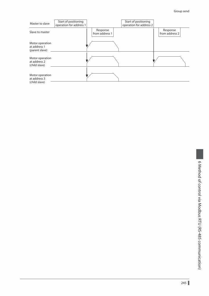
Group send6 M
ethod of control via Modbus RTU
(RS-485 comm
unication)
245
Start of positioningoperation for address 1
Responsefrom address 1
Motor operationat address 1(parent slave)
Motor operationat address 2(child slave)
Motor operationat address 3(child slave)
Start of positioningoperation for address 2
Responsefrom address 2
Master to slave
Slave to master
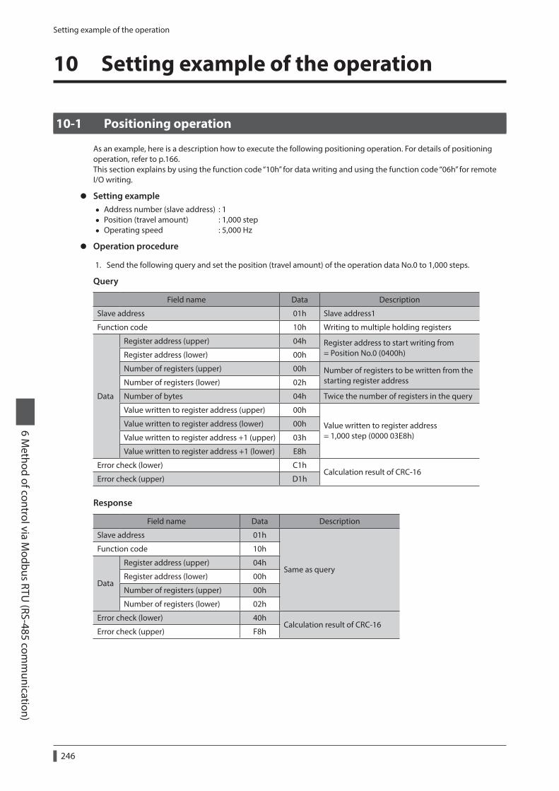
Setting example of the operation
6 Method of control via M
odbus RTU (RS-485 com
munication)
246
10 Setting example of the operation
10-1 Positioning operation
As an example, here is a description how to execute the following positioning operation. For details of positioning operation, refer to p.166.This section explains by using the function code “10h” for data writing and using the function code “06h” for remote I/O writing.
z Setting example • Address number (slave address) : 1 • Position (travel amount) : 1,000 step • Operating speed : 5,000 Hz
z Operation procedure
1. Send the following query and set the position (travel amount) of the operation data No.0 to 1,000 steps.
Query
Field name Data Description
Slave address 01h Slave address1
Function code 10h Writing to multiple holding registers
Data
Register address (upper) 04h Register address to start writing from = Position No.0 (0400h)Register address (lower) 00h
Number of registers (upper) 00h Number of registers to be written from the starting register addressNumber of registers (lower) 02h
Number of bytes 04h Twice the number of registers in the query
Value written to register address (upper) 00h
Value written to register address = 1,000 step (0000 03E8h)
Value written to register address (lower) 00h
Value written to register address +1 (upper) 03h
Value written to register address +1 (lower) E8h
Error check (lower) C1hCalculation result of CRC-16
Error check (upper) D1h
Response
Field name Data Description
Slave address 01h
Same as query
Function code 10h
Data
Register address (upper) 04h
Register address (lower) 00h
Number of registers (upper) 00h
Number of registers (lower) 02h
Error check (lower) 40hCalculation result of CRC-16
Error check (upper) F8h

Setting example of the operation6 M
ethod of control via Modbus RTU
(RS-485 comm
unication)
247
2. Send the following query and set the operating speed of the operation data No.0 to 5,000 Hz.
Query
Field name Data Description
Slave address 01h Slave address1
Function code 10h Writing to multiple holding registers
Data
Register address (upper) 04h Register address to start writing from = Operating speed No.0 (0480h)Register address (lower) 80h
Number of registers (upper) 00h Number of registers to be written from the starting register address Number of registers (lower) 02h
Number of bytes 04h Twice the number of registers in the query
Value written to register address (upper) 00h
Value written to register address = 5,000 Hz (0000 1388h)
Value written to register address (lower) 00h
Value written to register address +1 (upper) 13h
Value written to register address +1 (lower) 88h
Error check (lower) C4hCalculation result of CRC-16
Error check (upper) 59h
Response
Field name Data Description
Slave address 01h
Same as query
Function code 10h
Data
Register address (upper) 04h
Register address (lower) 80h
Number of registers (upper) 00h
Number of registers (lower) 02h
Error check (lower) 41hCalculation result of CRC-16
Error check (upper) 10h
3. Send the following query and turn START ON.Positioning operation is started.
Query
Field name Data Description
Slave address 01h Slave address1
Function code 06h Writing to a holding register
Data
Register address (upper) 00h Register address to which writing is executed = Driver input command (007Dh)Register address (lower) 7Dh
Value written (upper) 00h Value written to register address = START ON (0008h)Value written (lower) 08h
Error check (lower) 18hCalculation result of CRC-16
Error check (upper) 14h

Setting example of the operation
6 Method of control via M
odbus RTU (RS-485 com
munication)
248
Response
Field name Data Description
Slave address 01h
Same as query
Function code 06h
Data
Register address (upper) 00h
Register address (lower) 7Dh
Value written (upper) 00h
Value written (lower) 08h
Error check (lower) 18hCalculation result of CRC-16
Error check (upper) 14h
4. When positioning operation is started, send the following query and turn START OFF again.
Query
Field name Data Description
Slave address 01h Slave address1
Function code 06h Writing to a holding register
Data
Register address (upper) 00h Register address to which writing is executed = Driver input command (007Dh)Register address (lower) 7Dh
Value written (upper) 00h Value written to register address = START OFF (0000h)Value written (lower) 00h
Error check (lower) 19hCalculation result of CRC-16
Error check (upper) D2h
Response
Field name Data Description
Slave address 01h
Same as query
Function code 06h
Data
Register address (upper) 00h
Register address (lower) 7Dh
Value written (upper) 00h
Value written (lower) 00h
Error check (lower) 19hCalculation result of CRC-16
Error check (upper) D2h

Setting example of the operation6 M
ethod of control via Modbus RTU
(RS-485 comm
unication)
249
10-2 Continuous operation
As an example, here is a description how to execute the following continuous operation. For details of continuous operation, refer to p.188.This section explains by using the function code “10h” for data writing and using the function code “06h” for remote I/O writing.
z Setting example • Address number (slave address) : 1 • Rotation direction : Forward direction (FWD) • Operating speed : 5,000 Hz
z Operation procedure
1. Send the following query and set the operating speed of the operation data No.0 to 5,000 Hz.
Query
Field name Data Description
Slave address 01h Slave address1
Function code 10h Writing to multiple holding registers
Data
Register address (upper) 04h Register address to start writing from = Operating speed No.0 (0480h)Register address (lower) 80h
Number of registers (upper) 00h Number of registers to be written from the starting register addressNumber of registers (lower) 02h
Number of bytes 04h Twice the number of registers in the query
Value written to register address (upper) 00h
Value written to register address = 5,000 Hz (0000 1388h)
Value written to register address (lower) 00h
Value written to register address +1 (upper) 13h
Value written to register address +1 (lower) 88h
Error check (lower) C4hCalculation result of CRC-16
Error check (upper) 59h
Response
Field name Data Description
Slave address 01h
Same as query
Function code 10h
Data
Register address (upper) 04h
Register address (lower) 80h
Number of registers (upper) 00h
Number of registers (lower) 02h
Error check (lower) 41hCalculation result of CRC-16
Error check (upper) 10h

Setting example of the operation
6 Method of control via M
odbus RTU (RS-485 com
munication)
250
2. Send the following query and turn FWD ON.Continuous operation is started.
Query
Field name Data Description
Slave address 01h Slave address1
Function code 06h Writing to a holding register
Data
Register address (upper) 00h Register address to which writing is executed = Driver input command (007Dh)Register address (lower) 7Dh
Value written (upper) 40h Value written to register address = FWD ON (4000h)Value written (lower) 00h
Error check (lower) 28hCalculation result of CRC-16
Error check (upper) 12h
Response
Field name Data Description
Slave address 01h
Same as query
Function code 06h
Data
Register address (upper) 00h
Register address (lower) 7Dh
Value written (upper) 40h
Value written (lower) 00h
Error check (lower) 28hCalculation result of CRC-16
Error check (upper) 12h
3. To stop continuous operation, send the following query and turn FWD OFF again.The motor decelerates to a stop.
Query
Field name Data Description
Slave address 01h Slave address1
Function code 06h Writing to a holding register
Data
Register address (upper) 00h Register address to which writing is executed = Driver input command (007Dh)Register address (lower) 7Dh
Value written (upper) 00h Value written to register address = FWD OFF (0000h)Value written (lower) 00h
Error check (lower) 19hCalculation result of CRC-16
Error check (upper) D2h
Response
Field name Data Description
Slave address 01h
Same as query
Function code 06h
Data
Register address (upper) 00h
Register address (lower) 7Dh
Value written (upper) 00h
Value written (lower) 00h
Error check (lower) 19hCalculation result of CRC-16
Error check (upper) D2h

Setting example of the operation6 M
ethod of control via Modbus RTU
(RS-485 comm
unication)
251
10-3 Return-to-home operation
As an example, here is a description how to execute the following return-to-home operation. For details of return-to-home operation, refer to p.180.
z Setting example • Address number (slave address) : 1 • Operation condition : Initial value
z Operation procedure
1. Send the following query and turn HOME ON.Return-to-home operation is started.
Query
Field name Data Description
Slave address 01h Slave address1
Function code 06h Writing to a holding register
Data
Register address (upper) 00h Register address to which writing is executed = Driver input command (007Dh)Register address (lower) 7Dh
Value written (upper) 00h Value written to register address = HOME ON (0010h)Value written (lower) 10h
Error check (lower) 18hCalculation result of CRC-16
Error check (upper) 1Eh
Response
Field name Data Description
Slave address 01h
Same as query
Function code 06h
Data
Register address (upper) 00h
Register address (lower) 7Dh
Value written (upper) 00h
Value written (lower) 10h
Error check (lower) 18hCalculation result of CRC-16
Error check (upper) 1Eh
2. When Return-to-home operation is started, send the following query and turn HOME OFF again.
Query
Field name Data Description
Slave address 01h Slave address1
Function code 06h Writing to a holding register
Data
Register address (upper) 00h Register address to which writing is executed = Driver input command (007Dh)Register address (lower) 7Dh
Value written (upper) 00h Value written to register address = HOME OFF (0000h)Value written (lower) 00h
Error check (lower) 19hCalculation result of CRC-16
Error check (upper) D2h

Setting example of the operation
6 Method of control via M
odbus RTU (RS-485 com
munication)
252
Response
Field name Data Description
Slave address 01h
Same as query
Function code 06h
Data
Register address (upper) 00h
Register address (lower) 7Dh
Value written (upper) 00h
Value written (lower) 00h
Error check (lower) 19hCalculation result of CRC-16
Error check (upper) D2h

Detection of communication errors6 M
ethod of control via Modbus RTU
(RS-485 comm
unication)
253
11 Detection of communication errors
This function detects abnormalities that may occur during RS-485 communication. The abnormalities that can be detected include communication errors, alarms and warnings.
11-1 Communication errors
A communication error record will be saved in the RAM. You can check the communication errors using the MEXE02 or "Communication error record" command via RS-485 communication.
You can also clear the communication error records by turning off the driver power supply.
Type of communication error Error code Cause
RS-485 communication error 84h A transmission error was detected. See “No response” on p.219.
Command not yet defined 88hAn exception response (exception code 01h, 02h) was detected. See p.220.
Execution disable due to user I/F communication in progress
89h
An exception response (exception code 04h) was detected. See p.220.Not possible to execute because of non-volatile memory processing
8Ah
Outside setting range 8ChAn exception response (exception code 03h, 04h) was detected. See p.220.
Command execute disable 8Dh An exception response (exception code 04h) was detected. See p.220.
11-2 Alarms and warnings
When an alarm generates, the ALM output will turn OFF and the motor will stop. At the same time, the ALM LED (or ALARM LED) will start blinking.When a warning generates, the WNG output will turn ON. The motor will continue to operate. Once the cause of the warning is removed, the WNG output will turn OFF automatically.
You can also clear the warning records by turning off the driver power supply.
Communication switch setting errorWhen setting the transmission rate setting switch (SW2) to positions 8 to F, the transmission rate setting switch error will occur.
RS-485 communication error (84h)The table shows the relationship between alarms and warnings when an RS-485 communication error occurs.
Description of error
Description
WarningA warning generates when one RS-485 communication error (84h) has been detected. If normal reception occurs while the warning is present, the warning will be reset automatically.
AlarmAn alarm generates when a RS-485 communication error (84h) has been detected consecutively by the number of times set in the “Communication error alarm” parameter.
RS-485 communication timeout (85h)If communication is not established with the master after an elapse of the time set by the “Communication timeout” parameter, a RS-485 communication timeout alarm will generate.

Timing charts
6 Method of control via M
odbus RTU (RS-485 com
munication)
254
12 Timing charts
Communication start
Query
ResponseMaster
Slave
Power supply input
Communication
ONOFF
1 s or more *
* Tb2 (transmission waiting time) + C3.5 (silent interval)
Operation start
Query *1Response
Master
Slave
MOVE output
Communication
ONOFF
*2
*3
*1 A message including a query to start operation via RS-485 communication.*2 Tb2 (transmission waiting time) + C3.5 (silent interval)*3 C3.5 (silent interval) + 4 ms or less
Operation stop, speed change
Query *1Response
Master
Slave
Motor speed command
Communication
*4
*2
*3
*1 A message including a query to stop operation and another to change the speed via RS-485 communication.*2 Tb2 (transmission waiting time) + C3.5 (silent interval)*3 The specific time varies depending on the command speed.*4 The deceleration method to be applied at the time of stopping varies according to the “STOP input action”
parameter.
General signals
Query *1Response
Master
SlaveCommunication
*2
*3
General signalsON
OFF
*1 A message including a query for remote output via RS-485 communication.*2 Tb2 (transmission waiting time) + C3.5 (silent interval)*3 C3.5 (silent interval) + 4 ms or less

Timing charts6 M
ethod of control via Modbus RTU
(RS-485 comm
unication)
255
Configuration
Response
Master
Slave
Internal processing Internal processing was in progress
Communication
*2
*3
Query *1 Query
*4
*1 A message including a query for configuration via RS-485 communication.*2 Tb2 (transmission waiting time) + C3.5 (silent interval)*3 Command processing time + 1 s or less*4 Execute a query after the driver internal processing is completed.

6 Method of control via M
odbus RTU (RS-485 com
munication)
256

7 Method of control via industrial network
This part explains how to control via industrial network using the network converter (accessory).
Table of contents
1 Setting the switches ............................2581-1 Setting the AC power input ......................2581-2 Setting the DC power input ......................260
2 Method of control via CC-Link communication ....................................262
2-1 Guidance ..........................................................2622-2 Operation example of command
selection method ..........................................2672-3 Operation example of command
fixation method .............................................275
3 Method of control via EtherCAT communication ....................................281
3-1 Guidance ..........................................................2813-2 Basic operating procedures ......................287
4 Details of remote I/O ...........................2904-1 Input signals to the driver .........................2904-2 Output signals from the driver ................291
5 Command code list .............................2935-1 Group function ..............................................2935-2 Maintenance command .............................2945-3 Monitor command .......................................2955-4 Operation data ..............................................2975-5 User parameters ............................................298

Setting the switches
7 Method of control via industrial netw
ork
258
1 Setting the switches
Switches differ in the AC input driver and the DC input driver. Set properly.
1-1 Setting the AC power input
The figures show the status of factory setting.
Address numbersetting switch (ID)
Termination resistor setting switch (TERM.)
Driver front side Driver bottom side
Transmission ratesetting switch (SW2)
Function setting switch (SW4) No.1: Sets the address number. No.2: Sets the protocol.
No.2: OFFNo.1: OFF
No.1: OFFNo.2: OFF
Be sure to turn off the control power supply of the driver before setting the switches. If the switches are set while the power is still on, the new switch settings will not become effective until the control power supply of the driver is cycled.
ProtocolSet the SW4-No.2 of the function setting switch to OFF. The network converter is selected.
Factory setting OFF
SW4-No.2 Protocol
ON Modbus RTU protocol
OFF Connect to the network converter
Address number (slave address)Using the address number setting switch (ID) and SW4-No.1 of the function setting switch, set the address number (slave address). Make sure each address number (slave address) you set for each driver is unique.Up to 16 units can be connected.
Factory setting ID: 0, SW4-No.1: OFF (slave address 0)
Address number 0 1 2 3 4 5 6 7 8 9 10 11 12 13 14 15
ID 0 1 2 3 4 5 6 7 8 9 A B C D E F
SW4-No.1 OFF
Transmission rateUsing the transmission rate setting switch (SW2), set the transmission rate to 625,000 bps.
Factory setting 7 (625,000 bps)

Setting the switches7 M
ethod of control via industrial network
259
Termination resistorUse a termination resistor for the driver located farthest away (positioned at the end) from the network converter. Turn the termination resistor setting switch (TERM.-Nos.1 and 2) ON to set the termination resistor for RS-485 communication (120 Ω).
Factory setting Nos.1 and 2: Both OFF (termination resistor disabled)
TERM.-Nos.1 and 2 Termination resistor (120 Ω)
Both are OFF Disabled
Both are ON Enabled
If only one of No.1 or No.2 is turned ON, a communication error may occur.
For example, in the case of the following system, the termination resistor should be set to two drivers.
DriverNetwork converter
Driver Driver
RS-485 communication
Master controller
DriverNetwork converter
Driver
RS-485 communication
CC-Link communication
Terminationresistor: ON
Terminationresistor: ON

Setting the switches
7 Method of control via industrial netw
ork
260
1-2 Setting the DC power input
The figures show the status of factory setting.
Transmission ratesetting switch (SW2)
Address numbersetting switch (SW1)
Function setting switch (SW3) No.1: Sets the address number. No.2: Sets the protocol. No.3: Not used. No.4: Sets the termination resistor.
No.1: OFFNo.2: OFFNo.3: OFFNo.4: OFF
Driver front side Driver top side
Be sure to turn off the driver power supply before setting the switches. If the switches are set while the power is still on, the new switch settings will not become effective until the driver power supply is cycled.
ProtocolSet the SW3-No.2 of the function setting switch to OFF. The network converter is selected.
Factory setting OFF
SW3-No.2 Protocol
ON Modbus RTU protocol
OFF Connect to the network converter
Address number (slave address)Using the address number setting switch (SW1) and SW3-No.1 of the function setting switch, set the address number (slave address). Make sure each address number (slave address) you set for each driver is unique.Up to 16 units can be connected.
Factory setting SW1: 0, SW3-No.1: OFF (slave address 0)
Address number 0 1 2 3 4 5 6 7 8 9 10 11 12 13 14 15
SW1 0 1 2 3 4 5 6 7 8 9 A B C D E F
SW3-No.1 OFF
Transmission rateUsing the transmission rate setting switch (SW2), set the transmission rate to 625,000 bps.
Factory setting 7 (625,000 bps)

Setting the switches7 M
ethod of control via industrial network
261
Termination resistorUse a termination resistor for the driver located farthest away (positioned at the end) from the network converter. Turn the termination resistor setting switches (SW3-No.4) ON to set the termination resistor for RS-485 communication (120 Ω).
Factory setting OFF (termination resistor disabled)
SW3-No.4 Termination resistor (120 Ω)
OFF Disabled
ON Enabled
For example, in the case of the following system, the termination resistor should be set to two drivers.
Driver
Networkconverter
Driver Driver
RS-485 communicationMaster controller
Driver
Networkconverter
Driver
RS-485 communication
CC-Link communication
Terminationresistor: ON
Terminationresistor: ON

Method of control via CC-Link communication
7 Method of control via industrial netw
ork
262
2 Method of control via CC-Link communication
2-1 Guidance
If you are new to the AR Series FLEX built-in controller type, read this section to understand the operating methods along with the operation flow.
STEP1 Installation and connection _ p.264
STEP2 Setting of NETC02-CC _ p.265
STEP3 Setting of driver _ p.266
STEP4 Turn on the power and check the LED _ p.267
Setting of data with selecting the command execution method Command selection method _ p.267
This is a method to execute with setting the command code, address number, and data. Read and write of data, monitor, and each command of maintenance are executed by the request signal "D-REQ."
Command fixation method _ p.275
This is a method to execute with reading and writing data.The command code and address number are fixed. Write of data is started by the request signal "WR-REQ," and read of data and monitor are started by the request signal "RD-REQ."

Method of control via CC-Link communication 7 M
ethod of control via industrial network
263
Setting condition
z Setting of driver
Address number 0 AC power input
Address number 1 DC power input
Protocol Network converter
RS-485 communication transmission rate
625,000 bps
z Setting of NETC02-CC
Number of connected driver 2 units
CC-Link baud rate 10 Mbps
STATION No. No.1
Register arrangement mode 4 word arrangement
z Setting of the master device
Setting of network parameter
Remote input (RX) RX1000
Remote output (RY) RY1000
Remote register (RWr) W0
Remote register (RWw) W100
Extended cyclic setting ×2
Remote device station 4 station occupied
Setting of CC-Link master
CC-Link baud rate 10 Mbps
STATION No. No.0
Before operating the motor, check the condition of the surrounding area to ensure safety.
The NETC02-CC incorporates a termination resistor for RS-485 communication. This product can be used without setting the termination resistor.

Method of control via CC-Link communication
7 Method of control via industrial netw
ork
264
STEP 1 Check the installation and connection
Connect to CN6 or CN7
CN1 connector [Address number 0]AC power supply driver
RS-485 communication cable
CC-Link communication cable
Connect to USB communication connector
USB cable
Connect to CN2
Mastercontroller
[Address number 1]DC power supply driver
NETC02-CC
Connect to CN6
24 VDCpower supply
Terminationresistor *3
Connect to CN6 or CN7
Grounding
Connect to CN1DC powersupply
Connect to CN2
Motor cable Cable for motor *1 *2
Connect to + and -
Connect to CN2
Main power supply
Cable for motor *1
24 VDCpower supply
Required
Required
GroundingGrounding
Grounding
Grounding
PC in which the MEXE02 has been installed
*1 Accessory. *2 Use the cable for motor when the length of the motor cable is not enough.*3 The termination resistor does not come with the product (110 Ω, 1/2 W).

Method of control via CC-Link communication 7 M
ethod of control via industrial network
265
STEP 2 Set the switches of the NETC02-CC
Set the switches provided on the upper side of the NETC02-CC as follows. The status becomes as shown in the following figures after setting.
Setting item Switch Factory setting
RS-485 communication connection unit: 2 Set N-AXIS to "2" 1
CC-Link baud rate: 10 Mbps Set B-RATE to "4" 0
CC-Link station No.: 1Set the ×1 to "1" and the ×10 to "0" of the STATION No.
1 (×1: 1, ×10: 0)
Operation mode: OFF Set No.1 to No.4 to "OFF" All OFF
RS-485 communication connected units setting switch (N-AXIS)
Operation mode setting switch(SW2)
CC-Link baud rate setting switch (B-RATE)
CC-Link station number setting switches(STATION No.)
ON

Method of control via CC-Link communication
7 Method of control via industrial netw
ork
266
STEP 3 Set the switches of the driver
Set the following with the switches of the driver. The status becomes as shown in the following figures after setting.
Setting item AC power input DC power input
Protocol: Network converter Set No.2 of SW4 to "OFF" Set No.2 of SW3 to "OFF"
Address number: AC power input driver is "0" DC power input driver is "1"
Set No.1 of SW4 to "OFF" Set ID to "0"
Set No.1 of SW3 to "OFF" Set SW1 to "1"
Termination resistor: AC power input driver is "OFF" DC power input driver is "ON"
Set No.1 and No.2 of TERM. to "OFF" Set No.4 of SW3 to "ON"
Transmission rate: 625,000 bps Set SW2 to "7" Set SW2 to "7"
AC power input
Address numbersetting switch (ID)
Termination resistor setting switch (TERM.)
Driver front side Driver bottom side
Transmission ratesetting switch (SW2)
Function setting switch (SW4) No.1: Sets the address number. No.2: Sets the protocol.
No.2: OFFNo.1: OFF
No.1: OFFNo.2: OFF
DC power input
Transmission ratesetting switch (SW2)
Address numbersetting switch (SW1)
Function setting switch (SW3) No.1: Sets the address number. No.2: Sets the protocol. No.3: Not used. No.4: Sets the termination resistor.
No.1: OFFNo.2: OFFNo.3: OFFNo.4: ON
Driver front side Driver top side

Method of control via CC-Link communication 7 M
ethod of control via industrial network
267
STEP 4 Turn on the power and check the LED
Check that the LED of the driver and networ converter are as shown in the figure.
Network converter AC power input driver DC power input driver
Green litGreen lit
Green lit
Green lit Green lit
2-2 Operation example of command selection method
This section explains how to perform the following operations using the command selection method.
STEP1 Check an operation Execute continuous operation in the reverse direction, and check if the operation is performed.
STEP2 Perform positioning operation Set the position data, and check if the operation is performed.
STEP3 Monitor the actual position Check if positioning operation in the STEP 2 was properly performed.
STEP4 Write to non-volatile memory Write the position data to the non-volatile memory.
How to use the request signalIn the operation example, the request signals are used quite differently based on the setting of remote register.
z Operation data, maintenance command z Monitor command
Request signalRemote register
Request signalRemote register
Write Read Write Read
D-REQ0
RWw100 RWr0
D-REQ2
RWw108 RWr8
RWw101 RWr1 RWw109 RWr9
RWw102 RWr2 RWw10A RWrA
RWw103 RWr3 RWw10B RWrB
D-REQ1
RWw104 RWr4
D-REQ3
RWw10C RWrC
RWw105 RWr5 RWw10D RWrD
RWw106 RWr6 RWw10E RWrE
RWw107 RWr7 RWw10F RWrF

Method of control via CC-Link communication
7 Method of control via industrial netw
ork
268
STEP 1 Execute continuous operation in the reverse direction by remote I/O, and check if the operation is performed.
1. Start continuous operation in the reverse direction.Turn the RVS ON.
Master to NETC02-CC
Address number Remote I/O Address Input value Description
0RVS
RY100F 1Execution of continuous operation
1 RY101F 1
2. Stop continuous operation.Turn the RVS OFF.
Master to NETC02-CC
Address number Remote I/O Address Input value Description
0RVS
RY100F 0Stop of continuous operation
1 RY101F 0
If not operated, check the setting of the switches, and assignments of remote I/O and remote register.
STEP 2 Perform positioning operation
1. In order to make easier to check that the operation was properly performed when positioning operation was performed, set the position information to "0."
1) Set the maintenance command "P-PRESET execution (30C5h)" to remote register.
Master to NETC02-CC
Address number Address Input value Description
0
RWw100 30C5h Command code (P-PRESET execution)
RWw101 0h Address number
RWw102 1 Data (lower)
RWw103 0 Data (upper)
1
RWw104 30C5h Command code (P-PRESET execution)
RWw105 1h Address number
RWw106 1 Data (lower)
RWw107 0 Data (upper)
Unless "1" is set to the data area, the command is not executed.
2) Turn the D-REQ ON to write data to the driver.
Master to NETC02-CC
Address number Remote I/O Address Input value Description
0 D-REQ0 RY1080 1Write execution
1 D-REQ1 RY1082 1

Method of control via CC-Link communication 7 M
ethod of control via industrial network
269
3) The response of the D-END is automatically changed to "1" when it is properly processed.
NETC02-CC to master
Address number Remote I/O Address Response Description
0 D-END0 RX1080 1Write completed
1 D-END1 RX1082 1
4) The value written to the driver is displayed when the response of the D-END is changed to "1." Check the value is matched with the one having set in the above 1).
NETC02-CC to master
Address number Address Response Description
0
RWr0 30C5h Command code response (P-PRESET execution)
RWr1 0h Address number response
RWr2 1 Data (lower)
RWr3 0 Data (upper)
1
RWr4 30C5h Command code response (P-PRESET execution)
RWr5 1h Address number response
RWr6 1 Data (lower)
RWr7 0 Data (upper)
5) Check it has been written properly, and turn the D-REQ OFF.
Master to NETC02-CC
Address number Remote I/O Address Input value Description
0 D-REQ0 RY1080 0Write execution
1 D-REQ1 RY1082 0
2. Check the position information is changed to "0" by the "P-PRESET execution" of the maintenance command.
1) Set the "Actual position (2066h)" of the monitor command to remote register.
Master to NETC02-CC
Address number Address Input value Description
0
RWw108 2066h Command code (actual position)
RWw109 0h Address number
RWw10A 0 Data (lower)
RWw10B 0 Data (upper)
1
RWw10C 2066h Command code (actual position)
RWw10D 1h Address number
RWw10E 0 Data (lower)
RWw10F 0 Data (upper)
2) Turn the D-REQ ON to write data to the driver.
Master to NETC02-CC
Address number Remote I/O Address Input value Description
0 D-REQ2 RY1084 1Start of monitor
1 D-REQ3 RY1086 1

Method of control via CC-Link communication
7 Method of control via industrial netw
ork
270
3) The response of the D-END is automatically changed to "1" when it is properly processed.
NETC02-CC to master
Address number Remote I/O Address Response Description
0 D-END2 RX1084 1During monitor
1 D-END3 RX1086 1
4) The value written to the driver is displayed when the response of the D-END is changed to "1." Check the data area is changed to "0."
NETC02-CC to master
Address number Address Response Description
0
RWr8 2066h Command code response (actual position)
RWr9 0h Address number response
RWrA 0 Data (lower)
RWrB 0 Data (upper)
1
RWrC 2066h Command code response (actual position)
RWrD 1h Address number response
RWrE 0 Data (lower)
RWrF 0 Data (upper)
5) Check it has been written properly, and turn the D-REQ OFF.
Master to NETC02-CC
Address number Remote I/O Address Input value Description
0 D-REQ2 RY1084 0End of monitor
1 D-REQ3 RY1086 0
3. Set the operation data of positioning operation.Set the position No.0 and position data "5,000 (1388h)" to remote register.
Master to NETC02-CC
Address number Address Input value Description
0
RWw100 1200h Command code (position No.0)
RWw101 0h Address number
RWw102 5,000 (1388h)
Data (lower)
RWw103 Data (upper)
1
RWw104 1200h Command code (position No.0)
RWw105 1h Address number
RWw106 5,000 (1388h)
Data (lower)
RWw107 Data (upper)
4. Write the set data in the above 3 to the driver to check the response.
1) Turn the D-REQ ON.
Master to NETC02-CC
Address number Remote I/O Address Input value Description
0 D-REQ0 RY1080 1Write execution
1 D-REQ1 RY1082 1

Method of control via CC-Link communication 7 M
ethod of control via industrial network
271
2) The response of the D-END is automatically changed to "1" when it is properly processed.
NETC02-CC to master
Address number Remote I/O Address Response Description
0 D-END0 RX1080 1Write completed
1 D-END1 RX1082 1
3) The value written to the driver is displayed when the response of the D-END is changed to "1." Check the value is matched with the one having set in the above 3.
NETC02-CC to master
Address number Address Response Description
0
RWr0 1200h Command code response (position No.0)
RWr1 0h Address number response
RWr2 5,000 (1388h)
Data (lower)
RWr3 Data (upper)
1
RWr4 1200h Command code response (position No.0)
RWr5 1h Address number response
RWr6 5,000 (1388h)
Data (lower)
RWr7 Data (upper)
5. Check it has been written properly, and turn the D-REQ OFF.
Master to NETC02-CC
Address number Remote I/O Address Input value Description
0 D-REQ0 RY1080 0Write completed
1 D-REQ1 RY1082 0
6. Start positioning operation.Turn the START ON.
Master to NETC02-CC
Address number Remote I/O Address Input value Description
0START
RY1003 1Start of positioning operation
1 RY1013 1
7. When positioning operation is started, turn the START OFF.Even if the START is turned OFF, the operation continues until the command position.
NETC02-CC to master
Address number Remote I/O Address Input value Description
0START
RY1003 0Turn the START OFF
1 RY1013 0

Method of control via CC-Link communication
7 Method of control via industrial netw
ork
272
STEP 3 Monitor the actual position
1. Set the "Actual position (2066h)" of the monitor command to remote register.
Master to NETC02-CC
Address number Address Input value Description
0
RWw108 2066h Command code (actual position)
RWw109 0h Address number
RWw10A 0 Data (lower)
RWw10B 0 Data (upper)
1
RWw10C 2066h Command code (actual position)
RWw10D 1h Address number
RWw10E 0 Data (lower)
RWw10F 0 Data (upper)
2. Write the set data in the above 1 to the driver to check the response.
1) Turn the D-REQ ON.
Master to NETC02-CC
Address number Remote I/O Address Input value Description
0 D-REQ2 RY1084 1Start of monitor
1 D-REQ3 RY1086 1
2) The response of the D-END is automatically changed to "1" when it is properly processed.
NETC02-CC to master
Address number Remote I/O Address Response Description
0 D-END2 RX1084 1During monitor
1 D-END3 RX1086 1
3) The response of the D-END is changed to "1," the monitor of the actual position is started. The monitor is continued while the D-REQ is ON.
NETC02-CC to master
Address number Address Response Description
0
RWr8 2066h Command code response (actual position)
RWr9 0h Address number response
RWrA 5,000 (1388h)
Data (lower)
RWrB Data (upper)
1
RWrC 2066h Command code response (actual position)
RWrD 1h Address number response
RWrE 5,000 (1388h)
Data (lower)
RWrF Data (upper)
3. End the monitor.Turn the D-REQ OFF.
Master to NETC02-CC
Address number Remote I/O Address Input value Description
0 D-REQ2 RY1084 0End of monitor
1 D-REQ3 RY1086 0

Method of control via CC-Link communication 7 M
ethod of control via industrial network
273
STEP 4 Write the position information to the non-volatile memory.
The non-volatile memory can be rewritten approximately 100,000 times.
1. Set the maintenance command "Batch non-volatile memory write (30C9h)" to remote register.
Master to NETC02-CC
Address number Address Input value Description
0
RWw100 30C9hCommand code
(batch non-volatile memory write)
RWw101 0h Address number
RWw102 1 Data (lower)
RWw103 0 Data (upper)
1
RWw104 30C9hCommand code
(batch non-volatile memory write)
RWw105 1h Address number
RWw106 1 Data (lower)
RWw107 0 Data (upper)
2. Write the set data in the above 1 to the driver to check the response.
1) Turn the D-REQ ON.
Master to NETC02-CC
Address number Remote I/O Address Input value Description
0 D-REQ0 RY1080 1Write execution
1 D-REQ1 RY1082 1
2) The response of the D-END is automatically changed to "1" when it is properly processed.
NETC02-CC to master
Address number Remote I/O Address Response Description
0 D-END0 RX1080 1Write completed
1 D-END1 RX1082 1
3) The value written to the driver is displayed when the response of the D-END is changed to "1." Check the value is matched with the one having set in the above 1).
NETC02-CC to master
Address number Address Response Description
0
RWr0 30C9hCommand code response
(batch non-volatile memory write)
RWr1 0h Address number response
RWr2 1 Data (lower)
RWr3 0 Data (upper)
1
RWr4 30C9hCommand code response
(batch non-volatile memory write)
RWr5 1h Address number response
RWr6 1 Data (lower)
RWr7 0 Data (upper)

Method of control via CC-Link communication
7 Method of control via industrial netw
ork
274
3. Check it has been written properly, and turn the D-REQ OFF.
Master to NETC02-CC
Address number Remote I/O Address Input value Description
0 D-REQ0 RY1080 0Write completed
1 D-REQ1 RY1082 0
Since the data set via CC-Link communication is saved in the RAM, it is erased when the power is turned off. If the "batch non-volatile memory write" is performed, since the data is saved in the non-volatile memory, it is stored even when the power is turned off.

Method of control via CC-Link communication 7 M
ethod of control via industrial network
275
2-3 Operation example of command fixation method
This section explains how to perform the following operations using the command fixation method.
STEP1 Check an operation Execute continuous operation in the reverse direction, and check if the operation is performed.
STEP2 P-PRESET execution Set the present position to "0."
STEP3 Monitor the value of the driver Read the monitor of the actual position and the value of the position No.0.
STEP4 Perform positioning operation Set the data of the position No.0 to execute positioning operation.
STEP5 Change of the position data Change the data of the position No.0.
Items of register arrangement (four words arrangement)
z Arrangement of write
Address number Remote register Description Request signal
0
RWw100 Not used
WR-REQ0
RWw101 Not used
RWw102 Position No.0 (lower)
RWw103 Position No.0 (upper)
1
RWw104 Not used
RWw105 Not used
RWw106 Position No.0 (lower)
RWw107 Position No.0 (upper)
z Arrangement of read and monitor
Address number Remote register Description Request signal
0
RWr0 Actual position (lower)
RD-REQ0
RWr1 Actual position (upper)
RWr2 Position No.0 (lower)
RWr3 Position No.0 (upper)
1
RWr4 Actual position (lower)
RWr5 Actual position (upper)
RWr6 Position No.0 (lower)
RWr7 Position No.0 (upper)

Method of control via CC-Link communication
7 Method of control via industrial netw
ork
276
STEP 1Execute continuous operation in the reverse direction by remote I/O, and check if the operation is performed
1. Start continuous operation in the reverse direction.Turn the RVS ON .
Master to NETC02-CC
Address number Remote I/O Address Input value Description
0RVS
RY100F 1Execution of continuous operation
1 RY101F 1
2. Stop continuous operation.Turn the RVS OFF.
Master to NETC02-CC
Address number Remote I/O Address Input value Description
0RVS
RY100F 0Stop of continuous operation
1 RY101F 0
If not operated, check the setting of the switches, and assignments of remote I/O and remote register.
STEP 2 Execute the P-PRESET (maintenance command)
1. Set the present position to "0" using the maintenance command "P-PRESET execution."
The maintenance command is performed with the command selection method.
1) Set the maintenance command "P-PRESET execution (30C5h)" to remote register.
Master to NETC02-CC
Address number Address Input value Description
0
RWw100 30C5h Command code (P-PRESET execution)
RWw101 0h Address number
RWw102 1 Data (lower)
RWw103 0 Data (upper)
1
RWw104 30C5h Command code (P-PRESET execution)
RWw105 1h Address number
RWw106 1 Data (lower)
RWw107 0 Data (upper)
Unless "1" is set to the data area, the command is not executed.
2) Turn the D-REQ ON to write data to the driver.
Master to NETC02-CC
Address number Remote I/O Address Input value Description
0 D-REQ0 RY1080 1Write execution
1 D-REQ1 RY1082 1

Method of control via CC-Link communication 7 M
ethod of control via industrial network
277
3) The response of the D-END is automatically changed to "1" when it is properly processed.
NETC02-CC to master
Address number Remote I/O Address Response Description
0 D-END0 RX1080 1Write completed
1 D-END1 RX1082 1
4) The value written to the driver is displayed when the response of the D-END is changed to "1." Check the value is matched with the one having set in the above 1).
NETC02-CC to master
Address number Address Response Description
0
RWr0 30C5h Command code response (P-PRESET execution)
RWr1 0h Address number response
RWr2 1 Data (lower)
RWr3 0 Data (upper)
1
RWr4 30C5h Command code response (P-PRESET execution)
RWr5 1h Address number response
RWr6 1 Data (lower)
RWr7 0 Data (upper)
5) Check it has been written properly, and turn the D-REQ OFF.
Master to NETC02-CC
Address number Remote I/O Address Input value Description
0 D-REQ0 RY1080 0Write completed
1 D-REQ1 RY1082 0
STEP 3 Monitor the value of the driver
Since the register arrangement mode is the four words arrangement, monitor the actual position and read the value of the position No.0.
1. Turn the RD-REQ ON.
Master to NETC02-CC
Address number Remote I/O Address Input value Description
0RD-REQ0 RY1092 1 Start of read and monitor
1
2. When monitor is started, the response of the RD-DAT is automatically changed to "1."
NETC02-CC to master
Address number Remote I/O Address Response Description
0RD-DAT0 RX1092 1 During read and monitor
1

Method of control via CC-Link communication
7 Method of control via industrial netw
ork
278
3. When the response of the RD-DAT is changed to "1," the monitor of the actual position and read of the position No.0 are started.The monitor is continued while the RD-REQ is ON.
NETC02-CC to master
Address number Address Response Description
0
RWr0 0 Actual position (lower)
RWr1 0 Actual position (upper)
RWr2 0 * Position No.0 (lower)
RWr3 0 * Position No.0 (upper)
1
RWr4 0 Actual position (lower)
RWr5 0 Actual position (upper)
RWr6 0 * Position No.0 (lower)
RWr7 0 * Position No.0 (upper)
* The initial values is "0."
Since the monitor of the actual position and read of the position No.0 are continuously performed, keep the RD-REQ to the ON-state.
STEP 4 Perform positioning operation
1. Set the operation data of positioning operation.Set the position data "5,000 (1388h)" of the position No.0 to remote register.
Master to NETC02-CC
Address number Address Input value Description
0
RWw100 0 Not used
RWw101 0 Not used
RWw102 5,000 (1388h)
Position No.0 (lower)
RWw103 Position No.0 (upper)
1
RWw104 0 Not used
RWw105 0 Not used
RWw106 5,000 (1388h)
Position No.0 (lower)
RWw107 Position No.0 (upper)
2. Write the set data in the above 1 to the driver to check the response.
1) Turn the WR-REQ ON.
Master to NETC02-CC
Address number Remote I/O Address Input value Description
0WR-REQ0 RY1090 1 Start of write
1
2) The response of the WR-DAT is automatically changed to "1" when it is properly processed.
NETC02-CC to master
Address number Remote I/O Address Response Description
0WR-DAT0 RX1090 1 During write
1

Method of control via CC-Link communication 7 M
ethod of control via industrial network
279
3) Since the RD-REQ is kept to the ON-state in the STEP 3, the write value is displayed at the same time the data of the position No.0 is set. Check the data of the position No.0 is matched with the set value.
NETC02-CC to master
Address number Address Response Description
0
RWr0 0 Actual position (lower)
RWr1 0 Actual position (upper)
RWr2 5,000 (1388h)
Position No.0 (lower)
RWr3 Position No.0 (upper)
1
RWr4 0 Actual position (lower)
RWr5 0 Actual position (upper)
RWr6 5,000 (1388h)
Position No.0 (lower)
RWr7 Position No.0 (upper)
3. Start positioning operation.Turn the START ON.
Master to NETC02-CC
Address number Remote I/O Address Input value Description
0START
RY1003 1Start of positioning operation
1 RY1013 1
Since the RD-REQ is kept to the ON-state in the STEP 3, the monitor of the actual position is started at the same time that positioning operation is started.
4. When positioning operation is started, turn the START OFF.Even if the START is turned OFF, the operation continues until the command position.
NETC02-CC to master
Address number Remote I/O Address Input value Description
0START
RY1003 0Turn the START OFF
1 RY1013 0
5. When positioning operation was completed, check the actual position changes to "5,000 (1388h)."
NETC02-CC to master
Address number Address Response Description
0
RWr0 5,000 (1388h)
Actual position (lower)
RWr1 Actual position (upper)
RWr2 5,000 (1388h)
Position No.0 (lower)
RWr3 Position No.0 (upper)
1
RWr4 5,000 (1388h)
Actual position (lower)
RWr5 Actual position (upper)
RWr6 5,000 (1388h)
Position No.0 (lower)
RWr7 Position No.0 (upper)
Since the data of the position No.0 is continuously written, keep the WR-REQ to the ON-state.
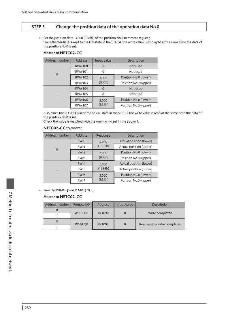
Method of control via CC-Link communication
7 Method of control via industrial netw
ork
280
STEP 5 Change the position data of the operation data No.0
1. Set the position data "3,000 (BB8h)" of the position No.0 to remote register.Since the WR-REQ is kept to the ON-state in the STEP 4, the write value is displayed at the same time the data of the position No.0 is set.
Master to NETC02-CC
Address number Address Input value Description
0
RWw100 0 Not used
RWw101 0 Not used
RWw102 3,000 (BB8h)
Position No.0 (lower)
RWw103 Position No.0 (upper)
1
RWw104 0 Not used
RWw105 0 Not used
RWw106 3,000 (BB8h)
Position No.0 (lower)
RWw107 Position No.0 (upper)
Also, since the RD-REQ is kept to the ON-state in the STEP 3, the write value is read at the same time the data of the position No.0 is set. Check the value is matched with the one having set in the above 1.
NETC02-CC to master
Address number Address Response Description
0
RWr0 5,000 (1388h)
Actual position (lower)
RWr1 Actual position (upper)
RWr2 3,000 (BB8h)
Position No.0 (lower)
RWr3 Position No.0 (upper)
1
RWr4 5,000 (1388h)
Actual position (lower)
RWr5 Actual position (upper)
RWr6 3,000 (BB8h)
Position No.0 (lower)
RWr7 Position No.0 (upper)
2. Turn the WR-REQ and RD-REQ OFF.
Master to NETC02-CC
Address number Remote I/O Address Input value Description
0WR-REQ0 RY1090 0 Write completed
1
0RD-REQ0 RY1092 0 Read and monitor completed
1

Method of control via EtherCAT communication7 M
ethod of control via industrial network
281
3 Method of control via EtherCAT communication
3-1 Guidance
If you are new to the AR Series FLEX built-in controller type, read this section to understand the operating methods along with the operation flow.
STEP1 Installation and connection _ p.282
STEP2 Setting of NETC01-ECT _ p.283 Parameters are enabled after the power is cycled.
STEP3 Setting of driver _ p.285
STEP4 Turn on the power and check the LED _ p.286 Parameters are enabled after the power is cycled.
STEP5 Operation of motor _ p.286
z Operation condition
Here, the motor is supposed to be operated under the following conditions.
•NETC01-ECT node address: 1
•Number of divers connected: 1
•Driver address number: 0
•Driver termination resistor: Enabled
• Before operating the motor, check the condition of the surrounding area to ensure safety. • Before starting guidance, import the ESI file to the EtherCAT Configuration Tool of the PLC and register the PLC configuration in advance. For details about ESI file, contact your nearest Oriental Motor sales office.
The termination resistor for the NETC01-ECT is built into the product. This product can be used without setting the termination resistor.

Method of control via EtherCAT communication
7 Method of control via industrial netw
ork
282
STEP 1 Check the installation and connection
AC power input driver
24 VDCpower supply
RS-485communicationcable
NETC01-ECT
Connect to CN6 or CN7
Mastercontroller
EtherCATcommunicationcable
Driver
Communication cable for the support software *
Connect to CN2
CN1 connector
Connect to + and -
Connect to CN2
Main power supply
Cable for motor *
24 VDCpower supply
GroundingGrounding
Grounding
Required
Required
PC in which the MEXE02 has been installed
* Accessory.
DC power input driver
RS-485 communication cableConnect to CN6 or CN7
NETC01-ECT
Mastercontroller
EtherCATcommunicationcable
Driver
Communication cable for the support software *1
Connect to CN2
24 VDCpower supply
Grounding
Connect to CN1DC powersupply
Connect to CN2
Cable for motor *1 *2Motor cable
Grounding Grounding
PC in which the MEXE02 has been installed
*1 Accessory.*2 Use the cable for motor when the length of the motor cable is not enough.

Method of control via EtherCAT communication 7 M
ethod of control via industrial network
283
STEP 2 Set the parameters and switches of the NETC01-ECT
Set the parameters and switches of the NETC01-ECT.
1. Turn on the power to the NETC01-ECT.At this time, since parameters and switches are not set, the ALARM LED will be lit.Move on the next procedure, and set parameters and switches.
2. Start the MEXE02 and set the parameters.Select the NETC EtherCAT compatible.
3. Set the "Connection (axis #)" parameter of the driver connected to the NETC01-ECT to "enable" using the MEXE02.The initial value in the "Connection (axis #0)" parameter is set to "enable." When the connected driver is one unit and the address number of the driver is "0," it is not required to set the "Connection (axis #)" parameter.
MEXE02 tree view Parameter name Description Initial value
System
Connection (axis #0) Enables the address number of the driver connected to the NETC01-ECT.
[Setting range] Disable Enable
Enable
Connection (axis #1) to
Connection (axis #15)Disable
The inirila value is "enable."
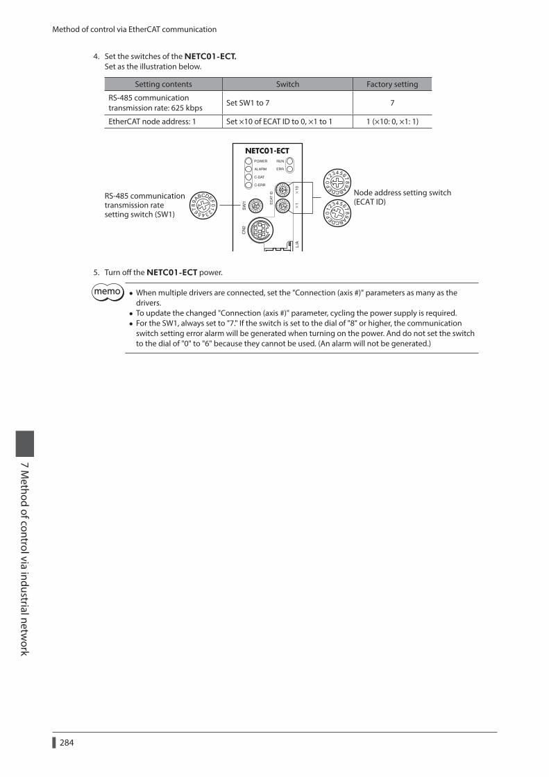
Method of control via EtherCAT communication
7 Method of control via industrial netw
ork
284
4. Set the switches of the NETC01-ECT.Set as the illustration below.
Setting contents Switch Factory setting
RS-485 communication transmission rate: 625 kbps
Set SW1 to 7 7
EtherCAT node address: 1 Set ×10 of ECAT ID to 0, ×1 to 1 1 (×10: 0, ×1: 1)
RS-485 communication transmission ratesetting switch (SW1)
Node address setting switch(ECAT ID)
5. Turn off the NETC01-ECT power.
• When multiple drivers are connected, set the "Connection (axis #)" parameters as many as the drivers.
• To update the changed "Connection (axis #)" parameter, cycling the power supply is required. • For the SW1, always set to "7." If the switch is set to the dial of "8" or higher, the communication switch setting error alarm will be generated when turning on the power. And do not set the switch to the dial of "0" to "6" because they cannot be used. (An alarm will not be generated.)

Method of control via EtherCAT communication 7 M
ethod of control via industrial network
285
STEP 3 Set the switches of the driver
Set the following with the switches of the driver. For the protocol, select "OFF" (network converter).The status becomes as shown in the following figures after setting.
Setting contents AC power input DC power input
Protocol: Network converter Set No.2 of SW4 OFF Set No.2 of SW3 OFF
Address number: 0 Set No.1 of SW4 to OFF, set ID to 0 Set No.1 of SW3 to OFF, set SW1 to 0
Termination resistor: ON Set No.1 and No.2 of TERM. ON Set No.4 of SW3 ON
Transmission rate: 625,000 bps Set SW2 to 7 Set SW2 to 7
For the address number, set the one with the "Connection (axis #)" parameter of the NETC01-ECT set to "enable."
AC power input
Address numbersetting switch (ID)
Termination resistor setting switch (TERM.)
Driver front side Driver bottom side
Transmission ratesetting switch (SW2)
Function setting switch (SW4) No.1: Set the address number. No.2: Set the protocol.
No.2: ONNo.1: ON
No.1: OFFNo.2: OFF
DC power input
Transmission ratesetting switch (SW2)
Address numbersetting switch (SW1)
Function setting switch (SW3) No.1: Set the address number. No.2: Set the protocol. No.3: Not used. No.4: Set the termination resistor.
No.1: OFFNo.2: OFFNo.3: OFFNo.4: ON
Driver front side Driver top side

Method of control via EtherCAT communication
7 Method of control via industrial netw
ork
286
STEP 4 Turn on the power and check the LED
Check that the LED of the driver and NETC01-ECT are as shown in the figure.
Network converter
Green litGreen litOFFOFF
Green litOFF
Green blink
Green litGreen lit
AC power input driver DC power input driver
• When the C-DAT/C-ERR LED (red) of the driver or the C-ERR LED (red) of the NETC01-ECT is lit: Check the transmission rate of RS-485 communication or the address number.
• When the ERR LED (red) of the NETC01-ECT is blink: An EtherCAT communication error has been occurred. Check the error content.
STEP 5 Perform continuous operation via remote I/O of EtherCAT communication
Turn FWD of the address number 0 ON with the remote I/O of EtherCAT communication. Continuous operation for the operation data No.0 is started at the 1,000 Hz of starting speed.Initial values of the remote I/O are as follows.
z Master to NETC01-ECT
CoE Index
Sub-index
Name Type Access Description
2600h
0 − U8 R Number of Sub-index: 2
1I/O
command (lower)
U8 RW
Bit7 Bit6 Bit5 Bit4 Bit3 Bit2 Bit1 Bit0
NET-IN7 NET-IN6 NET-IN5 NET-IN4 NET-IN3 NET-IN2 NET-IN1 NET-IN0
No function FREE STOP HOME START M2 M1 M0
2I/O
command (upper)
U8 RW
Bit7 Bit6 Bit5 Bit4 Bit3 Bit2 Bit1 Bit0
NET-IN15 NET-IN14 NET-IN13 NET-IN12 NET-IN11 NET-IN10 NET-IN9 NET-IN8
RVS FWD −JOG +JOG SSTART MS2 MS1 MS0
STEP 6 Were you able to operate the motor properly?
How did it go? Were you able to operate the motor properly? If the motor does not function, check the following points:
• Is an alarm generated in the driver or NETC01-ECT? • Are the power supply, motor and RS-485 communication cable connected securely? • Are the protocol, address number, transmission rate and termination resistor set correctly? • Is the "Connection (axis #)" parameter of the NETC01-ECT set correctly? • Is the C-DAT LED of NETC01-ECT turned off? Or is the C-ERR LED lit in red? (A RS-485 communication error has
been occurred.) • Is the ERR LED of NETC01-ECT blinks in red? (An EtherCAT communication error has been occurred.) • Is the L/A LED of NETC01-ECT turnde off? Or is it blinks in green? (An EtherCAT communication error has been
occurred.) • Is the motor excited, or is the setting of the excitation method correct? • Are the parameters of the driver set correctly? • Is the operation stop signal input to the driver?

Method of control via EtherCAT communication 7 M
ethod of control via industrial network
287
3-2 Basic operating procedures
This section explains how to perform positioning operation and monitor function as basic operating procedures.This is an example of the operating procedure for controlling via EtherCAT communication using the NETC01-ECT.
Positioning operation
z Setting example • Driver address number (slave address): 0 • Operation data No.1 • Position (travel amount): 5,000 steps
z Operating procedure
1. Send the following remote register to set the position (travel amount) of the operation data No.1 to 5,000 steps.When the TRIG is turned ON, the data set in the remote register is written.
[Remote register command of NETC01-ECT]
CoE IndexSub-Index
Item Type Access Description
2800h (address
number 0)
0 − U8 R Sub-index number: 4
1 Axis U8 RW Reserved (not used)
2 Command U16 RW Command code: 1201h (position of operation data No.1)
3 Data INT32 RW Data: 5,000 (travel amount: 5,000 steps)
4 TRIG U8 RWBit7 Bit6 Bit5 Bit4 Bit3 Bit2 Bit1 Bit0
− − − − − − − TRIG
2. When the data writing is completed properly, the TRIG_R is turned ON. At this time, the STATUS remains OFF.Turn the TRIG OFF again after writing.
[Remote register response of NETC01-ECT]
CoE IndexSub-index
Item Type Access Description
2900h (address
number 0)
0 − U8 R Sub-index number: 4
1 Axis U8 R Reserved (not used)
2 Command U16 R Command code response: 1201h
3 Data INT32 R Data response: 5,000
4 Status U8 RBit7 Bit6 Bit5 Bit4 Bit3 Bit2 Bit1 Bit0
− − − −Command
ErrorAxis Error STATUS TRIG_R
• If the TRIG was turned ON, be sure to turn it OFF again. • When the data is written with the TRIG, the data is saved in the RAM. If the data is saved in the non-volatile memory, execute the "Batch non-volatile memory (3E85h)" of the maintenance command.

Method of control via EtherCAT communication
7 Method of control via industrial netw
ork
288
3. Send the following remote I/O to turn the M0 and START ON (9h).Positioning operation is started. If the motor rotates for 5,000 steps, the positioning operation was successful.
[Remote I/O of NETC01-ECT]
CoE IndexSub-Index
Item Type Access Description
2600h (address
number 0)
0 − U8 R Sub-index number: 2
1I/O
command (lower)
U8 RWBit7 Bit6 Bit5 Bit4 Bit3 Bit2 Bit1 Bit0
NET-IN7 NET-IN6 NET-IN5 NET-IN4 NET-IN3 NET-IN2 NET-IN1 NET-IN0
2I/O
command (upper)
U8 RWBit7 Bit6 Bit5 Bit4 Bit3 Bit2 Bit1 Bit0
NET-IN15 NET-IN14 NET-IN13 NET-IN12 NET-IN11 NET-IN10 NET-IN9 NET-IN8
[NET-IN of AR Series (initial value)]
CoE IndexSub-Index
Item Type Access Description
2600h (address
number 0)
0 − U8 R Sub-index number: 2
1I/O
command (lower)
U8 RWNET-IN7 NET-IN6 NET-IN5 NET-IN4 NET-IN3 NET-IN2 NET-IN1 NET-IN0
No function
FREE STOP HOME START M2 M1 M0
2I/O
command (upper)
U8 RWNET-IN15 NET-IN14 NET-IN13 NET-IN12 NET-IN11 NET-IN10 NET-IN9 NET-IN8
RVS FWD −JOG +JOG SSTART MS2 MS1 MS0
Monitor function
z Setting example • Driver address number (slave address): 0 • Operation data No.0 (the speed was set to 1,000 [Hz]) • Monitor item: Actual speed [r/min] • Connected driver: AR Series
z Operating procedure
1. Send the following remote monitor command to turn the TRIG ON.The monitor of the actual speed [r/min] of the address number 0 is started.
[Remote monitor command of NETC01-ECT]
CoE IndexSub- Index
Item Type Access Description
2A00h (address
number 0)
0 − U8 R Sub-index number: 4
1 Axis U8 RW Address number: 0
2 Command U16 RW Command code: 2067h (monitor of actual speed [r/min])
3 Data INT32 RW Reserved (not used)
4 TRIG U8 RWBit7 Bit6 Bit5 Bit4 Bit3 Bit2 Bit1 Bit0
− − − − − − − TRIG

Method of control via EtherCAT communication 7 M
ethod of control via industrial network
289
2. Send the following remote I/O to turn the FWD (40h) of the address number 0 ON.Continuous operation in the forward direction is started.
[Remote I/O of NETC01-ECT]
CoE IndexSub- Index
Item Type Access Description
2600h (address
number 0)
0 − U8 R Sub-index number: 2
1I/O
command (lower)
U8 RWBit7 Bit6 Bit5 Bit4 Bit3 Bit2 Bit1 Bit0
NET-IN7 NET-IN6 NET-IN5 NET-IN4 NET-IN3 NET-IN2 NET-IN1 NET-IN0
2I/O
command (upper)
U8 RWBit7 Bit6 Bit5 Bit4 Bit3 Bit2 Bit1 Bit0
NET-IN15 NET-IN14 NET-IN13 NET-IN12 NET-IN11 NET-IN10 NET-IN9 NET-IN8
[NET-IN of AR Series (initial value)]
CoE IndexSub- Index
Item Type Access Description
2600h (address
number 0)
0 − U8 R Sub-index number: 2
1I/O
command (lower)
U8 RWNET-IN7 NET-IN6 NET-IN5 NET-IN4 NET-IN3 NET-IN2 NET-IN1 NET-IN0
No function
FREE STOP HOME START M2 M1 M0
2I/O
command (upper)
U8 RWNET-IN15 NET-IN14 NET-IN13 NET-IN12 NET-IN11 NET-IN10 NET-IN9 NET-IN8
RVS FWD −JOG +JOG SSTART MS2 MS1 MS0
3. If the data of the address number 0 is monitored by the remote monitor response, the communication was successful.The TRIG_R is turned ON while the monitor is performed properly. At this time, the STATUS remains OFF.
The monitor is continued to update while the TRIG of the remote monitor command is being ON.
[Remote monitor response of NETC01-ECT]
CoE IndexSub- Index
Item Type Access Description
2B00h (address
number 0)
0 − U8 R Sub-index number: 4
1 Axis U8 R Address number response: 0
2 Command U16 R Command code response: 2067h
3 Data INT32 R Monitor data: 1,000
4 Status U8 RBit7 Bit6 Bit5 Bit4 Bit3 Bit2 Bit1 Bit0
− − − −Command
ErrorAxis Error STATUS TRIG_R
4. Turn the TRIG OFF again to finish the monitor.

Details of remote I/O
7 Method of control via industrial netw
ork
290
4 Details of remote I/O
Remote I/Os are common to all network converters.
4-1 Input signals to the driver
The input signals shown below can be assigned to the NET-IN0 to NET-IN15 of the remote I/O using the parameters.See the table for the assignments of the NET-IN0 to NET-IN15. The value in [ ] is the initial value.For details on parameter, refer to "5-5 User parameters" on p.298.
Bit15 Bit14 Bit13 Bit12 Bit11 Bit10 Bit9 Bit8
NET-IN15 [RVS]
NET-IN14 [FWD]
NET-IN13 [−JOG]
NET-IN12 [+JOG]
NET-IN11 [SSTART]
NET-IN10 [MS2]
NET-IN9 [MS1]
NET-IN8 [MS0]
Bit7 Bit6 Bit5 Bit4 Bit3 Bit2 Bit1 Bit0
NET-IN7 [No function]
NET-IN6 [FREE]
NET-IN5 [STOP]
NET-IN4 [HOME]
NET-IN3 [START]
NET-IN2 [M2]
NET-IN1 [M1]
NET-IN0 [M0]
Signal name Function Setting range
No function Sets when the input terminal is not used. −
FWD Executes continuous operation in the positive direction. 0: Deceleration stop 1: OperationRVS Executes continuous operation in the negative direction.
HOME Executes return-to-home operation.
0: No operation 1: Start operation
START Executes positioning operation.
SSTART Executes sequential positioning operation.
+JOG Executes JOG operation in the positive direction.
−JOG Executes JOG operation in the negative direction.
MS0 to MS5Executes direct positioning operation of the operation data No. set by the I/O parameter.
FREEStops the motor excitation and release the electromagnetic brake.
0: No operation 1: Electromagnetic brake release, motor non-excitation
C-ONSwitches the motor excitation between excitation and non-excitation.
0: Motor non-excitation 1: Motor excitation
STOP Stops of the motor operation.0: No operation 1: Stop operation
ALM-RST * Resets the current alarm.0: No operation 1: Reset alarm
P-PRESET * Executes position preset.0: No operation 1: Execute preset
P-CLR * Resets the absolute position error alarm.0: No operation 1: Reset alarm
HMIReleases of the function limitation of the MEXE02 or OPX-2A.
0: Function limitation 1: Function limitation release
R0 to R15General signals. Use these signals when controlling the system via RS-485 communication.
0: OFF 1: ON
M0 to M5Selects the operation data No. using these six bits. See p.93 for details on the combination.
0: OFF 1: ON (Operation data Nos.0 to 63 can be selected.)
* It cannot be set in the driver that is before the specification change. Refer to p.7 for details.

Details of remote I/O7 M
ethod of control via industrial network
291
• Do not assign the same input signal to multiple input terminals. When the same input signal is assigned to multiple input terminals, the function will be executed if any of the terminals becomes active.
• The ALM-RST input and P-CLR input will be executed when turning from ON (1) to OFF (0). The P-PRESET input will be executed when turning from OFF (0) to ON (1).
• When the C-ON input and HMI input are not assigned to the input terminals, these inputs will always be set to ON (1). When assigning to both direct I/O and remote I/O, the function will be executed when both of them are set to ON (1).
4-2 Output signals from the driver
The output signals shown below can be assigned to the NET-OUT0 to NET-OUT15 of the remote I/O using the parameters.See the table for the assignments of the NET-OUT0 to NET-OUT15. The value in [ ] is the initial value.For details on parameter, refer to "5-5 User parameters" on p.298.
Bit15 Bit14 Bit13 Bit12 Bit11 Bit10 Bit9 Bit8
NET-OUT15 [TLC]
NET-OUT14 [END]
NET-OUT13 [MOVE]
NET-OUT12 [TIM]
NET-OUT11 [AREA3]
NET-OUT10 [AREA2]
NET-OUT9 [AREA1]
NET-OUT8 [S-BSY]
Bit7 Bit6 Bit5 Bit4 Bit3 Bit2 Bit1 Bit0
NET-OUT7 [ALM]
NET-OUT6 [WNG]
NET-OUT5 [READY]
NET-OUT4 [HOME-P]
NET-OUT3 [START_R]
NET-OUT2 [M2_R]
NET-OUT1 [M1_R]
NET-OUT0 [M0_R]
Signal name Function Data read
No function Sets when the output terminal is not used. −
FWD_R Outputs in response to the FWD input.
0: OFF 1: ON
RVS_R Outputs in response to the RVS input.
HOME_R Outputs in response to the HOME input.
START_R Outputs in response to the START input.
SSTART_R Outputs in response to the SSTART input.
+JOG_R Outputs in response to the +JOG input.
−JOG_R Outputs in response to the −JOG input.
MS0_R to MS5_R Outputs in response to the MS0 to MS5 input.
FREE_R Outputs in response to the FREE input.
C-ON_R Outputs in response to the C-ON input.
STOP_R Outputs in response to the STOP input.
R0 to R15 Outputs the status of the general signal R0 to R15.
M0_R to M5_R Outputs in response to the M0 to M5 input.
+LS_R Outputs in response to the +LS input.
−LS_R Outputs in response to the −LS input.
HOMES_R Outputs in response to the HOMES input.
SLIT_R Outputs in response to the SLIT input.
ALM Outputs the alarm status of the driver (normally open).0: Alarm not present 1: Alarm present
WNG Outputs the warning status of the driver.0: Warning not present 1: Warning present
READY Outputs when the driver is ready.0: Not ready 1: Ready
MOVE Outputs while the motor operates.0: Motor stopped 1: Motor operating
END Outputs when the positioning operation is completed.0: Motor operating 1: Motor operating completion

Details of remote I/O
7 Method of control via industrial netw
ork
292
Signal name Function Data read
HOME-P Outputs when the motor is in home position.0: Not home position 1: Home position
TLC Outputs when the load is outside of the motor torque range.0: Inside torque range 1: Outside torque range
TIM Outputs once every 7.2° rotation of the motor Outputs shaft.0: OFF 1: ON
AREA1 to AREA3 Outputs when the motor is within the area.0: Outside area 1: Inside area
S-BSY Outputs when the driver is in internal processing state.0: OFF 1: ON
MPS * Outputs while the driver main power is on.0: OFF 1: ON
* AC power input only
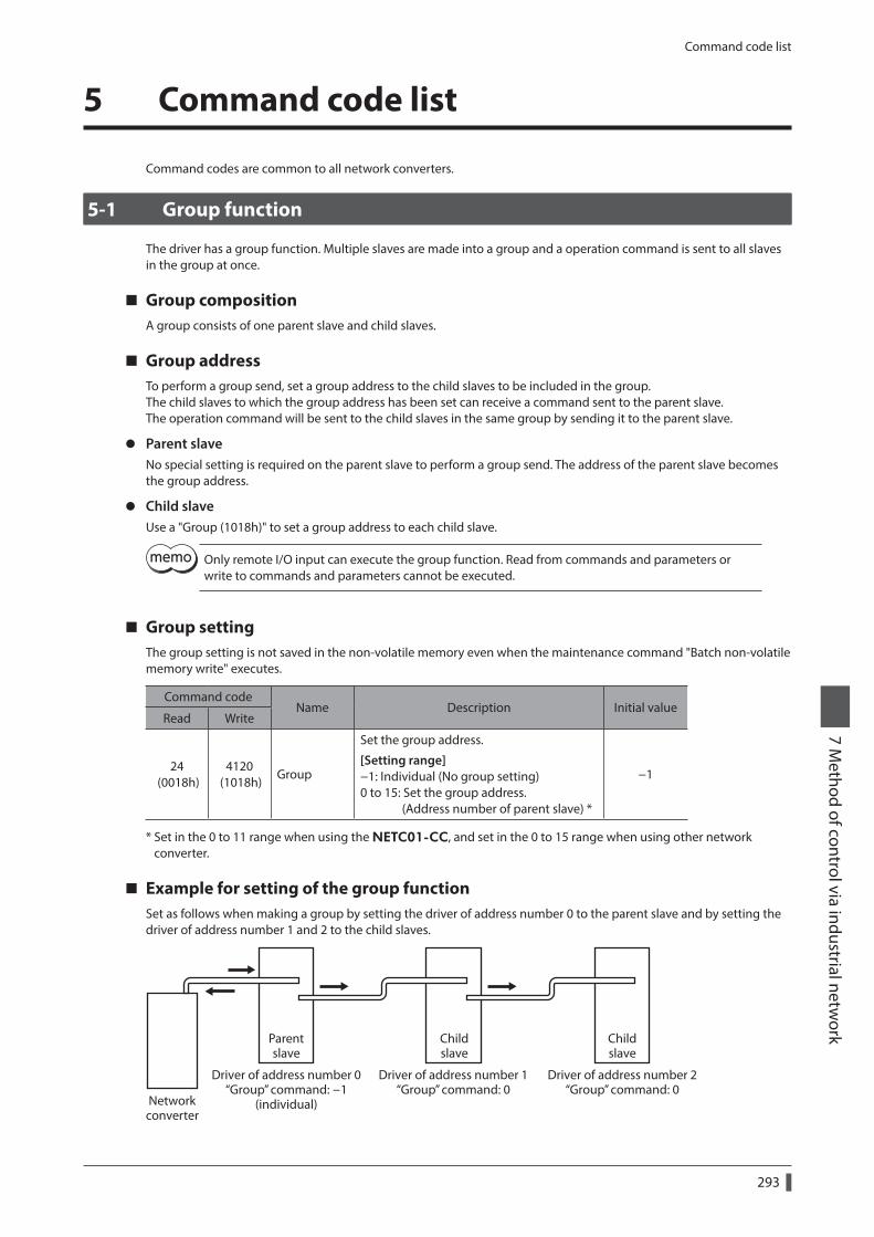
Command code list7 M
ethod of control via industrial network
293
5 Command code list
Command codes are common to all network converters.
5-1 Group function
The driver has a group function. Multiple slaves are made into a group and a operation command is sent to all slaves in the group at once.
Group compositionA group consists of one parent slave and child slaves.
Group addressTo perform a group send, set a group address to the child slaves to be included in the group.The child slaves to which the group address has been set can receive a command sent to the parent slave.The operation command will be sent to the child slaves in the same group by sending it to the parent slave.
z Parent slaveNo special setting is required on the parent slave to perform a group send. The address of the parent slave becomes the group address.
z Child slaveUse a "Group (1018h)" to set a group address to each child slave.
Only remote I/O input can execute the group function. Read from commands and parameters or write to commands and parameters cannot be executed.
Group settingThe group setting is not saved in the non-volatile memory even when the maintenance command "Batch non-volatile memory write" executes.
Command codeName Description Initial value
Read Write
24 (0018h)
4120 (1018h)
Group
Set the group address.
[Setting range] −1: Individual (No group setting) 0 to 15: Set the group address. (Address number of parent slave) *
−1
* Set in the 0 to 11 range when using the NETC01-CC, and set in the 0 to 15 range when using other network converter.
Example for setting of the group functionSet as follows when making a group by setting the driver of address number 0 to the parent slave and by setting the driver of address number 1 and 2 to the child slaves.
Networkconverter
Driver of address number 0“Group” command: -1
(individual)
Driver of address number 1“Group” command: 0
Driver of address number 2“Group” command: 0
Parentslave
Childslave
Childslave

Command code list
7 Method of control via industrial netw
ork
294
This is a timing chart for when assigning the START to NET-IN3 (remote I/O) of the driver in the group.
Address number 0NET-IN3=ON
Motor operation at address number 0 (parent slave)
“Group” command: -1
Motor operation at address number 1 (child slave)
“Group” command: 0
Motor operation at address number 2 (child slave)
“Group” command: 0
Network converter to slave
When inputting a remote I/O to the parent slave, the motors of the parent slave and child slaves will operate. The motors will not operate if the remote I/O is input to the child slaves.
5-2 Maintenance command
These commands are used to clear the alarm records and warning records. They are also used to execute the batch processing for the non-volatile memory.
Command code
Name Description Setting range
12480 (30C0h)
Reset alarmResets the alarms that are present. Some alarms cannot be reset with the “reset alarm.”
1: Execute
12481 (30C1h)
Absolute position error alarm reset
Resets the absolute position error alarm. Since this alarm is the dedicated alarm for the absolute position error, other alarms cannot be reset.
12482 (30C2h)
Clear alarm records Clears alarm records.
12483 (30C3h)
Clear warning records Clears warning records.
12484 (30C4h)
Clear communication error records
Clears communication error records.
12485 (30C5h)
P-PRESET executeUpdates the command position to the value of the "Preset position" parameter.
12486 (30C6h)
Configuration Executes the parameter recalculation and the setup.
12487 (30C7h)
All data initialization
Resets the operation data and parameters saved in the non-volatile memory to the initial value. Note that “Communication parity”, “Communication stop bit”, and “Transmission waiting time” parameters are not initialized.
12488 (30C8h)
Batch non-volatile memory read
Reads the operation data and parameters saved in the non-volatile memory, to the RAM. All operation data and parameters previously saved in the RAM are overwritten.
12489 (30C9h)
Batch non-volatile memory write
Writes the operation data and parameters saved in the RAM to the non-volatile memory.
The non-volatile memory can be rewritten approximately 100,000 times.

Command code list7 M
ethod of control via industrial network
295
5-3 Monitor command
These commands are used to monitor the driver condition.
Command code
Name Description
8256 (2040h)
Present alarm Monitors the present alarm code.
8257 (2041h)
Alarm record 1
Monitors the alarm records 1 to 10.
8258 (2042h)
Alarm record 2
8259 (2043h)
Alarm record 3
8260 (2044h)
Alarm record 4
8261 (2045h)
Alarm record 5
8262 (2046h)
Alarm record 6
8263 (2047h)
Alarm record 7
8264 (2048h)
Alarm record 8
8265 (2049h)
Alarm record 9
8266 (204Ah)
Alarm record 10
8267 (204Bh)
Present warning Monitors the present warning code.
8268 (204Ch)
Warning record 1
Monitors the warning records 1 to 10.
8269 (204Dh)
Warning record 2
8270 (204Eh)
Warning record 3
8271 (204Fh)
Warning record 4
8272 (2050h)
Warning record 5
8273 (2051h)
Warning record 6
8274 (2052h)
Warning record 7
8275 (2053h)
Warning record 8
8276 (2054h)
Warning record 9
8277 (2055h)
Warning record 10
8279 (2057h)
Communication error code record 1
Monitors the communication error records 1 to 3 that have occurred in the past.
8280 (2058h)
Communication error code record 2
8281 (2059h)
Communication error code record 3

Command code list
7 Method of control via industrial netw
ork
296
Command code
Name Description
8282 (205Ah)
Communication error code record 4
Monitors the communication error records 4 to 10 that have occurred in the past.
8283 (205Bh)
Communication error code record 5
8284 (205Ch)
Communication error code record 6
8285 (205Dh)
Communication error code record 7
8286 (205Eh)
Communication error code record 8
8287 (205Fh)
Communication error code record 9
8288 (2060h)
Communication error code record 10
8289 (2061h)
Present selected data No. Monitors the operation data No. currently selected.
8290 (2062h)
Present operation data No.
Monitors the operation data No. corresponding to the data used in the current positioning operation. This address is used in linked-motion operation and sequential positioning operation. While the motor is stopped, the last used operation data number is indicated.
8291 (2063h)
Command position Monitors the command position.
8292 (2064h)
Command speed Monitors the current command speed. (r/min)
8294 (2066h)
Actual position Monitors the actual position.
8295 (2067h)
Actual speed Monitors the actual speed. (r/min)
8297 (2069h)
Remaining dwell timeMonitors how much of the dwell time used in the linked-motion 2 operation remains.
8298 (206Ah)
Direct I/O and electromagnetic brake status
Monitors the each direct I/O signal and electromagnetic brake status. See the following table for the assignments.
Direct I/O and electromagnetic brake status [8298 (206Ah)]
Byte Bit7 Bit6 Bit5 Bit4 Bit3 Bit2 Bit1 Bit0
0 IN1 IN0 − − SLIT HOMES −LS +LS
1 − − IN7 IN6 IN5 IN4 IN3 IN2
2 − − OUT5 OUT4 OUT3 OUT2 OUT1 OUT0
3 − − − − − − − MB

Command code list7 M
ethod of control via industrial network
297
5-4 Operation data
Up to 64 operation data can be set (data Nos.0 to 63).When the operation data is changed, a recalculation and setup will be performed after the operation is stopped and the changed value will be update.
Command codeName Setting range
Initial valueRead Write
512 (0200h)
to 575
(023Fh)
4608 (1200h)
to 4671
(123Fh)
Position No.0 to
Position No.63−8,388,608 to 8,388,607 step 0
576 (0240h)
to 639
(027Fh)
4672 (1240h)
to 4735
(127Fh)
Operating speed No.0 to
Operating speed No.630 to 1,000,000 Hz 1,000
640 (0280h)
to 703
(02BFh)
4736 (1280h)
to 4799
(12BFh)
Operation mode No.0 to
Operation mode No.63
0: Incremental 1: Absolute
0
704 (02C0h)
to 767
(02FFh)
4800 (12C0h)
to 4863
(12FFh)
Operation function No.0 to
Operation function No.63
0: Single-motion 1: Linked-motion 2: Linked-motion 2 3: Push
0
768 (0300h)
to 831
(033Fh)
4864 (1300h)
to 4927
(133Fh)
Acceleration No.0 to
Acceleration No.63
1 to 1,000,000 (1=0.001 ms/kHz or 1=0.001 s) *1 *2
1,000
832 (0340h)
to 895
(037Fh)
4928 (1340h)
to 4991
(137Fh)
Deceleration No.0 to
Deceleration No.63
1 to 1,000,000 (1=0.001 ms/kHz or 1=0.001 s) *1 *2
1,000
896 (0380h)
to 959
(03BFh)
4992 (1380h)
to 5055
(13BFh)
Push current No.0 to
Push current No.630 to 1,000 (1=0.1%) *3 200
960 (03C0h)
to 1023
(03FFh)
5056 (13C0h)
to 5119
(13FFh)
Sequential positioning No.0 to
Sequential positioning No.63
0: Disable 1: Enable
0
1024 (0400h)
to 1087
(043Fh)
5120 (1400h)
to 5183
(143Fh)
Dwell time No.0 to
Dwell time No.630 to 50,000 (1=0.001 s) 0
*1 This item is effective when the “Acceleration/deceleration type” parameter is set to “separate.” If this parameter is set to “common”, the values of the "Common acceleration” and "Common deceleration” parameters will be used (initial value: separate).
*2 Acceleration/deceleration rate (ms/kHz) or acceleration/deceleration time (s) can be selected using "Acceleration/deceleration unit" parameter. (initial value: acceleration/deceleration rate).
*3 For the driver which is before the specification change, the setting range is 0 to 500 (1=0.1%). Refer to p.7 for details.
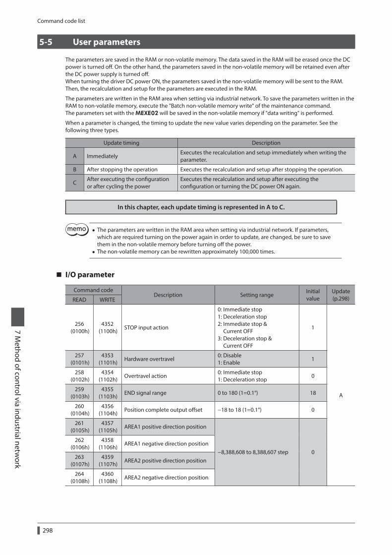
Command code list
7 Method of control via industrial netw
ork
298
5-5 User parameters
The parameters are saved in the RAM or non-volatile memory. The data saved in the RAM will be erased once the DC power is turned off. On the other hand, the parameters saved in the non-volatile memory will be retained even after the DC power supply is turned off.When turning the driver DC power ON, the parameters saved in the non-volatile memory will be sent to the RAM. Then, the recalculation and setup for the parameters are executed in the RAM.
The parameters are written in the RAM area when setting via industrial network. To save the parameters written in the RAM to non-volatile memory, execute the "Batch non-volatile memory write" of the maintenance command.The parameters set with the MEXE02 will be saved in the non-volatile memory if "data writing" is performed.
When a parameter is changed, the timing to update the new value varies depending on the parameter. See the following three types.
Update timing Description
A ImmediatelyExecutes the recalculation and setup immediately when writing the parameter.
B After stopping the operation Executes the recalculation and setup after stopping the operation.
CAfter executing the configuration or after cycling the power
Executes the recalculation and setup after executing the configuration or turning the DC power ON again.
In this chapter, each update timing is represented in A to C.
• The parameters are written in the RAM area when setting via industrial network. If parameters, which are required turning on the power again in order to update, are changed, be sure to save them in the non-volatile memory before turning off the power.
• The non-volatile memory can be rewritten approximately 100,000 times.
I/O parameter
Command codeDescription Setting range
Initial value
Update (p.298)READ WRITE
256 (0100h)
4352 (1100h)
STOP input action
0: Immediate stop 1: Deceleration stop 2: Immediate stop & Current OFF 3: Deceleration stop & Current OFF
1
A
257 (0101h)
4353 (1101h)
Hardware overtravel0: Disable 1: Enable
1
258 (0102h)
4354 (1102h)
Overtravel action0: Immediate stop 1: Deceleration stop
0
259 (0103h)
4355 (1103h)
END signal range 0 to 180 (1=0.1°) 18
260 (0104h)
4356 (1104h)
Position complete output offset −18 to 18 (1=0.1°) 0
261 (0105h)
4357 (1105h)
AREA1 positive direction position
−8,388,608 to 8,388,607 step 0
262 (0106h)
4358 (1106h)
AREA1 negative direction position
263 (0107h)
4359 (1107h)
AREA2 positive direction position
264 (0108h)
4360 (1108h)
AREA2 negative direction position

Command code list7 M
ethod of control via industrial network
299
Command codeDescription Setting range
Initial value
Update (p.298)READ WRITE
265 (0109h)
4361 (1109h)
AREA3 positive direction position−8,388,608 to 8,388,607 step 0
A266
(010Ah)4362
(110Ah)AREA3 negative direction position
267 (010Bh)
4363 (110Bh)
Minimum ON time for MOVE output
0 to 255 ms 0
268 (010Ch)
4364 (110Ch)
LS contact configration
0: Make (N.O.) 1: Brake (N.C.)
0 C269
(010Dh)4365
(110Dh)HOMES logic level
270 (010Eh)
4366 (110Eh)
SLIT logic level
2048 (0800h)
6144 (1800h)
MS0 operation No. selection
0 to 63
0
B
2049 (0801h)
6145 (1801h)
MS1 operation No. selection 1
2050 (0802h)
6146 (1802h)
MS2 operation No. selection 2
2051 (0803h)
6147 (1803h)
MS3 operation No. selection 3
2052 (0804h)
6148 (1804h)
MS4 operation No. selection 4
2053 (0805h)
6149 (1805h)
MS5 operation No. selection 5
2054 (0806h)
6150 (1806h)
HOME-P output function selection0: Home output 1: Return-to-home complete output
0 A
Motor parameter
Command codeDescription Setting range
Initial value
Update (p.298)READ WRITE
288 (0120h)
4384 (1120h)
RUN current 0 to 1,000 (1=0.1%) 1,000
A
289 (0121h)
4385 (1121h)
STOP current 0 to 500 (1=0.1%) 500
290 (0122h)
4386 (1122h)
Position loop gain 1 to 50 10
291 (0123h)
4387 (1123h)
Speed loop gain 10 to 200 180
292 (0124h)
4388 (1124h)
Speed loop integral time constant 100 to 2,000 (1=0.1 ms) 1,000
293 (0125h)
4389 (1125h)
Speed filter 0 to 200 ms 1B
294 (0126h)
4390 (1126h)
Moving average time 1 to 200 ms 1
2064 (0810h)
6160 (1810h)
Filter selection0: Speed filter 1: Moving average filter
0 C
2065 (0811h)
6161 (1811h)
Speed difference gain 1 0 to 500 45A
2066 (0812h)
6162 (1812h)
Speed difference gain 2 0 to 500 45
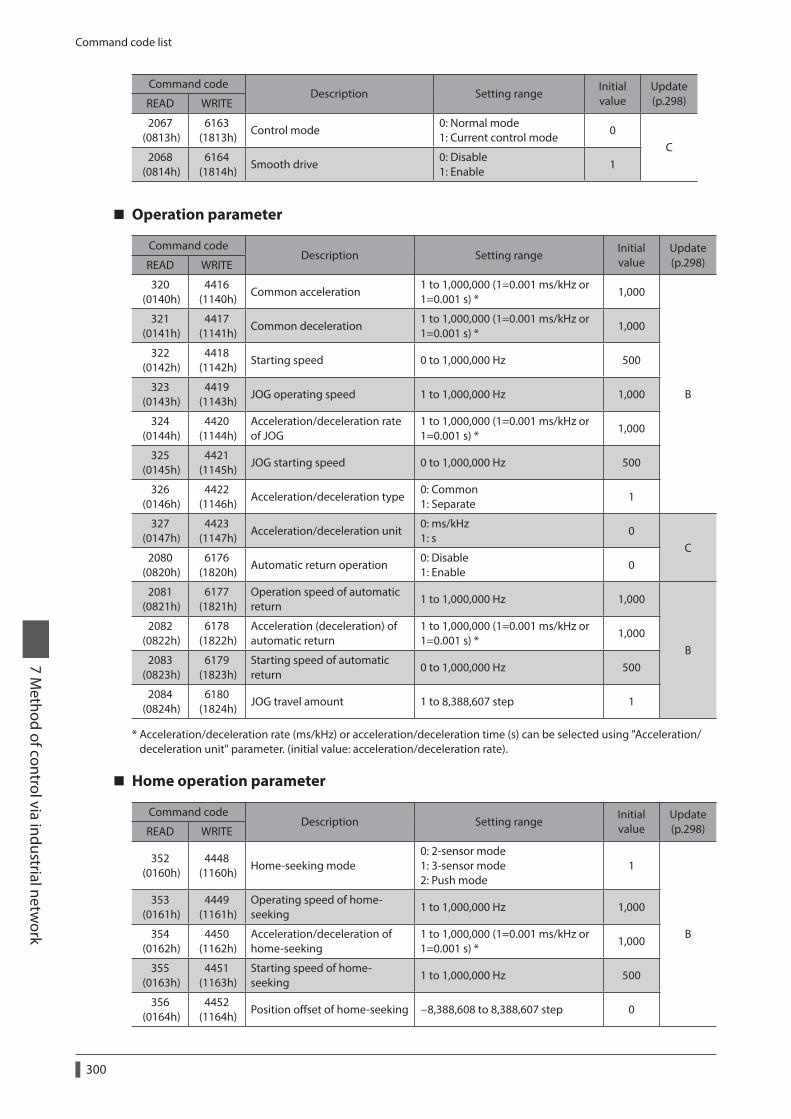
Command code list
7 Method of control via industrial netw
ork
300
Command codeDescription Setting range
Initial value
Update (p.298)READ WRITE
2067 (0813h)
6163 (1813h)
Control mode0: Normal mode 1: Current control mode
0C
2068 (0814h)
6164 (1814h)
Smooth drive0: Disable 1: Enable
1
Operation parameter
Command codeDescription Setting range
Initial value
Update (p.298)READ WRITE
320 (0140h)
4416 (1140h)
Common acceleration 1 to 1,000,000 (1=0.001 ms/kHz or 1=0.001 s) *
1,000
B
321 (0141h)
4417 (1141h)
Common deceleration 1 to 1,000,000 (1=0.001 ms/kHz or 1=0.001 s) *
1,000
322 (0142h)
4418 (1142h)
Starting speed 0 to 1,000,000 Hz 500
323 (0143h)
4419 (1143h)
JOG operating speed 1 to 1,000,000 Hz 1,000
324 (0144h)
4420 (1144h)
Acceleration/deceleration rate of JOG
1 to 1,000,000 (1=0.001 ms/kHz or 1=0.001 s) *
1,000
325 (0145h)
4421 (1145h)
JOG starting speed 0 to 1,000,000 Hz 500
326 (0146h)
4422 (1146h)
Acceleration/deceleration type0: Common 1: Separate
1
327 (0147h)
4423 (1147h)
Acceleration/deceleration unit0: ms/kHz 1: s
0C
2080 (0820h)
6176 (1820h)
Automatic return operation0: Disable 1: Enable
0
2081 (0821h)
6177 (1821h)
Operation speed of automatic return
1 to 1,000,000 Hz 1,000
B
2082 (0822h)
6178 (1822h)
Acceleration (deceleration) of automatic return
1 to 1,000,000 (1=0.001 ms/kHz or 1=0.001 s) *
1,000
2083 (0823h)
6179 (1823h)
Starting speed of automatic return
0 to 1,000,000 Hz 500
2084 (0824h)
6180 (1824h)
JOG travel amount 1 to 8,388,607 step 1
* Acceleration/deceleration rate (ms/kHz) or acceleration/deceleration time (s) can be selected using "Acceleration/deceleration unit" parameter. (initial value: acceleration/deceleration rate).
Home operation parameter
Command codeDescription Setting range
Initial value
Update (p.298)READ WRITE
352 (0160h)
4448 (1160h)
Home-seeking mode0: 2-sensor mode 1: 3-sensor mode 2: Push mode
1
B
353 (0161h)
4449 (1161h)
Operating speed of home-seeking
1 to 1,000,000 Hz 1,000
354 (0162h)
4450 (1162h)
Acceleration/deceleration of home-seeking
1 to 1,000,000 (1=0.001 ms/kHz or 1=0.001 s) *
1,000
355 (0163h)
4451 (1163h)
Starting speed of home-seeking
1 to 1,000,000 Hz 500
356 (0164h)
4452 (1164h)
Position offset of home-seeking −8,388,608 to 8,388,607 step 0

Command code list7 M
ethod of control via industrial network
301
Command codeDescription Setting range
Initial value
Update (p.298)READ WRITE
357 (0165h)
4453 (1165h)
Starting direction of home-seeking
0: Negative direction 1: Positive direction
1
B
358 (0166h)
4454 (1166h)
SLIT detection with home-seeking
0: Disable 1: Enable
0
359 (0167h)
4455 (1167h)
TIM signal detection with home-seeking
0: Disable 1: Enable
0
360 (0168h)
4456 (1168h)
Operating current of home-seeking with push-motion
0 to 1,000 (1=0.1%) 1,000
* Acceleration/deceleration rate (ms/kHz) or acceleration/deceleration time (s) can be selected using "Acceleration/deceleration unit" parameter. (initial value: acceleration/deceleration rate).
Alarm parameter
Command codeDescription Setting range
Initial value
Update (p.298)READ WRITE
384 (0180h)
4480 (1180h)
Overload alarm 1 to 300 (1=0.1 s) 50A
385 (0181h)
4481 (1181h)
Excessive position deviation alarm at current ON
1 to 30,000 (1=0.01 rev) 300
388 (0184h)
4484 (1184h)
Return-to-home incomplete alarm0: Disable 1: Enable
0 C
2112 (0840h)
6208 (1840h)
Excessive position deviation alarm at current OFF
1 to 30,000 (1=0.01 rev) 10,000 A
Warning parameter
Command codeDescription Setting range Initial value
Update (p.298)READ WRITE
416 (01A0h)
4512 (11A0h)
Overheat warning 40 to 85 °C 85
A
417 (01A1h)
4513 (11A1h)
Overload warning 1 to 300 (1=0.1 s) 50
418 (01A2h)
4514 (11A2h)
Overspeed warning 1 to 5,000 r/min 4,500
419 (01A3h)
4515 (11A3h)
Overvoltage warning
•AC power input: 120 to 450 V
•DC power input: 150 to 630 (1=0.1 V)
AC power input: 435 DC power input: 630
420 (01A4h)
4516 (11A4h)
Undervoltage warning
•AC power input: 120 to 280 V
•DC power input: 150 to 630 (1=0.1 V)
AC power input: 120 DC power input: 180
421 (01A5h)
4517 (11A5h)
Excessive position deviation warning at current ON
1 to 30,000 (1=0.01 rev) 300

Command code list
7 Method of control via industrial netw
ork
302
Coordinates parameter
Command codeDescription Setting range Initial value
Update (p.298)READ WRITE
448 (01C0h)
4544 (11C0h)
Electronic gear A 1 to 65,535 1
C449
(01C1h)4545
(11C1h)Electronic gear B 1 to 65,535 1
450 (01C2h)
4546 (11C2h)
Motor rotation direction0: Positive direction=CCW 1: Positive direction=CW
1
451 (01C3h)
4547 (11C3h)
Software overtravel0: Disable 1: Enable
1
A
452 (01C4h)
4548 (11C4h)
Positive software limit −8,388,608 to 8,388,607 step 8,388,607
453 (01C5h)
4549 (11C5h)
Negative software limit −8,388,608 to 8,388,607 step −8,388,608
454 (01C6h)
4550 (11C6h)
Preset position −8,388,608 to 8,388,607 step 0
455 (01C7h)
4551 (11C7h)
Wrap setting0: Disable 1: Enable
0C
456 (01C8h)
4552 (11C8h)
Wrap setting range 1 to 8,388,607 step 1,000
Common parameter
Command codeDescription Setting range
Initial value
Update (p.298)READ WRITE
480 (01E0h)
4576 (11E0h)
Data setter speed display0: Signed 1: Absolute value
0A
481 (01E1h)
4577 (11E1h)
Data setter edit0: Disable 1: Enable
1
482 (01E2h)
4578 (11E2h)
Absolute back-up system0: Disable 1: Enable
0 C
I/O function [Input] parameter
Command codeDescription Setting range Initial value
Update (p.298)READ WRITE
2176 (0880h)
6272 (1880h)
IN0 input function selection
Refer to table next.
3: HOME
C
2177 (0881h)
6273 (1881h)
IN1 input function selection 4: START
2178 (0882h)
6274 (1882h)
IN2 input function selection 48: M0
2179 (0883h)
6275 (1883h)
IN3 input function selection 49: M1
2180 (0884h)
6276 (1884h)
IN4 input function selection 50: M2
2181 (0885h)
6277 (1885h)
IN5 input function selection 16: FREE
2182 (0886h)
6278 (1886h)
IN6 input function selection 18: STOP
2183 (0887h)
6279 (1887h)
IN7 input function selection 24: ALM-RST

Command code list7 M
ethod of control via industrial network
303
Command codeDescription Setting range Initial value
Update (p.298)READ WRITE
2192 (0890h)
6288 (1890h)
IN0 input logic level setting
0: Make (N.O) 1: Brake (N.C.)
0 C
2193 (0891h)
6289 (1891h)
IN1 input logic level setting
2194 (0892h)
6290 (1892h)
IN2 input logic level setting
2195 (0893h)
6291 (1893h)
IN3 input logic level setting
2196 (0894h)
6292 (1894h)
IN4 input logic level setting
2197 (0895h)
6293 (1895h)
IN5 input logic level setting
2198 (0896h)
6294 (1896h)
IN6 input logic level setting
2199 (0897h)
6295 (1897h)
IN7 input logic level setting
Setting range for IN input function selection
0: No function 1: FWD 2: RVS 3: HOME 4: START 5: SSTART 6: +JOG 7: −JOG
8: MS0 9: MS1 10: MS2 11: MS3 12: MS4 13: MS5 16: FREE 17: C-ON
18: STOP 24: ALM-RST 25: P-PRESET 26: P-CLR 27: HMI 32: R0 33: R1 34: R2
35: R3 36: R4 37: R5 38: R6 39: R7 40: R8 41: R9 42: R10
43: R11 44: R12 45: R13 46: R14 47: R15 48: M0 49: M1 50: M2
51: M3 52: M4 53: M5
I/O function [Output] parameter
Command codeDescription Setting range Initial value
Update (p.298)READ WRITE
2208 (08A0h)
6304 (18A0h)
OUT0 output function selection
Refer to table next.
70: HOME-P
C
2209 (08A1h)
6305 (18A1h)
OUT1 output function selection 69: END
2210 (08A2h)
6306 (18A2h)
OUT2 output function selection 73: AREA1
2211 (08A3h)
6307 (18A3h)
OUT3 output function selection 67: READY
2212 (08A4h)
6308 (18A4h)
OUT4 output function selection 66: WNG
2213 (08A5h)
6309 (18A5h)
OUT5 output function selection 65: ALM
Setting range for OUT output function selection
0: No function 1: FWD_R 2: RVS_R 3: HOME_R 4: START_R 5: SSTART_R 6: +JOG_R 7: −JOG_R 8: MS0_R 9: MS1_R
10: MS2_R 11: MS3_R 12: MS4_R 13: MS5_R 16: FREE_R 17: C-ON_R 18: STOP_R 32: R0 33: R1 34: R2
35: R3 36: R4 37: R5 38: R6 39: R7 40: R8 41: R9 42: R10 43: R11 44: R12
45: R13 46: R14 47: R15 48: M0_R 49: M1_R 50: M2_R 51: M3_R 52: M4_R 53: M5_R 60: +LS_R
61: −LS_R 62: HOMES_R 63: SLIT_R 65: ALM 66: WNG 67: READY 68: MOVE 69: END 70: HOME-P 71: TLC
72: TIM 73: AREA1 74: AREA2 75: AREA3 80: S-BSY 82: MPS *
* AC power input only.

Command code list
7 Method of control via industrial netw
ork
304
I/O function [RS-485] parameter
Command codeDescription Setting range Initial value
Update (p.298)READ WRITE
2224 (08B0h)
6320 (18B0h)
NET-IN0 input function selection
Refer to "Setting range for NET-IN input function selection" on p.305.
48: M0
C
2225 (08B1h)
6321 (18B1h)
NET-IN1 input function selection 49: M1
2226 (08B2h)
6322 (18B2h)
NET-IN2 input function selection 50: M2
2227 (08B3h)
6323 (18B3h)
NET-IN3 input function selection 4: START
2228 (08B4h)
6324 (18B4h)
NET-IN4 input function selection 3: HOME
2229 (08B5h)
6325 (18B5h)
NET-IN5 input function selection 18: STOP
2230 (08B6h)
6326 (18B6h)
NET-IN6 input function selection 16: FREE
2231 (08B7h)
6327 (18B7h)
NET-IN7 input function selection 0: No function
2232 (08B8h)
6328 (18B8h)
NET-IN8 input function selection 8: MS0
2233 (08B9h)
6329 (18B9h)
NET-IN9 input function selection 9: MS1
2234 (08BAh)
6330 (18BAh)
NET-IN10 input function selection 10: MS2
2235 (08BBh)
6331 (18BBh)
NET-IN11 input function selection 5: SSTART
2236 (08BCh)
6332 (18BCh)
NET-IN12 input function selection 6: +JOG
2237 (08BDh)
6333 (18BDh)
NET-IN13 input function selection 7: −JOG
2238 (08BEh)
6334 (18BEh)
NET-IN14 input function selection 1: FWD
2239 (08BFh)
6335 (18BFh)
NET-IN15 input function selection 2: RVS
2240 (08C0h)
6336 (18C0h)
NET-OUT0 output function selection
Refer to "Setting range for NET-OUT output function selection" on p.305.
48: M0_R
C
2241 (08C1h)
6337 (18C1h)
NET-OUT1 output function selection
49: M1_R
2242 (08C2h)
6338 (18C2h)
NET-OUT2 output function selection
50: M2_R
2243 (08C3h)
6339 (18C3h)
NET-OUT3 output function selection
4: START_R
2244 (08C4h)
6340 (18C4h)
NET-OUT4 output function selection
70: HOME-P
2245 (08C5h)
6341 (18C5h)
NET-OUT5 output function selection
67: READY
2246 (08C6h)
6342 (18C6h)
NET-OUT6 output function selection
66: WNG
2247 (08C7h)
6343 (18C7h)
NET-OUT7 output function selection
65: ALM
2248 (08C8h)
6344 (18C8h)
NET-OUT8 output function selection
80: S-BSY
2249 (08C9h)
6345 (18C9h)
NET-OUT9 output function selection
73: AREA1
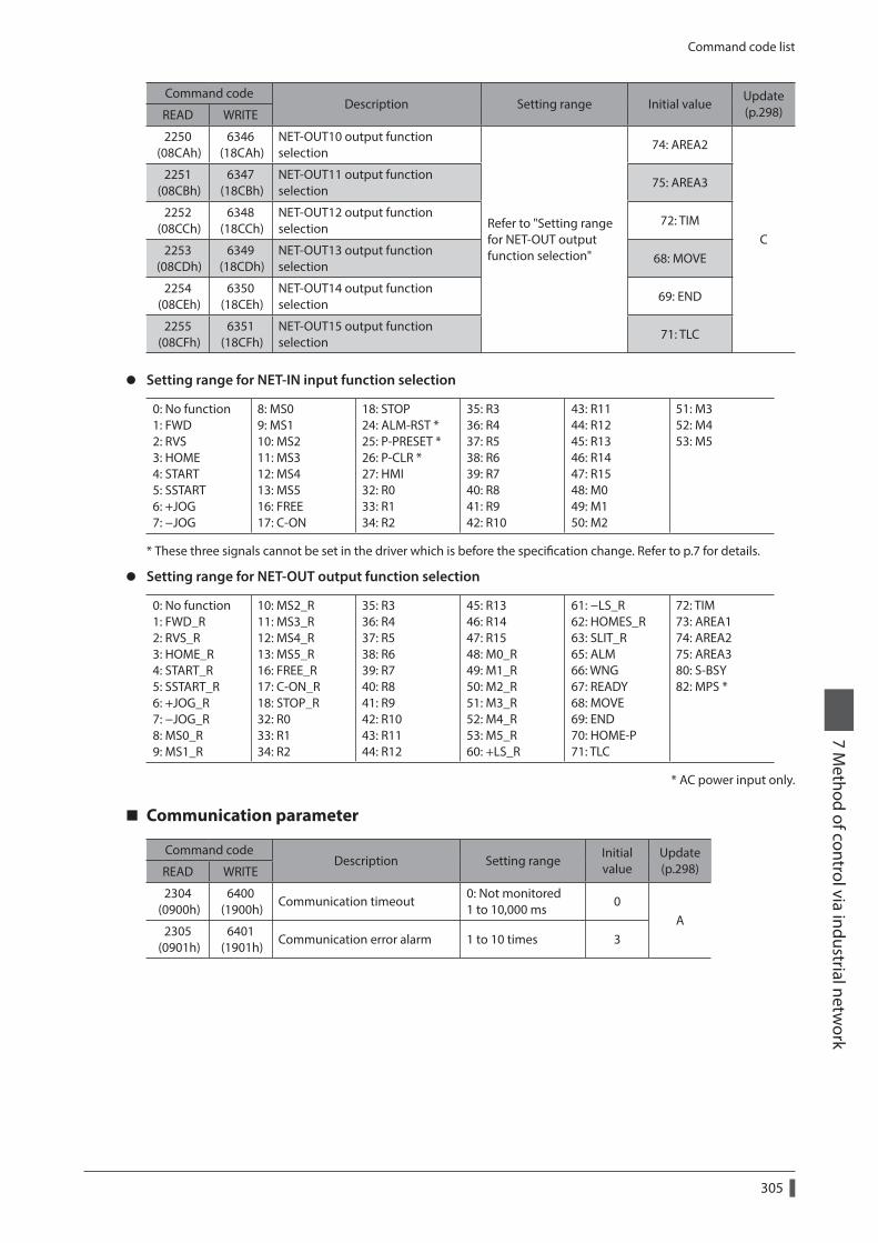
Command code list7 M
ethod of control via industrial network
305
Command codeDescription Setting range Initial value
Update (p.298)READ WRITE
2250 (08CAh)
6346 (18CAh)
NET-OUT10 output function selection
Refer to "Setting range for NET-OUT output function selection"
74: AREA2
C
2251 (08CBh)
6347 (18CBh)
NET-OUT11 output function selection
75: AREA3
2252 (08CCh)
6348 (18CCh)
NET-OUT12 output function selection
72: TIM
2253 (08CDh)
6349 (18CDh)
NET-OUT13 output function selection
68: MOVE
2254 (08CEh)
6350 (18CEh)
NET-OUT14 output function selection
69: END
2255 (08CFh)
6351 (18CFh)
NET-OUT15 output function selection
71: TLC
z Setting range for NET-IN input function selection
0: No function 1: FWD 2: RVS 3: HOME 4: START 5: SSTART 6: +JOG 7: −JOG
8: MS0 9: MS1 10: MS2 11: MS3 12: MS4 13: MS5 16: FREE 17: C-ON
18: STOP 24: ALM-RST * 25: P-PRESET * 26: P-CLR * 27: HMI 32: R0 33: R1 34: R2
35: R3 36: R4 37: R5 38: R6 39: R7 40: R8 41: R9 42: R10
43: R11 44: R12 45: R13 46: R14 47: R15 48: M0 49: M1 50: M2
51: M3 52: M4 53: M5
* These three signals cannot be set in the driver which is before the specification change. Refer to p.7 for details.
z Setting range for NET-OUT output function selection
0: No function 1: FWD_R 2: RVS_R 3: HOME_R 4: START_R 5: SSTART_R 6: +JOG_R 7: −JOG_R 8: MS0_R 9: MS1_R
10: MS2_R 11: MS3_R 12: MS4_R 13: MS5_R 16: FREE_R 17: C-ON_R 18: STOP_R 32: R0 33: R1 34: R2
35: R3 36: R4 37: R5 38: R6 39: R7 40: R8 41: R9 42: R10 43: R11 44: R12
45: R13 46: R14 47: R15 48: M0_R 49: M1_R 50: M2_R 51: M3_R 52: M4_R 53: M5_R 60: +LS_R
61: −LS_R 62: HOMES_R 63: SLIT_R 65: ALM 66: WNG 67: READY 68: MOVE 69: END 70: HOME-P 71: TLC
72: TIM 73: AREA1 74: AREA2 75: AREA3 80: S-BSY 82: MPS *
* AC power input only.
Communication parameter
Command codeDescription Setting range
Initial value
Update (p.298)READ WRITE
2304 (0900h)
6400 (1900h)
Communication timeout0: Not monitored 1 to 10,000 ms
0A
2305 (0901h)
6401 (1901h)
Communication error alarm 1 to 10 times 3

7 Method of control via industrial netw
ork
306

8 Appendix
Table of contents
1 Timing charts ........................................308
2 Specifications .......................................319
3 General specifications ........................3203-1 AC power input .............................................3203-2 DC power input .............................................321
4 Regulations and standards ................3224-1 UL Standards ..................................................3224-2 EU Directives...................................................3224-3 Republic of Korea, Radio Waves Act .......3234-4 RoHS Directive ...............................................323

Timing charts
8 Appendix
308
1 Timing charts
Power supply input (AC power input)
Input enabled
Signal is output
Main power supplyON
OFF
24 VDC power supplyON
OFF
ONOFF
ONOFF
ONOFF
Output signals
Input signals
1 s or less
1 s or more
1 s or less
1 s or less
10 s or more
1 s or more
0 s or more0 s or more
1.2 s or less 1 s or less
1.25 s or less 1 s or less
READY output *
1 s or less1.25 s or less
ExcitationNon-excitation
Motor excitation *
HoldRelease
Electromagnetic brake *
* When the C-ON input is not assigned or when the C-ON input is assigned as normally closed.
Power supply input (DC power input)
ONOFF
ONOFF
ONOFF
ONOFF
1 s or less
1 s or more
1 s or less
1 s or less
10 s or more
1.2 s or less 1 s or less
1.25 s or less 1 s or less
READY output *
1 s or less1.25 s or less
Input enabled
Signal is output
Main power supply
Output signals
Input signals
ExcitationNon-excitation
Motor excitation *
HoldRelease
Electromagnetic brake *
* When the C-ON input is not assigned or when the C-ON input is assigned as normally closed.

Timing charts8 A
ppendix
309
C-ON input
250 ms or less
250 ms or less
200 ms or less
6 ms or less
220 ms or less
60 ms or less
C-ON inputON
OFF
ONOFF
READY output
ExcitationNon-excitation
Motor excitation
HoldRelease
Electromagnetic brake
STOP input
z When the “STOP input action” parameter is "immediate stop."
ONOFF
ONOFF
ONOFF
ONOFF
STOP input
MOVE output
READY output
END output
*
*
*
6 ms or less
4 ms or more
Motor operation
ExcitationNon-excitation
Motor excitation
HoldRelease
Electromagnetic brake
* The specific time varies depending on the load, operating speed, speed filter and other.
z When the “STOP input action” parameter is "deceleration stop."
STOP input
MOVE output
READY output
END output
*
*
6 ms or less
Motor operation
4 ms or more
6 ms or less
ONOFF
ONOFF
ONOFF
ONOFF
ExcitationNon-excitation
Motor excitation
HoldRelease
Electromagnetic brake
* The specific time varies depending on the load, operating speed, speed filter and other.

Timing charts
8 Appendix
310
z When the “STOP input action” parameter is "immediate stop & Current OFF."
STOP input
MOVE output
END output
*
*
*
250 ms or less
4 ms or more
60 ms or less 250 ms or less
200 ms or less
ONOFF
ONOFF
ONOFF
ONOFF
READY output
Delay time when the motor is not excited=220 ms or less
Motor operation
ExcitationNon-excitation
Motor excitation
HoldRelease
Electromagnetic brake
* The specific time varies depending on the load, operating speed, speed filter and other.
z When the “STOP input action” parameter is "deceleration stop & Current OFF."
*
*
4 ms or more
6 ms or less
200 ms or lessDelay time when the motor is
not excited=220 ms or less
250 ms or less60 ms or less
250 ms or less
STOP input
MOVE output
READY output
END output
ONOFF
ONOFF
ONOFF
ONOFF
Motor operation
ExcitationNon-excitation
Motor excitation
HoldRelease
Electromagnetic brake
* The specific time varies depending on the load, operating speed, speed filter and other.

Timing charts8 A
ppendix
311
FREE input
6 ms or less
250 msor less
200 ms or less
200 ms or less
200 msor less
60 msor less
60 msor less
60 msor less
ONOFF
ONOFF
ONOFF
FREE input
C-ON input
6 ms or less
READY output
4 ms or more
ExcitationNon-excitation
Motor excitation
HoldRelease
Electromagnetic brake
ALM-RST input
z When an alarm generates and the motor maintains excitation
Alarm generation
6 ms or less
6 ms or less
6 ms or less
6 ms or less
1 s or more 4 ms or more
ALM-RST input
ALM output *
READY output
ONOFF
ONOFF
ONOFF
* ALM output is normally closed. It is ON during normal operation and it turns OFF when an alarm generates.
z When an alarm generates and the motor does not maintain excitation
Alarm generation
6 ms or less
60 ms or less
200 ms or less
6 ms or less
250 ms or less
250 ms or less
200 ms or less
6 ms or less
1 s or more 4 ms or more
ALM-RST input
ALM output *
READY output
ONOFF
ONOFF
ONOFF
Motor excitationExcitation
Non-excitation
Electromagnetic brakeHold
Release
* ALM output is normally closed. It is ON during normal operation and it turns OFF when an alarm generates.

Timing charts
8 Appendix
312
HMI input
Release the limitation
HMI inputON
OFF
4 ms or more
6 ms or less
Data setter function limitationLock
Release
6 ms or less
P-CLR input
Absolute position is error
4 ms or more
6 ms or less
6 ms or less
6 ms or less
Power supply
P-CLR inputOFFON
OFFON
OFFON
OFFON
ALM output *
READY output
ResetGenerate
Absolute position error alarm
* ALM output is normally closed. It is ON during normal operation and it turns OFF when an alarm generates.
P-PRESET input
P-PRESET inputON
OFF
Command position
HOME-P outputON
OFF
4 ms or more
6 ms or less
6 ms or less
Single-motion operation (Positioning operation)
6 ms or less
No.0 No.1
6 ms or less
6 ms or less
4 ms or more
4 ms or more
*
ONOFF
ONOFF
ONOFF
ONOFF
ONOFF
START input
M0 to M5 input
MOVE output
END output
READY output
Motor operation
* The specific time varies depending on the load, operating speed, speed filter and other.

Timing charts8 A
ppendix
313
Linked-motion operation (Positioning operation)
6 ms or less
No.0 No.1
6 ms or less
6 ms or less
4 ms or more
4 ms or more
*
ONOFF
ONOFF
ONOFF
ONOFF
ONOFF
START input
M0 to M5 input
MOVE output
END output
READY output
Motor operation
* The specific time varies depending on the load, operating speed, speed filter and other.
Linked-motion 2 operation (Positioning operation)
No.0 No.1
START inputON
OFF
ONOFF
ONOFF
ONOFF
ONOFF
4 ms or more
6 ms or less
6 ms or less
6 ms or less
*1
*2
*1
MOVE output
END output
READY output
Motor operation
No.1
No.2
M0 to M5 input
4 ms or more
*1 The specific time varies depending on the load, operating speed, speed filter and other.*2 This is the value of the dwell time to be set in operation data No.1.

Timing charts
8 Appendix
314
Push operation
z When the positioning operation is completed before turning to the "push-motion" status
No.2No.0 No.1
START inputON
OFF
ONOFF
ONOFF
ONOFF
ONOFF
ONOFF
4 ms or more
6 ms or less
6 ms or less
6 ms or less
MOVE output
END output
READY output
Motor operationNo.1
6 ms or less
6 ms or less*
6 ms or less
TLC output
No.2
M0 to M5 input
0 ms or more
4 ms or more
* The specific time varies depending on the load, operating speed, speed filter and other.
z When the positioning operation is started from the "push-motion" status
No.2No.0 No.1
START inputON
OFF
ONOFF
ONOFF
ONOFF
ONOFF
ONOFF
4 ms or more
6 ms or less
6 ms or less
6 ms or less
MOVE output
END output
READY output
Motor operationNo.1
6 ms or less
6 ms or less
6 ms or less
TLC output
No.2
M0 to M5 input
0 ms or more
4 ms or more

Timing charts8 A
ppendix
315
Direct positioning operation
MS inputON
OFF
ONOFF
ONOFF
ONOFF
4 ms or more
6 ms or less
6 ms or less *
6 ms or less
MOVE output
END output
READY output
Motor operation
* The specific time varies depending on the load, operating speed, speed filter and other.
Sequential positioning operation
SSTART inputON
OFF
ONOFF
ONOFF
ONOFF
4 ms or more
6 ms or less
6 ms or less *
6 ms or less
MOVE output
END output
READY output
Motor operation
* The specific time varies depending on the load, operating speed, speed filter and other.
Continuous operation
6 ms or less
6 ms or less
6 ms or less
6 ms or less
6 ms or less
*
ONOFF
ONOFF
ONOFF
ONOFF
ONOFF
FWD (RVS) input
M0 to M5 input
MOVE output
END output
READY output
Motor operation
* The specific time varies depending on the load, operating speed, speed filter and other.

Timing charts
8 Appendix
316
JOG operation
+JOG input(-JOG input)
ONOFF
ONOFF
ONOFF
ONOFF
4 ms or more
6 ms or less
6 ms or less *
6 ms or less
MOVE output
END output
READY output
Motor operation
* The specific time varies depending on the load, operating speed, speed filter and other.
Return-to-home operation
HOME inputON
OFF
ONOFF
ONOFF
ONOFF
ONOFF
ONOFF
4 ms or more
6 ms or less
6 ms or less
6 ms or less
6 ms or less
HOMES input
MOVE output
END output
READY output
HOME-P output
Motor operation

Timing charts8 A
ppendix
317
Automatic return operation
z When the automatic return operation is performed using the main power supply (AC power input)
C-ON inputON
OFF
ONOFF
ONOFF
ONOFF
ONOFF
ONOFF
READY output
550 ms or less
550 ms or less
500 ms or less
550 ms or less
MOVE output
END output
2 ms or less
*
Operation speedof automatic return
Acceleration (deceleration)of automatic return
*
Main power supply
24 VDC power supply
ExcitationNon-excitation
Motor excitation
HoldRelease
Electromagnetic brake
Position deviation
Internal speed command
Deviation 0
* The specific time varies depending on the load, operating speed, speed filter and other.
z When the automatic return operation is performed using the C-ON input
C-ON inputON
OFF
ONOFF
ONOFF
ONOFF
READY output
250 ms or less
250 ms or less
200 ms or less
250 ms or less
MOVE output
END output
6 ms or less
*
*
ExcitationNon-excitation
Motor excitation
HoldRelease
Electromagnetic brake
Position deviation
Internal speed command
Deviation 0
* The specific time varies depending on the load, operating speed, speed filter and other.
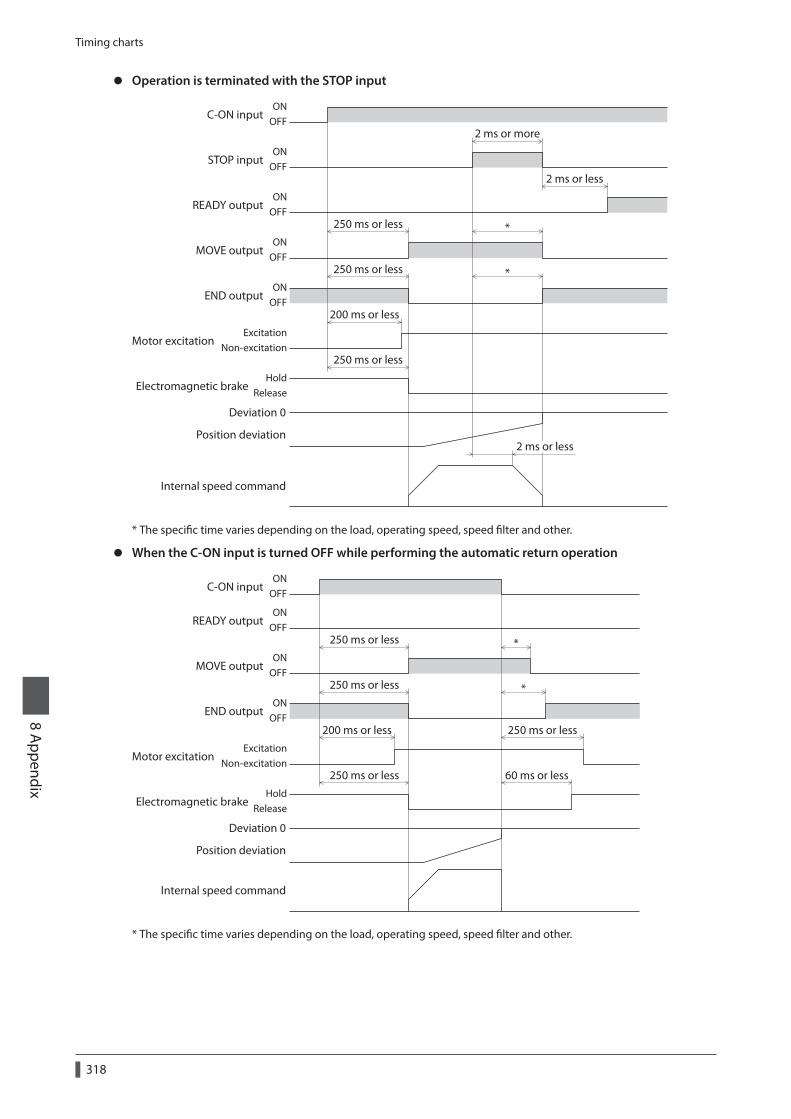
Timing charts
8 Appendix
318
z Operation is terminated with the STOP input
C-ON inputON
OFF
ONOFF
ONOFF
ONOFF
READY output
250 ms or less
250 ms or less
200 ms or less
250 ms or less
MOVE output
ONOFF
STOP input
END output
2 ms or less
2 ms or less
2 ms or more
*
*
ExcitationNon-excitation
Motor excitation
HoldRelease
Electromagnetic brake
Position deviation
Internal speed command
Deviation 0
* The specific time varies depending on the load, operating speed, speed filter and other.
z When the C-ON input is turned OFF while performing the automatic return operation
C-ON inputON
OFF
ONOFF
ONOFF
ONOFF
READY output
250 ms or less
250 ms or less
200 ms or less
250 ms or less
250 ms or less
60 ms or less
MOVE output
END output
ExcitationNon-excitation
Motor excitation
HoldRelease
Electromagnetic brake
*
*
Position deviation
Internal speed command
Deviation 0
* The specific time varies depending on the load, operating speed, speed filter and other.

Specifications8 A
ppendix
319
2 Specifications
Check on the Oriental Motor Website for the product specifications.

General specifications
8 Appendix
320
3 General specifications
3-1 AC power input
Motor Driver
Degree of protection IP65 *1 (IP20 for the double-shaft type) IP10
Operation environment
Ambient temperature
−10 to +50 °C (+14 to +122 °F) *2 (non-freezing)
Harmonic geared type: 0 to +40 °C (+32 to +104 °F) *2 (non-freezing)
0 to +55 °C (+32 to +131 °F) *3 (non-freezing)
Humidity 85% or less (non-condensing)
Altitude Up to 1,000 m (3,300 ft.) above sea level
Surrounding atmosphere
No corrosive gas, dust, water, or oil
Storage environment
Ambient temperature
−20 to +60 °C (−4 to +140 °F) (non-freezing) −25 to +70 °C (−13 to +158 °F) (non-freezing)
Humidity 85% or less (non-condensing)
Altitude Up to 3,000 m (10,000 ft.) above sea level
Surrounding atmosphere
No corrosive gas, dust, water, or oil
Shipping environment
Ambient temperature
−20 to +60 °C (−4 to +140 °F) (non-freezing) −25 to +70 °C (−13 to +158 °F) (non-freezing)
Humidity 85% or less (non-condensing)
Altitude Up to 3,000 m (10,000 ft.) above sea level
Surrounding atmosphere
No corrosive gas, dust, water, or oil
Insulation resistance
100 MΩ or more when 500 VDC megger is applied between the following places:
•Case - Motor and sensor windings
•Case - Electromagnetic brake windings
100 MΩ or more when 500 VDC megger is applied between the following places:
• Protective Earth Terminals - Power supply terminals
• Signal I/O terminals - Power supply terminals
Dielectric strength
Sufficient to withstand 1.5 kVAC at 50/60 Hz applied between the following places for 1 minute:
•Case - Motor and sensor windings
•Case - Electromagnetic brake windings
Sufficient to withstand the following for 1 minute, leak current 13 mA or less.
• Protective Earth Terminals - Power supply terminals 1.8 kVAC 50/60 Hz
• Signal I/O terminals - Power supply terminals 1.9 kVAC 50/60 Hz
*1 Excluding the mounting surface and connectors.*2 When installing a motor to a heat sink of a capacity at least equivalent to an aluminum plate [250×250 mm
(9.84×9.84 in.), thickness 6 mm (0.24 in.)].*3 When installing a driver to a heat sink of a capacity at least equivalent to an aluminum plate [200×200 mm
(7.87×7.87 in.), thickness 2 mm (0.08 in.)].

General specifications8 A
ppendix
321
3-2 DC power input
Motor Driver
Degree of protection
IP65 (Excluding the mounting surface and connectors.) IP20 (Double shaft type, models that the “motor identification” in the product model name is “S”)
IP10
Operation environment
Ambient temperature
−10 to +50 °C (+14 to +122 °F) * (non-freezing)
Harmonic geared type: 0 to +40 °C (+32 to +104 °F) * (non-freezing)
0 to +50 °C (+32 to +122 °F) (non-freezing)
Humidity 85% or less (non-condensing)
Altitude Up to 1,000 m (3,300 ft.) above sea level
Surrounding atmosphere
No corrosive gas, dust, water, or oil
Storage environment
Ambient temperature
−20 to +60 °C (−4 to +140 °F) (non-freezing)
−25 to +70 °C (−13 to +158 °F) (non-freezing)
Humidity 85% or less (non-condensing)
Altitude Up to 3,000 m (10,000 ft.) above sea level
Surrounding atmosphere
No corrosive gas, dust, water, or oil
Shipping environment
Ambient temperature
−20 to +60 °C (−4 to +140 °F) (non-freezing)
−25 to +70 °C (−13 to +158 °F) (non-freezing)
Humidity 85% or less (non-condensing)
Altitude Up to 3,000 m (10,000 ft.) above sea level
Surrounding atmosphere
No corrosive gas, dust, water, or oil
Insulation resistance
100 MΩ or more when 500 VDC megger is applied between the following places:
•Case - Motor and sensor windings
•Case - Electromagnetic brake windings
100 MΩ or more when 500 VDC megger is applied between the following places:
• Frame Ground Terminal - Power supply terminals
Dielectric strength
Sufficient to withstand 1.0 kVAC (0.5 kVAC for ARM14, ARM15, ARM24, and ARM26) at 50/60 Hz applied between the following places for 1 minute:
•Case - Motor and sensor windings
•Case - Electromagnetic brake windings
Sufficient to withstand 500 VAC at 50/60 Hz applied between the following places for 1 minute:
• Frame Ground Terminal - Power supply terminals
* When installing a motor to a heat sink of a capacity at least equivalent to an aluminum plate [100×100 mm (3.94×3.94 in.), thickness 6 mm (0.24 in.)].

Regulations and standards
8 Appendix
322
4 Regulations and standards
4-1 UL Standards
Check the "APPENDIX UL Standards for AR Series" for recognition information about UL Standards.
4-2 EU Directives
CE Marking (AC power input)This product is affixed the CE Marking under the Low Voltage Directive and EMC Directive.
z Low Voltage Directive
Applicable Standards
Motor EN 60034-1, EN 60034-5, EN 60664-1
Driver EN 61800-5-1
Installation conditions
Motor
To be incorporated in equipment Overvoltage category: II Pollution degree: 3 (2 for the double-shaft type) Protection against electric shock: Class I
Driver
To be incorporated in equipment Overvoltage category: II Pollution degree: 2 Protection against electric shock: Class I
• This product cannot be used in IT power distribution systems. • Install the product within the enclosure in order to avoid contact with hands. • Be sure to perform protective grounding if a product can be touched with hands. When installing the motor and
driver, securely connect their Protective Earth Terminals. • To protect against electric shock using an earth leakage breaker (RCD), connect a type B earth leakage breaker to
the primary side of the driver. • When using a circuit breaker (MCCB), use a unit conforming to the EN or IEC standard. • Isolate the motor cable, power-supply cable and other drive cables from the signal cables (CN1, CN4 to CN9) by
means of double insulation. • The temperature of the driver's heat sink may exceed 90 °C (194 °F) depending on the driving conditions.
Accordingly, take heed of the following items: • Do not touch the driver. • Do not use the driver near flammable objects. • Always conduct a trial operation to check the driver temperature.
z EMC DirectivesThis product is conducted EMC testing under the conditions specified in “Example of motor and driver installation and wiring” on p.48. The conformance of your mechanical equipment with the EMC Directive will vary depending on such factors as the configuration, wiring, and layout for other control system devices and electrical parts used with this product. It therefore must be verified through conducting EMC measures in a state where all parts including this product have been installed in the equipment.
Applicable Standards
EMI EN 55011 group 1 class A, EN 61000-6-4, EN 61800-3
EMS EN 61000-6-2, EN 61800-3
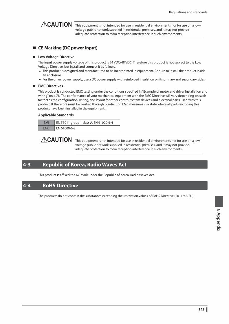
Regulations and standards8 A
ppendix
323
This equipment is not intended for use in residential environments nor for use on a low-voltage public network supplied in residential premises, and it may not provide adequate protection to radio reception interference in such environments.
CE Marking (DC power input)
z Low Voltage DirectiveThe input power supply voltage of this product is 24 VDC/48 VDC. Therefore this product is not subject to the Low Voltage Directive, but install and connect it as follows.
• This product is designed and manufactured to be incorporated in equipment. Be sure to install the product inside an enclosure.
• For the driver power supply, use a DC power supply with reinforced insulation on its primary and secondary sides.
z EMC DirectivesThis product is conducted EMC testing under the conditions specified in “Example of motor and driver installation and wiring” on p.78. The conformance of your mechanical equipment with the EMC Directive will vary depending on such factors as the configuration, wiring, and layout for other control system devices and electrical parts used with this product. It therefore must be verified through conducting EMC measures in a state where all parts including this product have been installed in the equipment.
Applicable Standards
EMI EN 55011 group 1 class A, EN 61000-6-4
EMS EN 61000-6-2
This equipment is not intended for use in residential environments nor for use on a low-voltage public network supplied in residential premises, and it may not provide adequate protection to radio reception interference in such environments.
4-3 Republic of Korea, Radio Waves Act
This product is affixed the KC Mark under the Republic of Korea, Radio Waves Act.
4-4 RoHS Directive
The products do not contain the substances exceeding the restriction values of RoHS Directive (2011/65/EU).

8 Appendix
324

325
Revision record
Revision number Revised contents
First edition
Second edition • Revision of words and terms
•Correction of minor erroneous descriptions
Third edition
•Addition of descriptions about adding models
•Addition of cable set models in accessories
•Correction of minor erroneous descriptions

• Unauthorized reproduction or copying of all or part of this Manual is prohibited. If a new copy is required to replace an original manual that has been damaged or lost, please contact your nearest Oriental Motor sales office.
• Oriental Motor shall not be liable whatsoever for any problems relating to industrial property rights arising from use of any information, circuit, equipment or device provided or referenced in this manual.
• Characteristics, specifications, and dimensions are subject to change without notice. • While we make every effort to offer accurate information in the manual, we welcome your input. Should you find unclear
descriptions, errors or omissions, please contact your nearest Oriental Motor sales office. • , , and are registered trademarks or trademarks of Oriental Motor Co., Ltd., in Japan and other
countries. Modbus is a registered trademark of the Schneider Automation Inc. CC-Link is a registered trademark of the CC-Link Partner Association. EtherCAT® is registered trademark and patented technology, licensed by Beckhoff Automation GmbH, Germany. MECHATROLINK is a registered trademark of the MECHATROLINK Members Association. Other product names and company names mentioned in this manual may be registered trademarks or trademarks of their respective companies and are hereby acknowledged. The third-party products mentioned in this manual are recommended products, and references to their names shall not be construed as any form of performance guarantee. Oriental Motor is not liable whatsoever for the performance of these third-party products.
© Copyright ORIENTAL MOTOR CO., LTD. 2017Published in November 2018
• Please contact your nearest Oriental Motor oce for further information.
Technical Support Tel:(800)468-39828:30 A.M. to 5:00 P.M., P.S.T. (M-F)7:30 A.M. to 5:00 P.M., C.S.T. (M-F)www.orientalmotor.com
Schiessstraße 44, 40549 Düsseldorf, GermanyTechnical Support Tel:00 800/22 55 66 22www.orientalmotor.de
Tel:01256-347090www.oriental-motor.co.uk
Tel:01 47 86 97 50www.orientalmotor.fr
Tel:02-93906346www.orientalmotor.it
Tel:0800-060708www.orientalmotor.com.tw
SingaporeTel:1800-8420280www.orientalmotor.com.sg
Tel:1800-806161www.orientalmotor.com.my
KoreaTel:080-777-2042www.inaom.co.kr
4-8-1 Higashiueno, Taito-ku, Tokyo 110-8536 JapanTel:03-6744-0361www.orientalmotor.co.jp
Tel:1800-888-881www.orientalmotor.co.th
Tel:400-820-6516www.orientalmotor.com.cn
Tel:+55-11-3266-6018www.orientalmotor.com.br
Tel:+91-80-41125586www.orientalmotor.co.in
Hong Kong BranchTel:+852-2427-9800