stereo ground segment, science operations, and data...
TRANSCRIPT

Space Sci RevDOI 10.1007/s11214-007-9249-4
STEREO Ground Segment, Science Operations, andData Archive
J. Eichstedt · W.T. Thompson · O.C. St. Cyr
Received: 6 October 2006 / Accepted: 19 July 2007© Springer Science+Business Media B.V. 2007
Abstract Vitally important to the success of any mission is the ground support systemused for commanding the spacecraft, receiving the telemetry, and processing the results.We describe the ground system used for the STEREO mission, consisting of the MissionOperations Center, the individual Payload Operations Centers for each instrument, and theSTEREO Science Center, together with mission support from the Flight Dynamics Facil-ity, Deep Space Mission System, and the Space Environment Center. The mission planningprocess is described, as is the data flow from spacecraft telemetry to processed science datato long-term archive. We describe the online resources that researchers will be able to useto access STEREO planning resources, science data, and analysis software. The STEREOJoint Observations Program system is described, with instructions on how observers can par-ticipate. Finally, we describe the near-real-time processing of the “space weather beacon”telemetry, which is a low telemetry rate quicklook product available close to 24 hours a day,with the intended use of space weather forecasting.
Keywords STEREO · Space weather · Science operations · Data archive · Solarobservations
1 Introduction
The STEREO ground system provides the means for planning the STEREO mission, com-municating the plans to the STEREO observatories, assessing and maintaining the health andsafety of the observatories, and providing detailed data products from these processes to the
J. EichstedtApplied Physics Laboratory, Johns Hopkins University, Laurel, MD 20723, USA
W.T. Thompson (�)Adnet Systems Inc., NASA Goddard Space Flight Center, Code 671, Greenbelt, MD 20771, USAe-mail: [email protected]
O.C. St. CyrNASA Goddard Space Flight Center, Greenbelt, MD, USA

J. Eichstedt et al.
Fig. 1 STEREO ground segment teams and interfaces
STEREO community. Of primary interest to the community are the science data collected,which are brought down from the observatories daily and ultimately reside at the STEREOScience Center for retrieval by the international science community and the general public.
The STEREO ground system consists of several operations centers which each play arole in the STEREO science mission. These operations centers are distributed across theworld and consist of the Mission Operations Center (MOC), four Payload Operations Cen-ters (POCs), the STEREO Science Center (SSC), the Flight Dynamics Facility (FDF), andthe Deep Space Mission System (DSMS) which operates the Deep Space Network (DSN).The STEREO ground segment provides the means for these operations centers to performtheir individual tasks as well as to communicate necessary data products between centers andthe observatories. Figure 1 depicts the STEREO ground segment teams and interfaces. TheSTEREO Mission Operations Center is located at the Johns Hopkins University/AppliedPhysics Laboratory in Laurel, MD, and is the center that operates the observatory bus andserves as the collection and distribution point for the instrument commands and telemetry.The Payload Operation Centers are the instrument operations centers that generate the com-mands for each of the four STEREO instrument suites and monitor instrument health andsafety. These centers are located at the Naval Research Laboratory in Washington, DC; theUniversity of California–Berkeley in Berkeley, CA; the University of Minnesota in Min-neapolis, MN; and the University of New Hampshire in Durham, NH. These are the homebases for the instrument POCs, but they are able to operate remotely when necessary andalso maintain a presence at the MOC. The SSC, located at the Goddard Space Flight Centerin Greenbelt, MD, provides science coordination and serves as the STEREO archive. Alsolocated at GSFC is the FDF, which performs STEREO navigation services. The DSMS isoperated by the Jet Propulsion Laboratory in Pasadena, CA, with ground stations in Califor-nia, Madrid, Spain, and Canberra, Australia.

STEREO Ground Segment, Science Operations, and Data Archive
1.1 Mission Requirements and the Ground System Design
The top-level requirements levied on the STEREO ground system which influenced theground system design can be broken down into four major components:
• All instrument operations will be decoupled from the spacecraft bus operations. The in-struments and the spacecraft bus will be operated almost entirely independent of eachother. The same can be said about the ground elements (the POCs and the MOC).
• The ground system will support subsystem development, observatory integration, andmission operations.
• The spacecraft and ground system will be designed to deliver an average of 5 Gbits ofscience data per day per observatory to the instrument POCs and the SSC.
• The MOC will provide the data products to the SSC and instrument Payload OperationsCenters (POCs). These data products consist of Level 0 telemetry data and Mission Sup-port Data.
Decoupled instrument operations has the effect of greatly simplifying mission operationsand the ground planning tools. The STEREO mission is ideal for implementing this sepa-ration of spacecraft and instrument operations as there are essentially no shared resources.The spacecraft continually points at the Sun and therefore no coordination is required forencounters and enough power is available to support all instrument operations at all times.In addition, the SSR is portioned such that each instrument (or instrument suite) has its ownpartitions for recording science data and each POC is responsible for managing its parti-tions. There are some events that require spacecraft and instrument coordination, such ascalibration maneuvers and software loads, but these are coordinated individually and occurinfrequently.
The STEREO ground system has evolved over time to support the mission as it is devel-oped. The early system consists of “mini-MOCs”, which are single workstations that supportsubsystem development. Each mini-MOC contains the same command and control systemwhich is built up into the I&T MOC and the MOC. The mini-MOC contains its own archivewithin the workstation, while the I&T and Flight MOC is more distributed with an archiveand tools specific to I&T and Mission Operations. This concept has been used at APL formany past missions and simplifies spacecraft and operations development.
The data return requirement of 5 Gbits per day on average primarily determines theduration of the DSN tracks and hence is the largest factor in the DSN scheduling process.Throughout the STEREO mission, the track durations are increased as the supported datarates are reduced. The daily track times planned for STEREO take into account data frompast deep space missions such as the number of missed tracks, delayed acquisitions, andsafe mode demotions. Enough additional track time has been scheduled and the SSR islarge enough to support daily downlink of “extra” data such that the yearly daily averageshould be realized.
There are many data products produced by the STEREO MOC which fulfill the require-ments and desires of the mission and instrument teams. These products are produced throughthe planning, control, and assessment processes and are distributed through an ftp server inthe STEREO MOC.
1.2 Spacecraft and Mission Operations
1.2.1 STEREO Spacecraft
Each of the two STEREO spacecraft are nearly identical with selective redundancy. Thespacecraft bus was built by JHU/APL with NASA Goddard Space Flight Center (GSFC)

J. Eichstedt et al.
procuring the instruments. The entire spacecraft was integrated at JHU/APL. The spacecraftdesign is described more fully in Driesman and Hynes (2007), but a short summary is givenhere to lead into the discussion of operations.
The spacecraft bus consists of six operational subsystems supporting a payload suite offour instruments. The spacecraft bus is designed around an Integrated Electronics Module(IEM). The IEM is a single box that contains the Command & Data Handling (C&DH),Guidance and Control (G&C), and Solid State Recorder (SSR) on plug-in cards. A MIL-STD-1553 bus architecture is used for command and telemetry between the IEM and the in-strument Data Processing Units (DPU), Guidance and Control (G&C) processor, Transpon-der, Star Tracker, Inertial Measurement Unit (IMU), and Power subsystem.
The C&DH subsystem provides real-time, timetagged, macro, and autonomy commandcapabilities. It uses a Rad 6000, 25 MHz, 32-bit processor that formats all spacecraft bustelemetry into CCSDS compliant packets. An 8.5 Gbit RAM Solid State Recorder (SSR)is used for data storage of all science and engineering data. An Oven Controlled CrystalOscillator (OCXO) is used for time reference.
The RF Communications subsystem provides simultaneous X-Band (XB) uplink, down-link, and navigation data using one High Gain Antenna (HGA) and two Low Gain Antennas(LGA). The LGAs provide communications from launch through the phasing orbits and isused for emergency communications when the spacecraft is in Earth Acquisition mode. TheHGA consists of a gimbaled, 1.2 meter, parabolic dish with a 180-degree gimbal travel. Itwill be used when the spacecraft range is greater than 0.2 AU. There are five XB uplink rates,125, 500, 1,000, and 2,000 bps for normal operations and 7.8125 bps for emergency oper-ations. The RF Communications subsystem is designed to use the DSMS 34-meter BeamWave Guide (BWG) antennas, although any 34 m or 70 m antenna with XB uplink anddownlink can be used.
The G&C subsystem provides three-axis attitude control of the spacecraft and also con-trols the pointing of the HGA. Nominal orientation of the spacecraft will have the +X-axisof the spacecraft pointed at the Sun within 0.1° and the HGA, near the Z-axis, will bepointed at the Earth within ±0.35°. The G&C subsystem consists of one Rad 6000 proces-sor, the Attitude Interface Electronics (AIE)/1553 Board, three attitude sensors, an InertialMeasurement Unit (IMU), Star Tracker, and Digital Solar Attitude Detectors (DSAD), andtwo control actuators, Reaction Wheel Assemblies (RWA) and the Propulsion subsystem.
The AIE/1553 Board provides the 1553 digital interface between the analog G&C com-ponents, i.e., DSADs, RWA, HGA gimbal, and thrusters, and the C&DH subsystem. It con-sists of an electronics board in the Power Distribution Unit (PDU).
During a serious spacecraft emergency (processor reboot, hardware Low Voltage Sense(LVS), or command loss timeout) the spacecraft will go through a system reset and enterEarth Acquisition (EA) mode. Both processors will reboot and the C&DH/EA processorwill come up using the EA application. The EA application combines the functionality ofthe C&DH application along with basic G&C functionality, i.e., using measured data only itwill maintain attitude control (inertial knowledge will not be known). The G&C processorwill reboot and reload the G&C application; however, it will essentially be idling since itwill not be receiving G&C sensor data nor have control over the G&C actuators. The EAapplication will point the +X axis of the spacecraft at the Sun, switch to the summed LGAs,reduce the downlink and uplink rates to a minimum, and go into a 5°/min roll about the X-axis.
The IMU (redundant) provides spacecraft rate and acceleration data using Ring LaserGyros and accelerometers. The Star Tracker can autonomously identify up to nine stars,

STEREO Ground Segment, Science Operations, and Data Archive
using a 16.4° × 16.4° field of view (FOV), with brightness between +0.1 to +5.5 magni-tude. There are five DSADs each with a ±64° FOV to determine the Sun location with anaccuracy of 0.5°.
Four RWA provide pointing control. As system momentum builds in the RWAs, it willbe dumped, approximately every 13 days, using the thrusters in the Propulsion subsystem.While the G&C can autonomously perform momentum dumps, they are expected to beplanned and controlled by mission operations so as to avoid any interference with sciencedata collection.
The Propulsion subsystem consists of two hydrazine propellant tanks, one transducer,three high-pressure latch valves, and 12 4.5 N m thrusters. There will be sufficient propellantto dump momentum for five years with a 10% leakage allowance.
The Power subsystem employs two fixed GaAs/Ge solar arrays (SA). Power is managedby a Peak Power Tracker (PPT) to provide an unregulated 22 to 35 V DC bus. A 23 ampere-hour NiH2 battery provides power from launch to SA deployment and for Low VoltageSense (LVS) conditions.
The Thermal subsystem is a passive design using blankets, radiators, and thermostaticallycontrolled heaters. All instruments are thermally isolated from the spacecraft structure
1.2.2 STEREO Mission Operations
The STEREO mission consists of continually pointing at the Sun as the observatories moveaway from the Earth at 22 deg/year while remaining approximately the same distance fromthe Sun throughout the mission. In this orbit, the solar array input power is sufficient tocover any instrument mode and the observatory remains thermally stable. Each instrumenthas its own partitions to use on the SSR which are typically set by Mission Operations to anoverwrite mode. This leaves the spacecraft and instruments with no power, thermal, or SSRconstraints other than managing the amount of data being placed in their SSR partitions.However, there are a two resources that are shared between the instruments which must bemanaged. These are the downlink during the phasing orbits, and the Stored Command Buffer(SCB) in the C&DH. The SCB is 20 kbits in size and must be managed so as not to overloadit. This space is primarily used by the SWAVES instrument, but is also available to PLASTICand IMPACT. The SSC will be managing these two resources by negotiating between theinstruments for the available downlink during early operations and by coordinating the useof the SCB during the mission.
Telemetry is received from the observatory by the DSN during daily tracks. During mostof the track, the SSR is played back and collected by the DSN Central Data Recorder whilethe real-time telemetry is flowed directly to the MOC. These real-time data are made avail-able to the POCs through a socket connection to the MOC. The real-time data can also be“played back” from the MOC archive via a socket connection. The Central Data Recorderwill ftp the full data set from the track (both real-time and SSR playback) in 30-minute files.Once all these files are collected by the MOC, they will be processed into level 0 data foreach instrument and the SSC and be made available to the instrument POCs and the SSCwithin 24 hours after receipt of all the data from the DSN via ftp from the STEREO DataServer in the MOC.
Also during each track, commands will be uplinked to the spacecraft beginning early inthe track. Following the upload of spacecraft commands, instrument command queues willbe opened and commands that have been forwarded to the MOC in advance will be uplinkedin a round-robin fashion for each POC. Following this command uplink, the POC commandqueues may be opened to allow real-time commanding by the instrument POCs.

J. Eichstedt et al.
The POCs will maintain the health and safety of their instruments from review of thetelemetry data received and commanding in the process just described. In addition to this,autonomy is onboard the observatory which can power off the instruments at their requestor when the spacecraft requires for health and safety purposes.
1.3 Telemetry and Data Processing
Figure 2 illustrates conceptual flow of command and telemetry data between the ground-based observatory bus and instrument operations elements and the on-orbit STEREO space-craft. The “outer-loop” depicts instrument operations. Using a decoupled instrument opera-tions approach, all instruments will be operated by the instrument operations teams at theirhome POC. In Fig. 2, begin at the POC Planning, on the far right, where instrument com-mands are produced. The command messages, which will be packetized along with someadditional information needed by the MOC, are transmitted to the MOC via the Internet. Atthe MOC (MOC Authorize and Route) there is some checking performed, then these com-mands are queued for eventual uplink to the instrument. Along with the command packets,the POCs will append timing information that indicates the time span (earliest and latesttimes) over which the command packet may be uplinked to the spacecraft instrument. Real-time command packets, when uplinked to the spacecraft, are immediately routed by thespacecraft bus to the appropriate instrument and time tagged command packets are storedin the instrument’s stored command buffer in the observatory bus Command and Data Han-dling (C&DH) system. Conceptually, the command packet goes “directly” from the POCto the instrument, since the MOC, ground station and spacecraft bus are merely the deliv-ery system. This delivery system notifies the POC of the delivery status of the commandmessage.
Whereas the POCs produce instrument commands, the MOC produces spacecraft buscommands. This is depicted in the “inner-loop” on the data flow diagram (Fig. 2). Startingat the MOC Planning process, the Mission Operations Team (MOT) prepares commandmessages to the spacecraft bus to operate it during the next day. These command messagesare queued for uplink (MOC Authorize and Route) just like the instrument commands, onlythey go to a different destination (via the C&DH Routing Service). Real-time commands areimmediately routed, by the C&DH processor, to the appropriate spacecraft subsystem andtimetagged and macro commands are stored in the C&DH processor. The MOC receivesdelivery status of the command packets just as the POCs do.
The onboard instruments produce science and engineering data (Instrument Data Collec-tion) in response to the uplinked command messages. The data produced by the instrumentsare sent to the spacecraft data system in the form of CCSDS telemetry packets. Similarly, en-gineering data produced by the spacecraft bus are also formatted into CCSDS packets. Thesepackets produced by the instruments and the spacecraft bus and conveyed to the spacecraftdata system (C&DH Combine) are stored on the Solid State Recorder (SSR) within thespacecraft data system (C&DH Recording). During a ground track with the spacecraft, thecontents of the SSR are transmitted to the MOC (C&DH Frame Packaging).
On the ground (Ground System Telemetry Routing), real-time data are forwarded to theMOC and POCs, while all recorded data are sent to the STEREO Data Server (SDS). Allinstrument data will be processed into level 0 data files and sent to the POCs for furtherprocessing and analysis, and to the STEREO Science Center for mission archival. The cyclerepeats, with the POCs preparing instrument commands for still another day in space. Space-craft bus data are routed to the MOC (MOC Assessment) where an assessment function isperformed. The MOC spacecraft bus planning process then repeats.

STEREO Ground Segment, Science Operations, and Data Archive
Fig
.2D
ecou
pled
inst
rum
ento
pera
tions
data
flow

J. Eichstedt et al.
2 STEREO Mission Operations Center
The MOC has the primary responsibility of management of the spacecraft bus including thedevelopment of command messages and the uplink to the spacecraft by way of the DSN. Re-covery of spacecraft bus engineering (state-of-health) telemetry and the performance analy-sis based on this telemetry is also performed at the MOC. The MOC receives instrumentcommand messages from the POCs and, after verification that the command ApIDs are ap-propriate for the POC they came from, queues these for uplink to the spacecraft based onstart and expiration times appended to the command messages by the POC. The MOC doesnot directly verify any instrument commands and does not decommutate or analyze any in-strument telemetry aside from currents and temperatures observed from the spacecraft sideof the instruments. Each POC is individually responsible for the health and safety of itsinstrument. The MOC does control the instrument power service and can power off an in-strument at the request of the POC. In addition, an instrument can autonomously request tobe powered down through the spacecraft fault protection system.
2.1 Local Area Network Architecture
Figure 3 illustrates the MOC and the supporting network architecture including interfacesto other mission operations elements. Restricted IONet communication lines connect theMOC primary and backup command workstations to the DSN through a firewall. PCs run-ning Memory Allocation Examiner (MAX) are the only other computers on the Prime Re-stricted IONet network. These workstations are connected to the Ops “Demilitarized Zone”(DMZ) network through another firewall. The Ops DMZ network houses the assessmentworkstations and a series of X-Terminals which can display real-time and playback teleme-try data to the spacecraft engineering team within the MOC. The Ops DMZ also contains theSTEREO Planning system software, real-time telemetry servers, the POC command accep-tor, the STEREO Data Server, the second-level archive which stores decommutated space-craft telemetry for trending, and the Spacecraft Hardware in the Loop Simulators. The OpsDMZ Network is in turn connected to the Internet via a third firewall. The SSC, POCs, andthe FDF connect to the Ops DMZ via the Internet to retrieve STEREO Data Products fromthe SDS and to deliver instrument commands via the POC Command Acceptor. Should theInternet be inaccessible to the POCs or SSC, the Ops DMZ can be accessed through a mo-dem pool. Two additional STEREO workstations will be housed in the APL Multi-MissionMOC which is an Operations facility located in a different building within the APL campus.These workstations are for emergency state-of-health command and telemetry and would beused should a disaster consume the STEREO MOC. These machines are maintained withcurrent files and software for this purpose.
2.1.1 STEREO Telemetry Flow
Real-time telemetry from each STEREO spacecraft will flow from the spacecraft into theDSN and be routed through the Restricted IONet to APL on a low-latency delivery pathwith complete data delivery not guaranteed. These data are flowed to the Ops DMZ networkwhere they can be viewed in real-time by the spacecraft engineering team or the POCs eitherlocally or remotely. The data are stored for several days on the data servers where they can beplayed back via instant replay in the MOC or across the Internet at the request of the POCs.The SSR playback data are recorded at the Central Data Recorder (CDR) at JPL where theyare sent to the MOC in half-hour segment Intermediate Data Record (IDR) files over the

STEREO Ground Segment, Science Operations, and Data Archive
Fig
.3M
OC
netw
ork
arch
itect
ure

J. Eichstedt et al.
Internet. These data are guaranteed complete and are the data that will be used to populatethe raw archive and generate level 0 data. Daily, and upon complete playback of the SSR andMOC receipt of all the IDR files from the CDR, level 0 data are processed for each of theinstrument POCs and the spacecraft housekeeping data. Level 0 data are time ordered withduplicates removed. Each day level 0 files are produced for the previous day, the precedingday, the day before that, and for 30 days earlier. This allows for the delivery of data that mayhave resided on the SSR for a few days and it is expected that the file from 30 days ago willbe the final delivery with the complete data for that day. Due to the volume of data in theSECCHI POC partitions, each of these level 0 files are produced in 4-hour segments whereall the other level 0 files are produced for a 24-hour period. Once generated, the level 0 filesare placed on the STEREO Data Server (within 24 hours from receipt of the IDR files fromthe DSN) where they can be retrieved by the POCs and SSC. These files are maintained onthe SDS for 30 days when they can be removed after receipt of the Archive Products Listfrom the SSC indicating that they have retrieved the data.
2.1.2 STEREO Command Flow
The IMPACT, PLASTIC, SECCHI, and SWAVES POCs will send to the MOC CommandMessages that contain the information needed to configure and control their instruments.These command messages will be sent to the MOC at least eight hours prior to the start ofthe track that they are scheduled for uplink. The MOC shall authenticate and perform min-imal syntax checks on the command messages, and sends an Authorization Return Receiptmessage back to the POCs facility indicating the message status. If the POCs want to deletepreviously transmitted command messages prior to their upload, the POC verbally sends theMOC a command flush request. Based on the command delivery time information includedin the command message header, the MOC shall forward the validated queued commandmessages to the Deep Space Mission System (DSMS) interface for transfer to the space-craft in a round-robin format between the POCs. Finally, the Command and Data Handling(C&DH) process on the spacecraft shall forward the commands to the 1553 bus for instru-ment retrieval. Actual command execution success or failure will be indicated in instrumenttelemetry telltales. In addition to verification of instrument commands through instrumenttelemetry, the As Run Track Plan and the Command and Packet History data products aresent out to assist in tracking instrument commands.
During instrument commissioning, instrument special events such as software loads, andduring instrument emergencies, real-time commanding by the instrument POC is also avail-able. In this case, the commands flow directly from the POC, through the POC CommandAcceptor in the MOC where they are transferred to the Restricted IONet and flowed di-rectly to the DSMS and up to the spacecraft. The MOC can control which POCs will becommanding in real-time and during emergencies, instrument commissioning, and softwareloads, will restrict realtime commanding to a single POC.
Within the C&DH subsystem on the spacecraft there is also an Instrument Stored Com-mand Buffer. The SWAVES, IMPACT, and PLASTIC POCs may use this Stored CommandBuffer to load time tagged commands for their respective instruments. This 20 k buffer willstore instrument packets until the UTC time associated with the command packet when itwill then forward it to the instrument. The POCs and SSC manage this buffer such that itis not overfilled and following each track the MOC will produce a Stored Command Bufferreport indicating the command packets within the buffer to assist in managing it. The StoredCommand Buffer on the spacecraft can also be flushed of instrument commands by theMOC, at the request of each POC.

STEREO Ground Segment, Science Operations, and Data Archive
2.2 MOC Personnel
The STEREO Mission Operations Team at APL will launch with 14 team members. This14-member team will be reduced to 12 by the end of the phasing orbits. The launch teamorganization consists of:
1 Mission Operations Manager4 Real-time controllers8 Spacecraft Specialists1 Anomaly Officer.
Following the phasing orbits the team will operate without the Anomaly Officer andwith the Mission Operations Manager also serving as a Spacecraft Specialist. At launch +6months the team will transition to unattended tracks and will reduce to eight Spacecraft Spe-cialists. At Heliocentric Orbit +1 year the team is expected to reduce again to six SpacecraftSpecialists for the remainder of the mission.
Each of the above positions will have the following responsibilities:
• Mission Operations Manager (MOM): The Mission Operations Manager will be respon-sible for verifying the readiness of the ground system for launch. The MOM will also bethe primary maneuver planner during the phasing orbits, prepare the weekly status reportfor the MOC, and serve on the post launch Configuration Control Board. Following com-pletion of all spacecraft maneuvers, the MOM will also serve as one of the SpacecraftSpecialists.
• Real-Time Controller: The real-time controllers will be the primary interface with theDSN for each real-time track. They will configure the ground system, verify readiness foreach track with the DSN Station, and handle ground system contingencies.
• Spacecraft Specialist: The Spacecraft Specialists will serve as the Planners, real-timespacecraft evaluators during DSN tracks, and perform spacecraft assessment. The Space-craft Specialist team will rotate through these roles on a weekly basis.
• Anomaly Officer: The Anomaly Officer is unique to early operations. This role will con-sist of organizing the larger team (Mission Operations and Spacecraft Engineers) to solveanomalies early after launch. The Anomaly Officer will be intimately familiar with theContingency Handbook and will be able to effectively lead the team in resolving anom-alies.
2.3 Other Ground Segment Elements
2.3.1 Deep Space Mission System
The Deep Space Mission System (DSMS) will be used to provide communications to bothspacecraft from launch to end of life (EOL). The use of all three DSMS antenna facilities,Goldstone, Madrid, and Canberra, are required to determine the elevation component for thenavigation of each spacecraft. Nominally, one 3.5- to 5-hour track, depending on spacecraftrange, centered every 24 hours per spacecraft will be conducted using the 34-meter BWGsubnet.
The MOC is connected to the DSMS via Restricted IONet links. Commands will beflowed to the DSN using the standard Space Link Extension Service over the RestrictedIONet and real-time telemetry will be flowed from the DSN to the MOC over the RestrictedIONet using legacy UDP service. Playback data received at the DSN station will be flowed tothe Central Data Recorder at JPL where they will in turn be flowed in half-hour increments

J. Eichstedt et al.
to the MOC via FTP as IDR files. Orbit data for each spacecraft will be provided to DSMSfrom the FDF for acquisition and ranging data will be distributed from the DSMS to theFDF for orbit determination purposes over the Restricted IONet.
2.3.2 Flight Dynamics Facility
The Flight Dynamics Facility (FDF) at Goddard Space Flight Center determines the orbitsof the observatory from tracking data provided by the DSN ground stations, and generatespredicted DSN station contact periods and predicted and definitive orbit data products. TheFDF also generates orbital ephemeris data in support of orbit maneuvers that satisfy scienceand mission requirements and transfers this information to the STEREO MOC via the FDFProducts Center.
Locally, Delta launch and ascent support will be provided by the FDF ExpendableLaunch Vehicle (ELV) Support Team, whose role it is to provide the following: (1) launchvehicle acquisition data delivered to tracking sites supporting the ascent, and (2) an orbitalinsertion state vector based on Delta internal guidance telemetry. The orbital insertion statevector obtained in this way provides the first indication of the status of the achieved orbit.The orbital insertion state vector will be delivered by the ELV team to the FDF STEREO or-bit determination team and to the APL Mission Design Team for evaluation. At the FDF, theinsertion vector may also be used to update tracker acquisition data and to become a “seed”vector for the orbit determination process. Once the two spacecraft have been acquired bytwo DSN stations, tracking data for each will begin to flow to the FDF. The FDF will per-form orbit determination operations on a daily basis, obtaining and delivering to APL a statevector solution at least once per day. Ephemeris files based on these solutions will also begenerated and delivered to APL and JPL.
The FDF will continue collecting tracking data during all tracking passes in the earlyorbit phase, and Orbit Determination (OD) solutions will be updated at intervals followingsufficiently extended orbital solution arcs. However, after the first 24 hours these updatesare expected to occur at least once daily leading up to the first apogee (A1). OD updates willbe computed daily starting seven days in advance of maneuvers to support timely maneuverplanning at APL. For all maneuvers, OD updates will be obtained with an epoch just priorto maneuver ignition and again at an epoch just after maneuver burnout. These OD updateswill support maneuver reconstruction and calibration activities by the APL Mission DesignTeam. The FDF will also support maneuvers by measuring the observed component of delta-V along the station line-of-sight to the spacecraft, where applicable. This radial delta-Vobservation will be communicated to the APL Mission Design Team for use in maneuvercalibration activities.
The phase of the mission between the first apogee of the phasing loops and the lunarswingbys will continue to be operationally intense. The FDF will continue collecting track-ing data according to the daily support schedule. By definition, this phase of the missionextends to two weeks after the lunar swingbys that propel the spacecraft into heliocentricorbit. The FDF OD team will expect the possibility of orbit maneuvers around the time ofevery perigee and apogee. For STEREO-A, there is also a likelihood of a trim maneuver(s)following the first lunar swingby to re-target the second swingby. The APL Mission DesignTeam will keep the FDF apprised of updates to the mission timeline and provide predictedburn details as needed. The FDF will in turn model maneuvers into ephemeris files in caseswhere the span includes maneuver epochs.
During heliocentric orbit, the mission will settle into a routine phase starting immediatelyafter the lunar swingbys, with no more orbit maneuvers expected for the duration of the

STEREO Ground Segment, Science Operations, and Data Archive
mission. The tracking schedule changes as the observatories move further from the Earthwith increased contact time as the data rates are lowered. The FDF will continue to collectthe DSN tracking data on this schedule and will evaluate the tracking data as necessary.
2.3.3 NOAA
During the periods that the STEREO observatories are not in DSN contact, each will bebroadcasting a low-rate “space weather beacon” telemetry stream. The National Oceano-graphic and Atmospheric Administration Space Environment Center (NOAA/SEC) hastaken on the responsibility of coordinating ground stations at various locations around theworld to collect this telemetry and transmit it to the SSC. This process is described in moredetail in Sect. 5.3.
3 STEREO Science Center
The STEREO Science Center (SSC)—located at the NASA Goddard Space Flight Center inGreenbelt, MD—serves four main functions for the STEREO mission. First, it is the primearchive of STEREO telemetry and data, and serves that data to the international sciencecommunity and to the general public, both through its own Web site, and through inter-action with virtual observatories (see Sect. 5.5.1). It is also the collection site, processingcenter, and distribution point for STEREO space weather beacon data. Science coordina-tion between the STEREO instruments, and between STEREO and other observatories, isperformed through the SSC. Finally, the SSC is the focal point for education and publicoutreach activities.
The heritage of the SSC arises from experience acquired in operating earlier solarphysics payloads: NASA’s Solar Maximum Mission (SMM) (Bohlin et al. 1980), and theNASA/ESA Solar and Heliospheric Observatory (SOHO) (St. Cyr et al. 1995). In partic-ular, we are building on the experience of the Solar Data Analysis Center (SDAC), whichgrew out of the earlier SMM Data Analysis Center to support many other missions, includ-ing SOHO.
The task of the SSC is not exactly the same as that of the SMM or SOHO ExperimentOperations Facilities (EOF). In many ways, it’s much simpler, because the SSC has no directrole in instrument commanding. However, the other major roles of the SOHO EOF—sciencecoordination, data archiving, and public outreach—are duplicated in the SSC. In addition,the SSC has the completely new responsibility of collecting and processing space weatherbeacon data, as discussed in Sect. 5.3.
3.1 Local Area Network Architecture
A major design objective of the SSC was to build as much as possible on existing facilitieswithin the NASA GSFC Solar Physics Laboratory. Not only does this result in a considerablecost savings, but it also gives us a major leap forward in expertise to draw on. The primarySTEREO archive will be co-located with the Solar Data Analysis Center (SDAC) whichcurrently serves the SOHO archive, among others.
The STEREO archive will be stored on a series of external RAID storage systems, con-nected to servers through high-speed fiber optic switches. RAID systems provide high levelsof reliability and data integrity. The use of a fiber optic switch allows several servers to allshare the same data archive. Other servers will also be able to access the data through the

J. Eichstedt et al.
network, using one of the fiber-connected nodes as an NFS server. Tasks will be split be-tween servers for load balancing and reliability. There will also be sufficient redundancy incase one or more of the servers fails. The servers will be essentially interchangeable, so thattasks can be easily redistributed to better optimize the system.
A secondary archive will be maintained in a separate building at Goddard, where theSolar Physics Laboratory is housed. This separate (and potentially smaller) archive willprovide several functions. First, it will ease access to the data for SSC personnel and othersin the Solar Physics Laboratory. Second, it will provide some redundancy in case the primaryarchive becomes unavailable. Finally, it allows Web traffic to be split up. Under nominalconditions, general information about the mission will be served from the secondary archive,while data access will be from the primary archive. The primary and secondary archives willbe on completely separate networks, so one of the two archives will still be available even ifthe entire other network is down.
STEREO news releases, and other public affairs materials, will be served from a separateNASA-wide portal site, which will further split Web traffic. When Web traffic increases dueto high-profile news stories, very little of that traffic should impact the primary archive Webserver.
Data on the primary archive site will be backed up internally within the SDAC, and alsodelivered on a regular basis to the NASA National Space Science Data Center (NSSDC) fordisaster recovery and final archive. Data on the secondary archive will be mirrored from theprimary archive, and not backed up independently. Frequent backups will be made of allWeb pages and software directories on both the prime and secondary server.
3.2 SSC Personnel
The STEREO Science Center is under the direct management of the STEREO Project Scien-tist and Deputy Project Scientist. Day-to-day operations are managed by a Chief Observer,who is primarily responsible for the science coordination aspect of the mission, and alsooversees all the other SSC activities. Hardware and operating system maintenance is pro-vided by a System Administrator, while two Senior Programmers provide general softwaredevelopment and maintenance. A Data Scientist assists the international science commu-nity to use the data from the mission, and assists with the science coordination. Scienceanalysis and science planning activities will also be assisted by post-doctoral scientist dur-ing mission operations. Education and public outreach activities are assisted by a Web De-signer/Graphics Artist, and a Media Specialist.
Many of the technical positions will be shared with the SDAC, while the education andoutreach personnel will be shared with SOHO and Living With a Star. This provides us notonly with cost savings, but also expedites the coordination and sharing of expertise.
4 Science Operations Concept
4.1 Science Planning Cycle
The STEREO science planning strategy is based on the successful system used for theSOHO mission (St. Cyr et al. 1995). SOHO started out with a series of planning meetings,beginning with quarterly long-range planning meetings, and being further refined throughmonthly, weekly, and finally daily meetings. STEREO will use the same basic concept; how-ever, since the level of instrument commanding will be far less than on SOHO, the smallestincrement of regular meetings during regular operations will be weekly.

STEREO Ground Segment, Science Operations, and Data Archive
4.1.1 Science Working Group Meetings
The STEREO Science Working Group (SWG), consisting of the STEREO Program Sci-entists, Project Scientist, Deputy Project Scientist, and the Principal Investigators and des-ignated members of each of the instrument teams, will set the overall science policy anddirection for mission operations, set priorities, resolve conflicts and disputes, and considerobserving proposals. During STEREO science operations, the SWG will meet several timesa year to consider the long-term period starting in one month’s time and form a generalscientific plan. If any non-routine operations are required—such as non-standard telemetryallocations—the requests must be formulated at this SWG meeting. Calibration activities,such as spacecraft rolls, will be defined.
4.1.2 Monthly Teleconferences
The long-term plan will be refined during monthly planning teleconference calls of the Sci-ence Operations Working Group (SOWG), composed of the PIs or their team members,together with a representative of the SSC. These teleconferences will assess progress inachieving the scientific goals of the planned investigations, and to discuss the objectives foroperations starting in a month’s time. This gives time for coordinated observations to beset up, and any deficiencies in observing sequences to be identified. Inputs to the monthlymeeting are made by each instrument team and common objectives are identified. The out-put of this meeting is a schedule showing when each instrument will be operating, whetherjoint or individual observations are being made, ground observatory support, and a backupplan if these conditions are not met. Requirements for telemetry rate switching should beidentified together with any spacecraft operations which may affect the observations, for ex-ample, momentum dumping. Conflicts between instruments for resources are resolved, anddisturbances are identified.
4.1.3 Weekly Optimization
A weekly “virtual meeting” of the SOWG considers the week starting in approximately threedays time, and this is when the detailed plans for all the STEREO instruments are synchro-nized. It will be convened by the SSC, and will be either a teleconference or computerizedcommunication, depending on the complexity of that week’s operations. The intention is tolay out a definitive plan with timings, flag status, disturbances, etc. This meeting will havethe conflict-free DSN schedule available.
Any conflicts in the planned use of the spacecraft command buffers will be resolvedduring the weekly optimization meeting.
The weekly meeting will also be the forum for instrument teams to give advance notice ofany special operations or changes to the plan for future weeks. The DSN forecast schedulewill be available for the week commencing in 10 days time and the strawman proposal willbe available for the week following that.
While the Project Scientist will be responsible for the implementation of the scientificoperations plan, execution of the plan will be carried out by the SOWG, led by the SSC.
4.2 Routine Weekly Schedule
The weekly planning process is illustrated in Fig. 4. Operational weeks are defined to runfrom Monday to Sunday. The planning process starts two weeks ahead (marked “Plan W”

J. Eichstedt et al.
Fig
.4W
eekl
ypl
anni
ngtim
elin
e.T
hew
eek
bein
gpl
anne
dis
atth
efa
rri
ght,
and
the
high
ligh
ted
boxe
sre
pres
ent
the
plan
ning
and
com
man
ding
activ
ities
for
that
wee
k.T
heac
rony
ms
alon
gth
ebo
ttom
repr
esen
tthe
avai
labi
lity
ofva
riou
san
cilla
ryda
tapr
oduc
ts

STEREO Ground Segment, Science Operations, and Data Archive
in the diagram). At that time the relevant ephemeris products (EPM and SV), Viewperiodfiles (VPD), DSN Schedule (DS), Momentum Dump Predictions (DP), and Instrument EventSchedules (IES) are delivered to the MOC and distributed to the instrument teams. The MOCStatus Report (MSR) covering the previous week is also generated. A weekly teleconferenceis held between the MOC, SSC, and instrument teams to coordinate shared resources andevents, such as telemetry rates and instrument rolls. A separate weekly teleconference isheld between the MOC and DSN to determine the daily pass schedule. Command loads arevarified using a software simulator, and a Weekly Schedule (WS) is published. The uplinkof the verified command load occurs in the week prior to the week being planned.
On a daily basis an assessment is made of telemetry data from the previous day, to reviewany alarms, plots of selected telemetry points, and the as-run track plan. Commands arechecked through the software simulator to verify the command load, constraints, and C&DHmemory states. A two-person check is made of each command load.
Under normal operations, each observatory will have one pass per day. An effort will bemade to have these passes occur during normal east coast work hours whenever possible.The passes for two observatories are planned to be consecutive, although some overlap ispossible.
4.3 Infrastructure for Campaign Coordination
4.3.1 Network Exchange of Information and Data
The primary mode for campaign collaborators to access information about the STEREOscience schedule will be through the World Wide Web. The STEREO schedule will be dis-tributed on the Web in both text and graphical formats.
Information will also be passed through e-mail lists, using a list server program such asMajordomo. Sufficient protections will be put on the lists to keep spam mail off the list, andto keep outsiders from learning the e-mail addresses of users.
4.3.2 Telephone and Fax
Besides the network interfaces, the SSC will also have phone and fax facilities available forinformation transfer to and from campaign collaborators. Conference call facilities are alsoavailable.
4.3.3 STEREO Data Archive
The STEREO data archive at the SSC, described more completely in the following, will playan important role in campaign coordination. As well as being the site where observers willretrieve the most recent schedules, the latest observational data will be available to assist inplanning.
4.4 Planning for Collaborative Observations
STEREO will participate in the successful Joint Observation Program (JOP) system usedby SOHO and several other missions. Having a combined JOP system facilitates the shar-ing of information between missions, as well as providing a unified interface to researchers.Observers who wish to make collaborative observations with STEREO should first writeup a draft summary of their plans, including science goals, dates, observing plans, and col-laborating observatories. Detailed information about how to write up the JOP description is
J. Eichstedt et al.
given on the SSC Web site at stereo-ssc.nascom.nasa.gov/resources.shtml. Observers whoare unfamiliar with the instrument capabilities should contact the instrument teams first tomake sure that the instrument is capable of the planned observations. Once the JOP write-upis ready, it should be sent via e-mail to [email protected]. The SSC will for-ward copies of the message to the relevant instrument teams, but the authors are welcome tocontact key members in the teams directly, so long as they keep the SSC informed as well.
To determine how much advance notice is required, one should refer to the STEREOplanning cycle described earlier. The initial notification is recommended before the ScienceWorking Group meeting, but that won’t always be possible. At the very least the requestshould come in at least one to two months before the proposed observations, to make surethat it can be discussed at the monthly teleconference. Detailed plans for the observationshould be in hand at least two weeks ahead of time to fit within the STEREO planningprocess.
Most of the STEREO observations are made in a synoptic mode. JOPs should be con-sidered to cover not only the cases where special observations are requested, but also whenthe normal synoptic observations from STEREO are essential to an observing program. TheJOP write-up will ensure that the instrument teams are aware of the collaborative observa-tions, so that other activities such as calibrations do not interfere. The JOP also serves as amechanism for organizing the collaborative analysis of data from multiple sources.
5 STEREO Data Products, Archiving, and Access
5.1 Telemetry
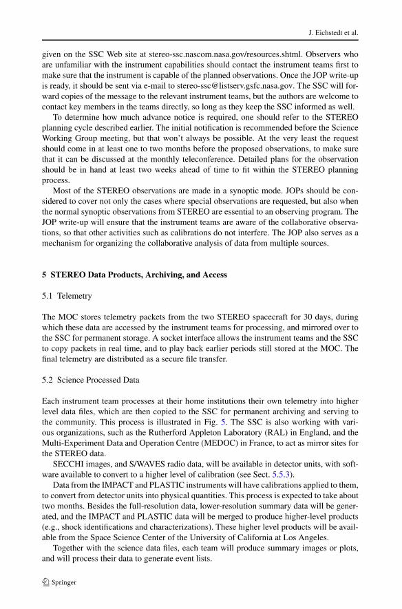
The MOC stores telemetry packets from the two STEREO spacecraft for 30 days, duringwhich these data are accessed by the instrument teams for processing, and mirrored over tothe SSC for permanent storage. A socket interface allows the instrument teams and the SSCto copy packets in real time, and to play back earlier periods still stored at the MOC. Thefinal telemetry are distributed as a secure file transfer.
5.2 Science Processed Data
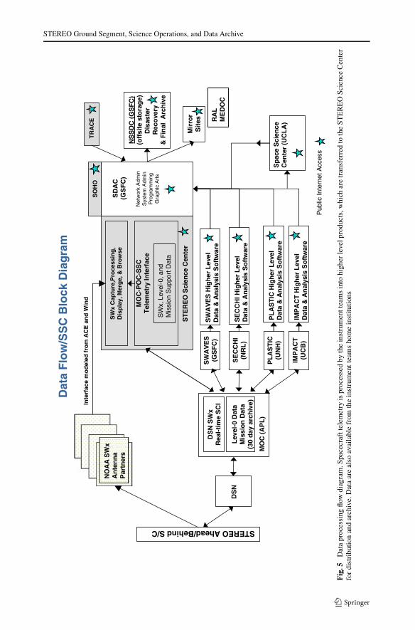
Each instrument team processes at their home institutions their own telemetry into higherlevel data files, which are then copied to the SSC for permanent archiving and serving tothe community. This process is illustrated in Fig. 5. The SSC is also working with vari-ous organizations, such as the Rutherford Appleton Laboratory (RAL) in England, and theMulti-Experiment Data and Operation Centre (MEDOC) in France, to act as mirror sites forthe STEREO data.
SECCHI images, and S/WAVES radio data, will be available in detector units, with soft-ware available to convert to a higher level of calibration (see Sect. 5.5.3).
Data from the IMPACT and PLASTIC instruments will have calibrations applied to them,to convert from detector units into physical quantities. This process is expected to take abouttwo months. Besides the full-resolution data, lower-resolution summary data will be gener-ated, and the IMPACT and PLASTIC data will be merged to produce higher-level products(e.g., shock identifications and characterizations). These higher level products will be avail-able from the Space Science Center of the University of California at Los Angeles.
Together with the science data files, each team will produce summary images or plots,and will process their data to generate event lists.
STEREO Ground Segment, Science Operations, and Data Archive
Fig
.5D
ata
proc
essi
ngflo
wdi
agra
m.S
pace
craf
ttel
emet
ryis
proc
esse
dby
the
inst
rum
entt
eam
sin
tohi
gher
leve
lpro
duct
s,w
hich
are
tran
sfer
red
toth
eST
ER
EO
Scie
nce
Cen
ter
for
dist
ribu
tion
and
arch
ive.
Dat
aar
eal
soav
aila
ble
from
the
inst
rum
entt
eam
sho
me
inst
itutio
ns

J. Eichstedt et al.
Fig. 6 Beacon processing flow diagram. Real-time telemetry packets, and interim beacon frames fromNOAA Antenna Partners, are merged together into a combined telemetry stream, and processed using soft-ware provided by the instrument teams
5.3 Space Weather Beacon Data
Along with the normal science telemetry, the instruments on the two STEREO spacecraftwill generate a special low-rate telemetry stream, known as the space weather beacon. Out-side of DSN contacts, this space weather beacon stream will continue to be broadcast at arate of approximately 633 bits per second. Various antenna partners around the world, co-ordinated by the National Oceanographic and Atmospheric Administration (NOAA), willcollect this telemetry and pass it on to the SSC in near-real-time via a socket connectionover the open Internet. The SSC will collate these data from the antenna partners, sortthe packets together into time-order, and run software provided by the instrument teamsto process this telemetry into data files. These data will be put on the SSC Web site atstereo-ssc.nascom.nasa.gov in near-real-time, within five minutes of receipt of all neededtelemetry. The space weather beacon data flow is shown in Fig. 6.
5.4 Ancillary Data
As well as the level-0 telemetry files, the STEREO Data Server at the MOC will make otherdata products available for mission planning purposes. These products include ephemerisfiles and other DSN products, observatory and instrument schedules, telemetry dictionaries,status reports, log files, and converted spacecraft housekeeping files. The most current fileswill be available from the STEREO Data Server, while the STEREO Science Center willserve as the long-term archive.
STEREO Ground Segment, Science Operations, and Data Archive
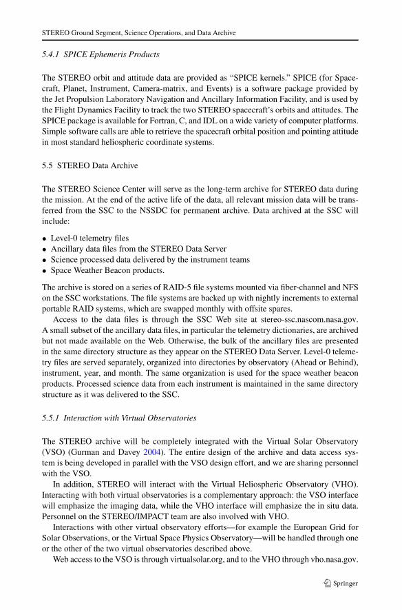
5.4.1 SPICE Ephemeris Products
The STEREO orbit and attitude data are provided as “SPICE kernels.” SPICE (for Space-craft, Planet, Instrument, Camera-matrix, and Events) is a software package provided bythe Jet Propulsion Laboratory Navigation and Ancillary Information Facility, and is used bythe Flight Dynamics Facility to track the two STEREO spacecraft’s orbits and attitudes. TheSPICE package is available for Fortran, C, and IDL on a wide variety of computer platforms.Simple software calls are able to retrieve the spacecraft orbital position and pointing attitudein most standard heliospheric coordinate systems.
5.5 STEREO Data Archive
The STEREO Science Center will serve as the long-term archive for STEREO data duringthe mission. At the end of the active life of the data, all relevant mission data will be trans-ferred from the SSC to the NSSDC for permanent archive. Data archived at the SSC willinclude:
• Level-0 telemetry files• Ancillary data files from the STEREO Data Server• Science processed data delivered by the instrument teams• Space Weather Beacon products.
The archive is stored on a series of RAID-5 file systems mounted via fiber-channel and NFSon the SSC workstations. The file systems are backed up with nightly increments to externalportable RAID systems, which are swapped monthly with offsite spares.
Access to the data files is through the SSC Web site at stereo-ssc.nascom.nasa.gov.A small subset of the ancillary data files, in particular the telemetry dictionaries, are archivedbut not made available on the Web. Otherwise, the bulk of the ancillary files are presentedin the same directory structure as they appear on the STEREO Data Server. Level-0 teleme-try files are served separately, organized into directories by observatory (Ahead or Behind),instrument, year, and month. The same organization is used for the space weather beaconproducts. Processed science data from each instrument is maintained in the same directorystructure as it was delivered to the SSC.
5.5.1 Interaction with Virtual Observatories
The STEREO archive will be completely integrated with the Virtual Solar Observatory(VSO) (Gurman and Davey 2004). The entire design of the archive and data access sys-tem is being developed in parallel with the VSO design effort, and we are sharing personnelwith the VSO.
In addition, STEREO will interact with the Virtual Heliospheric Observatory (VHO).Interacting with both virtual observatories is a complementary approach: the VSO interfacewill emphasize the imaging data, while the VHO interface will emphasize the in situ data.Personnel on the STEREO/IMPACT team are also involved with VHO.
Interactions with other virtual observatory efforts—for example the European Grid forSolar Observations, or the Virtual Space Physics Observatory—will be handled through oneor the other of the two virtual observatories described above.
Web access to the VSO is through virtualsolar.org, and to the VHO through vho.nasa.gov.

J. Eichstedt et al.
5.5.2 Uniform Data Format
Data from the STEREO instruments will be available in one of two standard file formats.Image data from the SECCHI instrument will be provided in the Flexible Image Trans-port System (FITS) format (Hanisch et al. 2001), while data from IMPACT, PLASTIC, andS/WAVES will be provided in the Common Data Format (CDF) (Goucher et al. 1994). Useof standardized formats simplifies the data analysis, and opens the data to a wide range ofsoftware tools. Conversion programs between the CDF and FITS formats are available.
5.5.3 Data Analysis Software
During the planning for the SOHO mission, it was realized that there were a number ofuseful data analysis packages that had been developed for previous missions, and that itwould be highly advantageous to collect all these packages into a single system. This led tothe development of the Solar Software Library (Freeland and Handy 1998), also known asSolarSoft or SSW. STEREO software, both for the mission as a whole, and for the individualinstruments, will also be delivered as part of the SolarSoft package. Thus, users will havea single unified way of downloading software for each of the STEREO instruments, as wellas for other solar missions.
Another advantage of being part of the SolarSoft library is the rich collection of softwarealready existing in the library, which is available both to the software developers of eachinstrument team, as well as to the individual scientist.
Within the SolarSoft library will be a separate directory tree for STEREO software. Be-neath this top-level STEREO directory will be separate directories for each of the fourSTEREO instruments, for the SSC, plus a generic (“gen”) STEREO-wide directory. Themain concentration will be on IDL software, but the SolarSoft system can also be used todistribute software written in other languages, such as Fortran or C source code.
Acknowledgements The authors thank Joseph Gurman and Peter Schroeder for helpful discussions on theinteraction between the STEREO Science Center and the Virtual Observatories.
References
J.D. Bohlin, K.J. Frost, P.T. Burr, A.K. Guha, G.L. Withbroe, Sol. Phys. 65, 5–14 (1980)A. Driesman, S. Hynes, Space Sci. Rev. (2007, this volume)S.L. Freeland, B.N. Handy, Sol. Phys. 182, 497–500 (1998)G. Goucher, J. Love, H. Leckner, in Solar–Terrestrial Energy Program. The Initial Results from STEP Fa-
cilities and Theory Campaigns. Proceedings of the 1992 STEP Symposium/5th COSPAR Colloquium,1994, p. 691
J.B. Gurman, A.R. Davey, in Proceedings of the SOHO 15 Workshop: Coronal Heating, 2004, pp. 583–586R.J. Hanisch, A. Farris, E.W. Greisen, W.D. Pence, B.M. Schlesinger, P.J. Teuben, R.W. Thompson,
A. Warnock III, Astron. Astrophys. 376, 359–380 (2001)O.C. St. Cyr, L. Sánchez-Duarte, P.C.H. Martens, J.B. Gurman, E. Larduinat, SOHO Ground Segment, Sci-
ence Operations, and Data Products. Sol. Phys. 162, 39–59 (1995)