stereotactic body radiotherapy - uthgsbsmedphys.org body... · stereotactic body radiotherapy...
TRANSCRIPT

StereotacticBodyRadiotherapy
Presented by Adam MelanconIntroduction to Medical Physics 34/14/15

Whystereotactictherapyforbody?
• Stereotactic therapy has been highly effective in small brain metastases
• Ablative• Effective for radioresistanttumors
• Spares tissues with geometry rather than leveraging tissue repair with fractionation

WhatisSBRT?(TG101)

TighterMarginsarekey• Lung SBRT at MDACC
• 3 mm PTV (8 mm CTV)• Spine SBRT at MDACC
• 0 mm PTV (physician determined CTV)
• SBRT at other institutions• 5 mm PTV (no CTV)

ReducingMargins
• Accurate treatment delivery (extra machine QA)
• Patient Immobolization• Target Localization
• Interfractional – between fractions• Intrafractional – during fractions

AnatomyoftheSBRTtreatmentmachine
Portal Imager
Gradicule tray
kVp Imager
kVpSource
Treatment isocenter
Imaging isocenter
MV Source

Novalis• IR fiducials for initial setup
• Orthogonal oblique imaging (during treatment)

Cyberkinfe (TG135)• Compact 6 MV linac• Either fixed cones or variable circular collimator (IRIS)
• Orthogonal oblique imaging (during treatment)

TG142mechanicalisocenter <1mm
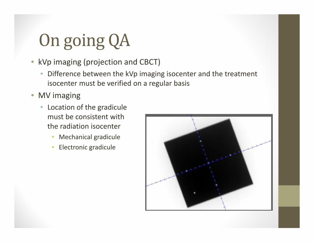
OngoingQA• kVp imaging (projection and CBCT)
• Difference between the kVp imaging isocenter and the treatment isocenter must be verified on a regular basis
• MV imaging• Location of the gradiculemust be consistent with the radiation isocenter
• Mechanical gradicule• Electronic gradicule

WinstonLutzTest• Tests the coincidence of kV, mV, and mechanical isocenters
BB
Radionics target
pointer

VarianIsocal
• Tests Iso coincidences and corrects panel positions per gantry angle
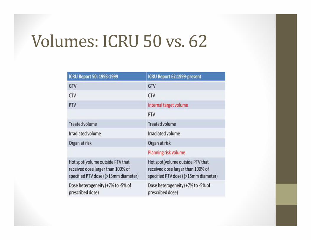
Volumes:ICRU50vs.62


Multiplephaseimagingexpansions(examplefromnon‐stereotactictreatment)
Conventional ITV based targeting
CTV=GTV + 8 mm
PTV=CTV+15 mm 7 mm setup8 mm motion
CTV 1=GTV 1 + 8 mm
PTV = ITV + 10 mm 7 mm setup3 mm motion
ITV = CTV 1+CTV 2
Prado Bucci
ICRU 50 ICRU 62

Uncertaintieseffectmargins(nonSBRTmargins)
Thoracic Service
Balter
Whataremarginsfor?
• Margins account for errors in RT• Error: any deviation between planned and executed treatments
• Errors are caused by:• Target delineation • Setup Uncertainties• Target Motion

EffectsofRandomandSystematicErrors
• Random errors tend to cancel out over a number of fractions• Examples: daily setup uncertainty, organ motion
• Systematic errors do not• This is why these are more important• As random errors are reduced systematic errors become more important
• Examples: Single sampling of initial CT, Radiation Isocenter alignment vs laser vs OBI vs CBCT

Howarethesemarginsdetermined?
This will guarantee that 90% of patients in a population receive a minimum cumulative CTV dose of at least 95% of the prescribed dose
vanHerk formulaMargins‐2.5*systematic + 0.7*random

Simulation• CT
• Contrast CT for liver• 4DCT for correction of lung motion
• MR• Brain Mets• Prostate staging
• PET• High sensitive for identifying sites of disease• Insufficient resolution for precise target delineation
Oxford University Press Journal of the ICRU 2010;10:41-53
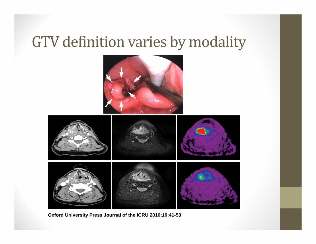
GTVdefinitionvariesbymodality

Comparison among various modalities for the definition of a primary-rectal-tumor GTV before (left), during concomitant chemoradiotherapy (center), and after radiation
therapy (right).
Oxford University Press Journal of the ICRU 2010;10:41-53
© International Commission on Radiation Units and Measurements 2010

Different images of a breast cancer as obtained by different methods (note that the different figures are not reproduced to identical scales).
Oxford University Press Journal of the ICRU 2004;4:25-37
© International Commission on Radiation Units and Measurements 2004
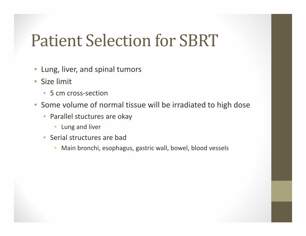
PatientSelectionforSBRT• Lung, liver, and spinal tumors• Size limit
• 5 cm cross‐section• Some volume of normal tissue will be irradiated to high dose
• Parallel stuctures are okay • Lung and liver
• Serial structures are bad• Main bronchi, esophagus, gastric wall, bowel, blood vessels
OrganMotion
•Breathing•Peristalsis•Organ filling and emptying
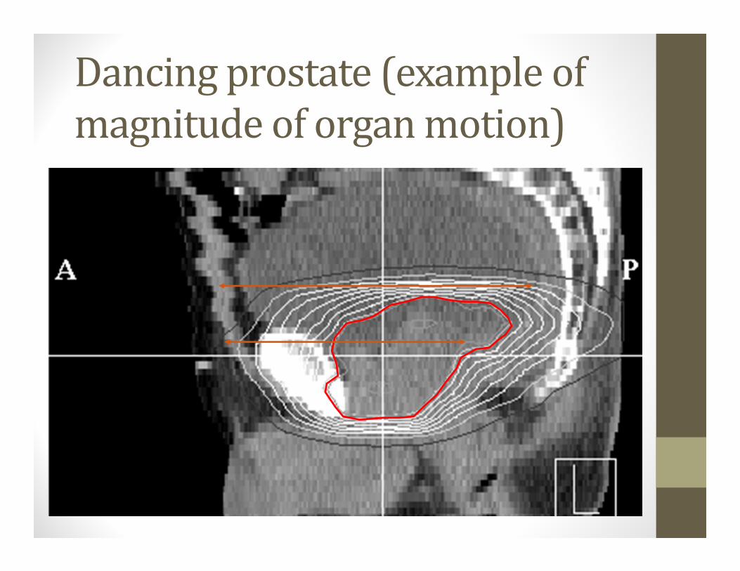
Dancingprostate(exampleofmagnitudeoforganmotion)

TechniquesThatManageRespiratoryMotion• Motion‐Encompassing
• ITV concept, treat the track of motion
• Respiratory‐Gating• Radiation on at particular portion of breath cycle (gate)• Residual motion within gate, longer treatment time
• Breath‐Hold• A form of gating with immobilization• Reduced motion and other benefits
• Forced Shallow‐Breathing – abdominal compression• Pressure to the abdomen reduces diaphragmatic excursions
• Respiration‐Synchronized• radiation beams dynamically follow tumor

Motion‐EncompassingMethods• Slow CT (Average CT)
• Multiple respiration phases are recorded per slice• Capturing motion that occurred during the time the vortex was scanned• Planning on a geometry (dataset) representative treatment • Motion blurring
• Inhale and exhale breath‐hold CT• Inhale and exhale breath‐hold scan + FB scan• Using MIP to obtain the tumor motion–encompassing volume
• Less blurring, but capture only part of the breath cycle
• 4D CT• Fast scan to capture multiple scans per slice within a breath cycle• Data can be used to reconstruct multiphase, average and MIP CTs

Twocommonapproachestoexternalmonitoringofrespiration:
Measurement of abdominal height
Measurement of abdominal diameter
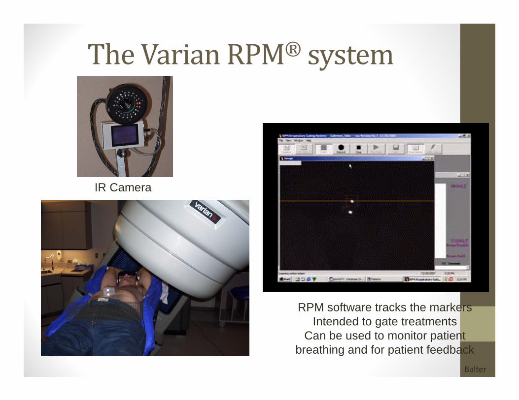
TheVarianRPM® system
IR Camera
IR Reflectors RPM software tracks the markersIntended to gate treatments
Can be used to monitor patient breathing and for patient feedback
Balter

Cinebased4DCT• The scanner is used in cine mode (time sequence of axial scans at each location)
• Each couch position (generally multiple detector rows) is sampled for greater than the one respiratory cycle (typical cine time: 5 sec)
• The patient’s respiratory cycle is monitored during image acquisition.• A sorter computer is used to extract phase binned images for each detector position based on the recorded respiratory trace.
• The result: a series of 3D data sets each representing a different respiratory phase.
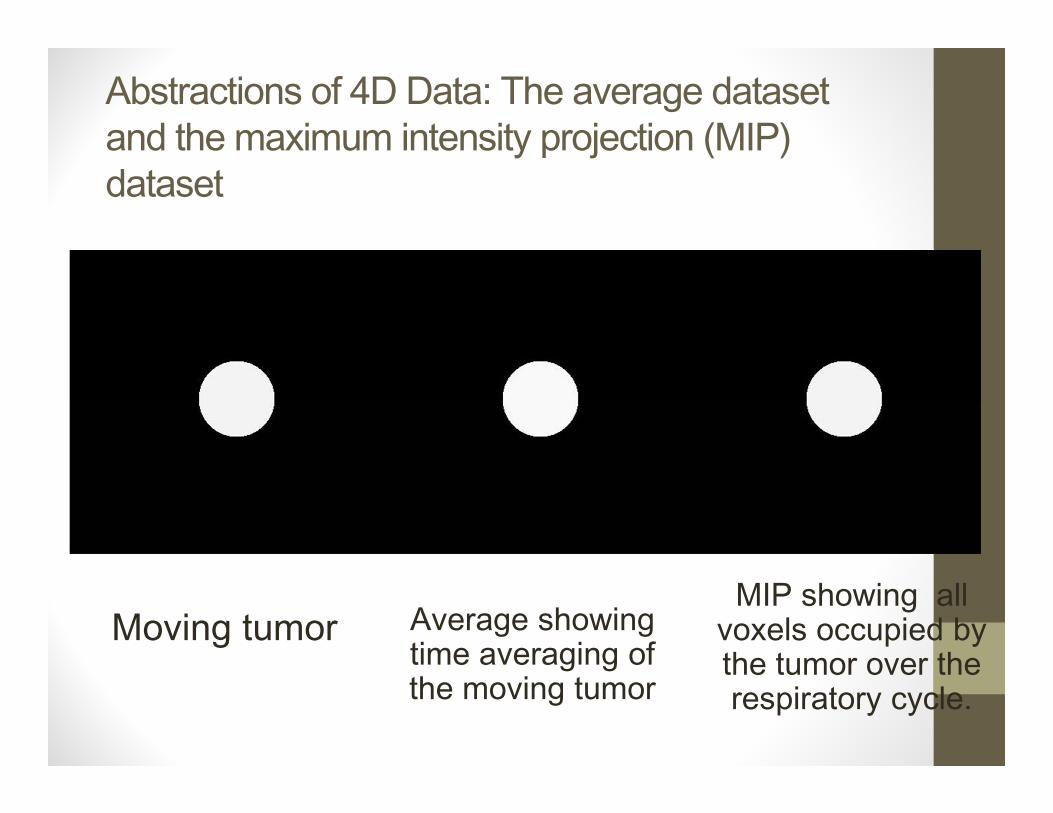
Abstractions of 4D Data: The average dataset and the maximum intensity projection (MIP) dataset
Moving tumor Average showing time averaging of the moving tumor
MIP showing all voxels occupied by the tumor over the respiratory cycle.
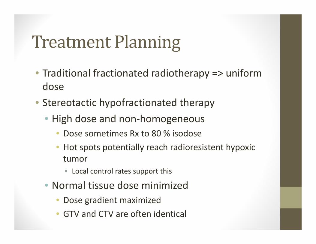
TreatmentPlanning• Traditional fractionated radiotherapy => uniform dose
• Stereotactic hypofractionated therapy• High dose and non‐homogeneous
• Dose sometimes Rx to 80 % isodose• Hot spots potentially reach radioresistent hypoxic tumor• Local control rates support this
• Normal tissue dose minimized• Dose gradient maximized• GTV and CTV are often identical

Treatmentplanning• Multiple non‐overlapping beams
• Restrict entrance dose to less than 30%• Isotropic dose fall‐off, except when adjacent to critical structure
• Choice of beam energy• 6MV is nice trade off between penetration and lateral electron scatter
• Grid Size• 2 or 3 mm grid size minimum a must
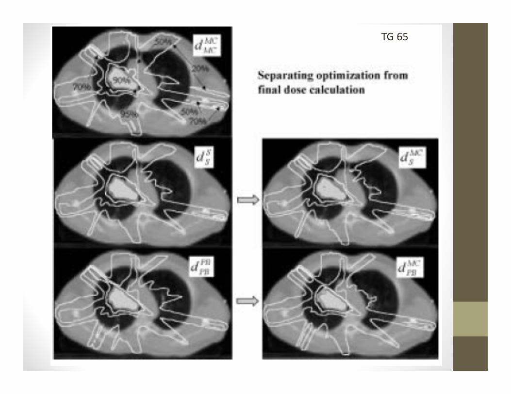
• Calculation algorithm• Must account for heterogeneities

TG 65
TG 65

TumorLung Lung


Multiplenon‐coplanarbeams

Conventional Blocking SBRT Blocking
Modifiedblocking

IMRTforimprovinginhomogeneity
Distance Distance
Rel
ativ
e In
put (
Dos
e) F
luen
ce
Rel
ativ
e D
ose
at tu
mor
GTV
CTV/PTV
CTV/PTV
GTV
CTV/PTV
CTV/PTV
GTV
CTV/PTV
CTV/PTV
GTV
CTV/PTV
CTV/PTV

VMATforconformingdoseClinical IMRT Plan SmartArc Plan

BiologicalEffectiveDose(BED)
• BED = nd 1+d/(α/β)• BED:
• 72 Gy: 60 Gy in 30 Fx (Conventional RT)• 84 Gy: 70 Gy in 35 Fx• 96 Gy: 60 Gy in 10 Fx• 106 Gy: 48 Gy in 4 Fx (Japan Oncology Group. I/C)• 112.5 Gy: 50 Gy in 4 Fx (MD Anderson, PTV)• 119 Gy: 70 Gy in 10 Fx (MD Anderson/Beijing, GTV)• 180 Gy: 60 Gy in 3 Fx (RTOG, 80% Isodose)
J.Chang

Bioeffect basedtreatmentplanning
• BED – biologically equivalent dose• NTD ‐ normalized total dose• EUD – equivalent uniform dose• All based on linear quadratic model, which may not model the biology at stereotactic dose levels
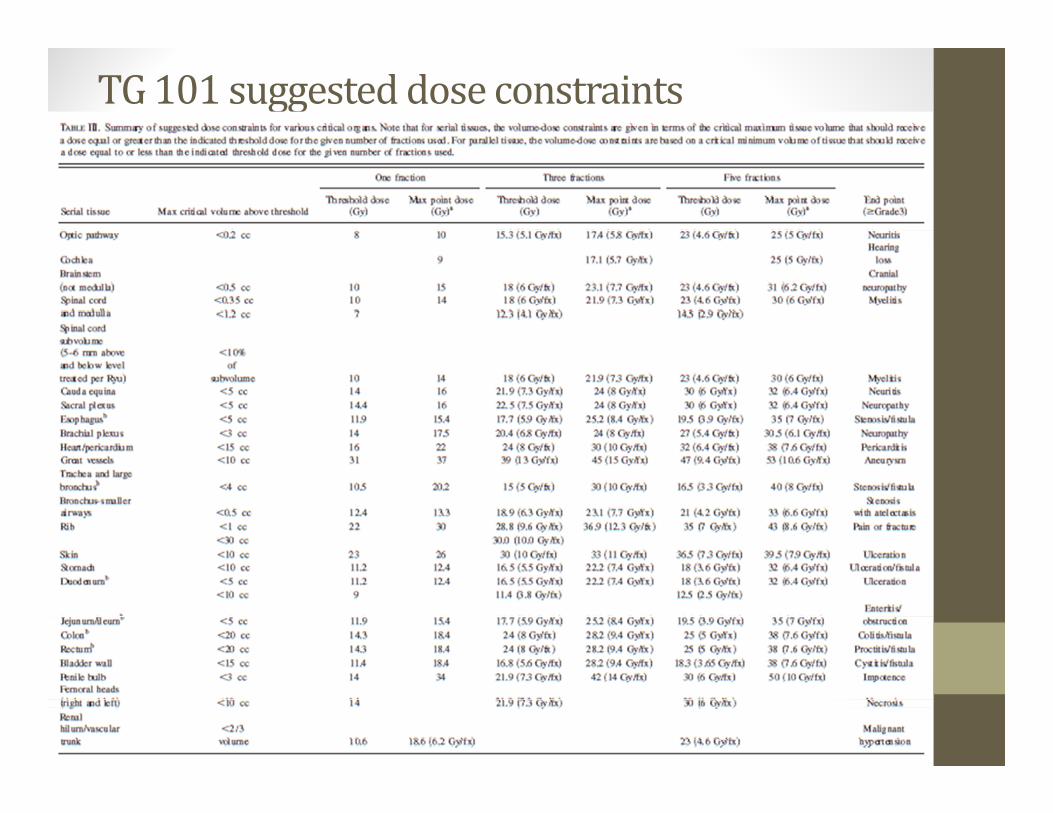
TG101suggesteddoseconstraints

ToleranceDosesfor50Gyin4fx
Brooks

Furtherhypofractionationreducestolerance(RTOG0915)
34 Gy x 1 12 Gy x 4
Change in fractionation can cut in half the dose constraints

Methodsofin‐roomsetup
• Rigid Immobolization• Projection imaging
• With fiducials• With gating
• Volumetric imaging• CT‐on‐rail• CBCT• MR (future)

Immobilization
Stereotactic immobilization, not intended for localization, does a
good job of immobilization.
Conventional immobilization, marking on skin. Not particularly
good for localization or immobilization.

ProjectionImaging• Can be MV or kVp• Can be gated with the same system as gates the treatment beam
• Can often not directly visualize the treatment site
• There are commercial systems that offer either real‐time or near time orthogonal imaging

In‐roomvolumetricimaging
• Allows direct visualization of many type of tumors (but not all)
• CT‐on Rails• CBCT• Generally can only be gated under breath‐hold
• New MR‐linac coming soon
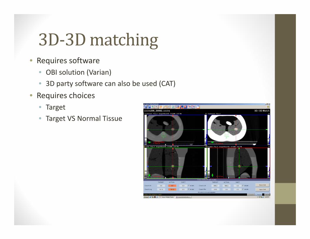
3D‐3Dmatching• Requires software
• OBI solution (Varian)• 3D party software can also be used (CAT)
• Requires choices• Target• Target VS Normal Tissue
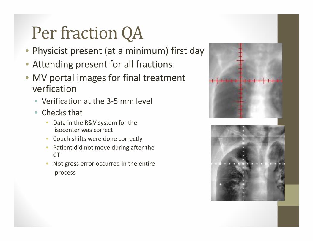
PerfractionQA• Physicist present (at a minimum) first day• Attending present for all fractions • MV portal images for final treatment verfication• Verification at the 3‐5 mm level• Checks that
• Data in the R&V system for theisocenter was correct
• Couch shifts were done correctly• Patient did not move during after the
CT• Not gross error occurred in the entire
process

• SBRT for improved control, patient convenience, and improved patient throughput
• Leverages geometric conformality to reduce margins and spare normal tissue
• Margins are managed with• Reduced machine tolerances• Immobolization• Localization
• Risk of morbidity is increased• Direct supervision of treatment is necessary
Conclusions