steve saunders ed wicklein ibis group inc. principal ... · 02.06.2015 · principal technologist,...
TRANSCRIPT

11/11/2017
1
Steve Saunders
IBIS Group Inc.
Ed Wicklein
Principal Technologist,Carollo Engineers
top entry impeller submersible mixers pumped jet mixers

11/11/2017
2
•In the past 20 years, CFD has emerged as an attractive choice forsimulating systems that employ mechanical mixing.
•This is due to two elements in physical modeling that can drive up itscost.
•Scaling laws are difficult to satisfy with mechanical mixers.
•Through-flow models may require special water use permitting.
Holy Trinity of Physical Modeling
Osborne Reynolds
Re: ratio between inertial andviscous forces
William Froude
Fr: ratio between inertial andgravitational forces
Moritz Weber
We: ratio between inertial and surfacetension forces
gl
vFr
vlRe
lvW e
2
•open channel flows•pump sumps
•weir flows•surface penetrating screens/filters
•rotating elements•internal flows

11/11/2017
3
•Scaling laws•Re, Fr and We based laws cannot be satisfied simultaneously.
•Model mixer impeller scaling is based on Re and is rarely smaller than 4 to 1
•Model basin scaling is based on Fr and can be as much as 10 or 20 to 1depending on available floor space.
•Through flow models•No recirculation means high water consumption and large quantities of water
discharging into the local sewer system
•Receiving utility may take issue with tracer chemicals used
Meshing
•Mixer jets are round in crosssection, so using unstructuredtetrahedral or polyhedral mesh isinevitable.
•If possible, use a hybrid mesh withhex cells orthogonal to the flowwhere steep gradients occur.

11/11/2017
4
Symmetry plane water surface colored by velocitymagnitudem/s
Boundary Conditions – Water Surface
Rigid lid water surface boundary condition isadequate for most mechanical mixingapplications.
A symmetry plane best represents a planarair/water interface.
The symmetry plane acts like a wall in that nomass may pass through it, but it is frictionlessand no boundary layer forms on it.
Boundary Conditions – Propeller Mixer Input
Sliding mesh (SM) – transient model with an accuraterepresentation of the propeller rotating incrementally with eachcomputational time step
Multiple reference frame (MRF) – steady state model with anaccurate representation of the propeller “frozen” in time.
Multiple reference frame with mixing plane (MRF+MP) – samesteady state model with an accurate representation of the propelleras MRF, but with a mixing plane to blend out individual bladewakes.
Momentum source model (MSM) – steady state model with theimpeller replaced by a “puck” shape. The fluid domain within thepuck accelerates the flow and gives it the axial, radial and tangentialvelocity profiles produced by the rotating propeller.
Börgesson, T. Fahlgren, M. M echanicsofFluidsinM ixing, 2001

11/11/2017
5
What is a mixing plane?
Developed by turbo machinery modelers who wantedto analyze individual stator/rotor passages.
Blends out wakes of individual blades bycircumferentially averaging flow properties.
Facilitates the use of small steady state models forrapid optimization of blade shapes
Department of IndustrialEngineeringUniversity of Florence
Ansys Inc. Fluent User Manual
Mixing plane used in an axial machine
Mixing plane used in centrifugal machine
Boundary Conditions – Propeller Mixer Input
Sliding mesh (SM) – best approximation of the real physics,but computationally burdensome.
Multiple reference frame (MRF) – a popular methodrecommended by Fluent among other CFD softwarevendors, but test cases performed by Börgesson andFahlgren showed poor reproduction of the mixer jet.
Multiple reference frame with mixing plane (MRF+MP) –significant improvement to mixer jet simulation, howeverBörgesson and Fahlgren observed computational instabilityin cross current applications.
Momentum source model (MSM) – good reproduction ofthe mixer jet and computationally efficient. The downsideis the user must obtain velocity profile data.
Börgesson, T. Fahlgren, M. M echanicsofFluidsinM ixing, 2001
Boundary Conditions – Propeller Mixer Input

11/11/2017
6
Boundary Conditions – Mixer Input
Evaluation of the Momentum Source Model Against Data Collected in the Field
Velocity measurements taken by means of ultrasonic probe froma full scale denitrification basin compare quite favorably with theCFD simulation results.
Cylindrical denitrification tank 17.9m dia. filled to 4.3m depth and equipped with a 2.5mdia. Low speed mixer
CFD Simulation
probe locationssuperimposed oncontour plots
Field Data
measurementplanes
Börgesson, T. Fahlgren, M. M echanicsofFluidsinM ixing-BringingM athem aticalM odelingClosetoR eality, Scientific Impeller No. 6, 2001
Simulation Parameters
Solids - Aside from identifying slow moving regions where
solids may settle and accumulate, many clients do notinclude treatment of suspended solids in their CFDmodeling scope. There is, however, a caveat…
Studies of mixing systems running with clear water willpredict higher mixing efficacy than the same systems withsuspended solids included in their simulation parameters.
If suspended solids content is known, their presence shouldbe simulated by means of a user defined function thatincludes density coupling.
Turbulence - For free shear flows, that is, jets acting in
tanks or basins, the Realizable K-Epsilon equations havebeen demonstrated to be robust and reliable.
streakline plot of slidingmesh propeller model usingRKE turbulence equations

11/11/2017
7
Case Study: Common Anoxic Basin Feeding 10 Parallel Aeration Lanes
screened sewageinflow
RASinflow
7 – 8 top entry mixers
The real world basin has 7 or 8 (depending on brand selected) top entry mixers.
Mixer propeller A
Sliding Mesh Propeller Sub Models
Case Study: Common Anoxic Basin Feeding 10 Parallel Aeration Lanes
Mixer propeller B
Tops are pressure inletboundaries.
Cylinder sides are pressureoutlet boundaries.
Floor boundaries are wallswith no slip
Hybrid mesh with structured hex in thecylinder and unstructured tet in the propellerdomain

11/11/2017
8
2015 FLOW-3D Americas Users Conference
rotating impellers replicated bymomentum sources
Case Study: Common Anoxic Basin Feeding 10 Parallel Aeration Lanes
frozen in time snapshot of slidingmesh model
steady state momentumsource model
Case Study: Common Anoxic Basin Feeding 10 Parallel Aeration Lanes
Looking at the Results
Mixing Efficacy Observed with Streakline Plots
Streaklines show bulk flow patterns and accelerations
With pressure, velocity and turbulence equationsturned off, a time dependent simulation is runwherein a tracer (non-reacting scalar) is allowedprogress through the flow continuum.
Qualitative results can be shown with the graphicoutput that CFD produces.
Quantitative results can be recorded by applying somestatistics to the data base.
Streaklines colored by tracer concentration
Streaklines colored by velocity magnitude
logarithmic scale allows for theillustration of a broad range ofvelocity magnitudes

11/11/2017
9
Histogram of velocity distributionwithin the common mixing basinN .B:Cellsizem ustbeaccountedforinhistogramgeneration.
Cumulative distribution of velocitywithin the common mixing basin
0.00
0.01
0.02
0.03
0.04
0.05
0.06
0.07
0.08
0.09
0.00 0.20 0.40 0.60 0.80 1.00
percentofvolum e
velocity (m /s)
mixerA mixerB
0.0
0.1
0.2
0.3
0.4
0.5
0.6
0.7
0.8
0.9
1.0
0 20 40 60 80 100
velocity (m /s)
percent ofvolum e
mixer A
mixer B
Case Study: Common Anoxic Basin Feeding 10 Parallel Aeration Lanes
Looking at the Results
Velocity Distribution
static mixer in an inflow pipe
injection lances
degree of mixing downstream of injection lances

11/11/2017
10
Case Study: Dispersion of a Disinfectant in a Serpentine Contact Tank
Disinfectant isintroduced by a singlepipe at the inflow tothe contact tank.
deviation from targetconcentration inpercent
Disinfectant concentrationdeviation is greater than 50% inthe first few passages of the tank.
Case Study: Dispersion of a Disinfectant in a Serpentine Contact Tank
Cross-channel baffles promote a rotating zoneopposite the tank inlet and top-to-bottomdispersion through the water column.
Disinfectant concentration deviation isless than 10% throughout the tank.

11/11/2017
11
Steve Saunders IBIS Group [email protected]
https://ibisgroupcfd.com/
Case Studies of Activated Sludge Mixing Analysis UsingPassive Geometry, Jet and Air Mixing IncorporatingSolids Transport
1. Mixing in anoxic zones
2. Jet and diffused aeration activated sludge mixing in a SBR
3. Activated Sludge Mixing in an Oxidation Ditch Process Conversion

11/11/2017
12
•3 anoxic zones, 5-hp floating mixers in each
•2 ABs IS in summer; 3 ABs IS in winter
•RAS & MLE combined in chimney in Zone 1

11/11/2017
13
July 8,2014
Normal (2 AB i.s.)
Zone 1-3
0 to 3.5’
Christm asDay 2013
Flow Conditions Low (3 AB i.S.)
Mixers off 1 Zone
Solids blanket depth 9 - 12'
Zone1 onJuly 8,2014 Zone2 onJuly 8,2014
11/11/2017
14
0 . 0 0 0
0 . 0 0 5
0 . 0 1 0
0 . 0 15
0 . 0 2 0
0 . 0 25
0 . 0 30
0 . 0 35
0 : 0 0 6: 0 0 1 2 : 0 0 1 8 : 0 0 0 : 0 0
Po
we
rL
eve
l,W
/m3
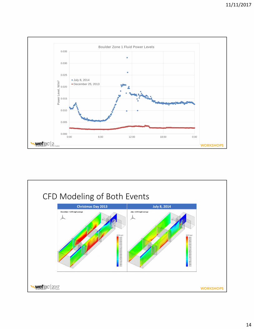
Boulder Zone 1 Fluid Power Levels
Ju ly 8 , 2 0 14
D ec ember25, 2 0 13
Christm asDay 2013 July 8,2014

11/11/2017
15
CoV P ow erlevel,W /m 3 (hp/m ilgal)
Location Decem ber25th
July8th
Decem ber25th
July 8th
Zone 1 12.9% 10.6% 0.0025(0.013)
0.0123 (0.059)
Zone 2 15.1% 5.7% 0.0500(0.254)
0.1630 (0.827)
Zone 3 25.6% 18.8% 0.0094(0.048)
0.0409 (0.207)

11/11/2017
16
•Estimated power requirement: 0.75 - 1.0 hp/mil gal for 5% CoV
•Use flow energy to suspend solids
•Design considerations•Zone design to target minimum velocity
•Adjustable gates maintain minimum flow velocities and power levelsover a greater range of flow conditions
•Solid retardation in unmixed systems may help N and P removal(in-line ML fermentation)
Case Study 2Jet mixing and aeration in a sequencing batch reactor (SBR)*
Jet nozzles for mixing
Pump suction outlets
Air modeled with multiphase model
Solids transport, settling, and densityimpact modeled by UDF
*Samstag, Wicklein, et al. (2012)
Mesh projected onto model surfaces.

11/11/2017
17
Case Study 2Jet mixing and aeration in a sequencing batch reactor (SBR)*
JetM ixingH ead ers withA irInjec tion
A irM ixingS how sHighT urbulence
S urfaceofT ankinA noxicP haseshow ingthepresenceofalgae

11/11/2017
18
Condition Location Time,minutes
CoV
Air On Main Platform - 3.8%Air Off Main Platform 0 4.2%Air Off Main Platform 25 14.5%Air Off Pump Ladder 42 19.9%Air Off Main Platform 66 5.0%Air Off Pump Ladder 75 42.6%Air Off Main Platform 83 39.5%
S im ulatedP um pedM ixingP rofile S im ulatedA erationP rofile

11/11/2017
19
Density-coupled
Solids transport model calculates thelocal solids concentration based onflow regime.
The influence of the local solidsconcentration on the local density isthen iteratively calculated.
This approach was verified by the fieldsolids profile test data.
Density-coupled N eutraldensity
Neutral density simulation dramatically over-predicts the degree of mixing.

11/11/2017
20
Existing(2.5m /secJet)
3.0 m /secJet
3.5 m/sec Jet 4.0 m/sec Jet
JetVelocity M ix CriterionP ow erL evel
(hp/M G)P ow erL evel
(W /m 3)
2.5 m/sec jet velocity 50% Max Deviation 39 7.7
3.0 m/sec jet velocity 40% Max Deviation 66 13.0
3.5 m/sec jet velocity 12% Max Deviation 105 20.7
4.0 m/sec jet velocity< 10% MaxDeviation 156 30.8
To meeta 10 perc entd eviation c riterion wou ld req u ire fou rtimes more powerthan c u rrently ins talled .

11/11/2017
21
Case Study 3Mechanical and air mixing in an oxidation ditch process conversion
Ditch converted to once throughreactor
Walls added to isolate Zones
Anoxic and Zone 1 have mechanicalmixers
Fine bubble aeration in Zones 1 to 4
15HpS ubm ersibleHorizontalP ropeller 10 HpVerticalHyperboloid

11/11/2017
22

11/11/2017
23
Solids mixing results showed similar coefficient of variation forboth types of mixer.
Mixer Anoxic Zone Zone 1
Horizontal 1.9 1.5
Vertical 2.2 1.5
Horizontal Vertical
Mixer Power (hp) Power (hp)
1 7.8 4.5
2 7.8 4.6
3 9.4 4.6
4 9.5 6.7
5 6.6
Total 34.5 27.0

11/11/2017
24
Air introduced on flat sections of the bottom creates rollingpattern over sloped sides.
Zone A irFlow (cfm )
1 1285
2 812
3 560
4 200

11/11/2017
25
Aerated zones have relatively high velocity, keepingeverything well mixed.
•To be realistic, CFD analysis of activated sludge mixing needs toincorporate solids settling and transport and coupling of density tothe solids concentration profile.
•Mixing with air is well handled with a two-phase solution. Mixing ofsolids is well handled using a two-way (active) scalar approach.
•This approach has been applied to several of the major types ofmixers in the current marketplace.
