stick-slip whirl interaction d. h. van campen in ... · stick-slip whirl interaction ... vibrations...
TRANSCRIPT
tiontedfluid
of amplen ay the
odelstick-nu-ling
R. I. Leinee-mail: [email protected]
D. H. van Campen
Department of Mechanical Engineering,Eindhoven University of Technology,P.O. Box 513, 5600 MB Eindhoven,
The Netherlands
W. J. G. KeultjesShell International Exploration
and Production b.v.,Volmerlaan 8, P.O. Box 60, 2280 AB Rijswijk,
The Netherlands
Stick-slip Whirl Interactionin Drillstring DynamicsThis paper attempts to explain the complicated behavior of oilwell drillstring mowhen both torsional stick-slip and lateral whirl vibration are involved. It is demonstrathat the observed phenomena in experimental drillstring data could be due to theforces of the drilling mud. A Stick-slip Whirl Model is presented which consistssubmodel for the whirling motion and a submodel for the stick-slip motion, both as sias possible. The Stick-slip Whirl Model is a simplification of a drillstring confined iborehole wall with drilling mud. The model is as simple as possible to expose onlbasic phenomena but is discontinuous. Bifurcation diagrams of this discontinuous mfor varying rotation speeds reveal discontinuous bifurcations. The disappearance ofslip vibration when whirl vibration appears is explained by bifurcation theory. Themerical results are compared with the experimental data from a full-scale drilrig. @DOI: 10.1115/1.1452745#
a
r
e
n
t
a
e
x
ill-pre-
o-leisandm
ll-in
f aheerstive
ndd atViathatergyn-
am-r,
lye-ally
atednrly
t ofs
etingehe
he
t;
1 Introduction
Deep wells for the exploration and production of oil and gasdrilled with a rock-cutting tool driven from the surface by a sleder structure of pipes, called the drillstring~Fig. 1!. Drillstringvibrations are an important cause of premature failure of dstring components and drilling inefficiency. Stick-slip vibratiocauses violent torsional vibration of the drillstring and whirl leato lateral vibrations with large amplitudes. Extensive researchthis subject has been conducted for the last four decades,theoretically@1–7# and experimentally@8–12#. Whirling motionof a drill collar section has been studied by@1,2,7#. Models fortorsional stick-slip motion of a drillstring were presented in@2#and extensively analyzed by@3,6#. Most of the experimental in-vestigations were only based on field measurements recordethe surface@8–11#. Stick-slip vibrations can indeed be detectfrom the surface, at least in a straight well, but detailed informtion about the mechanism downhole cannot be obtained. Dohole measurements, briefly presented in this paper, reveal sslip vibration coexisting with whirl vibration. Uncertainty existon the downhole mechanism which determines whether stick-or whirl will be prevalent. This paper presents a low-dimensiodynamical model, describing stick-slip and whirl in its most eementary form. This model aims at explaining the basic nonlindynamics phenomena observed in downhole experiments.model system is analyzed with the methods presented in@13–16#which are shortly summarized in Appendix A. It is demonstrathat the model system exhibits several types of discontinuousfurcations. We will discuss in Section 10 the possible meritsthis paper to the insight into drillstring vibration.
Dynamical problems of drillstrings are analyzed in industry uing linear models for critical rotary speeds and buckling loadslarge finite element models@2#, which give quantitative informa-tion and can help to give practical recommendations to circuvent drilling problems. The finite element models are howevercomplex ~nonlinear large displacement, finite rotation, many dgrees of freedom! that it is very difficult to obtain insight whycertain vibrational phenomena occur. Small low degree of frdom models, which can be analyzed with analytical methods,provide~to some degree! qualitative insight in a specific complephenomenon occurring in reality. The aim of the Stick-slip WhModel, proposed in this paper, is to explain qualitatively the o
Contributed by the Technical Committee on Vibration and Sound for publicain the JOURNAL OF VIBRATION AND ACOUSTICS. Manuscript received Nov. 2000Revised Oct. 2001. Associate Editor: A. F. Vakakis.
Copyright © 2Journal of Vibration and Acoustics
ren-
ill-ndson
both
d atda-
wn-tick-sslipall-earThe
edbi-of
s-nd
m-soe-
e-can
irlb-
served phenomenon of stick-slip to whirl transitions in a real drstring. The model is kept as simple as possible and does nottend to give any quantitative information.
The principles of oilwell drilling are first briefly explained inSection 2. Downhole measurements, which reveal stick-slip mtion and whirl in a drillstring, are presented in Section 3. A simpmathematical model for the investigation of stick-slip and whirlconstructed and analyzed in Sections 4 to 9. The theoreticalnumerical results will be compared with results obtained fromeasurements in Section 10.
2 Principles of Oilwell DrillingOil and gas wells are predominantly drilled using rotary dri
ing. The basic elements of a rotary drilling system are shownFig. 1. A rotary drilling system creates a borehole by means orock-cutting tool, called a bit. The oldest type of rotary bit is troller-cone bit which essentially comprises three metal rollcovered with hard steel teeth that crush the rock. An alternatype of bit is the PDC~Polycrystalline Diamond Compact! bitconsisting of a steel body with inserts made of artificial diamoand tungsten carbide. The energy to drive the bit is generatethe surface by a motor with a mechanical transmission box.the transmission the motor drives the rotary table: a large discacts as kinetic energy storage. The medium to transport the enfrom the surface to the bit is formed by a drillstring, mainly cosisting of drill pipes: slender tubes, about 9 m~30 ft.! long,coupled with threaded connections, having a typical outside dieter of 127 mm~5 in.! and a wall thickness of 9 mm. Howevesmaller~e.g. 3.5 in.! and larger~6.5 in.! drill pipe diameters arealso used.
The lowest part of the drillstring, the Bottom-Hole-Assemb~BHA!, consists of thick-walled tubulars, called drill collars. Dpendent on the diameter of the hole, these drill collars usuhave an inner diameter of 2.5–3 in.~64–76 mm! and an outerdiameter of 4.75 in.–9.5 in.~120–240 mm!. The BHA can beseveral hundreds of meters long, and often contains dedicdownhole tools. The drill collars in the BHA are kept in positioby a number of stabilizers, which are short sections with neathe same diameter as the bit.
The drilling process requires a compressive force on the bisome 104– 106 N. This dynamic force is commonly denoted aWeight On Bit ~WOB!, although force-on-bit would be a morappropriate name. The entire drillstring is suspended by a hoissystem, consisting of a travelling block with hook, drilling linand winch. The drillstring rests with the bit on the bottom of thole and is pulled at the hook by a force called the hookload. T
ion
002 by ASME APRIL 2002, Vol. 124 Õ 209
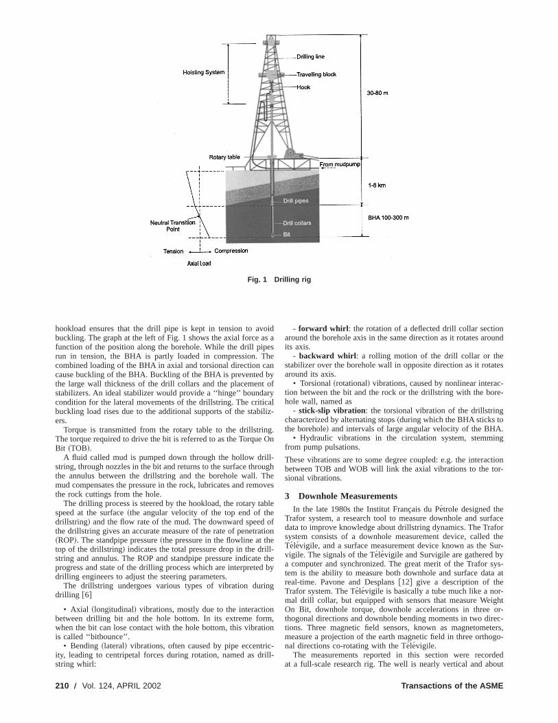
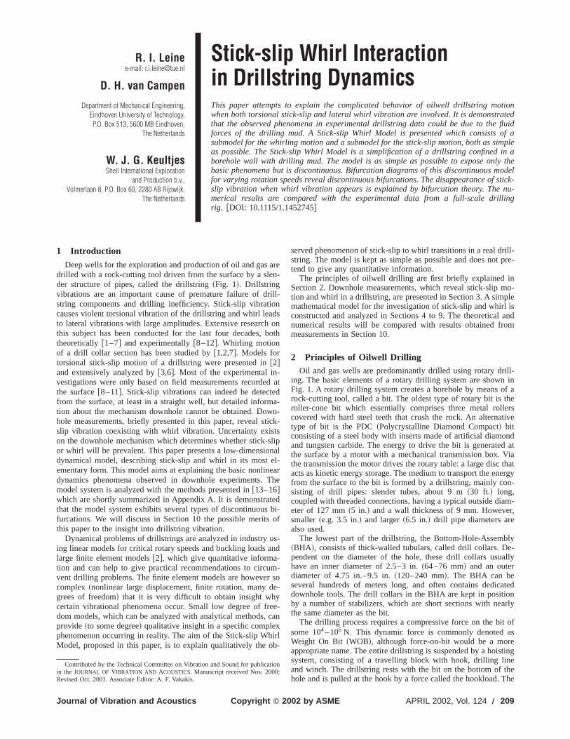
Fig. 1 Drilling rig
o
e
a
r
i
l
e
eled
n
nmi
cr
nund
tes
c-re-
.g
ctionr-
faceforthe
Sur-yys-
a at
-ghtor-ec-ters,go-
dedout
hookload ensures that the drill pipe is kept in tension to avbuckling. The graph at the left of Fig. 1 shows the axial force afunction of the position along the borehole. While the drill piprun in tension, the BHA is partly loaded in compression. Tcombined loading of the BHA in axial and torsional direction ccause buckling of the BHA. Buckling of the BHA is prevented bthe large wall thickness of the drill collars and the placementstabilizers. An ideal stabilizer would provide a ‘‘hinge’’ boundacondition for the lateral movements of the drillstring. The criticbuckling load rises due to the additional supports of the stabers.
Torque is transmitted from the rotary table to the drillstrinThe torque required to drive the bit is referred to as the TorqueBit ~TOB!.
A fluid called mud is pumped down through the hollow dristring, through nozzles in the bit and returns to the surface throthe annulus between the drillstring and the borehole wall. Tmud compensates the pressure in the rock, lubricates and remthe rock cuttings from the hole.
The drilling process is steered by the hookload, the rotary taspeed at the surface~the angular velocity of the top end of thdrillstring! and the flow rate of the mud. The downward speedthe drillstring gives an accurate measure of the rate of penetra~ROP!. The standpipe pressure~the pressure in the flowline at thtop of the drillstring! indicates the total pressure drop in the dristring and annulus. The ROP and standpipe pressure indicatprogress and state of the drilling process which are interpretedrilling engineers to adjust the steering parameters.
The drillstring undergoes various types of vibration duridrilling @6#
• Axial ~longitudinal! vibrations, mostly due to the interactiobetween drilling bit and the hole bottom. In its extreme forwhen the bit can lose contact with the hole bottom, this vibratis called ‘‘bitbounce’’.
• Bending~lateral! vibrations, often caused by pipe eccentriity, leading to centripetal forces during rotation, named as dstring whirl:
210 Õ Vol. 124, APRIL 2002
ids as
henyofyalliz-
g.On
l-ughheoves
ble
oftion
l-theby
g
,on
-ill-
- forward whirl : the rotation of a deflected drill collar sectioaround the borehole axis in the same direction as it rotates aroits axis.
- backward whirl : a rolling motion of the drill collar or thestabilizer over the borehole wall in opposite direction as it rotaaround its axis.
• Torsional~rotational! vibrations, caused by nonlinear interation between the bit and the rock or the drillstring with the bohole wall, named as
- stick-slip vibration : the torsional vibration of the drillstringcharacterized by alternating stops~during which the BHA sticks tothe borehole! and intervals of large angular velocity of the BHA
• Hydraulic vibrations in the circulation system, stemminfrom pump pulsations.
These vibrations are to some degree coupled: e.g. the interabetween TOB and WOB will link the axial vibrations to the tosional vibrations.
3 Downhole MeasurementsIn the late 1980s the Institut Franc¸ais du Pe´trole designed the
Trafor system, a research tool to measure downhole and surdata to improve knowledge about drillstring dynamics. The Trasystem consists of a downhole measurement device, calledTelevigile, and a surface measurement device known as thevigile. The signals of the Te´levigile and Survigile are gathered ba computer and synchronized. The great merit of the Trafor stem is the ability to measure both downhole and surface datreal-time. Pavone and Desplans@12# give a description of theTrafor system. The Te´levigile is basically a tube much like a normal drill collar, but equipped with sensors that measure WeiOn Bit, downhole torque, downhole accelerations in threethogonal directions and downhole bending moments in two dirtions. Three magnetic field sensors, known as magnetomemeasure a projection of the earth magnetic field in three orthonal directions co-rotating with the Te´levigile.
The measurements reported in this section were recorat a full-scale research rig. The well is nearly vertical and ab
Transactions of the ASME
v
r/
tocy
e
a
o
rt
one.lip
irlby
d
heraglac-ic-estion
thee-
r ther
an
htlyltingest
nt
d
thend
got
omod.
1080 m deep. Various tests with different WOB and angularlocity of the rotary table were conducted. A few tests are usedthis paper, all conducted with the same drillstring setup. The dstring consisted of 5 in. drill pipe, 8 in. drill collars and a 12 1in. roller-cone bit.
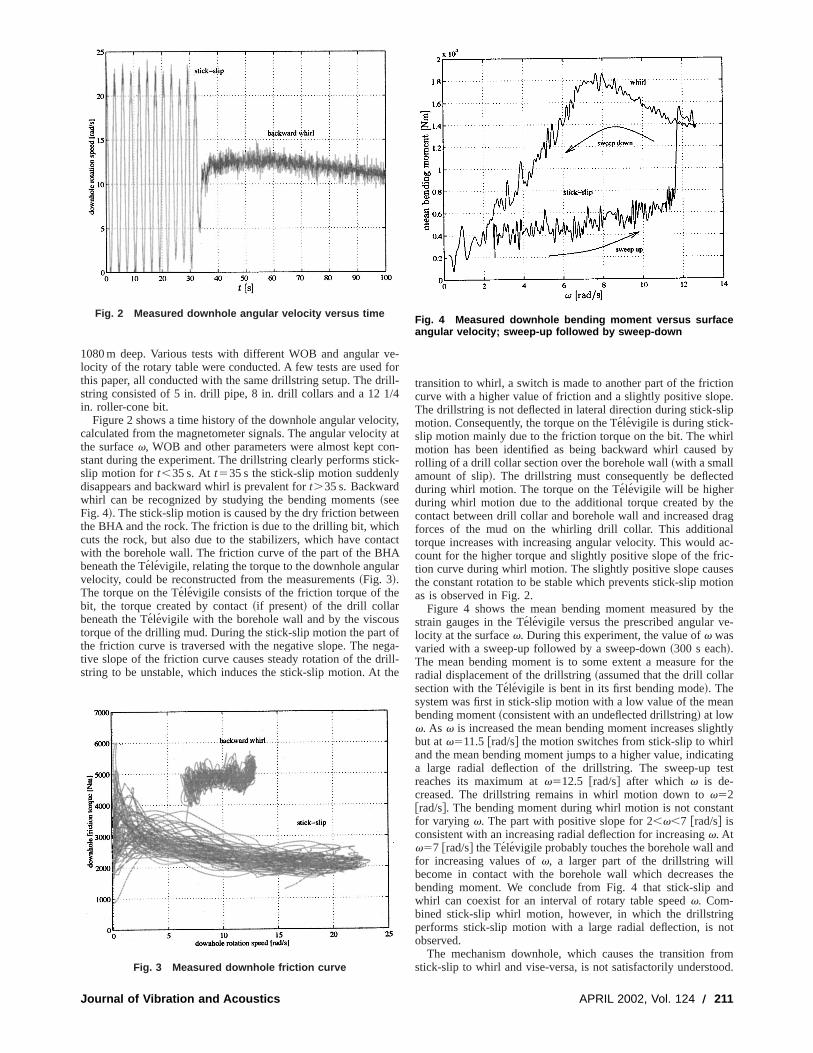
Figure 2 shows a time history of the downhole angular veloccalculated from the magnetometer signals. The angular velocithe surfacev, WOB and other parameters were almost kept cstant during the experiment. The drillstring clearly performs stislip motion for t,35 s. At t535 s the stick-slip motion suddenldisappears and backward whirl is prevalent fort.35 s. Backwardwhirl can be recognized by studying the bending moments~seeFig. 4!. The stick-slip motion is caused by the dry friction betwethe BHA and the rock. The friction is due to the drilling bit, whiccuts the rock, but also due to the stabilizers, which have conwith the borehole wall. The friction curve of the part of the BHbeneath the Te´levigile, relating the torque to the downhole angulvelocity, could be reconstructed from the measurements~Fig. 3!.The torque on the Te´levigile consists of the friction torque of thebit, the torque created by contact~if present! of the drill collarbeneath the Te´levigile with the borehole wall and by the viscoutorque of the drilling mud. During the stick-slip motion the partthe friction curve is traversed with the negative slope. The netive slope of the friction curve causes steady rotation of the dstring to be unstable, which induces the stick-slip motion. At
Fig. 2 Measured downhole angular velocity versus time
Fig. 3 Measured downhole friction curve
Journal of Vibration and Acoustics
e-forill-4
ity,y atn-k-
nhtactAr
sf
ga-ill-he
transition to whirl, a switch is made to another part of the fricticurve with a higher value of friction and a slightly positive slopThe drillstring is not deflected in lateral direction during stick-smotion. Consequently, the torque on the Te´levigile is during stick-slip motion mainly due to the friction torque on the bit. The whmotion has been identified as being backward whirl causedrolling of a drill collar section over the borehole wall~with a smallamount of slip!. The drillstring must consequently be deflecteduring whirl motion. The torque on the Te´levigile will be higherduring whirl motion due to the additional torque created by tcontact between drill collar and borehole wall and increased dforces of the mud on the whirling drill collar. This additionatorque increases with increasing angular velocity. This wouldcount for the higher torque and slightly positive slope of the frtion curve during whirl motion. The slightly positive slope causthe constant rotation to be stable which prevents stick-slip moas is observed in Fig. 2.
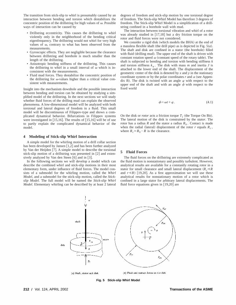
Figure 4 shows the mean bending moment measured bystrain gauges in the Te´levigile versus the prescribed angular vlocity at the surfacev. During this experiment, the value ofv wasvaried with a sweep-up followed by a sweep-down~300 s each!.The mean bending moment is to some extent a measure foradial displacement of the drillstring~assumed that the drill collasection with the Te´levigile is bent in its first bending mode!. Thesystem was first in stick-slip motion with a low value of the mebending moment~consistent with an undeflected drillstring! at lowv. As v is increased the mean bending moment increases sligbut atv511.5@rad/s# the motion switches from stick-slip to whirand the mean bending moment jumps to a higher value, indicaa large radial deflection of the drillstring. The sweep-up treaches its maximum atv512.5 @rad/s# after which v is de-creased. The drillstring remains in whirl motion down tov52@rad/s#. The bending moment during whirl motion is not constafor varying v. The part with positive slope for 2,v,7 @rad/s# isconsistent with an increasing radial deflection for increasingv. Atv57 @rad/s# the Televigile probably touches the borehole wall anfor increasing values ofv, a larger part of the drillstring willbecome in contact with the borehole wall which decreasesbending moment. We conclude from Fig. 4 that stick-slip awhirl can coexist for an interval of rotary table speedv. Com-bined stick-slip whirl motion, however, in which the drillstrinperforms stick-slip motion with a large radial deflection, is nobserved.
The mechanism downhole, which causes the transition frstick-slip to whirl and vise-versa, is not satisfactorily understo
Fig. 4 Measured downhole bending moment versus surfaceangular velocity; sweep-up followed by sweep-down
APRIL 2002, Vol. 124 Õ 211
rahh
t
e
s
m
h
n
a
oo
reeof
-
tor
h
s
the
aser,n a
eishe
The transition from stick-slip to whirl is presumably caused byinteraction between bending and torsion which destabilizesconcentric position of the drillstring for high values ofv. Possibleways of interaction can be caused by
• Drillstring eccentricity. This causes the drillstring to whiviolently only in the neighborhood of the bending criticeigenfrequency. The drillstring would not whirl for very higvalues ofv, contrary to what has been observed from tmeasurements.
• Gyroscopic effects. They are negligible because the clearabetween drillstring and borehole is much smaller thanlength of the drillstring.
• Anisotropic bending stiffness of the drillstring. This causthe drillstring to whirl in a small interval ofv which is in-consistent with the measurements.
• Fluid mud forces. They destabilize the concentric positionthe drillstring for v-values higher than a critical value consistent with measurements.
Insight into the mechanism downhole and the possible interacbetween bending and torsion can be obtained by studying aplified model of the drillstring. In the next sections we will studwhether fluid forces of the drilling mud can explain the observphenomena. A low-dimensional model will be analyzed with botorsional and lateral degrees of freedom in a fluid. This smmodel will be discontinuous of Filippov-type and shows a coplicated dynamical behavior. Bifurcations in Filippov systemwere investigated in@15,16#. The results of@15,16# will be of useto partly explain the complicated dynamical behavior of tmodel.
4 Modeling of Stick-slip Whirl InteractionA simple model for the whirling motion of a drill collar sectio
has been developed by Jansen@1,2# and has been further analyzeby Van der Heijden@7#. A simple model to describe the torsionstick-slip motion of a drillstring was presented in@2# and exten-sively analyzed by Van den Steen@6# and in @3#.
In the following sections we will develop a model which cadescribe the combined whirl and stick-slip motions in their melementary form, under influence of fluid forces. The model csists of a submodel for the whirling motion, called theWhirlModel, and a submodel for the stick-slip motion, called theStick-slip Model. The full model will be named theStick-slip WhirlModel. Elementary whirling can be described by at least 2 late
212 Õ Vol. 124, APRIL 2002
anthe
ll
e
ncehe
s
of-
tionim-yedthall-s
e
dl
nstn-
ral
degrees of freedom and stick-slip motion by one torsional degof freedom. The Stick-slip Whirl Model has therefore 3 degreesfreedom. The Stick-slip Whirl Model is a simplification of a drillstring confined in a borehole wall with mud.
The interaction between torsional vibration and whirl of a rowas already studied in@17,18# but a dry friction torque on therotor and fluid forces were not considered.
We consider a rigid disk~which models the BHA! at the end ofa massless flexible shaft~the drill pipe! as is depicted in Fig. 5~a!.The shaft and disk are confined in a stator~the borehole! filledwith fluid ~drilling mud!. The upper end of the shaft is driven witconstant rotation speedv ~constant speed of the rotary table!. Theshaft is subjected to bending and torsion with bending stiffneskand torsion stiffnesskw . The disk with massm and inertiaJ isattached to the lower end of the shaft. The displacement ofgeometric center of the disk is denoted byx andy in the stationarycoordinate system or by the polar coordinatesr anda ~see Appen-dix B!. The disk is twisted with an anglew with respect to theupper end of the shaft and with an anglef with respect to thefixed world
f5vt1w. (4.1)
On the disk orrotor acts a friction torqueTf ~the Torque On Bit!.The lateral motion of the disk is constrained by thestator. Therotor has a radiusR and the stator a radiusRb . Contact is madewhen the radial~lateral! displacement of the rotorr equalsRc ,whereRc5Rb2R is the clearance.
5 Fluid ForcesThe fluid forces on the drillstring are extremely complicated
the fluid motion is nonstationary and possibly turbulent. Howevanalytical results are available for a constantly rotating rotor istator for small clearance and small lateral displacement~Rc!Rand r !R! @19,20#. As a first approximation we will use thesanalytical results for nonstationary motion of a rotor whichconfined in a large stator for arbitrary lateral displacements. Tfluid force equations given in@19,20# are
Fig. 5 Stick-slip Whirl Model
Transactions of the ASME
-
:
heg
t
a
isces-
r
he
reicare
ofrlthe
i-
qua-
ed
2FF f x
F f yG5Fmf 0
0 mfG F xyG1F D vmf
2vmf DG F xyG
1Fc2~r ! 0
0 c2~r !G F xyG1F 2
v2
4mf
v
2D
2v
2D 2
v2
4mf
G FxyG
1F c1~r !v
2c2~r !
2v
2c2~r ! c1~r !
G FxyG , (5.1)
wheremf is the added fluid mass andD the fluid friction coeffi-cient.
The fluid forces, depicted in Fig. 5~b!, can be transformed topolar coordinates
F f r52mf S r 2a2r 2v2
4r 1var D2~D1c2~r !! r 2c1~r !r
(5.2)
F f a52mf~ ar 12r a2v r !2S a2v
2 D ~D1c2~r !!r .
The nonlinear functionsc1 and c2 depend on the radial displacementr. It is assumed~following @20#! that these functionsare analytic~with c1(0)5c2(0)50!. As a first approximation,only the following symmetric terms will be taken into account
c1~r !5B1r 2, c2~r !5B2r 2, (5.3)
whereB1 andB2 are constants.
6 Contact ForcesThe stator wall will induce normal and tangential forces~Fig.
5~b!! on the rotor if the radial displacement becomes larger tthe clearance,r .Rc . The normal contact force can be model~in its most simple form! to stem from a linear spring with sprinstiffnesskb ,
FbN5H kb~r 2Rc! r .Rc
0 r<Rc.(6.1)
The normal contact force induces a tangential contact force dudry friction between the rotor and the wall. We assume a consfriction coefficientmb . If the relative velocity between the rotoand the stator wall is nonzero, then the tangential contact forc
FbT52mb sign~v rel!FbN , v relÞ0, (6.2)
with the relative velocity being given byv rel5ar 1vR ~for con-stant rotation of the rotor!. During pure rolling (v rel50) the tan-gential contact force must be between
2mbFbN<FbT<mbFbN . (6.3)
The contact forces can be expressed in stationary coordinate
Fbx5~2FbTy2FbNx!/r , Fby5~FbTx2FbNy!/r . (6.4)
The friction due to rotor-stator contact can be treated numericby making use of theswitch model@21#.
6.1 Torques on the Disk. We assume that a dry frictiontorqueTf is acting on the rotor, which only depends on the anglar velocity f,
Tf52sgnfT0
11dufu. (6.5)
Journal of Vibration and Acoustics
and
e toantre is
s as
lly
u-
This relation between dry friction torque and angular velocitymotivated by Fig. 3. Contact between the rotor and stator induthe contact forcesFbN andFbT . The tangential contact force induces a torque on the rotor,
Tb5FbTR. (6.6)
The fluid forcesF f r andF f a of Eq. ~5.2! are derived for stationarymotion of the rotorf5v. We will assume that they also hold fononstationary motion,fÞv, and we replacev by f in Eq. ~5.2!,
F f r52mf S r 2a2r 2f2
4r 1far D 2~D1c2~r !! r 2c1~r !r
(6.7)
F f a52mf~ ar 12r a2f r !2S a2f
2 D ~D1c2~r !!r .
The fluid forcesF f r and F f a act on the rotor but their workinglines are through the origin. The forceF f a has therefore an arm2r and gives the torque
Td52F f ar . (6.8)
7 Whirl ModelIn this section we study only the Whirl Model. We assume t
rotor to rotate constantly~no torsional vibration!. This allows us tofind analytical results for the pure whirling motion, which aequilibria of the Whirl Model in polar coordinates and periodharmonic solutions in stationary coordinates. Polar coordinatestherefore more convenient for the Whirl Model. The equilibriathe Whirl Model are also equilibria of the total Stick-slip WhiModel but the eigenvalues of the Stick-slip Model may changestability.
7.1 Equations of Motion. The equations of motion for awhirling rotor with fluid and contact forces in stationary coordnates are
mx1cx1kx5F f x1Fbx (7.1)my1cy1ky5F f y1Fby ,
wherem is the rotor mass,k the lateral bending stiffness andc thelateral bending damping constant. In polar coordinates these etions become
m~ r 2a2r !1cr1kr5F f r2FbN (7.2)m~ ar 12r a !1car 5F f a1FbT .
Substitution of the fluid forces of Eq.~5.2! gives
ma~ r 2a2r !1~c1D1B2r 2! r 1S k2v2
4mf1mfva1B1r 2D r
52FbN (7.3)ma~ ar 12r a !1~c1D1B2r 2!ar
5mfv r 1~D1B2r 2!v
2r 1FbT ,
with ma5m1mf . This fourth-order system can be transforminto a third-order system with the whirl velocityV5a,
ma~ r 2V2r !1~c1D1B2r 2! r 1S k2v2
4mf1mfvV1B1r 2D r
52FbN (7.4)
ma~Vr 12rV!1~c1D1B2r 2!Vr
5mfv r 1~D1B2r 2!v
2r 1FbT .
APRIL 2002, Vol. 124 Õ 213
m
t
o
-
e
-
enes
or-
mal
he
-
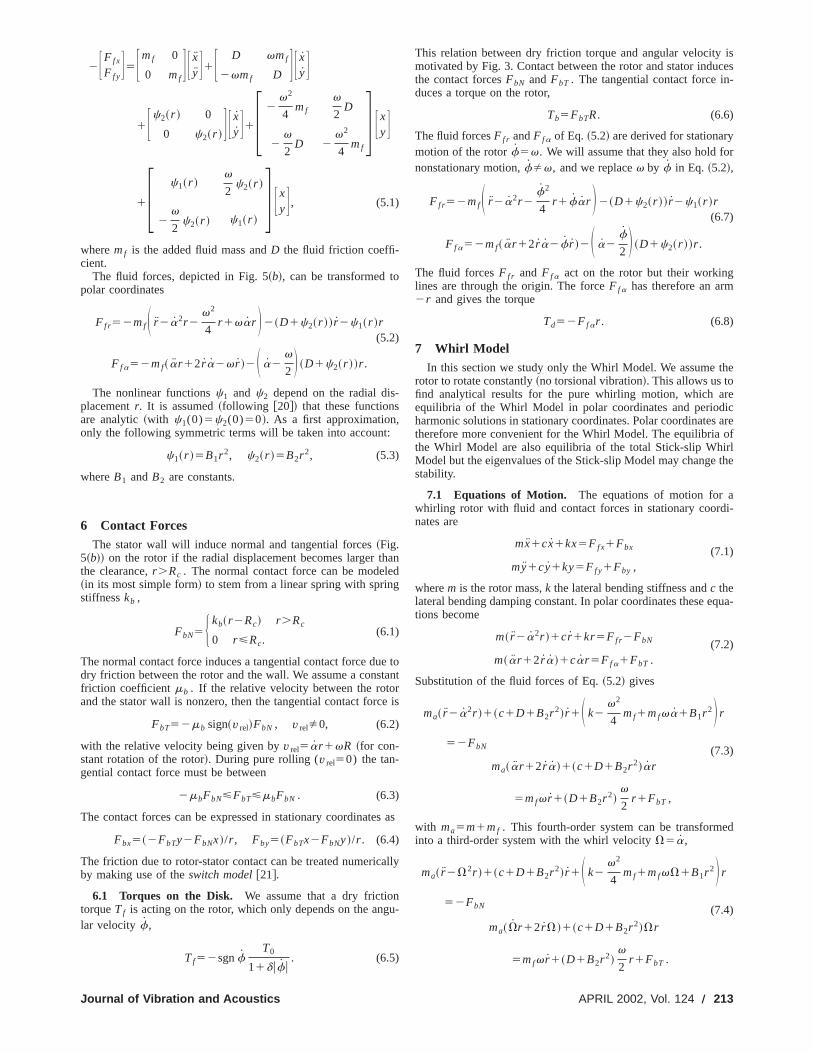
7.2 Equilibrium Without Contact. The equilibrium with-out contact (r e ,Ve) of Eq. ~7.4! has to obeyr 5 r 5V50 andr ,Rc . The whirl velocity can be derived from the second eqution of Eq. ~7.4!,
Ve5D1B2r e
2
c1D1B2r e2
v
2. (7.5)
Consequently, the rotor is whirling forward in the equilibriuwithout contact. The first equation of Eq.~7.4! gives
S k2v2
4mf1mfvVe2maVe
21B1r e2D r e50. (7.6)
Solving the latter equation gives two equilibrium branches ofsystem without contact. The first branch is the trivial solution
r e50, (7.7)
and the second branch can be derived from
k2v2
4mf1mfvVe2maVe
21B1r e250. (7.8)
The trivial branch becomes unstable when it meets the secbranch. We denote the frequency at which the trivial branchcomes unstable byvc . Substitution of Eqs.~7.5! and ~7.7! intoEq. ~7.8! givesvc
vc254k
~c1D !2
c2mf1D2m. (7.9)
Two limiting cases are of special interest: a! c.0 and D5B250, b! c50 andD.0, B2.0.
Case „a… implies that we consider the system to rotate infrictionless fluid. The rotor will not whirl due to the absencefluid friction,
Ve,a50. (7.10)
The quasi-static motion of the rotor gives
cre,a5S v2
4mf2kD r e,a2B1r e,a
3 . (7.11)
The two stationary solutions~for r e,a>0! are
r e,a50, r e,a5Av2
4mf2k
B1(7.12)
We conclude that case a! gives a supercritical pitchfork bifurcation (B1.0) at
vc,a52A k
mf(7.13)
Case„b… implies that we consider the system to have no structudamping but only fluid damping. The rotor will whirl with half throtation speed~1/2v-whirl!,
Ve,b51
2v. (7.14)
The quasi-static motion of rotor gives~with ma5m1mf!
~D1B2r e,b2 ! r e,b5S v2
4m2kD r e,b2B1r e,b
3 . (7.15)
The two stationary solutions~for r e,b>0! are
r e,b50, r e,b5Av2
4m2k
B1. (7.16)
214 Õ Vol. 124, APRIL 2002
a-
he
ondbe-
af
ral
We conclude that case~b! also gives a supercritical pitchfork bifurcation at twice the natural frequency,
vc,b52Ak
m. (7.17)
For mf /m,1 it can be shown thatvc,b,vc,vc,a . The pitch-fork bifurcation is shown in Fig. 6 for the parameter values givin Appendix C. The trivial branche1a is stable and meets thbifurcation~denoted by c! after which it is unstable and continueas e1b . From the bifurcation point starts a branch of stable fward whirl solutionse2 .
7.3 Equilibrium With Pure Rolling. The rotor rolls overthe stator wall without slipping under three conditions:
1. the relative velocity is zero,v rel5Vr 1vR50,2. positive normal contact force,FbN.0,3. the tangential contact force does not exceed the maxi
friction force, 2mbFbN<FbT<mbFbN .
The pure rolling equilibrium~r 5r p , V5Vp! has to obeyr 5 r5V50.
The whirl velocity can be derived from condition 1,
Vp52R
r pv. (7.18)
Consequently, the rotor rolls backward over the stator wall. Tequilibrium conditions give
2maVp2r p1S k2
v2
4mf1mfvVp1B1r p
2D r p
52FbN52kb~r p2Rc! (7.19)
and
~c1D1B2r p2!Vpr p5~D1B2r p
2!v
2r p1FbT . (7.20)
Substitution ofVp in Eq. ~7.19! gives a third-order polynomial inr p . If we neglect the nonlinear fluid termB1 , Eq. ~7.19! reducesto a second-order polynomial
S k1kb2v2
4mf D r p
22~kbRc1mfv2R!r p2mav2R250.
(7.21)
Solving for r p gives two roots of which only one fulfills condition 1,
Fig. 6 Whirl Model, equilibrium branches
Transactions of the ASME
r p5
kbRc1mfv2R1A~kbRc1mfv
2R!214mav2R2S k1kb2v2
4mf D
2S k1kb2v2
4mf D . (7.22)
i
x
dn
the
he
pure
elyforact
at
The limit of kb to infinity gives of course limkb→`
r p5Rc .
If we assume directly an infinitely stiff wall of the stator without neglectingB1 , then we can solve for the contact forces,
FbN5mav2R2
Rc2S k2
v2
4mf1B1Rc
2DRc1v2Rmf , (7.23)
FbT52~c1D1B2Rc2!vR2~D1B2Rc
2!v
2Rc . (7.24)
Equation~7.23! should fulfill condition 2,
v2.vb25
~k1B1Rc2!Rc
ma
R2
Rc1mf
1
4Rc1mfR
. (7.25)
If B1 is not too large, thenvb,vc,b .However, pure rolling nearv5vb is not possible because Eq
~7.24! has to fulfill condition 3. We define that condition 3violated atv5vd . Substitution of Eqs.~7.23! and ~7.24! into2mbFbN5FbT gives a second-order polynomial invd ,
2mbS ma
R2
Rc1mf S Rc
41RD Dvd
2
1S cR1~D1B2Rc2!S R1
Rc
2 D Dvd1mbRc~k1B1Rc2!50.
(7.26)
If the fluid damping (D, B2) and structural damping~c! are smallcompared to the dry friction caused bymb , then we can make thefollowing approximation
vd2'vb
21
cR1~D1B2Rc2!S R1
Rc
2 DmbS ma
R2
Rc1mf S Rc
41RD D vb . (7.27)
Fluid damping and structural damping cause thatvd.vb .The pure rolling branch for the parameter values of Appendi
is depicted in Fig. 6 as branche4 . The point at which the branchstops (v5vd) is denoted by d. The valueRc is taken as unity. Alarger value for the borehole stiffnesskb will cause the pure roll-ing branch to come closer tor 5Rc .
Branche2 , with stableforward whirling solutions without con-tact, is connected to branche4 , with stablebackwardwhirlingpure rolling solutions, by the unstable branche3 . Branche3 con-sists of equilibria with slipping contact.
7.4 Equilibrium With Slipping Contact. The relative ve-locity v rel between rotor and stator is positive for forward whirlinsolutions without contact~branche2!, whereas it is zero for purerolling solutions~branche4!. The relative velocity during slippingcontact~branche3! should be in between. There are two condtions for slipping:
1. the relative velocity is positive,v rel5Vr 1vR.0,2. positive normal contact force,FbN.0.
The slipping equilibrium~r 5r s , V5Vs! has to obeyr 5 r 5V50. The equilibrium conditions give
Journal of Vibration and Acoustics
-
.s
C
g
i-
2maVs2r s1S k2
v2
4mf1mfvVs1B1r s
2D r s52FbN ,
(7.28)
~c1D1B2r s2!Vsr s5~D1B2r s
2!v
2r s2mbFbN , (7.29)
whereFbN5kb(r s2Rc). This system of equations can be solveto give r s , which will not be done in this section. The insight cabe gained from other considerations. The limit ofkb to infinitygives of course
limkb→`
r s5Rc .
The branch of slipping equilibrium begins at the point whereequilibrium without contact touches the stator wallr e5Rc ~de-noted by f in Fig. 6! and the branch ends at the point where tpure rolling branch begins~point d!. Consequently, the slippingbranch connects the stable no-contact branch to the stablerolling branch. Of much interest is to knowhow the slippingbranch is located between the two end-points, which is closrelated to its stability. We therefore try to find an expression]r /]v at the point where the slipping branch and the no-contbranche2 connect. To simplify the results we will assumeB250. At the connection point to the no-contact branch we haver s5r e5Rc . The following equations hold at this point
Vs5Ve5D
c1D
v
2, (7.30)
S k2v2
4mf1mfvVe2maVe
21B1Rc2DRc50. (7.31)
We now differentiate Eq.~7.28! with respect tov. This gives
22maVs
]Vs
]vr s2maVs
2]r s
]v1S k2
v2
4mf1mfvVs1B1r s
2D ]r s
]v
1S 2v
2mf1mfVs1mfv
]Vs
]v12B1r s
]r s
]v D r s52kb
]r s
]v
(7.32)
and when we substitute Eqs.~7.30! and ~7.31!,
2ma
D
c1Dv
]Vs
]vRc1S 2
1
21
1
2
D
c1D1
]Vs
]v DmfvRc
52~2B1Rc21kb!
]r s
]v. (7.33)
Differentiating Eq.~7.29! gives
]Vs
]vr s1Vs
]r s
]v5
1
2
D
c1D S r s1v]r s
]v D2mbkb
c1D
]r s
]v
or
]Vs
]v5
1
2
D
c1D2
mbkb
c1D
1
Rc
]r s
]v. (7.34)
After substitution of Eq.~7.34! in Eq. ~7.33! we arrive at an ex-pression for]r s /]v,
APRIL 2002, Vol. 124 Õ 215
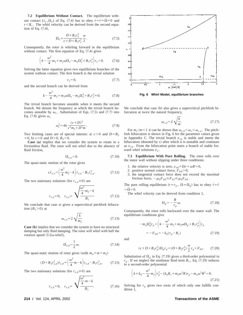
Fig. 7 Stick-slip Model
m
h
u
f
um
-
e
uid
as
lip
e.
.
lsity
art.e
n
uid
kbS 112B1
kbRc
22mbv
~c1D !2 ~mfc2mD! D ]r s
]v
51
2
vRc
~c1D !2 ~D2m1c2mf !. (7.35)
The limit of kb to infinity gives of course limkb→`
]r s /]v50. Two
limiting cases are of special interest:Case„a… c.0, D50 andkb@B1Rc
2
After substitution in Eq.~7.35! we obtain
kbS 12mbvmf
c D ]r s
]v5
1
2vRcmf . (7.36)
Consequently, when
mbvmf
c.1⇒ ]r
]v,0,
mbvmf
c,1⇒ ]r
]v.0.
Case„b… c50, D.0 andkb@B1Rc2
After substitution in Eq.~7.35! we obtain
kbS 11mbvm
D D ]r s
]v5
1
2vRcm. (7.37)
Consequently, it must hold that]r /]v.0.
The parameter values of the structural damping and fluid daing are c50.3 N/~ms) and D50.1 N/~ms). The numerical ex-ample is similar to case~a! with mbvmf /c.1. The derivative]r /]v at point f is therefore negative which causes the branche3to be unstable and to connect point d with point f directly. If tparameter values would be different, such thatmbvmf /c,1, thenbranche3 would start at point f with a positive slope as a stabbranch. It will at some point turn around and continue as anstable branch in the direction of point d.
Bifurcation points d and f are discontinuous saddle-node bications of the equilibrium branche22e32e4 . An eigenvaluejumps over the imaginary axis through the origin at those bifcation points. At bifurcation point d, being the transition frocontact to no-contact, this is caused by the non-smoothness onormal contact force Eq.~6.1!. At bifurcation point f, being thetransition from slip to stick, this is caused by the non-smoothnof the tangential contact force, Eq.~6.2!. Remark the angle between the branches at a discontinuous bifurcation point.
216 Õ Vol. 124, APRIL 2002
p-
e
len-
ur-
r-
f the
ess
8 Stick-Slip ModelIn this section we study only the Stick-slip Model. We assum
the rotor to rotate concentricly in the stator~no lateral vibration,r 50!. As there is no radial displacement, the torques due to flforces and contact forces vanish~Td50, Tb50!. The equation ofmotion for pure torsional motion is
Jw52kww1Tf . (8.1)
The Stick-slip Model has an unstable equilibrium branch~w5Tf(v)/k, w50!, which corresponds to the trivial equilibriumbranch ~r 50, w5Tf(v)/k! of the full Stick-slip Whirl Model.The trivial equilibrium branch was denoted in the Whirl Modelbranche1 ~Fig. 6!.
8.1 Periodic Stick-Slip Vibrations. The periodic solutionsof the Stick-slip Model are also periodic solutions of the Stick-sWhirl Model ~compare Eq.~8.1! with Eq. ~9.1! for r 5Tb5Td50!. The periodic stick-slip vibration is depicted in Fig. 7~a!. Thetwist w is on the horizontal axis and the angular velocityf5w1v on the vertical axis. The limit cycle is traversed clock-wisThe slip part of the motion takes place atf.0. When the velocityis decreasing during the slip part, it arrives atf50 and continueswith backward rotation (f,0). This backward slip motion isfollowed by the stick partf50, which completes the limit cycle
The branch of periodic stick-slip solutions (p1) is numericallydetermined for varying values ofv and depicted in Fig. 7~b!. Theminimal value of f is set on the vertical axis. For the triviaequilibrium branch holds minf5v and this branch is unstable athe friction torqueTf decreases with increasing angular velocf. The periodic stick-slip branch has a minimal value off, beingsmaller or equal than zero depending on the backward slip pAs can be seen from Fig. 7~b!, backward rotation becomes morpronounced at higher values ofv.
9 Stick-Slip Whirl ModelThe Stick-slip Model and the Whirl Model will be combined i
this section which gives the Stick-slip Whirl Model.
9.1 Equations of Motion. Combining the lateral and thetorsional model and taking into account the nonstationary flforces, fluid torque and contact torque~Section 6.1! gives thefollowing set of equations of motion
Transactions of the ASME
sE
l
d ei-
ly
ainsione
-in
lsor-irl
l-
ma~ r 2V2r !1~c1D1B2r 2! r 1S k2f2
4mf1mffV1B1r 2D r
52FbN
ma~Vr 12rV!1~c1D1B2r 2!Vr
5mff r 1~D1B2r 2!f
2r 1FbT (9.1)
Jw52kww1Tf1Tb1Td .
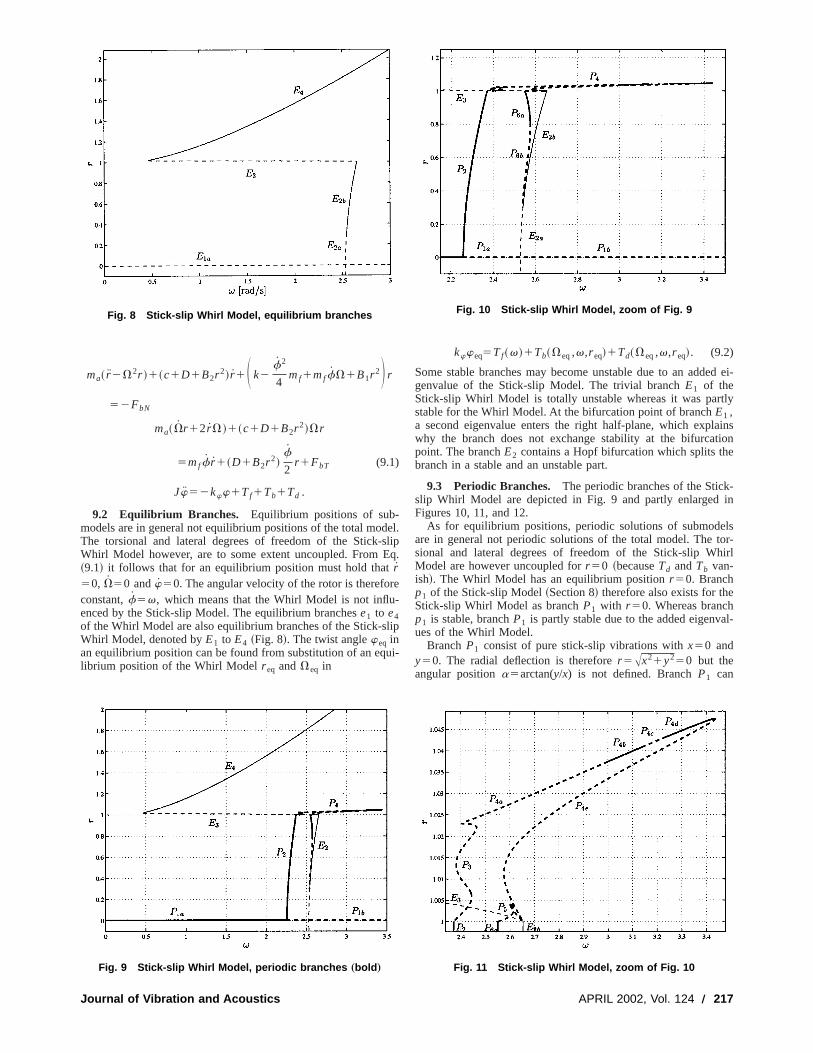
9.2 Equilibrium Branches. Equilibrium positions of sub-models are in general not equilibrium positions of the total modThe torsional and lateral degrees of freedom of the Stick-Whirl Model however, are to some extent uncoupled. From~9.1! it follows that for an equilibrium position must hold thatr50, V50 andw50. The angular velocity of the rotor is thereforconstant,f5v, which means that the Whirl Model is not influenced by the Stick-slip Model. The equilibrium branchese1 to e4of the Whirl Model are also equilibrium branches of the Stick-sWhirl Model, denoted byE1 to E4 ~Fig. 8!. The twist angleweq inan equilibrium position can be found from substitution of an eqlibrium position of the Whirl Modelr eq andVeq in
Fig. 9 Stick-slip Whirl Model, periodic branches „bold …
Fig. 8 Stick-slip Whirl Model, equilibrium branches
Journal of Vibration and Acoustics
el.lipq.
e-
ip
ui-
kwweq5Tf~v!1Tb~Veq,v,r eq!1Td~Veq,v,r eq!. (9.2)
Some stable branches may become unstable due to an addegenvalue of the Stick-slip Model. The trivial branchE1 of theStick-slip Whirl Model is totally unstable whereas it was partstable for the Whirl Model. At the bifurcation point of branchE1 ,a second eigenvalue enters the right half-plane, which explwhy the branch does not exchange stability at the bifurcatpoint. The branchE2 contains a Hopf bifurcation which splits thbranch in a stable and an unstable part.
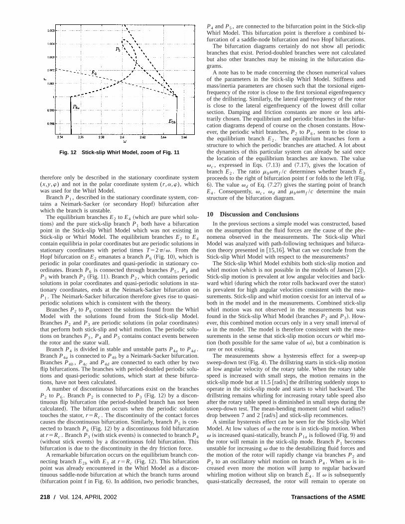
9.3 Periodic Branches. The periodic branches of the Stickslip Whirl Model are depicted in Fig. 9 and partly enlargedFigures 10, 11, and 12.
As for equilibrium positions, periodic solutions of submodeare in general not periodic solutions of the total model. The tsional and lateral degrees of freedom of the Stick-slip WhModel are however uncoupled forr 50 ~becauseTd andTb van-ish!. The Whirl Model has an equilibrium positionr 50. Branchp1 of the Stick-slip Model~Section 8! therefore also exists for theStick-slip Whirl Model as branchP1 with r 50. Whereas branchp1 is stable, branchP1 is partly stable due to the added eigenvaues of the Whirl Model.
BranchP1 consist of pure stick-slip vibrations withx50 andy50. The radial deflection is thereforer 5Ax21y250 but theangular positiona5arctan(y/x) is not defined. BranchP1 can
Fig. 10 Stick-slip Whirl Model, zoom of Fig. 9
Fig. 11 Stick-slip Whirl Model, zoom of Fig. 10
APRIL 2002, Vol. 124 Õ 217
o
n
s
r
u
.
h
e
s
s
o
lipi-s.ic
latedia-
luesndigen-ncyorlarrbi-ur-ow-
outncelue
sedphe-hirla-
d
ck-rea-
slipas
ofea-
p-up
lethe
helsothe
irl
d
ard
on
therefore only be described in the stationary coordinate sys(x,y,w) and not in the polar coordinate system (r ,a,w), whichwas used for the Whirl Model.
BranchP1 , described in the stationary coordinate system, ctains a Neimark-Sacker~or secondary Hopf! bifurcation afterwhich the branch is unstable.
The equilibrium branchesE2 to E4 ~which are pure whirl solu-tions! and the pure stick-slip branchP1 both have a bifurcationpoint in the Stick-slip Whirl Model which was not existing iStick-slip or Whirl Model. The equilibrium branchesE2 to E4contain equilibria in polar coordinates but are periodic solutionsstationary coordinates with period timesT52p/v. From theHopf bifurcation onE2 emanates a branchP6 ~Fig. 10!, which isperiodic in polar coordinates and quasi-periodic in stationaryordinates. BranchP6 is connected through branchesP5 , P4 andP3 with branchP2 ~Fig. 11!. BranchP2 , which contains periodicsolutions in polar coordinates and quasi-periodic solutions intionary coordinates, ends at the Neimark-Sacker bifurcationP1 . The Neimark-Sacker bifurcation therefore gives rise to quaperiodic solutions which is consistent with the theory.
BranchesP2 to P6 connect the solutions found from the WhiModel with the solutions found from the Stick-slip ModeBranchesP2 and P3 are periodic solutions~in polar coordinates!that perform both stick-slip and whirl motion. The periodic soltions on branchesP3 , P4 andP5 contains contact events betweethe rotor and the stator wall.
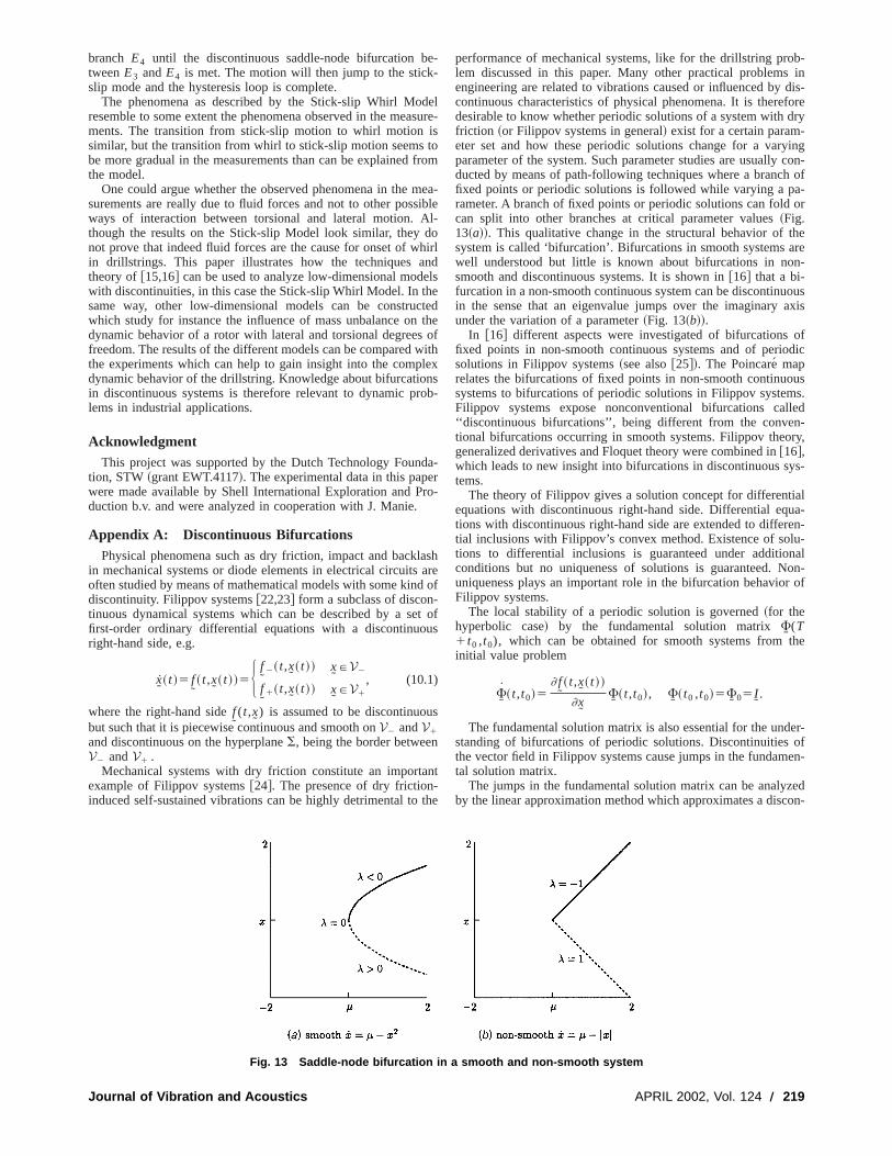
BranchP4 is divided in stable and unstable partsP4a to P4d .BranchP4a is connected toP4b by a Neimark-Sacker bifurcationBranchesP4b , P4c and P4d are connected to each other by twflip bifurcations. The branches with period-doubled periodic sotions and quasi-periodic solutions, which start at these bifurtions, have not been calculated.
A number of discontinuous bifurcations exist on the brancP2 to P6 . BranchP2 is connected toP3 ~Fig. 12! by a discon-tinuous flip bifurcation~the period-doubled branch has not becalculated!. The bifurcation occurs when the periodic solutiotouches the stator,r 5Rc . The discontinuity of the contact forcecauses the discontinuous bifurcation. Similarly, branchP5 is con-nected to branchP6 ~Fig. 12! by a discontinuous fold bifurcationat r 5Rc . BranchP3 ~with stick events! is connected to branchP4~without stick events! by a discontinuous fold bifurcation. Thibifurcation is due to the discontinuity in the dry friction force.
A remarkable bifurcation occurs on the equilibrium branch conecting branchE2b with E3 at r 5Rc ~Fig. 12!. This bifurcationpoint was already encountered in the Whirl Model as a disctinuous saddle-node bifurcation at which the branch turns aro~bifurcation point f in Fig. 6!. In addition, two periodic branches
Fig. 12 Stick-slip Whirl Model, zoom of Fig. 11
218 Õ Vol. 124, APRIL 2002
tem
n-
in
co-
ta-onsi-
ll.
-n
olu-ca-
es
nn
n-
n-und,
P4 andP5 , are connected to the bifurcation point in the Stick-sWhirl Model. This bifurcation point is therefore a combined bfurcation of a saddle-node bifurcation and two Hopf bifurcation
The bifurcation diagrams certainly do not show all periodbranches that exist. Period-doubled branches were not calcubut also other branches may be missing in the bifurcation dgrams.
A note has to be made concerning the chosen numerical vaof the parameters in the Stick-slip Whirl Model. Stiffness amass/inertia parameters are chosen such that the torsional efrequency of the rotor is close to the first torsional eigenfrequeof the drillstring. Similarly, the lateral eigenfrequency of the rotis close to the lateral eigenfrequency of the lowest drill colsection. Damping and friction constants are more or less atrarily chosen. The equilibrium and periodic branches in the bifcation diagrams depend of course on the chosen constants. Hever, the periodic whirl branches,P2 to P6 , seem to be close tothe equilibrium branchE2 . The equilibrium branches form astructure to which the periodic branches are attached. A lot abthe dynamics of this particular system can already be said othe location of the equilibrium branches are known. The vavc , expressed in Eqs.~7.13! and ~7.17!, gives the location ofbranchE2 . The ratiombvmf /c determines whether branchE3proceeds to the right of bifurcation point f or folds to the left~Fig.6!. The valuevd of Eq. ~7.27! gives the starting point of branchE4 . Consequently,vc , vd and mbvmf /c determine the mainstructure of the bifurcation diagram.
10 Discussion and ConclusionsIn the previous sections a simple model was constructed, ba
on the assumption that the fluid forces are the cause of thenomena observed in the measurements. The Stick-slip WModel was analyzed with path-following techniques and bifurction theory presented in@15,16#. What can we conclude from theStick-slip Whirl Model with respect to the measurements?
The Stick-slip Whirl Model exhibits both stick-slip motion anwhirl motion ~which is not possible in the models of Jansen@2#!.Stick-slip motion is prevalent at low angular velocities and baward whirl ~during which the rotor rolls backward over the stato!is prevalent for high angular velocities consistent with the msurements. Stick-slip and whirl motion coexist for an interval ofvboth in the model and in the measurements. Combined stick-whirl motion was not observed in the measurements but wfound in the Stick-slip Whirl Model~branchesP2 andP3!. How-ever, this combined motion occurs only in a very small intervalv in the model. The model is therefore consistent with the msurements in the sense that stick-slip motion occursor whirl mo-tion ~both possible for the same value ofv!, but a combination israre or not existing.
The measurements show a hysteresis effect for a sweesweep-down test~Fig. 4!. The drillstring starts in stick-slip motionat low angular velocity of the rotary table. When the rotary tabspeed is increased with small steps, the motion remains instick-slip mode but at 11.5@rad/s# the drillstring suddenly stops tooperate in the stick-slip mode and starts to whirl backward. Tdrillstring remains whirling for increasing rotary table speed aafter the rotary table speed is diminished in small steps duringsweep-down test. The mean-bending moment~and whirl radius?!drop between 7 and 2@rad/s# and stick-slip recommences.
A similar hysteresis effect can be seen for the Stick-slip WhModel. At low values ofv the rotor is in stick-slip motion. Whenv is increased quasi-statically, branchP1a is followed~Fig. 9! andthe rotor will remain in the stick-slip mode. BranchP1 becomesunstable for increasingv due to the destabilizing fluid forces anthe motion of the rotor will rapidly change via branchesP2 andP3 to an oscillatory whirl motion on branchP4 . Whenv is in-creased even more the motion will jump to regular backwwhirling motion without slip on branchE4 . If v is subsequentlyquasi-statically decreased, the rotor will remain to operate
Transactions of the ASME
-
d
i
m
Ad
e
c
w
nr
l
d-
n
b-in
dis-foredry
yingcon-
h ofa-or
here
n-
ousaxis
ofdic
uss.
lled-ry,
ys-
alua-en-u-nalon-
r of
he
er-ofen-
zedon-
branch E4 until the discontinuous saddle-node bifurcation btweenE3 andE4 is met. The motion will then jump to the stickslip mode and the hysteresis loop is complete.
The phenomena as described by the Stick-slip Whirl Moresemble to some extent the phenomena observed in the meaments. The transition from stick-slip motion to whirl motionsimilar, but the transition from whirl to stick-slip motion seemsbe more gradual in the measurements than can be explainedthe model.
One could argue whether the observed phenomena in thesurements are really due to fluid forces and not to other possways of interaction between torsional and lateral motion.though the results on the Stick-slip Model look similar, theynot prove that indeed fluid forces are the cause for onset of win drillstrings. This paper illustrates how the techniques atheory of@15,16# can be used to analyze low-dimensional modwith discontinuities, in this case the Stick-slip Whirl Model. In thsame way, other low-dimensional models can be construwhich study for instance the influence of mass unbalance ondynamic behavior of a rotor with lateral and torsional degreesfreedom. The results of the different models can be comparedthe experiments which can help to gain insight into the compdynamic behavior of the drillstring. Knowledge about bifurcatioin discontinuous systems is therefore relevant to dynamic plems in industrial applications.
AcknowledgmentThis project was supported by the Dutch Technology Foun
tion, STW~grant EWT.4117!. The experimental data in this papewere made available by Shell International Exploration and Pduction b.v. and were analyzed in cooperation with J. Manie.
Appendix A: Discontinuous BifurcationsPhysical phenomena such as dry friction, impact and back
in mechanical systems or diode elements in electrical circuitsoften studied by means of mathematical models with some kindiscontinuity. Filippov systems@22,23# form a subclass of discontinuous dynamical systems which can be described by a sefirst-order ordinary differential equations with a discontinuoright-hand side, e.g.
x> ~ t !5 f>~ t,x> ~ t !!5H f
>2~ t,x> ~ t !! x>PV2
f>1~ t,x> ~ t !! x>PV1
, (10.1)
where the right-hand sidef>(t,x> ) is assumed to be discontinuou
but such that it is piecewise continuous and smooth onV2 andV1
and discontinuous on the hyperplaneS, being the border betweeV2 andV1 .
Mechanical systems with dry friction constitute an importaexample of Filippov systems@24#. The presence of dry friction-induced self-sustained vibrations can be highly detrimental to
Journal of Vibration and Acoustics
e-
elsure-stofrom
ea-iblel-o
hirlndlsetedtheofith
lexs
ob-
da-rro-
ashareof
t ofus
s
nt
the
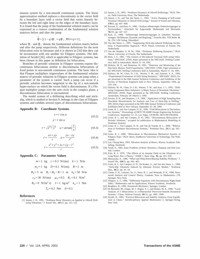
performance of mechanical systems, like for the drillstring prolem discussed in this paper. Many other practical problemsengineering are related to vibrations caused or influenced bycontinuous characteristics of physical phenomena. It is theredesirable to know whether periodic solutions of a system withfriction ~or Filippov systems in general! exist for a certain param-eter set and how these periodic solutions change for a varparameter of the system. Such parameter studies are usuallyducted by means of path-following techniques where a brancfixed points or periodic solutions is followed while varying a prameter. A branch of fixed points or periodic solutions can foldcan split into other branches at critical parameter values~Fig.13~a!!. This qualitative change in the structural behavior of tsystem is called ‘bifurcation’. Bifurcations in smooth systems awell understood but little is known about bifurcations in nosmooth and discontinuous systems. It is shown in@16# that a bi-furcation in a non-smooth continuous system can be discontinuin the sense that an eigenvalue jumps over the imaginaryunder the variation of a parameter~Fig. 13~b!!.
In @16# different aspects were investigated of bifurcationsfixed points in non-smooth continuous systems and of periosolutions in Filippov systems~see also@25#!. The Poincare´ maprelates the bifurcations of fixed points in non-smooth continuosystems to bifurcations of periodic solutions in Filippov systemFilippov systems expose nonconventional bifurcations ca‘‘discontinuous bifurcations’’, being different from the conventional bifurcations occurring in smooth systems. Filippov theogeneralized derivatives and Floquet theory were combined in@16#,which leads to new insight into bifurcations in discontinuous stems.
The theory of Filippov gives a solution concept for differentiequations with discontinuous right-hand side. Differential eqtions with discontinuous right-hand side are extended to differtial inclusions with Filippov’s convex method. Existence of soltions to differential inclusions is guaranteed under additioconditions but no uniqueness of solutions is guaranteed. Nuniqueness plays an important role in the bifurcation behavioFilippov systems.
The local stability of a periodic solution is governed~for thehyperbolic case! by the fundamental solution matrixFI (T1t0 ,t0), which can be obtained for smooth systems from tinitial value problem
FI ~ t,t0!5] f>~ t,x> ~ t !!
]x>FI ~ t,t0!, FI ~ t0 ,t0!5FI 05II.
The fundamental solution matrix is also essential for the undstanding of bifurcations of periodic solutions. Discontinuitiesthe vector field in Filippov systems cause jumps in the fundamtal solution matrix.
The jumps in the fundamental solution matrix can be analyby the linear approximation method which approximates a disc
Fig. 13 Saddle-node bifurcation in a smooth and non-smooth system
APRIL 2002, Vol. 124 Õ 219
r
e
d
,
i
e-
ited,
n in,
ns-
lla-e
.
a-er-
heat
1.4,-
f the, pp.
l-s,’’ce,
ate,’’e and
u-cal.ofof
a-
ofh-
a
J.
98,r
,
d
all
b-
tinuous system by a non-smooth continuous system. The linapproximation method replaces a discontinuity in the vector fiby a boundary layer with a vector field that varies linearly btween the left and right limit on the edges of the boundary layIt is found that the jump of the fundamental solution matrix canexpressed as a convex combination of the fundamental solumatrices before and after the jump
FI 5$~12q!FI 21qFI 1 ,;0<q<1%,
whereFI 2 andFI 1 denote the fundamental solution matrix befoand after the jump respectively. Different definitions for the tebifurcation exist in literature and it is shown in@16# that they canbe inconsistent with one another for Filippov systems. The dnition of Seydel@26#, which is applicable to Filippov systems, habeen chosen in this paper as definition for bifurcation.
Branches of periodic solutions in Filippov systems exposecontinuous bifurcations similar to discontinuous bifurcationsfixed points in non-smooth continuous systems. The basic idethat Floquet multipliers~eigenvalues of the fundamental solutiomatrix! of periodic solutions in Filippov systems can jump whenparameter of the system is varied. Such a jump can occurperiodic solution becomes tangential to the tip of a non-smohyper-surface on which the vector field is discontinuous. If a Fquet multiplier jumps over the unit circle in the complex planediscontinuous bifurcation is encountered.
The model system of a drillstring describing whirl and sticslip, which is studied in Section 9, belongs to the class of Filippsystems and exhibits several types of discontinuous bifurcatio
Appendix B: Coordinate Systems
x5r cosa(10.2)
y5r sina
r 5Ax21y2 a5arctanS y
xD (10.3)
r 5xx1yy
ra5
yx2 xy
r 2 (10.4)
r 5x21 y21 xx1 yy2 r 2
r(10.5)
Appendix C: Parameter Values
m51 kg c50.3 N/~ms) k51 N/m
mf51 kg D50.1 N/~ms) R52 m
Rb53 m Rc5Rb2R51 m kb550 N/m
cb530 N/~ms) mb50.5 B150.1 N/m3
B250 N/~m3 s) J51 kg m2 kw51 Nm
T050.2 Nm d50.3
References@1# Jansen, J. D., 1991, ‘‘Nonlinear Rotor Dynamics as Applied to Oilwell Dr
string Vibrations,’’ J. Sound Vib.,147~1!, pp. 115–135.
220 Õ Vol. 124, APRIL 2002
earelde-er.betion
rem
fi-s
is-ofa isna
if aothlo-a
k-ovns.
ll-
@2# Jansen, J. D., 1993, ‘‘Nonlinear Dynamics of Oilwell Drillstrings,’’ Ph.D. Thsis, Delft University Press, The Netherlands.
@3# Jansen, J. D., and Van den Steen, L., 1995, ‘‘Active Damping of Self-exTorsional Vibrations in Oilwell Drill strings,’’ Journal of Sound and Vibration179~4!, pp. 647–668.
@4# Kreuzer, E., and Kust, O., 1996, ‘‘Analyse selbsterregter DrehschwingungeTorsionsta¨ben,’’ Zeitschrift fur Angewandte Mathematik und Mechanik76~10!, pp. 547–557.
@5# Kust, O., 1998, ‘‘Selbsterregte Drehschwingungen in schlanken Torsiostrangen; Nichtlineare Dynamik und Regelung,’’ Fortschr.-Ber. VDI Reihe11,Nr. 270, VDI Verlag, Dusseldorf.
@6# Van den Steen, L., 1997, ‘‘Suppressing Stick-slip-induced Drillstring Oscitions: A Hyperstability Approach,’’ Ph.D. Thesis, University of Twente, ThNetherlands.
@7# Van der Heijden, G. H. M., 1994, ‘‘Nonlinear Drillstring Dynamics,’’ Ph.DThesis, University of Utrecht, The Netherlands.
@8# Brett, J. F., 1991, ‘‘The Genesis of Bit-induced Torsional Drill string Vibrtions,’’ SPE/IADC 21943, Paper presented at the SPE/IADC Drilling Confence held in Amsterdam, March 11–14, 1991.
@9# Dufeyte, M. P., and Henneuse, H, 1991, ‘‘Detection and Monitoring of tSlip-Stick Motion: Field Experiments,’’ SPE/IADC 21945, Paper presentedthe SPE/IADC Drilling Conference held in Amsterdam, March 11–14, 199
@10# Dykstra, M. W., Chen, D. C-K., Warren, T. M., and Zannoni, S. A., 199‘‘Experimental Evaluations of Drill String Dynamics,’’ SPE/IADC 28323, Paper presented at the 69th Annual Technical Conference and Exhibition oSociety of Petroleum Engineers held in New Orleans, September 1994319–334.
@11# Dykstra, M. W., Chen, D. C-K., Warren, T. M., and Azar, J. J., 1995, ‘‘Drilstring Component Mass Imbalance: A Major Source of Downhole VibrationSPE/IADC 29350, Paper presented at the SPE/IADC Drilling ConferenAmsterdam, February 28–March 2, 1995.
@12# Pavone, D. R., and Desplans, J. P., 1994, ‘‘Application of High Sampling RDownhole Measurements for Analysis and Cure of Stick-Slip in DrillingSPE 28324, Paper presented at the SPE 69th Annual Technical ConferencExhibition held in New Orleans, September 25–28, 1994.
@13# Leine, R. I., and Van Campen, D. H., 1999, ‘‘Fold Bifurcations in Discontinous Systems,’’Proceedings of DETC’99 ASME Design Engineering TechniConferences, September 12–15, Las Vegas, CD-ROM, DETC99/VIB-8034
@14# Leine, R. I., and Van Campen, D. H., 2002, ‘‘Discontinuous BifurcationsPeriodic Solutions,’’ accepted for publication in Mathematical ModellingNonlinear Systems.
@15# Leine, R. I., Van Campen, D. H., and Van de Vrande, B. L., 2000, ‘‘Bifurctions in Nonlinear Discontinuous Systems,’’ Nonlinear Dyn.,23~2!, pp. 105–164.
@16# Leine, R. I., 2000, ‘‘Bifurcations in Discontinuous Mechanical SystemsFilippov-Type,’’ Ph.D. thesis, Eindhoven University of Technology, The Neterlands.
@17# Lee, Chong-Won, 1993,Vibration Analysis of Rotors, Kluwer Academic Pub-lishing, Dordrecht.
@18# Tondl, A., 1965,Some Problems of Rotor Dynamics, Chapman and Hall Lim-ited, London.
@19# Fritz, R. J., 1970, ‘‘The Effects of an Annular Fluid on the Vibrations ofLong Rotor, Part 1-Theory,’’ ASME J. Basic Eng.,92, pp. 923–929.
@20# Muszynska, A., 1986, ‘‘Whirl and Whip-Rotor/Bearing Stability Problems,’’Sound Vib.,110~3!, pp. 443–462.
@21# Leine, R. I., Van Campen, D. H., De Kraker, A., and Van den Steen, L., 19‘‘Stick-Slip Vibrations Induced by Alternate Friction Models,’’ NonlineaDyn., 16~1!, pp. 41–54.
@22# Clarke, F. H., Ledyaev, Yu. S., Stern, R. J., and Wolenski, P. R., 1998,Nons-mooth Analysis and Control Theory, Graduate Texts in Mathematics 178Springer, New-York.
@23# Filippov, A. F., 1988, ‘‘Differential Equations with Discontinuous Right-HanSides,’’ Mathematics and Its Applications, Kluwer Academic, Dordrecht.
@24# Brogliato, B., 1999,Nonsmooth Mechanics, Springer, London.@25# Di Bernardo, M., Feigin, M. I., Hogan, S. J., and Homer, M. E., 1999, ‘‘Loc
Analysis of C-Bifurcations inn-Dimensional Piecewise-Smooth DynamicaSystems,’’ Chaos, Solitons Fractals,10~11!, pp. 1881–1908.
@26# Seydel, R., 1994, ‘‘Practical Bifurcation and Stability Analysis; From Equilirium to Chaos,’’ Interdisciplinary Applied Mathematics 5, Springer-Verlag,New York.
Transactions of the ASME