sticks and tissue no 49 december 2010sticksandtissue.yolasite.com/resources/2010/st49.pdf · sticks...
TRANSCRIPT
1
Sticks and Tissue No 49 – December 2010
I‘d like to thank all the contributors, without whom this newsletter would not be possible.
If you can contribute any articles, wish to make your point of view known etc please send to or phone 01202
625825 [email protected]
Thanks to Mark Venter back issues are available for download from http://www.cmac.net.nz/
Writings and opinions expressed are the opinion of the writer but not necessarily the compiler/publisher of
Sticks and Tissue. The content does not follow any logical order or set out, it‘s ―as I receive and put in‖.
Another great Chistmas card by Mike Cummings of Raynes Park MAC

2
2010 if nothing else will be remembered for those well known aeromodellers who have passed away.
Sadly added to the list is Keith Harris who passed away a few days ago. I personally never knowingly
met him but spoke to him on the phone when ordering plans, his knowledge of which was vast.
Gamma Gull from Mick Butler
Thought you might like to see my latest project. A 100‖ Gamma Gull built from scratch. A nice easy build,
with optional gull or polyhedral wings, and an all moving tail plane. I chose to have the gull wings and just
the simple elevator option. The under carriage is a
removable added extra as I fly mostly at Beaulieu in the
New Forest where we fly off a concrete runway. Covered
with solartex, all up weight is exactly 4 lb. Not flown yet
......
Bill Longley sent these photos in of his latest power duration models for radio assist in 2011.
Bill now has quite a few models and will be running a few comps, more details to follow but if you’re
interested his email is [email protected]

3
CL Sharpoon from
November 1961 Aero
Modeller by Keith
Laumer
(better detail than when
appeared in issue 25)
A 36‖ span aerobatic
trainer for .8 to 1.3 cc
engines (larger sizes can be
used by experienced fliers)
that combines good looks
with simplicity.
THE MODELLER WHO
limits himself to free-flight
is missing half the fun of
modelling; you‘ll discover
what the other half is all
about when you‘ve built
Sharpoon and seen her
performing smoothly at the
end of the lines, responsive
to every touch of the
controls. Control-line
flying gives you the
opportunity to use bigger
engines and long motor
runs and without any
chasing downwind at the
end of the flight. You‘ll
discover that
there‘s more to C/L
piloting than merely
holding onto the handle!
(The Control-line Manual
tells you more.)
Start by cutting out the
plywood bulkheads (parts
FI, F2 and F3). Cut holes
for motor bearers (be sure
to match them to your
engine), and drill undercart
lacing
holes. Bend nose and main
undercarriage legs from 12
S.W.G. wire, and lace in
position with thread; then
coat lacing with cement,
forcing it through holes for
rigidity.

4
Next, cut and drill motor bearers and attach to engine; fit the bearers into bulkheads FI and F2, positioning
carefully, and cement. A polyphenyl resin glue such as LePage‘s white glue (P.V.A.) is recommended for
this use.
Cut the remaining balsa bulkheads, and fuselage sides, and sand edges; add 1/8 x ¼ reinforcing pieces at tail,
and bevel rear ends of sides as shown. Then join sides on motor mount assembly, and align carefully. Add
bulk head F4. When dry, bring rear ends together and hold with spring clothes pegs until dry. Bend and
attach tailskid to F6, and install remaining bulkheads, except F3; this is installed after wing is in place.
Install tank and fuel line; then cut top slabs from
soft 1/4 in balsa and cement in place; cut and add
cowl sides and bottom pieces. (The engine should
be removed for this operation, and holes cut later.
Engine should be reinstalled and spinner fitted
before final shaping, to insure smooth lines). Sand
sides and top of fuselage smooth, and shape as
shown on plan to proper cross-section. Do not sand bottom edge until bottom planking is installed. Cut balsa
tail assembly parts, assemble rudder and tailplane and sand to streamline cross-section. Clear-dope and sand
again; then bend and fit elevator horn/connector, joining elevators. Attach elevators to tailplane with linen
hinges. Bend push-rod, engage in elevator horn, and install tailplane. Be sure to trim away enough of tail
reinforcement to allow free movement of controls.
Add the rudder, aligning it carefully. Note that an off-set tab may be used if desired to increase line tension;
this is advisable if you plan to fly in high winds. Weight may be added to the outboard wing-tip for the same
purpose.
Cut the double wing spar from the straightest, hardest balsa you can find. Coat both pieces with cement and
allow to dry; then re-cement and join under pressure (put the assembly under the work-board and sit on it, if
you can‘t think of a better method). Notch the spar carefully after it is fully dry, allow at least a couple of
hours. Be sure not to cut notches too deep or you will weaken the wing. Cut 18, 3/4 in x 6 in rib blanks, pin
together, and shape all ribs as a unit, using a rib template at each end of the stack. Separate, and bore lead-
out holes in half the ribs, for left panel. Next, cement all ribs to spar, settling in notches so that both top and
bottom surfaces are flush. Add leading-edge reinforcing strip to align ribs; mark positions of ribs on this
strip, using actual spar as guide; this will ensure that ribs are parallel. Cut trailing edge strips from hard
balsa; add lower strip, and, when dry, bevel to follow line of top of rib. Then add top strip, and trim to knife-
edge. Add leading edge and tips, bend and install leadouts,
Then add top and bottom leading-edge planking. Cut slot for front lead-out in centre section. Cut and install
cap strips, and plank upper sides of tips. Use a sanding block to shape the entire wing structure to a smooth
airfoil shape, as shown on side view. Drill a small hole for the bell-crank mounting bolt, and cut slot for F3
and rear lead-out. Install the wing now, and cement thoroughly. Slide bulkhead F3 in place from the bottom,
and add bell-crank, engaging it with lead-outs and push-rod before installing bolt.
Add fuselage bottom planking and sand to shape. Check over
entire structure for rough spots, and touch Up as necessary. Extra
care at this stage will pay dividends in looks and performance
later.
Cover wing with heavyweight Modelspan. For an extra-fine
finish, entire model may be covered; this also adds to strength.
Water shrink the tissue and allow to dry. Then clear-dope and
sand lightly with fine paper. Spray or brush three coats of
pigmented dope over entire model. White is recommended, with
trim in colours to suit individual taste. Mark position of canopy
on top of fuselage, and cut a black paper panel to size and
cement in place, then add canopy. Tape off all of canopy and spray to match fuselage. Add transfer
numerals, colour trim, etc. Spinner may be painted to match trim. Solder wheels in place, and you are ready
for testing.
Try to make your first flights on a calm day, over a smooth surface. Be sure the model balances well
forward. Fuel up with about 2 c.c. in the tank for a fifteen second run; this will be long enough to see how

5
the ship handles, and in case of trouble, it‘s a short flight. Try only modest control movements at first, until
you get the feel of the model. Don‘t try that first loop until you‘re sure!
Larger engines may be installed in SHARPOON for more zip, after the training phase is over.
Vintage Model Plans
TIGER SHARK
The 1938 Victor Stanzel control liner scaled up to 72‖
span resulting in a sleek, fully aerobatic model with a
distinct period flavour. For .40 - .60 2-strokes or .60 -
.75 4-strokes. Rudder, aileron and elevator controls.
PRICE £10 + £2 pp
MERCURY MAGNA
Scaled up to 84‖ fromm the original Mercury kit.
Drawing shows rudder only for radio assist plus
additional sheet for all moving tail and rudder.
Lightweight construction but strong.
Up to .50 4-strokes
PRICE £10 + £2 pp
DRAGONFLY
84‖ span original size. Planked elliptical fuselage.
Original design by Charles Williams published in
Flying Aces March 1938. Reproduced from data in
1960 Aeromodeller.
PRICE £12 + £2 pp

6
COQUETTE
72‖ span scaled up from the
Vic Smeed classic biplane of
30‖ span. Only altered
structurally for R/C. All
moving tail plane, rudder on
underfin. For .50 - .90 4-
stroke.
PRICE 72‖ £12 + £2 pp
51‖ version at £8 + £1.50 pp
CUMULUS
Ben Sherenshaw‘s classic design. Only
modified structurally for R/C. Suitable
for up to .75 4-stroke. Original size 96‖
span. Lightly built model typical of
America in the 30‘s.
PRICE £11 + £2 pp
ISAACS FURY
72‖ span scale model of Home Build
Aircraft designed by Jihn Isaacs. Isaac‘s
design is a 7/10ths scale version of the
Hawker Fury. Plan includes description
and write up of original aircraft. Model
suitable for .90 - .120 4-strokes.
PRICE £15 + £4 pp
FINSIHED UNFLOWN MODEL FOR
SALE PRICE NEGOTIABLE

7
JODEL D9 ―BEBE‖
69‖ span ¼ scale model of the original
―Bebe‖ which was designed in 1946 by
Frenchman Jean Delmontez and M. E.
Joly hence Jodel. The model will fly
on rudder only but plans show
authentic wing tip and aileron profiles.
The original flies with n OS .60 4-
stroke (open valves). See RCM&E
February 1994 Clubman column for
write up and pictures.
PRICE £10 + £3 pp
PHOENIX
Originally a 72‖ span F/F model for 5cc
engines. Redesigned structurally for R/C with
all moving tail. Designed originally by Bob
Woollett. Any good .40 - .48 4-stroke
PRICE £10 + £2 pp
POWAVAN
88‖ span. Scaled from Frog kit. Will climb
vertically on a good .60 4-stroke just like the
original. All moving tail.
PRICE £11 + £2 pp
FROG ―PRINCE‖
Scaled up to 120‖ span for R/C from the original
Frog kit. All moving tail
assembly. Uses brass hinge
as detailed below.
PRICE £14 + £4 pp
8
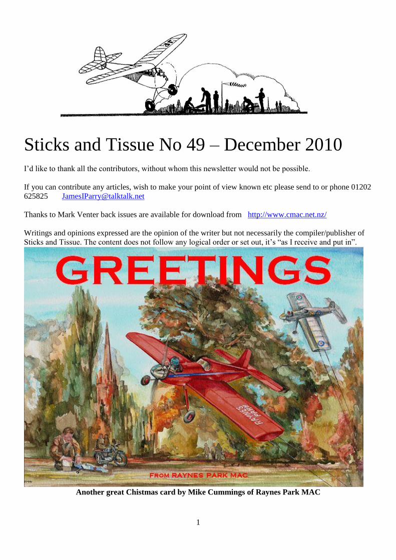
RANGER
Original Megow model kit scaled up to
80‖ span. Redesigned structurally for
R/C. All moving tail, rudder on
underfin. Will accept any 4-stroke for
the engine up to .90 size.
PRICE £11 + £2 pp
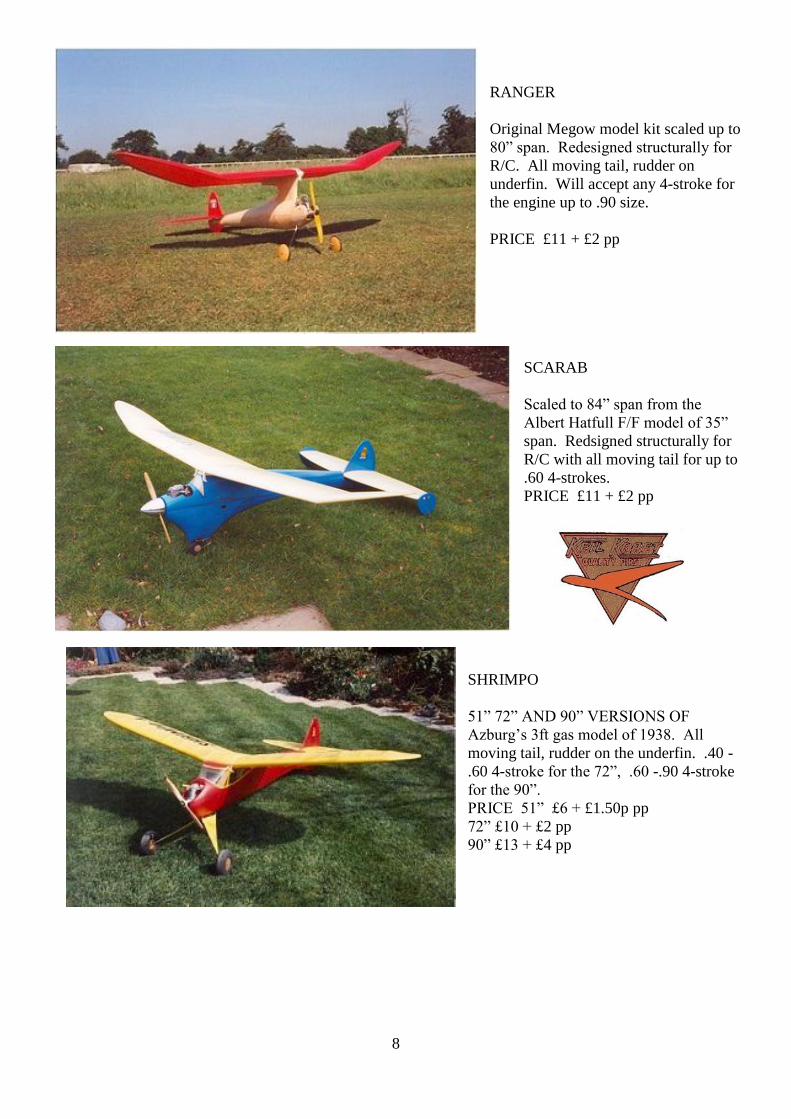
SCARAB
Scaled to 84‖ span from the
Albert Hatfull F/F model of 35‖
span. Redsigned structurally for
R/C with all moving tail for up to
.60 4-strokes.
PRICE £11 + £2 pp
SHRIMPO
51‖ 72‖ AND 90‖ VERSIONS OF
Azburg‘s 3ft gas model of 1938. All
moving tail, rudder on the underfin. .40 -
.60 4-stroke for the 72‖, .60 -.90 4-stroke
for the 90‖.
PRICE 51‖ £6 + £1.50p pp
72‖ £10 + £2 pp
90‖ £13 + £4 pp

9
BIGGER STUFF
Scaled to 85‖ from original classic rubber
model Big Stuff from Col Bowden. Planked
fuselage, elliptical wing and tail. .40 - .60 4-
stroke.
PRICE £12 + £2 pp
GREAT STUFF 120‖ span .60- .90 4-stroke
£13 + £4 pp
Ready built brass tail plane hinge is available for all models in this list with all moving tail assemblies,
complete with nylon screws, fixing screws, and instructions. Can be used on other models if suitable. This
is already detailed on the relevant drawings.
PRICE £8 + £1.50p pp
Plans and mechanisms can be obtained from
PAUL HOWKINS
18 LARKFIELD WAY
COVENTRY
CV5 7QB
TELEPHONE ; 024 76 405126
Transfers shown, and more, are available from Mike Cummings 020 8542 3100 at £1 each. Hurry as not
many left.

10

11
Workmaster by Ron Moulton From July 1962 Aero Modeller
A 48‖ wing span semi-scale model for single channel radio control or sport flying 1 – 1.5 cc.
This MODEL IS no stranger to the locals. The
airframe was built in August 1958 to a
specification laid down at that time for a model
to fill an enormous gap in the plans and kits
available on the British market.
The specification was as follows:- The model
should be of a size to suit most pockets, 1-1.5
c.c. engines; it must look right and fly right; it
must have a specialized structure for its purpose
of single channel radio control. It should be a
weight carrier; have a voluminous interior and be adaptable to a wide range of equipment and engines; it
must be repairable without risk of affecting trim; tough, up to date and practical.
For appearance sake, the near scale approach so well explored by deBolt kits has greatest attractions.
Coincidentally, Austers had just announced in 1958 their hybrid airframe for agricultural purposes with
large tail surfaces, stronger undercarriage and big wheels . . .plus a broad cowling for a horizontally opposed
engine.
This, then, was to be the inspiration, and Workmaster is in most aspects a true 1/9th scale model except for
enlargement of the tailplane, solid windows, simplified undercarriage and lack of struts. Completely new
thought was inspired in fuselage structure. All sheet construction with single creases in sides and base, one
bulkhead and one former make for the easiest possible form of assembly. The volume within the fuselage
under the wing is sufficient to take the most bulky of equipment. Bearers fitted to the fuselage sides, braced
by a ply-former at the front and the replaceable engine mounting plate form ideal vibration dampeners. The
double laminate windshield adds rigidity where wanted and the dowels are so arranged that in a really
serious prang, the wing slides straight off.
Tail surfaces with anti-warp features are fixed after the initial glide tests. Slight adjustment made on the
prototype is incorporated in the design. The wing is made to work. That is to say, airfoil is NACA 4415
sheet surfaced over the working area where it matters, with the result that the Workmaster will lift a loading
of up to 20 oz./sq. ft. without difficulty. The normal operating
loading is about 12-14 oz./sq. ft. Spruce spars and three dihedral
braces have kept the wing together after innumerable cartwheel
landings. Over the centre section, the dummy cabin top lifts to
reveal a space sufficient to allow access for tuning.
The dural undercarriage is simple but in case of difficulty of
supply could be replaced by a built-up 12 s.w.g. wire frame with
sheet filling. Despite many ups and downs, the only damage
suffered to the prototype has been shock tears in the silk covered
wing panels, which will give an idea of the strength of the
structure.
The cabin top has ripped off, and once, when a wing tip caught a fence, the impact as the fuselage swung
round was sufficient to break away a large area of the rear fuselage.
In every respect the Workmaster has more than lived up to its name and met every aspect of its original
specification. It has been subject to all the trials and tribulations of working out best installation for new
equipment and its current gear is still the original Mini-Reptone, Elmic Commander Compound and
F. Rising 4 position clockwork escapement for engine speed. The AM.l5 is most responsive on a 9x4
propeller. Every effort should be made to insulate mechanical rattles. Connections from push rods to
escapements should be covered with Systoflex or thin fuel tubing.
Battery supply to the receiver should be regularly checked. The editor uses 4 DEAC 225 cells to provide 4.8
volts instead of the normal 3 U7 dry batteries. Those who intend to use the same set-up are strongly advised
to study data sheet 12 issued with Radio Control Models & Electronics for September 1961, which covered

12
just about all the possibilities and condensed most valuable information on the Mini Reptone. Full building
instruc tions are quoted on the plan and should be sufficient for the relative novice.
Flying the Workmaster is by no means nerve racking. It performs admirably without radio control, and will
hold a reasonable course although it is no competition model.
Full range of Cox 049 Spares and Control Line accessories stocked, plus many classic kits
from America manufacturer Black Hawk Models
New Cox 049 reed valve engines from £10.50 Control Line Kits from £15.50
On Line shop at www.densmodelsupplies.co.uk Or phone Den on 01983 616603
13
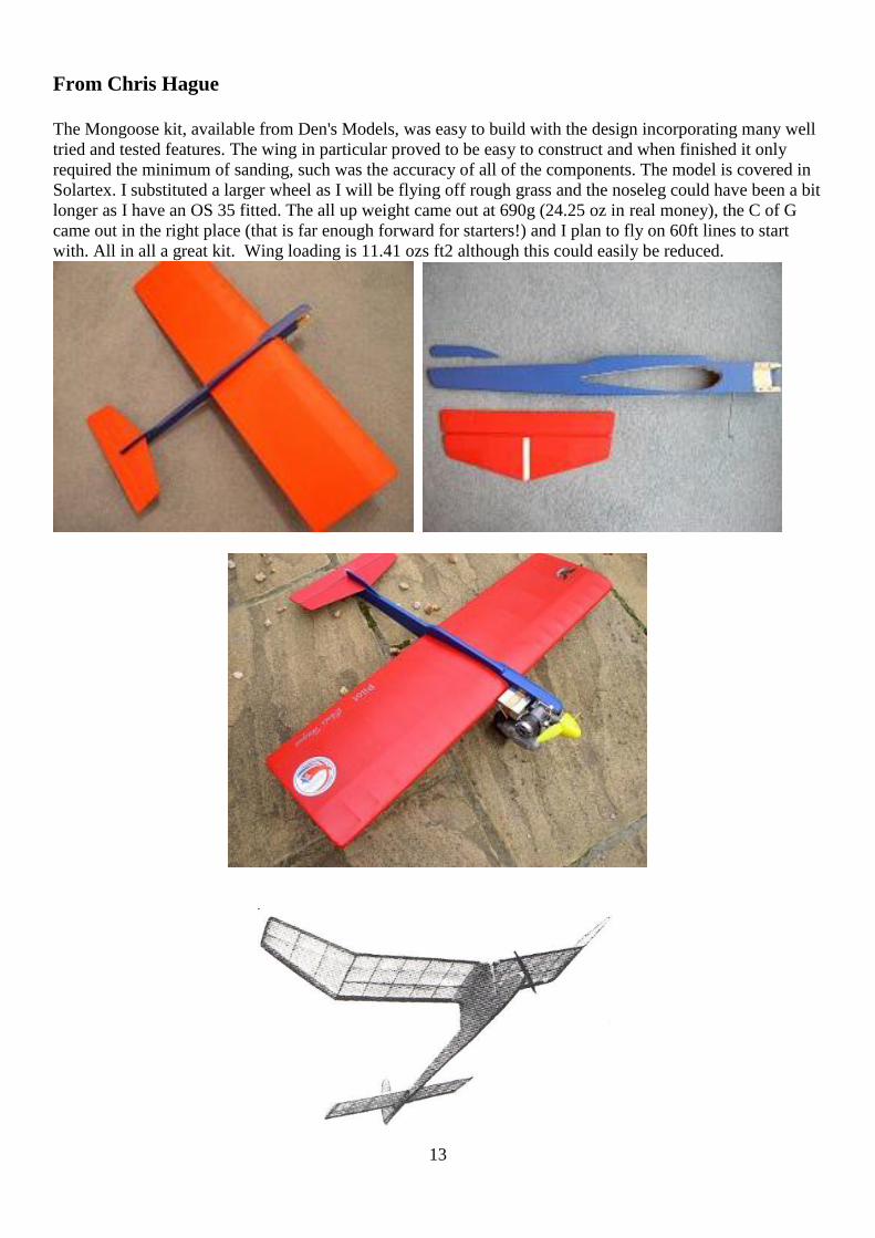
From Chris Hague
The Mongoose kit, available from Den's Models, was easy to build with the design incorporating many well
tried and tested features. The wing in particular proved to be easy to construct and when finished it only
required the minimum of sanding, such was the accuracy of all of the components. The model is covered in
Solartex. I substituted a larger wheel as I will be flying off rough grass and the noseleg could have been a bit
longer as I have an OS 35 fitted. The all up weight came out at 690g (24.25 oz in real money), the C of G
came out in the right place (that is far enough forward for starters!) and I plan to fly on 60ft lines to start
with. All in all a great kit. Wing loading is 11.41 ozs ft2 although this could easily be reduced.
14
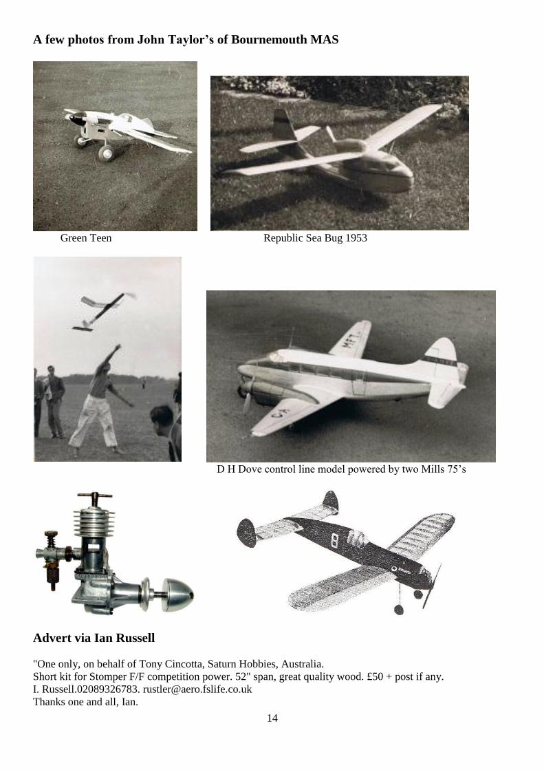
A few photos from John Taylor’s of Bournemouth MAS
Green Teen Republic Sea Bug 1953
D H Dove control line model powered by two Mills 75‘s
Advert via Ian Russell
"One only, on behalf of Tony Cincotta, Saturn Hobbies, Australia.
Short kit for Stomper F/F competition power. 52" span, great quality wood. £50 + post if any.
I. Russell.02089326783. [email protected]
Thanks one and all, Ian.

15
Sadly the last of the Swiss photos kindly sent by Peter Renggli taken by Urs Brandt

16

17
From Roger Cooper
Here is a little "blast from the past". This a genuine original waterslide transfer for the Northwick Park MAC
- must date from the mid 1950's I would guess - Peter Wallis and/or Don Goulding might be able to confirm
that. Now! Is this a valuable relic - a must save piece of memorabilia? I just CANNOT bring myself to
throw it away - it may be the only one left in the world. What do you think, have you an archive for such
things??
From Peter Wallis
I always feel very guilty when I receive Sticks & Tissues so to put that right here are a few photo's taken
around 1952 .
A wonderful performer that I used to fly at Radlett was 'The Eliminator' I still have the Albon Javelin 1.49
that powered this model - together with Roger Cooper we were founder members of 'Northwick Park Model
Aircraft Club' . This picture shows a chap called Stewart, myself and Jack Curry . Jack was my mentor in
18
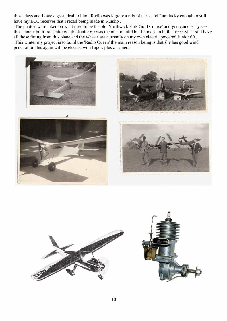
those days and I owe a great deal to him . Radio was largely a mix of parts and I am lucky enough to still
have my ECC receiver that I recall being made in Ruislip .
The photo's were taken on what used to be the old 'Northwick Park Gold Course' and you can clearly see
those home built transmitters - the Junior 60 was the one to build but I choose to build 'free style' I still have
all those fitting from this plane and the wheels are currently on my own electric powered Junior 60 .
This winter my project is to build the 'Radio Queen' the main reason being is that she has good wind
penetration this again will be electric with Lipo's plus a camera.

19
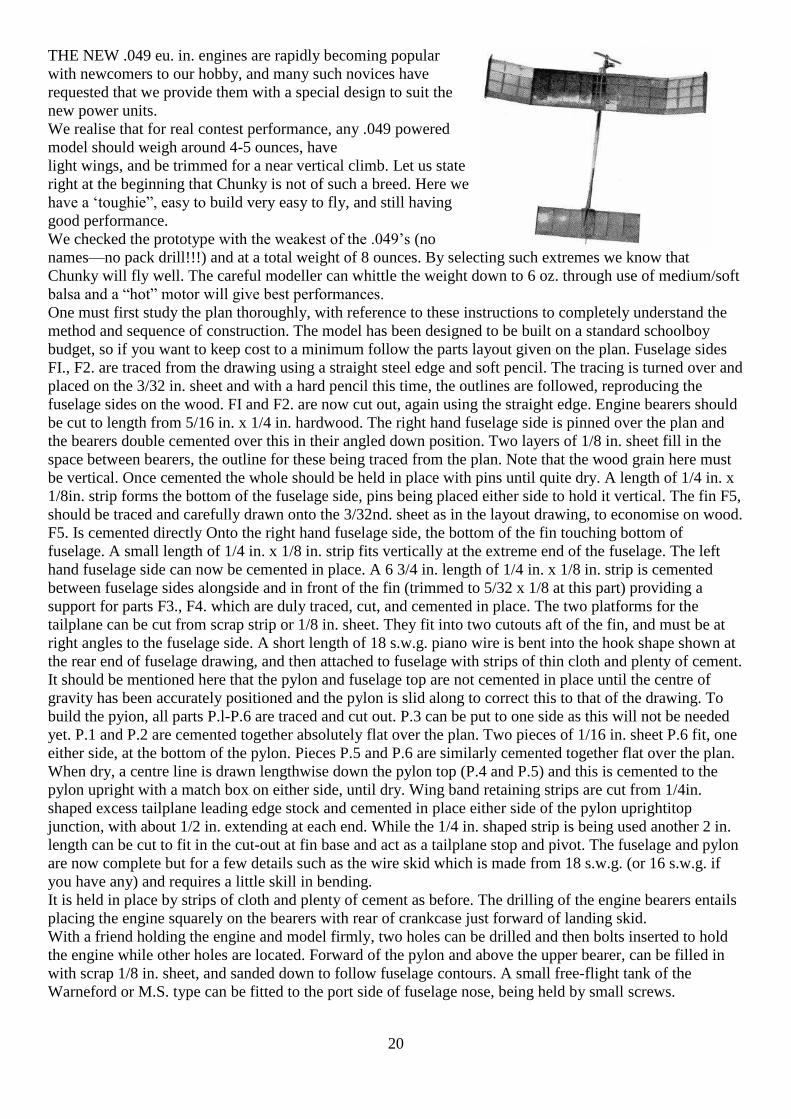
Chunky from Aero Modeller September 1960
20
THE NEW .049 eu. in. engines are rapidly becoming popular
with newcomers to our hobby, and many such novices have
requested that we provide them with a special design to suit the
new power units.
We realise that for real contest performance, any .049 powered
model should weigh around 4-5 ounces, have
light wings, and be trimmed for a near vertical climb. Let us state
right at the beginning that Chunky is not of such a breed. Here we
have a ‗toughie‖, easy to build very easy to fly, and still having
good performance.
We checked the prototype with the weakest of the .049‘s (no
names—no pack drill!!!) and at a total weight of 8 ounces. By selecting such extremes we know that
Chunky will fly well. The careful modeller can whittle the weight down to 6 oz. through use of medium/soft
balsa and a ―hot‖ motor will give best performances.
One must first study the plan thoroughly, with reference to these instructions to completely understand the
method and sequence of construction. The model has been designed to be built on a standard schoolboy
budget, so if you want to keep cost to a minimum follow the parts layout given on the plan. Fuselage sides
FI., F2. are traced from the drawing using a straight steel edge and soft pencil. The tracing is turned over and
placed on the 3/32 in. sheet and with a hard pencil this time, the outlines are followed, reproducing the
fuselage sides on the wood. FI and F2. are now cut out, again using the straight edge. Engine bearers should
be cut to length from 5/16 in. x 1/4 in. hardwood. The right hand fuselage side is pinned over the plan and
the bearers double cemented over this in their angled down position. Two layers of 1/8 in. sheet fill in the
space between bearers, the outline for these being traced from the plan. Note that the wood grain here must
be vertical. Once cemented the whole should be held in place with pins until quite dry. A length of 1/4 in. x
1/8in. strip forms the bottom of the fuselage side, pins being placed either side to hold it vertical. The fin F5,
should be traced and carefully drawn onto the 3/32nd. sheet as in the layout drawing, to economise on wood.
F5. Is cemented directly Onto the right hand fuselage side, the bottom of the fin touching bottom of
fuselage. A small length of 1/4 in. x 1/8 in. strip fits vertically at the extreme end of the fuselage. The left
hand fuselage side can now be cemented in place. A 6 3/4 in. length of 1/4 in. x 1/8 in. strip is cemented
between fuselage sides alongside and in front of the fin (trimmed to 5/32 x 1/8 at this part) providing a
support for parts F3., F4. which are duly traced, cut, and cemented in place. The two platforms for the
tailplane can be cut from scrap strip or 1/8 in. sheet. They fit into two cutouts aft of the fin, and must be at
right angles to the fuselage side. A short length of 18 s.w.g. piano wire is bent into the hook shape shown at
the rear end of fuselage drawing, and then attached to fuselage with strips of thin cloth and plenty of cement.
It should be mentioned here that the pylon and fuselage top are not cemented in place until the centre of
gravity has been accurately positioned and the pylon is slid along to correct this to that of the drawing. To
build the pyion, all parts P.l-P.6 are traced and cut out. P.3 can be put to one side as this will not be needed
yet. P.1 and P.2 are cemented together absolutely flat over the plan. Two pieces of 1/16 in. sheet P.6 fit, one
either side, at the bottom of the pylon. Pieces P.5 and P.6 are similarly cemented together flat over the plan.
When dry, a centre line is drawn lengthwise down the pylon top (P.4 and P.5) and this is cemented to the
pylon upright with a match box on either side, until dry. Wing band retaining strips are cut from 1/4in.
shaped excess tailplane leading edge stock and cemented in place either side of the pylon uprightitop
junction, with about 1/2 in. extending at each end. While the 1/4 in. shaped strip is being used another 2 in.
length can be cut to fit in the cut-out at fin base and act as a tailplane stop and pivot. The fuselage and pylon
are now complete but for a few details such as the wire skid which is made from 18 s.w.g. (or 16 s.w.g. if
you have any) and requires a little skill in bending.
It is held in place by strips of cloth and plenty of cement as before. The drilling of the engine bearers entails
placing the engine squarely on the bearers with rear of crankcase just forward of landing skid.
With a friend holding the engine and model firmly, two holes can be drilled and then bolts inserted to hold
the engine while other holes are located. Forward of the pylon and above the upper bearer, can be filled in
with scrap 1/8 in. sheet, and sanded down to follow fuselage contours. A small free-flight tank of the
Warneford or M.S. type can be fitted to the port side of fuselage nose, being held by small screws.

21
Before commencing wing construction, plywood wing rib templates must be made, three for the main wing.
WI, W2, W3, are traced onto ply and cut out with a sharp modelling knife. The templates are sanded
accurately to correspond with the outlines given on the plan, and are then cut or drawn round, on 1/16 in.
sheet. Eight WI ribs are required, two W2, and six W3. The ribs are cut out, and pinned together as shown in
photo, making sure that bottoms of all ribs are level and the ends are lined up. A short length of 1/4 in. x 1/8
in. strip is placed in the spar slots to keep ribs in position; then with glasspaper wrapped around a block of
balsa or matchbox, abrase to make all ribs identical with each other and one of the ply templates. The pieces
of strip balsa are removed and an 1/8 in. flat file inserted to square up slots.
The 1 in. x 1/4 in. shaped trailing edge strip can now be cut to length for the centre section and notched to
take ten ribs. Shaped 1/2 in. x 1/2 in. leading edge can also be cut to length. Greaseproof or tracing paper
should be laid over the wing plan if it is wished to preserve this.
Leading and trailing edges are pinned down together with a length of 3/8 in. x 1/8 in. strip, in the rear spar
position; note here that both spars are longer than LE/TE and pins are placed either side of spar and not
through. Eight ribs WI. fit over spar and must be vertical; a try-square or matchbox can be used to check
this. Upper 1/4 in. x 1/8 in. spar cements into front slots. When quite dry the structure is removed from plan
to make way for an outer panel. This follows the same procedure of cutting LE‘s, TE‘s and notching the
latter. Spars are again longer than LE/TE to make dihedral joint. LE, TE and rear spar are pinned down and
three W3 ribs cemented in position. Upper spar and two 1/8 in. sheet gussets (to strengthen Outermost rib)
are added. The other wing panel is made in exactly the same way. The Dihedral joints need an explanation
for those not having experience of this type, and are illustrated well in the photo. Innermost ends of the outer
wing panel TEs, LE‘s must first be chamfered to the dihedral angle, a template for which is given on the
plan and can be cut out and pasted onto a piece of sheet balsa. Chamfering is best done with a modelling
knife or razor blade rather than glasspaper, to obtain a flat edge. One of the outer wing panels is mated up to
the centre section at 4 in. dihedral, and the excess spar is carefully trimmed away as shown in photo and
drawing beneath rib outlines on plan. This is repeated for the other panel, and then centre section is pinned
down and outer panels cemented permanently at 4 in. dihedral, using matchboxes to prop up panels. When
completely dry, wing is removed from plan and undersurface between middle two ribs of the centre section
is covered with 1/16 in. sheet; note grain direction.
Tailplane ribs are made in the same way as those of the main wing, except that the template is made from Tl
outline, and there is only one spar slot. Its construction is also the same as that of wing (centre section)
but for the lack of an upper spar. When complete and removed from plan, an 18 s.w.g. wire hook of the type
used on the fuselage is bent and held onto the trailing edge by cloth strips and plenty of cement. Endplate
outlines El, E.2 for wing and taitplane are traced onto 1/16 in. sheet and cut out, there being two off of each.
The dotted lines indicate position of endplates on wing and tailpiane ribs. Note that endplates are not
attached until model has been covered. Before covering any surfaces they must all be lightly smoothed down
with glasspaper.
Covering can be accomplished very quickly by ―wrapping over‖ tissue on all flying surfaces. Lightweight
Modelspan was used on our original model; colours are red centre section/pylon/fln/tailplane, and yellow
fus./wing tipsjendplates, for easy sighting in the air and on ground. Centre section is dealt with first; cut a
piece of tissue that will cover the undersurface and wrap over the uppersurface with a small overlap all
round. The undersurface of the trailing edge is ―Gripflxed‘‘ first and the tissue laid onto this with a 1/8 in.
overlap; if tissue has a dead straight edge, no overlap is necessary. The outermost centre section ribs and the
leading edge are now pasted and tissue pulled down and wrinkles smoothed out. Uppersurface of trailing
edge and outermost ribs are pasted and tissue pulled over and down as shown in photos. Again, wrinkles are
smoothed out with spanwise and chordwise pulls of the overlapping tissue. This overlap is then trimmed
down to 4 in. width and the extreme edge of T.E. pasted. Overlap folds over onto pasted area. Overlapping
tissue at outermost ribs is completely trimmed away. The wing tips and tailplane can be covered in exactly
the same manner as all are parallel chord structures.
Endplate outlines are cut out of tissue 1/8 in. oversize all round and nicked at 1/2 in. intervals, doped directly
onto the endplates. Now fit the endplates in place with cement. Water spray all covering lightly to shrink the
tissue before clear doping.
Fuselage outlines are cut from tissue with similar overlap to that of endplates, and doped on directly. Bottom
of fus, covering does not have overlap, excess if any, being trimmed away with a very sharp razor blade.

22
Each side of pylon can be covered with one piece of tissue, with 1/8 in. overlap at front, back, and top. The
extreme ends of wing rubber band retaining strips are not worth covering due to their odd shape, but brushed
over with sanding sealer, as are the top of pylon platform, tailplane platform and engine bearers. Fin is
covered with two pieces of tissue, and the overlap should be nicked to dope down round the curved outline.
When wing and tail are doped to satisfaction (about 3 coats) and the fuselage, fin and pylon are also
finished, fit the engine and tank, then assemble the model by push fitting the pylon in place. Balance the
model by suspending it on the finger tips at the point indicated as the Centre of Gravity.
Slide the pylon back and forth until the model will balance with the fuselage level. Then mark the pylon
position and dismantle the model so that the pylon can be firmly cemented in place. Now fill the fuselage
top with 1/8 in. x 1/4 in. and fit P.4 tissue cover and dope to finish the model. We used 6 x 4 and 6 x 3 nylon
props to test Chunky and following glide tests which called for no other alterations, made the first test
flight in blustery conditions. The immediate impression is that chunky lives up to its intentions of being an
all-weather flier. It will roll out of trouble, withstand a tumble into the ground or hawthorne bushes (Our‘s is
a rough ground) and with any .049 it will turn right (better) or left depending on your warps and rudder trim.
No claims are made for this design as a Contest winner—but for for the novice wanting to learn how to fly
pylon type models, it‘s the ideal. Moreover, the cost of construction is only 8s. 5d. for all parts including
nuts, bolts and tissue less dope, cement and tank. So for about 13s. (current British prices) plus your engine,
you can get hours of fun flying Chunky on the local field.
Don‘t forget to light the dethermaliser fuse, otherwise you will not see the tailplane tip up, or perhaps the
model, ever again !!!
2011 Preliminary (to be confirmed) dates are now available for Middle Wallop see for further details
http://www.sam1066.org/
All days are free flight with three days noted to also include radio vintage and control line.
February 13
March 20
April 23/24/25 (24 R/C vintage and CL)
May 8 ( R/C vintage and CL)
August 27/28/29 (28 R/C vintage and CL)
September 25
October 23
December 4
Dates for Cocklebarrow will be made known in the New Year
as will many other meets.
There will be R/C vintage at Wimborne but date yet to be agreed due to a busy events year at Cashmoor
however may well be last Sunday in May. There will be CL also at Cashmoor but again dates yet to be
resolved.
With regard to Middle Wallop the RC side is growing, so, much of my efforts will be directed at control
line. So beware I will be going on and on about it over the next few months, you‘d better take advantage of
the non flying conditions and sort out you CL models or build a few new ones!
With regard to Tomboy competitions I‘ve had a few phone calls and emails on the subject and it seems the
numbers wanting to join in are growing. I must point out that there is the ―National‖ Tomboy competitions
run by Tony Tomlin at sites such as Middle Wallop, St Albans, Cocklebarrow, Wimborne etc. The rules
were in the last S&T.
Down in Dorset we run as part of The Wessex League http://www.wessexaml.co.uk/

23
our own version of Tomboy competitions. These events take place relatively locally and the rules do differ
from the ―National‖ competition. The rules for the Wessex League event are set out below for those who
live locally or wish to travel to join in.
We also run a control line speed event which is very basic in order to get competitors who would like to join
in and use what is basically a very simple training model. This is open to anyone. Details on the website.
2011 WESSEX TOMBOY COMPETITION RULES
The event will usually be run with either 1 or 2 qualifying flights of 4 minutes with a fly-off to decide the
overall placings.
1. Each competitor to be a competent pilot and to show proof of BMFA Insurance.
2. Each competitor will require a timekeeper with stopwatch when flying a qualifying round. (Willing
timekeepers often available!) The fly-off timekeeping will be from the starter who will record pilots
names as they land, last one down wins.
3. Hand launch, or ROG, allowed by either competitor or an assistant.
4. Fly-off to consist of a max of 8 pilots, if necessary heats and semi-finals of 8 max pilots to take place
first.
5. For the Fly-off, a total of 90 seconds will be allowed to start the engine with 10 seconds to go a
warning will be given to STOP ADDING FUEL at the end of 90 seconds. Then a HOLD sign will be
displayed, period of time to be notified on the day. Launch when the starter gives the GO signal.
6. No re-starts to be made, or fuel to be added, after the 90 sec.
7. Landing to be in the designated area or zero score.
8. Positions will be calculated for each round as follows; Winner 10 points; 2nd
9; 3rd
8; 4th
7; 5th
6; 6th
5; 7th
4; 8th
3; all others in the fly-off achieving a score of 2 points. Entrants making a flight attempt
but not making the fly-off to receive 1 pt.
9. For overall league placings, the best 4 scores to count. Tie breaks to be decided by highest placings,
if still a tie, then count extra rounds.
10. Models not within the rules to be allowed to compete only at the Contest Director‘s, discretion.
During the season the CD will request an examination of models to check legality. Infringements
will involve a penalty. (e.g. Undersize wheels, 1 minute to be deducted from the fly-off time) You
have been warned!!!!
11. Pilots who have registered a unique 35 MHz frequency with the Contest Directors‘ will be given
total priority on that frequency. Special frequency rules may apply at some sites, please check before
travelling.
12. For various reasons (e.g. safety) these rules may need to be adjusted on the day by the Contest
Director.
13. Return timesheets + entry fee (if required), to the Contest Director, whose decisions are final.
Construction of the model rules are as follows:
WESSEX TOMBOY 36
1. Vic Smeed Tomboy with 36‖ span and small tailplane as per plan. Depending on the plan you use
there are slight variations in size of tail plane therefore we have adopted a maximum span of 423mm
x 110mm chord including elevator.
2. Wing to use bottom spar only. Free choice of spar material.
3. Extra strengthening allowed to the airframe.
4. Any covering material allowed.
5. Pair 2―(50mm) min. diameter x 15mm min. width balloon style wheels to be fitted.
6. 2 or 3 servos to be used for rudder, elevator and optional motor cut-out only. Throttle control not
allowed.

24
7. Engine to be a standard beam mounted MP Jet 040 Classic of 0.6cc with the standard 2cc ali tank.
8. Or standard Mills .75 either original or other replica. Integral fitted fuel tank of 2cc maximum
capacity to be used. (access required to check capacity).
9. Standard, or replica, carburettor only.
10. Engines that have tanks with two holes, one for filling and one for air intake, can extend ONE only
of those holes using fuel tube or metal of nominal bore, maximum length 20mm. Maximun fuel
capacity not to exceed 2cc.
11. Any two bladed propeller to be used. No folding props allowed.
WESSEX TOMBOY Senior 48
1. Vic Smeed Tomboy scaled up by 1/3rd
to 48‖ span.
2. Wing to use bottom spar only. Free choice of spar
material.
3. Extra strengthening allowed.
4. Any covering material allowed.
5. Pair 2.5― min. diameter x 20mm min. width balloon style
wheels to be fitted.
6. 2 or 3 servos to be used for rudder, elevator and optional
motor cut-out only. Throttle control not allowed.
7. Engine to be standard Mills 1.3 either original or replica.
8. Integral fitted fuel tank of 6cc maximum capacity to be
used. (access required to check capacity)
Note: Irvine tank is larger, an aluminium insert is required to reduce capacity to 6cc. (Contact James
Parry if further information is required.)
9. Standard, or replica, carburettor only.
10. Engines that have tanks with two holes, one for filling and one for air intake, can extend ONE only
of those holes using fuel tube or metal of nominal bore, maximum length 20mm. Maximum fuel
capacity not to exceed 6cc.
11. Any two bladed propeller to be used. No folding props allowed.
Helpful notes:
These rules are specifically designed to enable the vast majority of modellers to have fun building and flying a
competitive Tomboy and to minimise the excessive heights that have been achieved in the past. A wide range of
Mills engines can be utilised as well as the MP Jet 040 Classic diesel.
2cc Mills tanks and both new and second hand Mills engines are available from Peter Rose (Tel: 07900 841
550). MP Jet 040 Classic engines are available from Flitehook (02380 861 541). Partial Tomboy kits are
available from the Old School Model Aeroplane Factory (0208 647 1033), Belair etc.
A variety of Mills engines are often available on eBay.
Contact James Parry to receive Wessex Tomboy information and to register your frequency by phone or email,
it will be on a first come first served basis. No 27 MHz permitted. See also our own website for full details:
www.wessexaml.co.uk
Chris Hague/James Parry

25

26
Cessna C-34 by I S Cameron 34” span scale model for .75 – 1 cc. Aero Modeller March
1960
This clean, high wing cabin monoplane by Cessna
has always been regarded by ―old hand‖
aeromodellers as an ideal subject for a flying scale
model, with its well proportioned lines and lack of
struttery. It is therefore, very surprising that among
the many plans which have appeared from time to
time over the last 20 years none are accurate representations of the aeroplane. This model is the result of two
years research and is an accurate replica of the prototype G-AEAI which is shown in the photographs.
Start by building the tailliane over the plan around a card former, cut to the inside shape of the outline.
Using 1/32 in. x 1/8in. balsa strip soaked in water, form the outline using a slow-drying glue. Fit 1/4in. x
1/16in. balsa spar and ribs and when dry, sand to a thin aerofoil section with a flat bottom. Bind hooks of 22
gauge piano wire for the rubber band attachment to fuselage.
Vertical tail surface is made in similar fashion. The wing L.E. is cut from 1/8 in. x 1/4 in. to fit the rib
contours, T.E. is similarly cut from in. sheet balsa notched to receive each rib. Note that the root rib is from
in. sheet and is faced with in. plywood which extends over the balsa L.E. and T.E. sections, covering the
end grain. Cut the tongue from hard 1/8 in. sheet balsa to the outline shown on the plan. Assemble ribs onto
spar, then fit the leading and tail edges and tips cut
from sheet. Slide in the tongue but do not glue yet.
When this basic frame is dry, remove from plan and
sandpaper all over. Cover L.E. top surface with in.
sheet balsa as well as the tip surface. Prop up the tip
1in, for the dihedral, keep the tongue horizontal and
glue this item now: when dry, fit the two stiffening
spars around the tongue and finally sand all over with
fine grade abrasive paper.
Build the opposite wing in this manner.The basic fuselage is built over the plan, make two frames one on top
of the other, joined later with spacers to fit the plan view. Put in gussets and tubes around the undercarriage
attachment and join the nose with F.l. If a beam mounted engine is to be used, slots will have to be cut in F. I
for the hardwood bearers to suit the engine. Using a radial mounted engine, screw direct to the ply interim
former as shown on the plan. The cabin interior is shown in the sketches and should be modelled for realism
but keep the seats, etc., light in weight.
Fit all stringers, hooks, etc., and tailwheel. Cover with
lightweight tissue and give one coat of clear dope.
Finish all over with Cellon light metallic green with
lettering and trim in dark metallic green. Wing
registration letters are 31/4 in. high x 3/8 in. stroke
width. Those on the fuselage are 1 in. high x 1/8 in.
stroke width. The proportions and positioning of the
letters can be seen from the photographs.
The cowling may be made from fibreglass or balsa with
plastic or balsa ―blisters‖ of which there are 14.
It is held in place on the original by an elastic retaining band between a hook on the front former and a hook
inside the cowl, which itself is located bý small wood blocks. Trim for right circuits and stand by for super
realism!
27
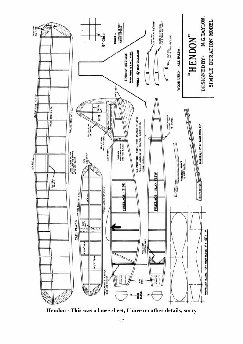
Hendon - This was a loose sheet, I have no other details, sorry

28
David Kinsella’s Column
So Many Gathered
Good sticks stood shoulder to shoulder to honour the great chief. Within ancient stones and lofty beams,
later in a garden marquee where the press of people was considerable, modellers and enthusiasts
remembered Ronald Godfrey Moulton (1924—2010). The service in St James Church, Bushey, was
traditional and perfect, the hymns and Lord‘s Prayer unchanged, the ending light hearted to the sounds of
Let‘s Go Fly a Kite. I was with Vic and Margaret Smeed early on, then SAM 35‘s Brian Lever, AMI‘s
editor Steve Dorling, Dave Bishop of DB Sound and the McHard family. West Essex, Raynes Park, Three
Kings and several more clubs were represented. Dinah, Chris and Jonathan, Ron‘s daughters and son,
arranged the day to perfection, yours truly departing with Mr & Mrs David Rawlins of Flying Toys at 7pm.
Ron Moulton bas gone yet he will be with us always.
Sweet Dream
Man of many abilities Jim Shelley drew and then built a cabin sports job of 65in
span called Mabel‘s Dream, a looker from any angle and a super lady of the skies
whenever she took flight. Jim soon realised that a much larger Mable would be
better and so a delight in green and white duly appeared,
this time of 11ft span and driven by an 0K 20cc twin. Hollow ribs and a thinner
lightweight wing meant struts for strength, as seen here and held aloft by brother
Terry Burton Shelley. Also of abilities various ranging from blasting a BSA Gold
Star around the Island in the Senior
Clubman TT to playing a mighty Wurlitzer
in Brum, Terry restored to mint condition a
1924 Model T — black, of course, as Henry
declared. With that huge spread of wings, the beautiful cabin and
those classical spats from the age of Astaire and Style, an extra shot is
a pleasure and a duty.
John‘s Movies
Throughout the long MEE at Wembley — nine whole wonderful days and late opening on Thursday until
9pm — John Huntley was there with his stock of movies. Utterly perfect for the job, a preamble from the
stage would be followed by the immortal words: ―And now on the screen….‖, and we‘d be away and soon
lost in the golden age of the GWR or Hendon at its zenith. Never an empty seat at Wembley, it was the
same at shows in Croydon and elsewhere, his dedicated public filling the foyer with the buzz of
expectation. But old Wembley was best, the movies a chance to take the weight off after pounding the vast
halls that held the MEE in full bloom. And, of course, the twin towers of Wembley reminded us that it was
the centre of the British Empire Exhibition of 1924, so successful that it was held, again in 1925.
That Driver!
Towers seen on telly and known as Downton Abbey in reality are those of Highclere Castle, erected on an
ancient site by Charles Barry, architect of the Houses of Parliament. A healthy 5000 rolling acres, cedars
grown from imported seeds, a Victorian Gothic saloon three floors high and
further acres of priceless oils and wallpaper show how the upper crust did
things before a stand-in driver lost his way and caused World War One! An
amazing detail of the old days emerged in the shape of a giant wine cooler
commissioned by Lord Raby, of solid silver and the size of a bath. At a recent
sale I saw matched mirrors 11ft high. Out of sight servants tunnels
powerfully affected H G Wells, his mother forced to use them. Not sure about
that ice in the scotch!

29
The Right Stuff
This year I chose Prontoprint (0207 911 0172) to produce my Christmas cards, top quality being essential.
Graham and chums can do anything on the most impressive machinery I‘ve seen. So come on the Northern
to the world of Amy Winehouse and see the boys at 60 Camden High Street when a top notch result is the
issue. Perfect for Aeromodeller covers to frame.
Pistols Preferred
Forget the dainty swordplay in Scaramouche (1952 118 min ), Flynn did it with a grin, Rathbone with a
smirk and a dirk, but rapiers in the mist of Hyde Park one November morning saw Lords Hamilton and
Mohun (say moon.) fight to the death, bites included, all over the estates of Lord Macclesfield. Illegal in
1711 and Hamilton Scotland‘s leading Duke, the two still battled it out and gave rise to numerous Duke of
Hamilton pubs. Pistols normally kept the two apart and sometimes both missed with intention. But it was
risky if one faced a fellow who was not a good stick as in Kubrick‘s Barry Lyndon (1975 187 min ) where
young Lord Bullingdon demands a second shot!
Street Fighter
From the world of newsprint young Harbourne Mackay Stephen of the RAFVR (possibly with a red lining
to his tunic) shot down eight during one sortie and received a Christmas card and £100 from Lord
Beaverbrook (a staggering sum seventy years ago). Soon with a double DFC and a DSO, later a CBE, he
was a high flyer and bagged a bandit at a record 34,000ft. Refusing a big rank hike at the end of the war,
Fleet Street benefited from Stephen‘s drive on the Standard, Express, Telegraph and Times. As a famous ace
once told me, after daily combat against the best anything was easy.
Cabinet Stuff
Modellers King & Country offer a number of 1:30 scale hand-painted figures of
pilots and other RAF types. All-metal too, support buildings such as Nissen huts
are available in cast and painted resin. Try 0800 297 1940. A call to 01388 818882
will give you Waterloo stuff.
Super SE5a
Trailing smoke to port an Albatros (only one s) slips above McCudden‘s famous fighter, B48916 and the
most successful of its type. Of great size was the red spinner which, with
special high compression pistons fitted by his mechanics of elite 56 Squadron,
gave McCudden an extra 4mph. A mighty
scrapper and just 22 when he died, the ace of 57 victories would take on several
on his own and knock down two or three. With his dog Bruiser (rather apt) for
company this most decorated ace of the RFC, RNAS and RAF in World War
One operated from many airfields, the famous 56 disbanding at Bircham
Newton on 22 January 1920. Again fine action stuff from Roger Middlebrook.
R&B And A GL!
Crashing my way through the Christmas card list (I send 200 or so) I suddenly remembered aeromodelling
chum Trevor Robinson, a keen enthusiast who bought balsa from Harry in Gorden Street, Luton (where my
first ETA 29 appeared), and campaigned R&B music from across the pond. Indeed, during office hours he
taught me Roll Over Beethoven and other classics, Chuck B a hero along with Route 66 and the rest of it.
Massively impressive was Trevor‘s transport — a unique—to-me Goliath Luxus! I repaired the radiator with
a silvery mixture and aboard the GL we‘d roar around Bedfordshire
pretending we were Stirling and Jenks in the 1955 Mille Miglia. I still have the first Stones LP Trevor gave
me 43 years ago.
Imperial Inspiration
In Kensington for the Lehman sale I was treated to a sight of the newly discovered Roman helmet, grey-
green, of great age and almost perfect. Just one of three or four dug up and a stunning relic of Rome‘s

30
occupation when we wore skins and rough cloth, selling at £2.28 million and seven times estimate
underscores the importance of quality and rarity.
Top Dollar
At the Raynes Park MAC monthly gathering a while ago I mentioned to Geoff that my soft spot for LNER
engines remained, Gresley adventerous with Main line designs that at times amazed - battleship grey Hush
Hush with marine boiler a case in point. The big P2 fast freight locos for the hilly north
such as Cock O‘ The North turned heads too, one in model form from Germany selling for £12,000 plus
premium. A stiff price for a Gauge O model of 16m or so, in lined apple green she looked the business.
Rod‘s Railway
Following Captain Milani‘s dictum to build big — and members of the LMA certainly do — the model
railway world has done likewise for many years. Measuring 124ft x.23ft and set in the USA of the mid
1940‘s, Rod Stewart CBE has built a magnificent HO gauge layout featuring city skyscrapers and vast
stockyards, busy streets and harbour area, an ethylene plant all of 5ft x 6ft! Steam outline runs with mighty
diesel, endless freight trains at scale speed taking 30 minutes to complete a circuit. ―Every person
should have one hobby that really captures his interest‖, says Rod. His mighty four-decade career includes
the sale of almost 300 million albums. Inspired by the New York Central and Pennsylvania railways, this
stunning layout is now in its sixteenth year. Towerjng stuff!
Intro From Ron
The FAST Club in at the start of things, the name known to many, here we have the shakers and movers
with their models. All smiles in their FAST sweatshirts, Granger
Williams, Rudy Panko, Keith Storey and Howard Borden are there
plus chums and some fifteen models that look
like proper racer aeroplanes. From sixty years
ago, are one or two murmuring carpe diem? A
fine start to a great read on prop stuff full size
and model, Gordon James Rae explores over
260 big pages the history of a subject dear to our hearts
in Aircraft Speed & Vintage Team Racing. Masses of info within hard covers at just
£20 plus postage. Try Traplet on 01684 588500. Ron Moulton‘s Foreword sets the
scene and Gordon‘s sketches and drawings are a treat throughout. Perfect for VTR
reference.
Pier Pressure
Walkways into deep waters was just one of the good things the Victorians did for us. Like being at sea but
without the rocking, the far end held a building, even a lifeboat station, often a landing point for the big
paddle steamers that came down from or went up to Tower Bridge and the famous Pool beyond. Southend
had the longest and Brighton had two, one the setting for Littlewood‘s star—studded Oh! What a Lovely
War (1969 144 mm). A few were cut in two as a safety measure during the war, some sported a railway and
these days there are, support groups to get them going again.
Kids Conkers
Great editor C P Scott of the then Manchester Guardian was told over lunch that there was a shortage of
acetone. The 1914—18 war was on and the boffin facing the newsman was worried. Later dining with Lloyd
George, the Welsh wizard said that acetone shortages were affecting his battleships. In London in a trice the
boffin said that he required a defunct gin distillery and tons of conkers. Children were told to put their
conker in collecting sacks, games forbidden. As the guns fired again a knighthood was offered.
The boffin said that a letter would do, this to advance his political beliefs. Acetone is used in the
manufacture of cordite.
31
Rockfist Rogan
Artwork from those who knew their onions, great yarns from Air Ace Picture
Library launched in 1960 and sold furiously to lads inspired by the deeds of
Fighter and Bomber Command, Coastal Command and the Fleet Air Arm. At
about the same time were Battler Britain and chums, the traditions of boxer and
pilot Rockfist Rogan maintained. Air Aces gives us a 2in wedge—of high action
adventure, chaps with pints and fags, top buttons undone and ready to swat the
Stukas. Detail is impressive, one or two artists having ‗got some in‘. One of the
best served in the Afrikakorps.
Long Term Raçer
I was sorry to hear from Chas Taylor that Gordon Yeldham had died. As far back as I can remember, even to
Belfairs MAC days of the early 1950s, Gordon was active with Oliver,ETA and McCoy—powered control
liners. I was a beardless twerp at the time and massively impressed when a Class A Voodoo leapt from the
grass and put in endless laps trailing light blue smoke and inspiring sounds. Belfairs put on a show in a
church hall one year and there was Gordon‘s McCoy 60 Speed job (the Series 20 was massive to me) plus a
Stomper or two, a Wakefield in red Modelspan and a light green Monitor powered by a BB Amco. Gordon
flew models for sixty years and was known to all in Vintage Team Racing.
Wills And Wishes
Long term your desires may fade in the hands of others. Poet Larkin‘s detailed diaries vanished in the
shredder and one famous modeller‘s engine collection went off to the tip (brief pause to recover from the
shock). One way out is to observe that Carpe Diem sign above the workshop door and pile up as much stuff
as possible. When they come, just hide behind it and you won‘t have to go.
Mighty Mick
On 19 April 1917 Mannnock was in a vertical training dive in his SE5a when the
lower starboard wing peeled away at 700ft. Mick cool in his diary entry, Sergeant
W Bovett in charge of the riggers blanched, his face ―forty below zero‖ as he
approached the SE. Mannock waved to a faulty strut socket and laughed. Unlike
the Camel and others the SE5a had four sets of flying wires to the upper wings, the
ace still managing a good landing in a ploughed field close to his 74 Squadron. At
6pm he was driven to St Omer to collect a new machine, flying back in 8 minutes.
Over the Lines next morning! Units on both sides moved often, shared airfields and
on forward stations were within a mile or two of the trenches, hence moonlight flits!
Advanced Admiral
Edward V111‘s Coronation Review at Spithead in 1937 was a grand affair, ships invited from far and wide.
Causing a stir was the brand new Kriegmarine‘s Admiral Graf Spee. Completed a year earlier, diesel
powered for quick start-up and armed with11in guns, Graf Spee caused chatter over gins in several
wardrooms. Welded to save weight and with space-saving engines, the Panzerschiffe was a good answer to
the speed, guns and armour problem. But the hot radial of her Arado spotter did not like cold water landings.
For a while and using a large model, the sinking of Graf Spee was acted out on a pond in Scarborough while
the dads of amused children attended the Union Conference.
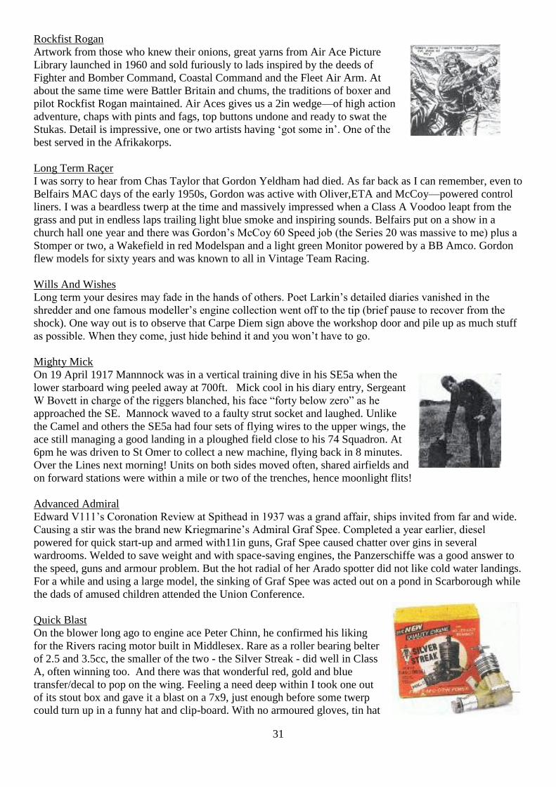
Quick Blast
On the blower long ago to engine ace Peter Chinn, he confirmed his liking
for the Rivers racing motor built in Middlesex. Rare as a roller bearing belter
of 2.5 and 3.5cc, the smaller of the two - the Silver Streak - did well in Class
A, often winning too. And there was that wonderful red, gold and blue
transfer/decal to pop on the wing. Feeling a need deep within I took one out
of its stout box and gave it a blast on a 7x9, just enough before some twerp
could turn up in a funny hat and clip-board. With no armoured gloves, tin hat
32
and breast plate, I‘d be on my way to the slammer!
Airships!
Attended a memorable lecture on the mighty R101 airship. Every seat soon taken to hear Peter Davison and
Giles Camplin and soak up the movies and stills. Staggering was a colour clip of the 800ft supership gliding
above the greenery of Bedford. Peter wrote a spiffing piece in Aeroplane Monthly (7 pages November issue)
and the PhD held by Giles was brought to bear on aspects of big airship operation. Written material at a
discount was quite irresistible. Longer than Canary Wharf is tall, oafs declared that R101 and R100 flew far
too low. Nonsense! They were at their usual I800ft but were so big that the great unwashed thought them
low and a threat to their chimney pots. Time for a great book on these intended Empire linkers, Giles and
Peter are the boys to do it. Haying been to the top of the Cardington sheds when in MOD service, I gripped
the rail when I stared down at the distant floor...These airships were truly massive. The lecture was too.
At Raynes Park MAC
Arriving early I often enjoy a good movie, in November leads of Lancasters and Dirk Bogarde in
Appointment In London (1953). Barry brought along an ETA 29 hardly run and a Keil Kraft Handbook as
pictured in October, published when Eddie was at 195 Hackney Road, London E2. Tom mentioned that his
Dad had built a 3 1/2in Gauge Lord Nelson express engine of the Southern Railway, one of the
4-cylinder locos I‘ve often admired. A topic at my end of the room was the astonishing performance of
Speed engines, running at 45,000rpm and more. There was much talk about Ron Moulton, his picture taken
at Old Warden in 2005 in pride of place an. the wall. A good evening as always.
1911 And All That
Aeroplane Monthly (100 pages packed with colour) has pre Great War roots. Good stuff for the Scale buff,
restorations and new-builds feature strongly and recently a Fighter Factory FW190 in all its glory. What‘s
on and book reviews, features and history from an expert team make it a mus-read. A
healthy stack at Smiths, back issues are from 0203 148 4327.
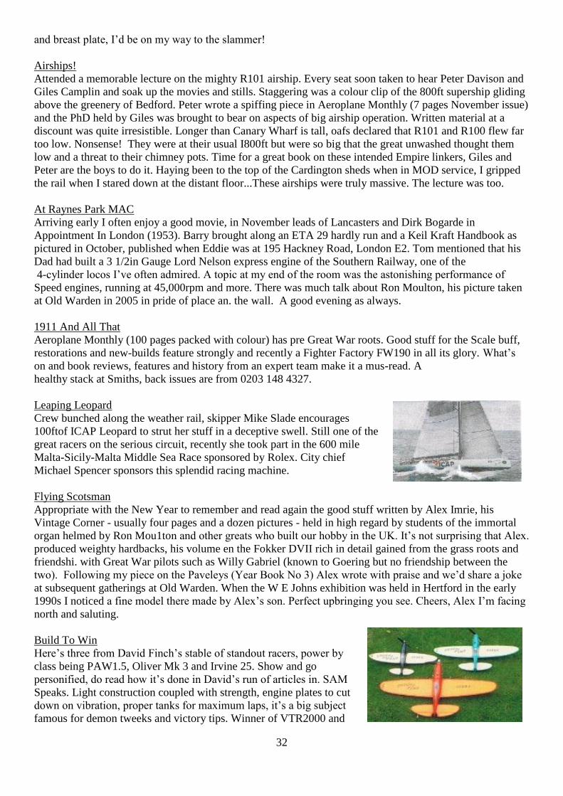
Leaping Leopard
Crew bunched along the weather rail, skipper Mike Slade encourages
100ftof ICAP Leopard to strut her stuff in a deceptive swell. Still one of the
great racers on the serious circuit, recently she took part in the 600 mile
Malta-Sicily-Malta Middle Sea Race sponsored by Rolex. City chief
Michael Spencer sponsors this splendid racing machine.
Flying Scotsman
Appropriate with the New Year to remember and read again the good stuff written by Alex Imrie, his
Vintage Corner - usually four pages and a dozen pictures - held in high regard by students of the immortal
organ helmed by Ron Mou1ton and other greats who built our hobby in the UK. It‘s not surprising that Alex.
produced weighty hardbacks, his volume en the Fokker DVII rich in detail gained from the grass roots and
friendshi. with Great War pilots such as Willy Gabriel (known to Goering but no friendship between the
two). Following my piece on the Paveleys (Year Book No 3) Alex wrote with praise and we‘d share a joke
at subsequent gatherings at Old Warden. When the W E Johns exhibition was held in Hertford in the early
1990s I noticed a fine model there made by Alex‘s son. Perfect upbringing you see. Cheers, Alex I‘m facing
north and saluting.
Build To Win
Here‘s three from David Finch‘s stable of standout racers, power by
class being PAW1.5, Oliver Mk 3 and Irvine 25. Show and go
personified, do read how it‘s done in David‘s run of articles in. SAM
Speaks. Light construction coupled with strength, engine plates to cut
down on vibration, proper tanks for maximum laps, it‘s a big subject
famous for demon tweeks and victory tips. Winner of VTR2000 and

33
VTRSIG President, David is the man to show us how it‘s done. Next month‘s column will feature David‘s
Wharfedale 1000 winner posed with the historic shield. Irvine 25 powered and finished in orange and red,
it‘s a beauty. Tension caused by the interval may be eased by taking the occasional cold bath.
The Special will be ready in a few days. I’ve not decided on best way to send. The preference was to
find a file drop site / FTS etc for single use and unlimited number of downloads, whilst there are free
to use sites the problem is the number of expected downloads which would put the whole thing into a
commercial status. And as you know I don’t like spending out. It may end up as emailing approx 5
files so please if you do not want to receive what will be around 238 engine photos please let me know.
THE END