stm32cubef1 nucleo demonstration firmware - st.com · docid027336 rev 1 3/19 um1853 list of tables...
TRANSCRIPT
February 2015 DocID027336 Rev 1 1/19
UM1853User manual
STM32CubeF1 Nucleo demonstration firmware
Introduction
STMCube™ initiative was originated by STMicroelectronics to ease developers’ life by reducing development efforts, time and cost. STM32Cube covers STM32 portfolio.
STM32Cube Version 1.x includes:
• The STM32CubeMX, a graphical software configuration tool that allows to generate C initialization code using graphical wizards.
• A comprehensive embedded software platform, delivered per series (such as STM32CubeF1 for STM32F1 series)
– The STM32CubeF1 HAL, an STM32 abstraction layer embedded software, ensuring maximized portability across STM32 portfolio
– A consistent set of middleware components such as RTOS, USB, TCP/IP, FatFS and Graphics
– All embedded software utilities coming with a full set of examples.
The STM32CubeF1 Nucleo Demonstration platform is built around the STM32Cube HAL, BSP and FatFs middleware component and uses almost the whole STM32 capability to load and display full color bitmaps from a microSD card.
www.st.com

Contents UM1853
2/19 DocID027336 Rev 1
Contents
1 STM32CubeF1 main features . . . . . . . . . . . . . . . . . . . . . . . . . . . . . . . . . . 5
2 Getting started with the demonstration . . . . . . . . . . . . . . . . . . . . . . . . . 6
2.1 Hardware requirements . . . . . . . . . . . . . . . . . . . . . . . . . . . . . . . . . . . . . . . 6
2.1.1 STM32F103 Nucleo board . . . . . . . . . . . . . . . . . . . . . . . . . . . . . . . . . . . . 6
2.1.2 Adafruit TFT shield . . . . . . . . . . . . . . . . . . . . . . . . . . . . . . . . . . . . . . . . . 7
2.2 Hardware configuration . . . . . . . . . . . . . . . . . . . . . . . . . . . . . . . . . . . . . . . 8
2.2.1 STM32 Nucleo board configuration . . . . . . . . . . . . . . . . . . . . . . . . . . . . . 8
2.2.2 Assembling the Adafruit shield . . . . . . . . . . . . . . . . . . . . . . . . . . . . . . . . 9
3 Demonstration firmware package . . . . . . . . . . . . . . . . . . . . . . . . . . . . . 10
3.1 Demonstration repository . . . . . . . . . . . . . . . . . . . . . . . . . . . . . . . . . . . . . 10
3.2 Nucleo board BSP . . . . . . . . . . . . . . . . . . . . . . . . . . . . . . . . . . . . . . . . . . .11
3.2.1 Joystick . . . . . . . . . . . . . . . . . . . . . . . . . . . . . . . . . . . . . . . . . . . . . . . . . 11
3.2.2 LCD . . . . . . . . . . . . . . . . . . . . . . . . . . . . . . . . . . . . . . . . . . . . . . . . . . . . 12
3.2.3 MicroSD . . . . . . . . . . . . . . . . . . . . . . . . . . . . . . . . . . . . . . . . . . . . . . . . . 12
4 Demo functional description . . . . . . . . . . . . . . . . . . . . . . . . . . . . . . . . . 13
4.1 Programming firmware application . . . . . . . . . . . . . . . . . . . . . . . . . . . . . . 16
5 FAQs . . . . . . . . . . . . . . . . . . . . . . . . . . . . . . . . . . . . . . . . . . . . . . . . . . . . . 17
6 Revision history . . . . . . . . . . . . . . . . . . . . . . . . . . . . . . . . . . . . . . . . . . . 18

DocID027336 Rev 1 3/19
UM1853 List of tables
3
List of tables
Table 1. Bitmap image properties. . . . . . . . . . . . . . . . . . . . . . . . . . . . . . . . . . . . . . . . . . . . . . . . . . . 13Table 2. Document revision history . . . . . . . . . . . . . . . . . . . . . . . . . . . . . . . . . . . . . . . . . . . . . . . . . 18
List of figures UM1853
4/19 DocID027336 Rev 1
List of figures
Figure 1. STM32Cube block diagram . . . . . . . . . . . . . . . . . . . . . . . . . . . . . . . . . . . . . . . . . . . . . . . . . 5Figure 2. STM32F103 Nucleo board . . . . . . . . . . . . . . . . . . . . . . . . . . . . . . . . . . . . . . . . . . . . . . . . . . 7Figure 3. Adafruit 1.8” TFT shield . . . . . . . . . . . . . . . . . . . . . . . . . . . . . . . . . . . . . . . . . . . . . . . . . . . . 8Figure 4. Assembling the Adafruit 1.8” TFT shield. . . . . . . . . . . . . . . . . . . . . . . . . . . . . . . . . . . . . . . . 9Figure 5. Folder structure. . . . . . . . . . . . . . . . . . . . . . . . . . . . . . . . . . . . . . . . . . . . . . . . . . . . . . . . . . 10Figure 6. Nucleo BSP architecture. . . . . . . . . . . . . . . . . . . . . . . . . . . . . . . . . . . . . . . . . . . . . . . . . . . 11Figure 7. Demonstration application menu . . . . . . . . . . . . . . . . . . . . . . . . . . . . . . . . . . . . . . . . . . . . 13Figure 8. Reading the Adafruit shield Joystick . . . . . . . . . . . . . . . . . . . . . . . . . . . . . . . . . . . . . . . . . . 14Figure 9. Demonstration application error messages . . . . . . . . . . . . . . . . . . . . . . . . . . . . . . . . . . . . 15Figure 10. Demonstration running . . . . . . . . . . . . . . . . . . . . . . . . . . . . . . . . . . . . . . . . . . . . . . . . . . . . 15

DocID027336 Rev 1 5/19
UM1853 STM32CubeF1 main features
18
1 STM32CubeF1 main features
STM32CubeF1 gathers, in a single package, all the generic embedded software components required to develop an application on STM32F1 microcontrollers. In line with the STMCube™ initiative, this set of components is highly portable, not only within STM32F1 series but also to other STM32 series.
STM32CubeF1 is fully compatible with STM32CubeMX code generator that allows to generate initialization code. The package includes a low-level hardware abstraction layer (HAL) that covers the microcontroller hardware, together with an extensive set of examples running on STMicroelectronics boards. The HAL is available in open-source BSD license for user convenience.
STM32CubeF1 package also contains a set of middleware components with the corresponding examples. They come in free user-friendly license terms:
• Full USB Host and Device stack supporting many classes.
– Host Classes: HID, MSC, CDC, Audio, MTP
– Device Classes: HID, MSC, CDC, Audio, DFU.
• STemWin, a professional graphical stack solution available in binary format and based on STMicroelectronics partner solution SEGGER emWin
• CMSIS-RTOS implementation with FreeRTOS open source solution
• FAT File system based on open source FatFS solution
• TCP/IP stack based on open source LwIP solution.
Several applications and demonstrations implementing all these middleware components are also provided in the STM32CubeF1 package.
The block diagram of STM32Cube is shown in Figure 1: STM32Cube block diagram.
Figure 1. STM32Cube block diagram

Getting started with the demonstration UM1853
6/19 DocID027336 Rev 1
2 Getting started with the demonstration
2.1 Hardware requirements
The hardware requirements to start the demonstration application are as follows:
• STM32F103 Nucleo board
• Adafruit 1.8" TFT shield with Joystick and microSD (reference ID: 802)
• one 'USB type A to Mini-B' cable to power up the STM32 Nucleo board from the USB ST-LINK (USB connector CN1)
• a Standard Capacity SD card (SDSC) with a capacity up to 4GBytes.
2.1.1 STM32F103 Nucleo board
The STM32 Nucleo board is a low-cost and easy-to-use development kit, to quickly evaluate and start some development with ARM® 32-bit Cortex®-M microcontrollers of the STM32 series. Before installing and using the product, accept the Evaluation Product License Agreement available at www.st.com/epla.
For more information on the STM32 Nucleo board visit www.st.com/stm32nucleo.
DocID027336 Rev 1 7/19
UM1853 Getting started with the demonstration
18
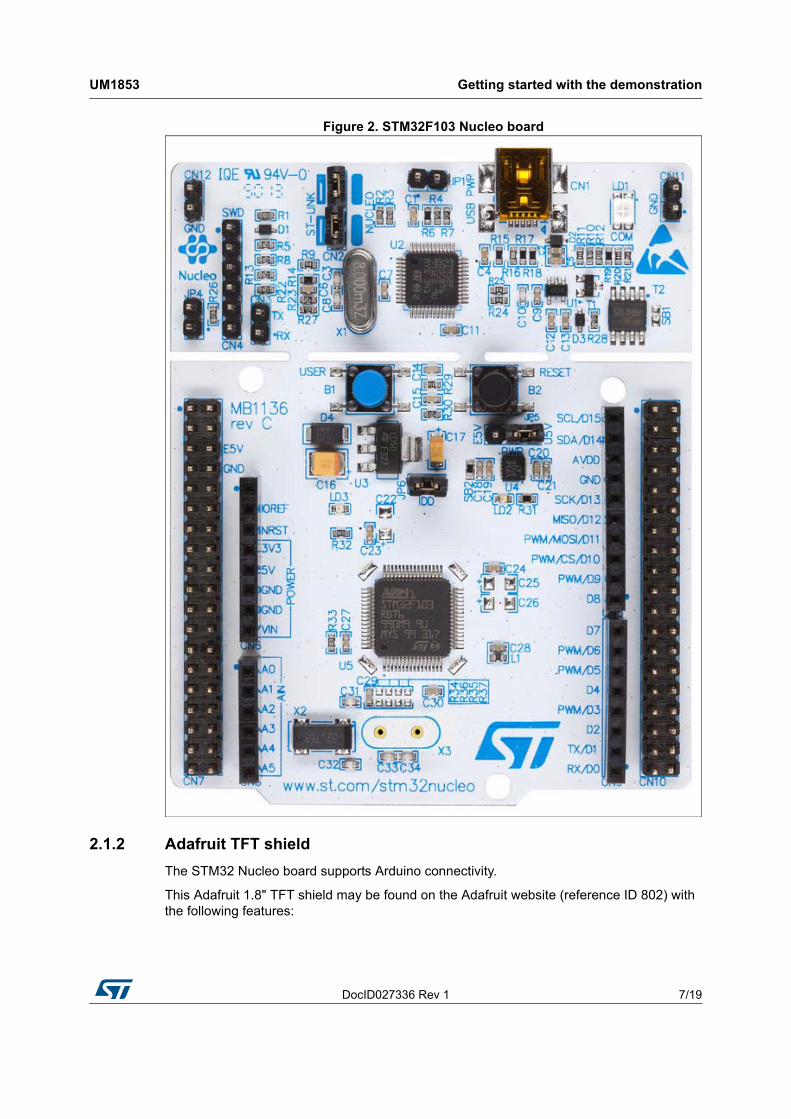
Figure 2. STM32F103 Nucleo board
2.1.2 Adafruit TFT shield
The STM32 Nucleo board supports Arduino connectivity.
This Adafruit 1.8" TFT shield may be found on the Adafruit website (reference ID 802) with the following features:
Getting started with the demonstration UM1853
8/19 DocID027336 Rev 1
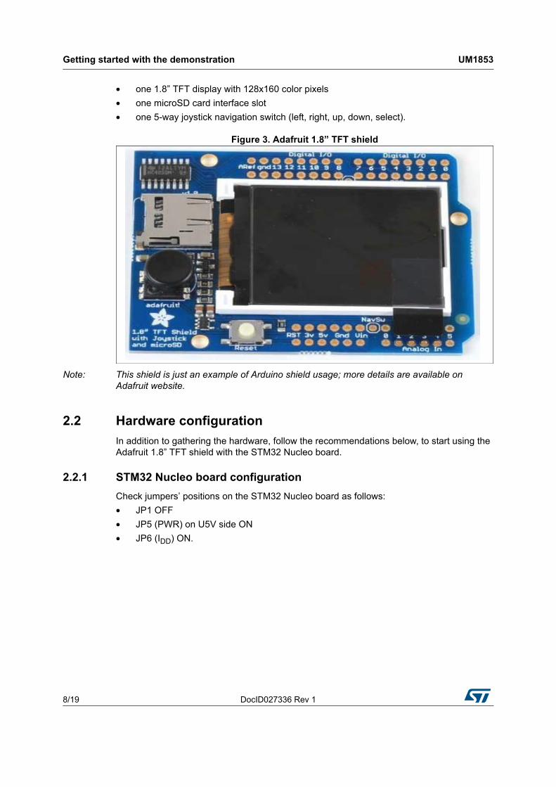
• one 1.8” TFT display with 128x160 color pixels
• one microSD card interface slot
• one 5-way joystick navigation switch (left, right, up, down, select).
Figure 3. Adafruit 1.8” TFT shield
Note: This shield is just an example of Arduino shield usage; more details are available on Adafruit website.
2.2 Hardware configuration
In addition to gathering the hardware, follow the recommendations below, to start using the Adafruit 1.8” TFT shield with the STM32 Nucleo board.
2.2.1 STM32 Nucleo board configuration
Check jumpers’ positions on the STM32 Nucleo board as follows:
• JP1 OFF
• JP5 (PWR) on U5V side ON
• JP6 (IDD) ON.
DocID027336 Rev 1 9/19
UM1853 Getting started with the demonstration
18
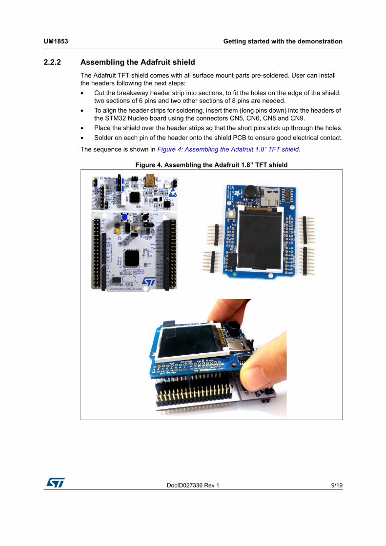
2.2.2 Assembling the Adafruit shield
The Adafruit TFT shield comes with all surface mount parts pre-soldered. User can install the headers following the next steps:
• Cut the breakaway header strip into sections, to fit the holes on the edge of the shield: two sections of 6 pins and two other sections of 8 pins are needed.
• To align the header strips for soldering, insert them (long pins down) into the headers of the STM32 Nucleo board using the connectors CN5, CN6, CN8 and CN9.
• Place the shield over the header strips so that the short pins stick up through the holes.
• Solder on each pin of the header onto the shield PCB to ensure good electrical contact.
The sequence is shown in Figure 4: Assembling the Adafruit 1.8” TFT shield.
Figure 4. Assembling the Adafruit 1.8” TFT shield

Demonstration firmware package UM1853
10/19 DocID027336 Rev 1
3 Demonstration firmware package
3.1 Demonstration repository
The Nucleo demonstration is provided within the STM32CubeF1 firmware package, as shown in Figure 5: Folder structure.
Figure 5. Folder structure
The demonstration sources are located in the projects folder of the STM32Cube package for the STM32F103RB Nucleo boards.The sources are divided into five groups described as follows:
1. Binary: demonstration binary file in Hex format
2. Inc: contains the demonstration header files
3. Src: contains the demonstration source files
4. Project settings: a folder per toolchain containing the project settings and the linker files.
DocID027336 Rev 1 11/19
UM1853 Demonstration firmware package
18
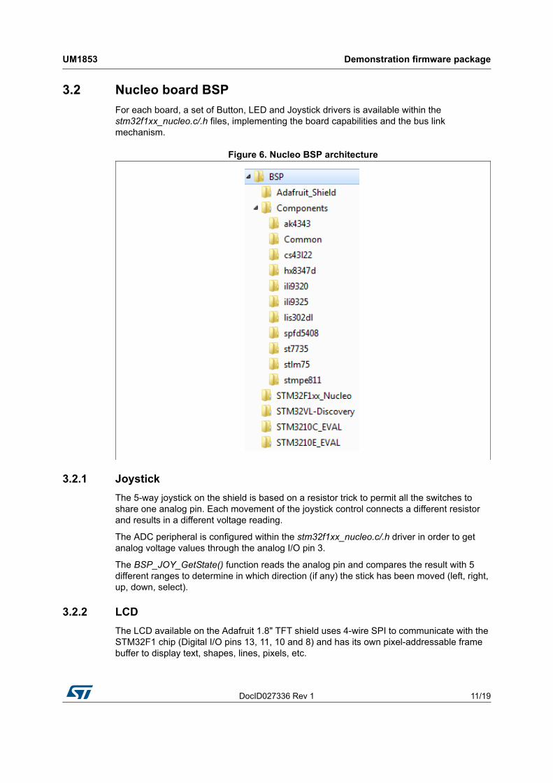
3.2 Nucleo board BSP
For each board, a set of Button, LED and Joystick drivers is available within the stm32f1xx_nucleo.c/.h files, implementing the board capabilities and the bus link mechanism.
Figure 6. Nucleo BSP architecture
3.2.1 Joystick
The 5-way joystick on the shield is based on a resistor trick to permit all the switches to share one analog pin. Each movement of the joystick control connects a different resistor and results in a different voltage reading.
The ADC peripheral is configured within the stm32f1xx_nucleo.c/.h driver in order to get analog voltage values through the analog I/O pin 3.
The BSP_JOY_GetState() function reads the analog pin and compares the result with 5 different ranges to determine in which direction (if any) the stick has been moved (left, right, up, down, select).
3.2.2 LCD
The LCD available on the Adafruit 1.8" TFT shield uses 4-wire SPI to communicate with the STM32F1 chip (Digital I/O pins 13, 11, 10 and 8) and has its own pixel-addressable frame buffer to display text, shapes, lines, pixels, etc.

Demonstration firmware package UM1853
12/19 DocID027336 Rev 1
The SPI peripheral is configured within the stm32f1xx_nucleo.c/.h driver which contains also the SPI bus link mechanism and IO operations.
The LCD is controlled by a dedicated BSP LCD driver stm32_adafruit_lcd.c/.h which uses the st7735 component that exports in a generic way the LCD IO operations needed for its process.
3.2.3 MicroSD
The microSD slot available on the Adafruit 1.8" TFT shield uses 4-wire SPI to communicate with the STM32F1 chip (Digital I/O pins 13, 12, 11 and 4).
The SPI peripheral is configured within the stm32f1xx_nucleo.c/.h driver which contains also the SPI bus link mechanism and IO operations.
The microSD is controlled by a dedicated BSP SD driver stm32_adafruit_sd.c/.h which exports in a generic way the SD IO operations needed for its process.

DocID027336 Rev 1 13/19
UM1853 Demo functional description
18
4 Demo functional description
In this demonstration application, we will show how to use the STM32CubeF1 firmware package with the NUCLEO-F103RB board and the Adafruit 1.8” TFT shield to display a 128x160 pixel full color bitmap from a microSD card using the FatFS file system.
To start with this demonstration application, user has to copy the provided 128x160 pixel bitmap pictures, available within the FW package under “\Media” folder, to the root directory of a FAT formatted microSD card and insert the microSD card into the Adafruit shield microSD holder.
Note that the microSD card can have a storage capacity up to 4GBytes (SDSC) and that the bitmap images must have the properties detailed in Table 1: Bitmap image properties.
Once started, the application checks the availability of Adafruit 1.8" TFT shield on top of STM32 Nucleo board. This is done by reading the state of IO PB.00 pin (mapped to Joystick available on the shield). If the state of PB.00 is high then the shield is available.
If the Adafruit 1.8" TFT shield is not available, the LED2 is toggling with a frequency equal to ~1Hz. A second press on the User button lets LED2 toggling with a second frequency equal to ~5Hz. The third press, changes LED2 toggling frequency to ~10Hz. The described process is done in an infinite loop.
If the Adafruit 1.8" TFT shield is available, LED2 is turned ON, because it's sharing the same pin with the SPI CLK signal used to communicate with the LCD and microSD available on the shield.
A menu is displayed on Adafruit 1.8" TFT describing the demonstration application, as shown in Figure 7: Demonstration application menu.
Figure 7. Demonstration application menu
Table 1. Bitmap image properties
Dimensions 128 x 160
Width 128 pixels
Height 160 pixels
Bit depth 16
Item type BMP file
Name Must not exceed 11 characters (including bmp extension).

Demo functional description UM1853
14/19 DocID027336 Rev 1
User has to follow the instructions below:
• Press the Joystick DOWN to continue menu display (see Figure 8: Reading the Adafruit shield Joystick)
• Choose one of the available display modes (manual and automatic) using the Joystick button:
– Automatic mode: by pressing Joystick DOWN
The bitmap images available on the microSD card are displayed sequentially in a forever loop.
– Manual mode: by pressing Joystick UP
The bitmap images available on the microSD card are displayed by pressing Joystick RIGHT to display next images, or Joystick LEFT to display previous one. Pressing long (~1s) the Joystick SEL, switches the display mode from manual to automatic.
Figure 8. Reading the Adafruit shield Joystick
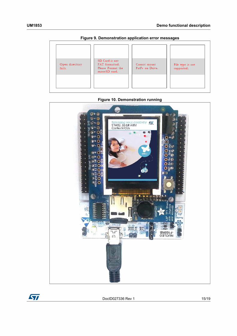
Note that the application manages some errors (refer to Figure 9: Demonstration application error messages), that can occur during the access to microSD card to load the bitmap images:
• If the microSD card is not FAT formatted, a message will be displayed on TFT. In this case, format the microSD card and put into its root directory the bmp files available within the FW package under \Media folder.
• If the content of the microSD card is other than a bitmap file, a message will be displayed on TFT mentioning that it is not supported. User has to ensure that the files, available under the microSD card root directory, are respecting the above described bitmap properties.
DocID027336 Rev 1 15/19
UM1853 Demo functional description
18
Figure 9. Demonstration application error messages
Figure 10. Demonstration running

Demo functional description UM1853
16/19 DocID027336 Rev 1
4.1 Programming firmware application
To program the STM32 Nucleo board with the demonstration application, proceed as follows:
1. Install the preferred Integrated Development Environment (IDE)
2. Install the ST-LINK/V2.1 driver available on ST website.
There are two ways of programming the STM32 Nucleo board:
• Method 1:
Upload the STM32CubeF1_Demo_Nucleo.hex from the firmware package available under:
– Projects\STM32F103RB-Nucleo\Demonstrations\Binary
using the user’s preferred in-system programming tool.
• Method 2:
Choose one of two supported tool chains (IAR®/ Keil®/Atollic®) and follow the steps below:
– Open the application folder: Projects\STM32F103RB-Nucleo\Demonstrations\
– Chose the desired IDE project (EWARM for IAR, MDK-ARM for Keil and TrueSTUDIO for Atollic)
– Double click on the project file (for example Project.eww for EWARM)
– Rebuild all files: Go to Project and select Rebuild all
– Load the project image: Go to Project and select Debug
– Run the program: Go to Debug and select Go.
The demonstration software as well as other software examples that allow user to discover the STM32 microcontroller features, are available on ST website at www.st.com/stm32nucleo.

DocID027336 Rev 1 17/19
UM1853 FAQs
18
5 FAQs
How can I use this application to display my own images?
Use any image editing tool and crop your image to no larger than 160 pixels high and 128 pixels wide. Save it as a 16-bit color BMP format file.
Can I display more bitmap files?
Yes. You can display more pictures, by copying them under the microSD root directory. Just modify the define value of MAX_BMP_FILES constant to the desired number of files. In this case, you must fine tune the _FS_LOCK value, defining the number of files that can be opened simultaneously, under “ffconf.h” the FatFs configuration file.
What about putting the bitmap files not under the root directory of the microSD?
Once put under another folder different from the root directory, the bitmap files cannot be accessed by the demonstration application. The “File type not supported” error message is displayed on the LCD.
To make it work you have to add the new directory path within f_open() and f_opendir() FatFs APIs calls’ under the fatfs_storage.c file.

Revision history UM1853
18/19 DocID027336 Rev 1
6 Revision history
Table 2. Document revision history
Date Revision Changes
06-Feb-2015 1 Initial release.
DocID027336 Rev 1 19/19
UM1853
19
IMPORTANT NOTICE – PLEASE READ CAREFULLY
STMicroelectronics NV and its subsidiaries (“ST”) reserve the right to make changes, corrections, enhancements, modifications, and improvements to ST products and/or to this document at any time without notice. Purchasers should obtain the latest relevant information on ST products before placing orders. ST products are sold pursuant to ST’s terms and conditions of sale in place at the time of order acknowledgement.
Purchasers are solely responsible for the choice, selection, and use of ST products and ST assumes no liability for application assistance or the design of Purchasers’ products.
No license, express or implied, to any intellectual property right is granted by ST herein.
Resale of ST products with provisions different from the information set forth herein shall void any warranty granted by ST for such product.
ST and the ST logo are trademarks of ST. All other product or service names are the property of their respective owners.
Information in this document supersedes and replaces information previously supplied in any prior versions of this document.
© 2015 STMicroelectronics – All rights reserved