stock towers - print us 5 with acces
TRANSCRIPT
www.trylon.com
STOCK
TOWER
BROCHUREU.S. Version

[email protected] Telephone: (519) 669-5421 Ext. 356 www.trylon.com
SUPERTITAN WELD
SuperTITAN WELD SPECIFICATIONS
SuperTITAN WELD APPLICATIONS
THE SuperTITAN WELD DIFFERENCE• Only All-Weld Self-Support available through distribu on• 3 hole bolts pa ern and fl at fl anges• Towers ship nested to minimizes freight costs
• Oil and gas sites• Railways: minimizes access me required• Tower Contractors: minimizes assembly • Ideal loading capacity for SCADA, WISP, Broadband and
2-Way applica ons
• All-Weld sec ons minimize assembly and installa on me• Flat fl anges provides an easy connec on between sec ons (3
bolts per leg)• Designed to conform with ANSI-TIA-222 F&G Standard• Climbing horizontals on one face (7/8” or 3/4”)• Every 5th sec on nests for reduced freight costs• Maximum height: 150 • Sec on height: 10
The fl at pads make installa on easy
The SuperTitan Weld is designed to meet market loading requirements and conforms to ANSI-TIA 222-G Standard. Trylon understands the importance of minimizing freight costs and as a result the tower is designed to ship nested.
The all-weld design uses fl at pads allows for easy connec ons, which further minimizes assembly and installa on me. The tower ships with integral climbing face and transmission line supports which off er addi onal value and eliminate the need to purchase separately. P.E. stamped drawings are available.
Integral transmission line supports
Tower ships nested to minimize freight

[email protected] Telephone: (519) 669-5421 Ext. 356 www.trylon.com
SUPERTITAN WELD
TIA 222-G Importance Class I Importance Class IIHEIGHT MODEL 90 110 130 90 110 130
20’ W700 232 150 98 200 126 8220’ W600 188 122 84 162 104 7220’ W500 186 120 82 160 102 6820’ W400 184 118 80 158 100 6620’ W300 182 116 78 156 98 6420’ W200 178 114 76 154 96 6220’ W100 86 54 38 74 46 3230’ W700 212 136 86 182 114 7030’ W600 170 110 76 148 94 6430’ W500 168 108 74 146 92 6230’ W400 166 106 72 144 90 6030’ W300 164 104 70 142 88 5830’ W200 124 78 52 106 66 4630’ W100 78 50 34 66 44 3040’ W700 198 126 78 170 106 6040’ W600 160 104 72 138 88 5840’ W500 158 102 68 136 86 5640’ W400 156 100 66 134 84 5440’ W300 154 98 64 132 82 5240’ W200 116 72 50 98 62 4240’ W100 72 46 32 62 40 2850’ W700 188 118 72 162 98 5450’ W600 152 98 68 130 84 5250’ W500 150 96 64 128 82 5050’ W400 148 94 62 126 80 4850’ W300 126 76 50 106 62 4250’ W200 110 68 46 94 56 3850’ W100 68 44 30 58 38 2660’ W700 184 112 66 156 92 5060’ W600 146 94 64 126 80 4860’ W500 144 92 60 124 78 4660’ W400 142 90 58 122 76 4460’ W300 120 72 46 100 60 4060’ W200 92 52 34 76 46 3060’ W100 66 42 30 56 36 2470’ W700 180 106 60 152 86 4870’ W600 140 90 58 122 78 4670’ W500 138 88 56 120 76 4470’ W400 136 82 52 116 66 4270’ W300 114 68 46 96 56 3870’ W200 88 52 32 72 44 2870’ W100 64 40 24 54 32 18
TIA 222-G Importance Class I Importance Class IIHEIGHT MODEL 90 110 130 90 110 130
80’ W700 180 102 54 150 80 4480’ W600 136 88 52 118 74 4280’ W500 134 86 50 115 72 4080’ W400 132 78 48 112 64 3880’ W300 108 60 38 90 50 3080’ W200 84 50 30 70 42 2680’ W100 62 38 24 52 30 1890’ W700 182 98 52 148 76 4690’ W600 134 86 50 114 72 4490’ W500 132 84 48 111 70 4290’ W400 130 74 46 108 60 4090’ W300 104 56 36 86 48 3090’ W200 80 46 30 66 40 2290’ W100 60 36 22 52 30 16
100’ W600 130 84 50 112 70 40100’ W500 128 82 48 110 68 38100’ W400 126 72 46 104 58 36100’ W300 100 54 34 82 46 30100’ W200 78 46 28 64 38 20100’ W100 58 34 20 50 30 14110’ W500 130 80 46 110 66 34110’ W400 122 70 44 102 56 32110’ W300 98 52 32 80 46 28110’ W200 76 46 26 62 36 20110’ W100 56 34 18 48 28 14120’ W400 120 68 44 98 54 30120’ W300 94 52 32 78 46 26120’ W200 74 44 26 60 34 18120’ W100 54 32 18 46 28 14130’ W300 92 52 30 74 44 26130’ W200 72 42 24 58 32 16130’ W100 54 30 16 46 26 14140’ W200 70 42 24 56 32 16140’ W100 52 30 16 46 26 14150’ W100 52 30 14 46 26 12
WIND LOAD CHARTS
1) Importance Class I based on 30mph Service Wind Speed, 0” of Radial Icing, load is centrally balanced above tower top, no tx lines considered.
2) Importance Class II based on 40mph Service Wind Speed, 0.75” of Radial Icing, load is centrally balanced above tower top, no tx lines considered.

[email protected] Telephone: (519) 669-5421 Ext. 356 www.trylon.com
SUPERTITAN KD
SuperTITAN KD SPECIFICATIONS
SuperTITAN KD APPLICATIONS
THE SuperTITAN KD DIFFERENCE• Maximum height 190 compared to 150 for compe tors• New innova ve packaging• Dras cally reduces freight costs• Product in stock at distributor loca ons • Reduced lead- mes vs. direct shipments from manufacturer
• Emergency Services (Police, Fire, etc.)• Increased tower capacity
• SCADA Systems• Ideally suited for base sta ons with larger loading
parameters• Broadband• Base Sta on towers
• Brand New Packaging Process• Minimize freight costs (weight & dimensions)• Minimizes storage space• Improved economic footprint
• All members are hot-dip galvanized throughout• Designed to conform with TIA/EIA standard• Maximum height: 190 • Sec on height: 10
Trylon’s SuperTitan KD bridges the cost gap between the lighter-weight Titan towers and more costly custom-designed towers.
The SuperTitan KD is a modular tower that can be built up to 190 feet high. Consis ng of 21 standard sec ons, each 10 feet high, this modular system can be confi gured to create towers of varying heights and loading capaci es. The SuperTitan KD design conforms to ANSI-TIA-222 F&G Standard and can be stamped by a professional engineer.
SuperTitan KD Tower
30’ SuperTitan KD tower
New! SuperTitan KD packaging method

[email protected] Telephone: (519) 669-5421 Ext. 356 www.trylon.com
ACCESSACCESS
SUPERTITAN KD
WIND LOAD CHARTSEIA Rev. G Class 1:
0.75” Ice at 90/ 105/ 120 mph (round)
EIA Rev. G Class 2: 0.75” Ice at 90/ 105/
120 mph (round)
Height Model 90 105 120 90 105 12020’ S100 78 52 38 66 46 3220’ S200 92 64 46 78 54 4020’ S300 108 74 54 92 64 4630’ S100 46 30 18 38 24 1430’ S200 52 34 24 44 30 1830’ S300 60 40 28 50 32 2240’ S100 28 14 8 22 12 440’ S200 32 18 10 26 14 640’ S300 56 36 24 46 30 1840’ S400 104 72 52 88 60 4450’ S100 14 6 - 12 - -50’ S200 30 16 8 24 12 450’ S300 52 34 22 44 28 1650’ S400 82 50 32 66 42 2450’ S500 88 54 34 72 44 2850’ S600 128 84 54 108 68 4460’ S100 14 4 - 10 - -60’ S200 28 14 6 22 10 260’ S300 50 30 16 42 22 1060’ S400 56 32 16 46 24 1260’ S500 82 50 32 66 40 2470’ S100 14 2 - 8 - -70’ S200 26 14 4 20 10 -70’ S300 38 16 4 28 12 -70’ S400 52 30 14 44 22 1070’ S500 78 48 30 62 38 2070’ S600 88 48 28 66 36 1670’ H610 88 48 28 66 36 1680’ S100 12 2 - 6 - -80’ S200 22 6 - 14 - -80’ S300 34 14 2 26 10 -80’ S400 50 30 14 40 20 880’ S500 58 30 14 46 20 480’ H500 58 30 14 46 20 480’ H510 58 30 14 46 20 490’ S100 10 - - 4 - -90’ S200 14 - - 4 - -90’ S300 30 14 - 24 8 -90’ S400 42 16 - 30 8 -90’ H400 42 16 - 30 8 -
EIA Rev. G Class 1: 0.75” Ice at 90/ 105/
120 mph (round)
EIA Rev. G Class 2: 0.75” Ice at 90/ 105/
120 mph (round)
Height Model 90 105 120 90 105 12090’ H410 42 16 - 30 8 -90’ S610 78 42 18 58 30 8
100’ H200 18 2 - 12 - -100’ H310 28 6 - 14 - -100’ S510 52 26 6 40 14 -100’ S610 72 36 14 52 26 4110’ H210 14 - - 6 - -110’ S410 36 14 - 26 2 -110’ S510 50 22 2 36 12 -110’ S610 66 30 6 48 16 -120’ H110 6 - - - - -120’ S310 22 2 - 14 - -120’ S410 32 12 - 22 - -120’ S510 48 16 - 32 6 -120’ S610 58 24 - 44 12 -130’ S310 14 - - 8 - -130’ S410 30 6 - 20 - -130’ S510 46 14 - 30 - -130’ S610 52 20 - 40 8 -130’ S710 76 32 8 52 18 -140’ S310 14 - - 6 - -140’ S410 30 - - 14 - -140’ S510 42 10 - 28 - -140’ S610 52 18 - 36 6 -140’ S710 72 30 6 50 16 -140’ S810 98 46 18 70 30 4150’ S310 14 - - 6 - -150’ S410 30 - - 14 - -150’ S510 40 8 - 24 - -150’ S610 50 14 - 34 4 -150’ S710 68 30 4 48 14 -160’ S310 14 - - 4 - -160’ S410 28 - - 14 - -160’ S510 36 6 - 22 - -160’ S610 48 14 - 30 2 -170’ S310 12 - - 2 - -170’ S410 24 - - 12 - -170’ S510 34 4 - 18 - -180’ S310 12 - - - - -180’ S410 22 - - 10 - -

[email protected] Telephone: (519) 669-5421 Ext. 356 www.trylon.com
SUPERTITAN MAX
SuperTITAN MAX SPECIFICATIONS
SuperTITAN MAX APPLICATIONS
THE SuperTITAN MAX DIFFERENCE• Lead- me: 3 weeks
• Compared to 6-8 weeks for similar capacity custom towers
• 19 sec ons ideal for interna onal shipments• Pre-engineered, tower drawings and founda on drawings
available prior to tower shipment
• Covers almost any applica on below cellular grade• Ideal for interoperability solu ons• Large load and tall tower requirement
• Tallest stock product tower off ered• Ships from Trylon• 19 sec on (ships unassembled)• P.E. Stamp drawings included in price • Designed to conform with ANSI-TIA-222 F&G Standard• Maximum height: 251 • Sec on height: 19
Designed using the same basic modular confi gura on as the SuperTitanKD model, the SuperTitan MAX features a wide range of heights and op ons for increasing strength and capacity.
The SuperTitan MAX is shipped in 19 foot sec ons which can be assembled to a maximum height of 251 feet, making it Trylon’s tallest self-suppor ng stocked tower.
P.E. stamped drawings are also available for this product line, making it a cost-eff ec ve alterna ve to a custom tower.

[email protected] Telephone: (519) 669-5421 Ext. 356 www.trylon.com
SUPERTITAN MAX
WIND LOAD CHARTSTIA/EIA Rev. G
Importance Class 1: 0.75” Icing @ 40 mph
TIA/EIA Rev. G Importance Class 2:
0.75 @ 40 mph
Round RoundHEIGHT MODEL 90 110 130 90 110 130
118’ M110 34 12 0 26 4 0118’ M210 74 36 12 58 26 2118’ M310 126 64 30 102 50 14118’ M410 136 84 36 116 64 18118’ M510 262 158 72 224 118 48127’ M200 48 22 0 38 14 0127’ M300 106 50 14 82 34 0127’ M400 128 66 20 106 46 4127’ M500 248 118 46 196 82 30127’ M600 270 162 80 226 132 46137’ M110 30 10 0 22 2 0137’ M210 70 32 4 54 22 0137’ M310 120 48 8 96 30 0137’ M410 132 82 30 112 54 14137’ M510 252 146 52 216 106 30146’ M200 46 18 0 36 10 0146’ M300 100 34 0 78 16 0146’ M400 122 56 14 102 40 0146’ M500 234 108 34 184 74 14146’ M600 244 138 14 202 110 28156’ M110 30 8 0 20 0 0156’ M210 66 24 0 52 8 0156’ M310 116 46 2 92 26 0156’ M410 128 76 20 108 50 0156’ M510 244 136 14 210 92 0165’ M200 46 14 0 34 0 0165’ M300 94 30 0 68 14 0165’ M400 118 52 8 98 32 0165’ M500 224 98 12 174 62 0165’ M600 252 142 16 212 72 0175’ M110 28 4 0 18 0 0175’ M210 64 16 0 52 2 0175’ M310 112 38 0 84 20 0175’ M410 124 68 0 106 46 0175’ M510 238 126 0 204 56 0
TIA/EIA Rev. G Importance Class 1:
0.75” Icing @ 40 mph
TIA/EIA Rev. G Importance Class 2:
0.75 @ 40 mph
Round RoundHEIGHT MODEL 90 110 130 90 110 130
184’ M200 42 10 0 32 0 0184’ M300 90 26 0 60 10 0184’ M400 114 48 0 94 30 0184’ M500 214 92 0 166 51 0184’ M600 230 46 0 190 58 0194’ M110 26 6 0 16 0 0194’ M210 62 14 0 46 0 0194’ M310 108 32 0 78 14 0194’ M410 120 62 0 102 21 0194’ M510 232 46 0 190 28 0203’ M200 40 4 0 30 0 0203’ M300 88 20 0 54 4 0203’ M400 112 46 0 92 8 0203’ M500 206 46 0 156 11 0203’ M600 238 52 0 200 16 0213’ M110 26 0 0 16 0 0213’ M210 60 12 0 46 0 0213’ M310 104 30 0 72 0 0213’ M410 118 38 0 100 0 0213’ M510 228 41 0 174 0 0222’ M200 40 0 0 30 0 0222’ M300 82 16 0 52 0 0222’ M400 108 26 0 90 0 0222’ M500 198 32 0 142 0 0232’ M110 24 0 0 14 0 0232’ M210 58 8 0 42 0 0232’ M310 100 14 0 66 0 0232’ M410 116 18 0 98 0 0241’ M200 38 0 0 30 0 0241’ M300 76 4 0 50 0 0241’ M400 106 8 0 86 0 0251’ M110 22 0 0 14 0 0251’ M210 54 0 0 38 0 0251’ M310 96 0 0 60 0 0

[email protected] Telephone: (519) 669-5421 Ext. 356 www.trylon.com
TITAN TOWER
TITAN SPECIFICATIONS
TITAN APPLICATIONS
THE TITAN DIFFERENCE• Maximum height, minimum cost Self-Support op on • Tower ships assembled• 96 tower ships on one skid
• Ideal for SCADA/remote monitoring• Two-Way radio
• EMS, Police, Fire, etc.• Companies with personal fl eets (trucking companies etc.)
• Wireless Internet Service Providers (WISP)• Surveillance applica ons
• Camera towers
• Self-Support (free-standing)• 45” face width• “Survival” Tower Line• Maximum height at minimum cost• Ships assembled in 8 sec ons to minimize installa on and
assembly me• Ships nested to minimize freight cost• Maximum height: 96 • Sec on height: 8
The Titan tower has been a favourite in light duty applica ons for more than 30 years. With more than 15,000 Titan towers installed in North America, this model has been used for Telemetry, Satellite TV, Wireless LAN, Wireless internet, mobile Radio and Amateur applica ons.
The Titan is a versa le, modular, pre-engineered tower that requires a minimal footprint and is available in heights ranging from 16 to 96 feet.
Titan tower - 80 T400 model
Tower ships nested to minimize freight
Typical antenna install on a Titan tower
[email protected] Telephone: (519) 669-5421 Ext. 356 www.trylon.com
TITAN TOWER
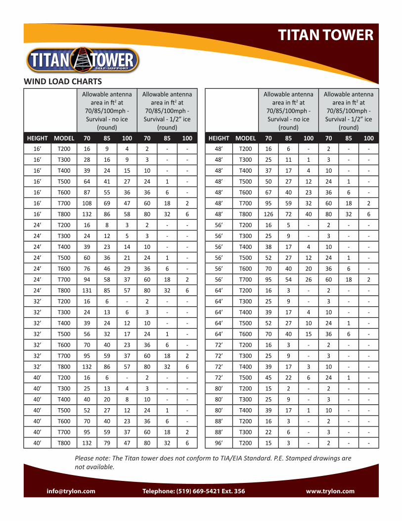
WIND LOAD CHARTSAllowable antenna
area in 2 at 70/85/100mph - Survival - no ice
(round)
Allowable antenna area in 2 at
70/85/100mph - Survival - 1/2” ice
(round)HEIGHT MODEL 70 85 100 70 85 100
16’ T200 16 9 4 2 - -
16’ T300 28 16 9 3 - -
16’ T400 39 24 15 10 - -
16’ T500 64 41 27 24 1 -
16’ T600 87 55 36 36 6 -
16’ T700 108 69 47 60 18 2
16’ T800 132 86 58 80 32 6
24’ T200 16 8 3 2 - -
24’ T300 24 12 5 3 - -
24’ T400 39 23 14 10 - -
24’ T500 60 36 21 24 1 -
24’ T600 76 46 29 36 6 -
24’ T700 94 58 37 60 18 2
24’ T800 131 85 57 80 32 6
32’ T200 16 6 - 2 - -
32’ T300 24 13 6 3 - -
32’ T400 39 24 12 10 - -
32’ T500 56 32 17 24 1 -
32’ T600 70 40 23 36 6 -
32’ T700 95 59 37 60 18 2
32’ T800 132 86 57 80 32 6
40’ T200 16 6 - 2 - -
40’ T300 25 13 4 3 - -
40’ T400 40 20 8 10 - -
40’ T500 52 27 12 24 1 -
40’ T600 70 40 23 36 6 -
40’ T700 95 59 37 60 18 2
40’ T800 132 79 47 80 32 6
Allowable antenna area in 2 at
70/85/100mph - Survival - no ice
(round)
Allowable antenna area in 2 at
70/85/100mph - Survival - 1/2” ice
(round)HEIGHT MODEL 70 85 100 70 85 100
48’ T200 16 6 - 2 - -
48’ T300 25 11 1 3 - -
48’ T400 37 17 4 10 - -
48’ T500 50 27 12 24 1 -
48’ T600 67 40 23 36 6 -
48’ T700 95 59 32 60 18 2
48’ T800 126 72 40 80 32 6
56’ T200 16 5 - 2 - -
56’ T300 25 9 - 3 - -
56’ T400 38 17 4 10 - -
56’ T500 52 27 12 24 1 -
56’ T600 70 40 20 36 6 -
56’ T700 95 54 26 60 18 2
64’ T200 16 3 - 2 - -
64’ T300 25 9 - 3 - -
64’ T400 39 17 4 10 - -
64’ T500 52 27 10 24 1 -
64’ T600 70 40 15 36 6 -
72’ T200 16 3 - 2 - -
72’ T300 25 9 - 3 - -
72’ T400 39 17 3 10 - -
72’ T500 45 22 6 24 1 -
80’ T200 15 2 - 2 - -
80’ T300 25 9 - 3 - -
80’ T400 39 17 1 10 - -
88’ T200 16 3 - 2 - -
88’ T300 22 6 - 3 - -
96’ T200 15 3 - 2 - -
Please note: The Titan tower does not conform to TIA/EIA Standard. P.E. Stamped drawings are not available.
[email protected] Telephone: (519) 669-5421 Ext. 356 www.trylon.com
STG SERIES
STG SERIES SPECIFICATIONS
STG SERIES APPLICATIONS
THE STG SERIES DIFFERENCE• Solid round leg design compared to pipe leg design:
• Increased strength• Preven ng internal leg corrosion• Elimina ng ice buildup
• Oil and gas sites• Perfect for 40 SCADA towers• Wind Monitoring sites• Small radio towers• WISPs
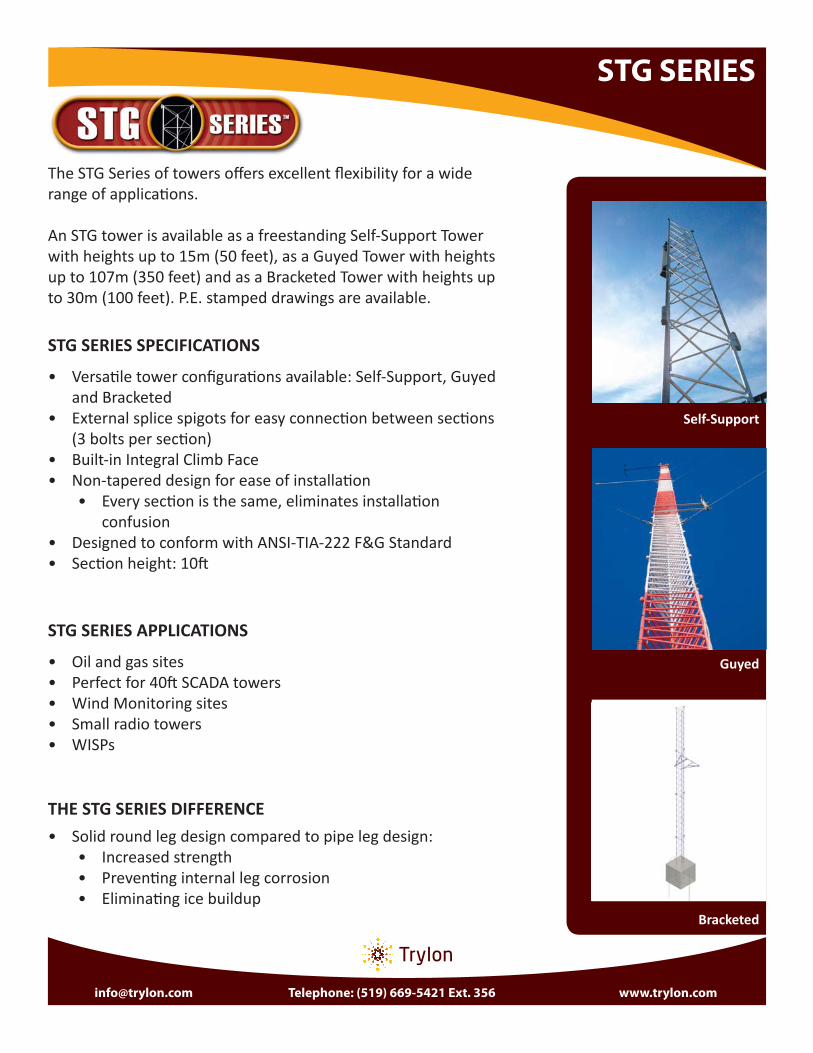
• Versa le tower confi gura ons available: Self-Support, Guyed and Bracketed
• External splice spigots for easy connec on between sec ons (3 bolts per sec on)
• Built-in Integral Climb Face• Non-tapered design for ease of installa on
• Every sec on is the same, eliminates installa on confusion
• Designed to conform with ANSI-TIA-222 F&G Standard• Sec on height: 10
Self-Support
The STG Series of towers off ers excellent fl exibility for a wide range of applica ons.
An STG tower is available as a freestanding Self-Support Tower with heights up to 15m (50 feet), as a Guyed Tower with heights up to 107m (350 feet) and as a Bracketed Tower with heights up to 30m (100 feet). P.E. stamped drawings are available.
Bracketed
Guyed
[email protected] Telephone: (519) 669-5421 Ext. 356 www.trylon.com
STG SERIES
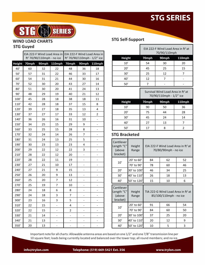
WIND LOAD CHARTS
EIA 222-F Wind Load Area in 2 70/90/110mph - no ice
EIA 222-F Wind Load Area in 2 70/90/110mph - 1/2” ice
Height 70mph 90mph 110mph 70mph 90mph 110mph40’ 60 32 22 48 36 1850’ 57 31 22 46 33 1760’ 54 31 21 44 30 1670’ 52 30 20 43 27 1480’ 51 30 20 41 24 1390’ 48 29 19 40 21 12
100’ 45 28 18 38 18 11110’ 42 28 18 37 15 8120’ 39 27 18 35 13 4130’ 37 27 17 33 12 2140’ 36 26 16 31 10 -150’ 34 25 15 29 9 -160’ 33 25 15 28 8 -170’ 32 24 14 26 7 -180’ 31 24 13 25 5 -190’ 30 23 13 23 4 -200’ 29 22 12 22 3 -210’ 28 22 12 20 - -220’ 28 22 11 19 - -230’ 27 21 10 17 - -240’ 27 21 9 15 - -250’ 26 20 9 13 - -260’ 25 20 7 12 - -270’ 25 19 7 10 - -280’ 24 18 6 8 - -290’ 24 18 3 7 - -300’ 23 16 3 5 - -310’ 22 15 - 4 - -320’ 22 15 - 2 - -330’ 21 14 - - - -340’ 21 13 - - - -350’ 20 13 - - - -
Survival Wind Load Area in 2 at 70/90/110mph - 1/2” ice
Height 70mph 90mph 110mph10’ 90 50 3620’ 75 44 2830’ 45 24 1440’ 27 13 750’ 17 8 2
EIA 222-F Wind Load Area in 2 at 70/90/110mph
Height 70mph 90mph 110mph10’ 54 30 2020’ 45 25 1530’ 25 12 740’ 12 7 -50’ 7 - -
STG GuyedSTG Self-Support
STG BracketedCan lever Length “C”
(above bracket)
Height Range
EIA 222-F Wind Load Area in 2 at 70/80/90mph - no ice
10’20’ to 60’ 84 62 5270’ to 90’ 78 60 46
20’ 30’ to 100’ 46 34 2530’ 40’ to 110’ 26 18 1340’ 50’ to 120’ 15 10 6
Can lever Length “C”
(above bracket)
Height Range
TIA 222-G Wind Load Area in 2 at 85/100/110mph - no ice
10’20’ to 60’ 91 66 5470’ to 90’ 84 60 50
20’ 30’ to 100’ 37 25 2030’ 40’ to 110’ 20 12 940’ 50’ to 120’ 10 5 3
Important note for all charts: Allowable antenna areas are based on one 1/2” and one 7/8” transmission line per 10 square feet; loads being currently located and balanced over the tower top; all round members; and no ice.

[email protected] Telephone: (519) 669-5421 Ext. 356 www.trylon.com
ACCESSORIES
• Mounts to up to 11” OD Legs Tapered or Vertical
• Light 2’ to 6’ (in 1’ increments), Medium 1’ to 3’ (in 1’ increments), Heavy 6’ and 8’
• Standoff s are a perfect mounting solution for wireless omnidirectional antennas or dishes.
STANDOFF MOUNTS
Arms• Single Arm Standoff s are per-
fect for tower off sets. Alone they provide an off set for mounting antenna pipes. As a group they provide a support system for multiple antennas or face mounted sector frames.
• Wireless Arms are used to install small antennas to a tower struc-ture. Made from 11" OD structural rails and are off ered in fi ve stan-dard widths.
• Monopole Components: attach directly to Ring Assemblies or standoff s using two 1/2” U-bolt assemblies.
• Monopole Wireless Arm Assemblies: used for single sector applications and can support up to three antennas.
• Monopole Standoff with Pipe Mount: Typically used for single antenna systems, but can also be used as a part of a horizontal system.
• Monopole T-Arm Kit: used for easy sector installation. Comes in three sizes; 10, 12’, and 15' outside pipe centered distance.
• Monopole Co-Location T-Frame Kit: A complete co-location solution. They come standard with our 12" to 60” universal ring assembly, three adjustable standoff s, and three HSS cross arms with welded connection plates available.
Monopoles
Platforms• Low Profi le Co-Location Platform:
Made standard with a universal ring assembly and three of each of the following: standoff s, knee braces, and cross arms.
• Handrails for Low Profi le Platform: Provides an enclosed working area for increased personal safety, while also adapting both our mono pole and rotatable co-location platforms to allow two attachment points for pipe mount kits.
SHELTER STEPS• Handrails are also off ered
in both step styles.• Can be purchased for
single or double-sided application, or separately at a later date.

[email protected] Telephone: (519) 669-5421 Ext. 356 www.trylon.com
ACCESSORIES
Spine Mounts• Low Profi le Rotatable Spine
Mounts: Similar to our monopole co-location platform, but able to mate to the top of either self-supporting or guyed towers.
• 2-Level Rotatable Spine Mounts: Like Low Profi le Rotatable Spine Mount this mates to top of either self-supporting or guyed towers. It allows for both larger face widths and overall increased antenna loading capability.
ROOF MOUNT• Flexible roof mount
design• Optional additions
available • Shroud• Extra ballast mount• RRU mounts
• Wireless Frames: Used for mounting sector antennas in a wireless system. Can be positioned anywhere along the frame to achieve specifi c antenna separation.
• Face Mounted Wireless Frames: used to mount a sector of antennas
• Face Mounted Microwave Frames: used to stall microwave dishes to a tower face, or when an apex mount cannot achieve the proper dish azimuth.
• Lightweight T-Frames: used for sectorized applications using small antennas.
• T-Frame Sector Mounts: Sector diversity is achieved through the leg off set, by either rotating the mount about the tower leg.
Frames
T-STYLE TRANSMISSION LINE
BRACKETS• Designed to mount directly to any type or sized tower leg.
• These brackets provide unique fl exibility for your changing needs and can be installed either inside or outside the tower leg.
UNIVERSAL T-FRAME MOUNT• Versatile universal
T-Frame mount • Accommodates both
tapered and straight tower legs (either round or angular in cross section)
• Can accommodate face widths of up to 10'

[email protected] Telephone: (519) 669-5421 Ext. 356 www.trylon.com
ACCESSORIES
ROTATABLE DISH MOUNT KIT• Universal nature• Works on both tapered
and non-tapered towers• 1800 turning radius allows
for any mobility azimuth• Quick and easy to install• Fits all leg sizes up to 8"
x 8"
ERICSSON RRU MOUNT KITS• Available in 4-way, 3-way
and 2-way kits• Works with any existing
tower members including pipe, solid round and angle and various sizes
• Ericsson specifi c design
ICE SHIELD KITS• Protects parabolic or
high performance dishes up to 15' in diameter
• Attaches up to a 4.5" OD round members with the standard hardware
ADDITIONAL ACCESSORIES
• Cable Safety Climb system • Cross-over assemblies• Wireless frames• Tower Lighting• Monopole Accessories
• Boomerang brackets• Guy material• U-bolt clips• Work platforms
Work Platforms• Available to installers mount transmission lines or antennas to any type of sector or co-location mount
• The overhang platform, can attach above arms or pipes ranging up to 4.5' OD
• The hanging platform, mounts below supporting arms up to 4,5'OD in size
ROOF TOP COAX KITS• Ideal for non-penetrating installations of transmission lines.
• Covers along with three UV-resistant 10.1cm PVC sleepers are available in three widths (4-run, 8-run and 12-run) and come standard in 8’ lengths.
CLIP ANGLE & MOUNT KITS• Provides a strong and secure solution for mounting microwave, directional or omni antennas
[email protected] Telephone: (519) 669-5421 Ext. 356 www.trylon.com
COUGAR SAFETY
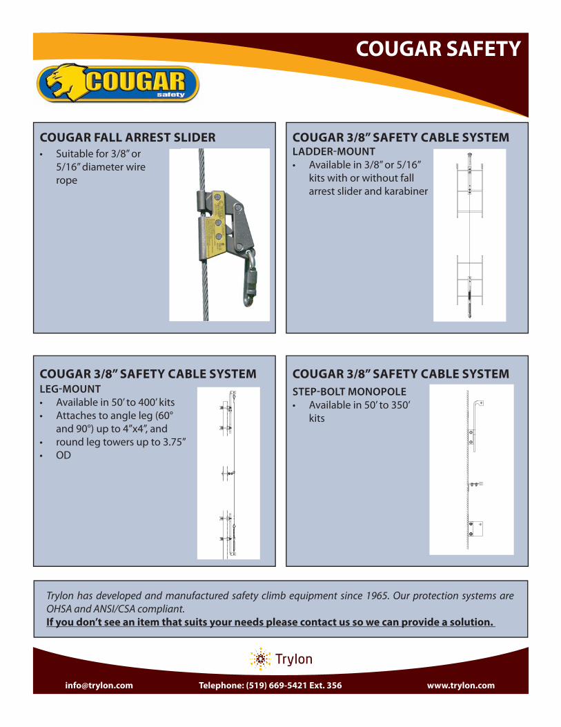
Trylon has developed and manufactured safety climb equipment since 1965. Our protection systems are OHSA and ANSI/CSA compliant. If you don’t see an item that suits your needs please contact us so we can provide a solution.
COUGAR 3/8” SAFETY CABLE SYSTEMLADDER-MOUNT
• Available in 3/8” or 5/16” kits with or without fall arrest slider and karabiner
COUGAR FALL ARREST SLIDER
COUGAR 3/8” SAFETY CABLE SYSTEM
• Suitable for 3/8” or 5/16” diameter wire rope
LEG-MOUNT
• Available in 50’ to 400’ kits• Attaches to angle leg (60°
and 90°) up to 4”x4”, and• round leg towers up to 3.75”• OD
COUGAR 3/8” SAFETY CABLE SYSTEM
STEP-BOLT MONOPOLE
• Available in 50’ to 350’ kits

TRYLON®21 South Field Drive, Elmira, ON N3B 0A6
Phone: (519) 669-5421Fax: (519) 669-8912
www.trylon.com [email protected]
TM, ®, ©, LOGOS, STYLIZED NAMES ARE TRADEMARKS OF TRYLON MANUFACTURING COMPANY LTD. © 2015 PRINTED IN CANADA
www.trylon.com