stonelaw high engineering science homework s4 1 1. describe some of the advantages of using...
TRANSCRIPT
Stonelaw High Engineering Science
Homework S4
Stonelaw High Faculty of Home Economics & Technical Education
2
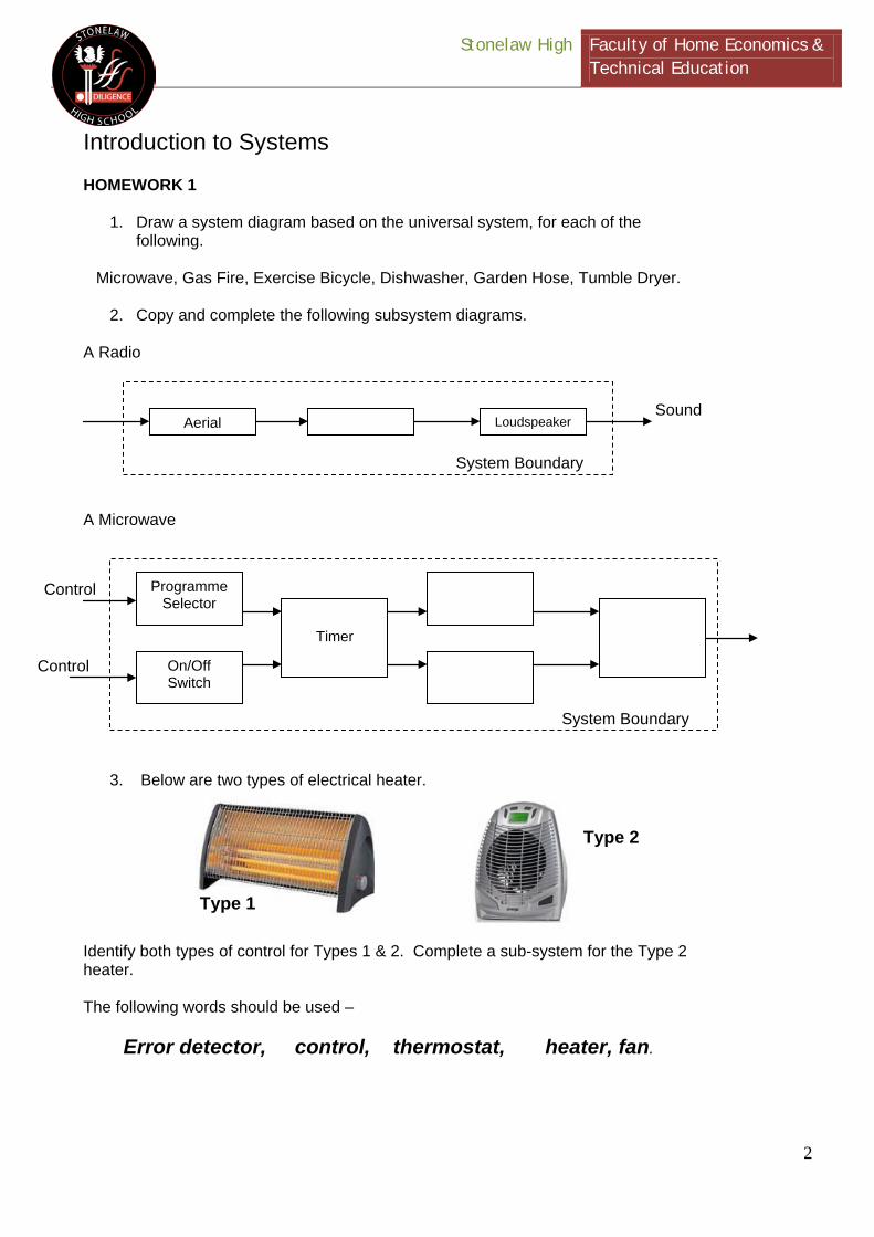
Introduction to Systems HOMEWORK 1
1. Draw a system diagram based on the universal system, for each of the following.
Microwave, Gas Fire, Exercise Bicycle, Dishwasher, Garden Hose, Tumble Dryer.
2. Copy and complete the following subsystem diagrams.
A Radio A Microwave
3. Below are two types of electrical heater.
Identify both types of control for Types 1 & 2. Complete a sub-system for the Type 2 heater. The following words should be used –
Error detector, control, thermostat, heater, fan.
Aerial Loudspeaker
System Boundary
Sound
Timer
System Boundary
Control
Control
Programme Selector
On/Off Switch
Type 1
Type 2

Stonelaw High Faculty of Home Economics & Technical Education
3
4. An office air conditioning unit automatically switches on to provided cool air when the temperature rises above the preset level.
(a) Copy and complete the systems diagram below.
(b) State the name of X.
(c) Describe the difference between manual and automatic control.
Set Temperature Level Cool
Air

Stonelaw High Faculty of Home Economics & Technical Education
4
Homework 2
1. A control diagram for a car’s cruise control is shown below.
(a) What type of control is used in this system? (1) (b) Name component A and describe its function and operation in this system. (4) (c) Describe how the complete speed control system operates. (6)
2. A vacuum cleaner and electric iron are shown below.
(a) Draw a control diagram for the vacuum cleaner. (3)
(b) Draw a control diagram for the iron. (4)
(c) Name the type of control used in each of these items. (2)
Stonelaw High Faculty of Home Economics & Technical Education
5
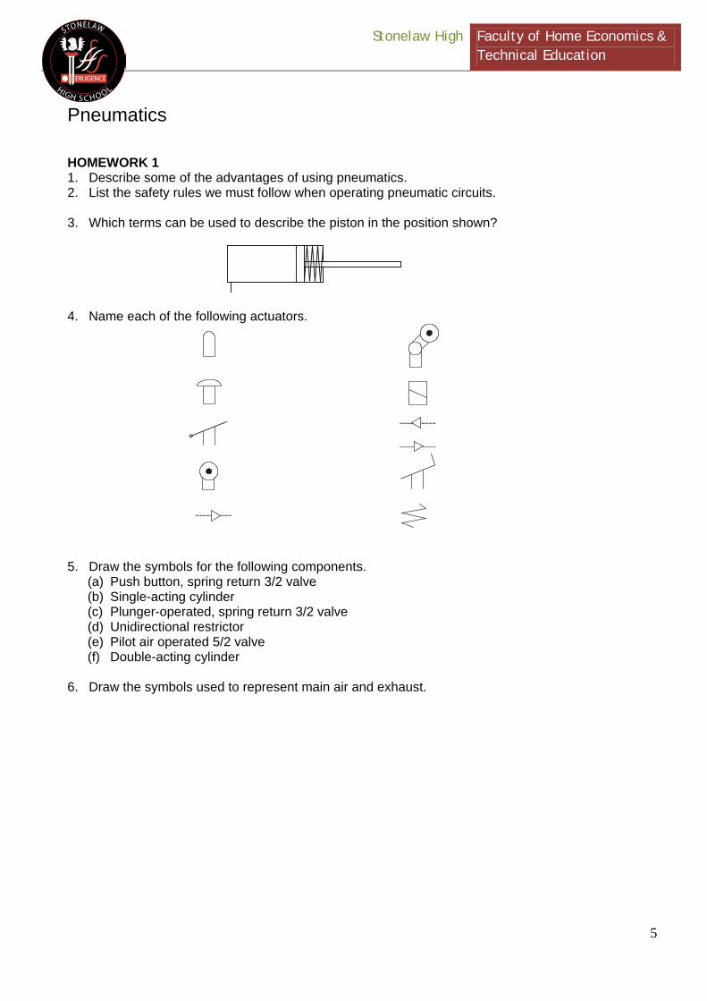
Pneumatics
HOMEWORK 1 1. Describe some of the advantages of using pneumatics. 2. List the safety rules we must follow when operating pneumatic circuits. 3. Which terms can be used to describe the piston in the position shown?
4. Name each of the following actuators.
5. Draw the symbols for the following components.
(a) Push button, spring return 3/2 valve (b) Single-acting cylinder (c) Plunger-operated, spring return 3/2 valve (d) Unidirectional restrictor (e) Pilot air operated 5/2 valve (f) Double-acting cylinder
6. Draw the symbols used to represent main air and exhaust.

Stonelaw High Faculty of Home Economics & Technical Education
6
Homework 2 1. The diagrams below have a basic fault. Identify this fault and then redraw the
diagram properly.
2. A circuit allows a door to be opened by pressing either valve A or valve B. What
type of control is this?
3. Draw the truth table for this type of circuit.
4. How can AND Control improve safety on a production line?
5. Draw a pneumatic circuit that would demonstrate AND Control. Homework 3 1. What is the difference between a restrictor and a unidirectional restrictor?
2. Why do we restrict the exhaust air from a cylinder rather than the air entering the
cylinder?
3. Name the components used to create a time delay. Draw a diagram to show how
they are connected together.
4. How can we change the length of a delay?
5. Describe the difference between a T-piece and a shuttle valve. You may use
sketches to help.
6. Name the following components and describe what they are used for.
a
b c
Valve A Valve B
(a) (b)

Stonelaw High Faculty of Home Economics & Technical Education
7
Homework 4 1. What name is given to the movement produced by an automatic circuit?
2. What is the difference between a semi-automatic and a fully automatic circuit?
3. Explain why the force produced by the instroke of a double-acting cylinder is less
than the outstroke.
4. Safety barriers on a fairground ride are held in place by pneumatic cylinders.
Which type of cylinder would you recommend? Describe the reasons for your choice.
5. A furniture manufacturer uses pneumatics to test wear and tear on drawer guides
in a kitchen unit. A double-acting cylinder is used to constantly open and close the drawer, and the runners are checked regularly. The following pneumatic circuits have been designed to carry out the same task. Describe how each circuit works and choose the circuit that you think would best perform the task. Give reasons for your choice.
DRAWER GUIDES
KITCHEN UNIT
DRAWER
PISTON MOVEMENT
X
DRAWER GUIDES
KITCHEN UNIT
DRAWER
PISTON MOVEMENT
MICRO-SWITCH
12V
12V
Stonelaw High Faculty of Home Economics & Technical Education
8
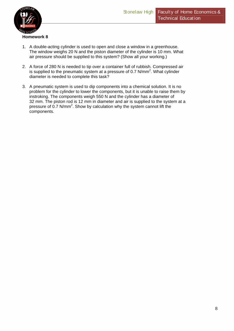
Homework 8 1. A double-acting cylinder is used to open and close a window in a greenhouse.
The window weighs 20 N and the piston diameter of the cylinder is 10 mm. What air pressure should be supplied to this system? (Show all your working.)
2. A force of 280 N is needed to tip over a container full of rubbish. Compressed air
is supplied to the pneumatic system at a pressure of 0.7 N/mm2. What cylinder diameter is needed to complete this task?
3. A pneumatic system is used to dip components into a chemical solution. It is no
problem for the cylinder to lower the components, but it is unable to raise them by instroking. The components weigh 550 N and the cylinder has a diameter of 32 mm. The piston rod is 12 mm in diameter and air is supplied to the system at a pressure of 0.7 N/mm2. Show by calculation why the system cannot lift the components.

Stonelaw High Faculty of Home Economics & Technical Education
9
End-of-Topic Revision Hot plastic sheets are moulded into cups using a former attached to the end of a double-acting cylinder. An operator starts the process by pressing a button, but the cylinder should instroke automatically. Before this happens, there should be a delay to allow the plastic sheet to cool and set in shape. A partly completed diagram is shown.
HOT PLASTIC SHEET
(a) Complete the missing piping.
(b) State the full name of each of the pneumatic components marked on the diagram.
(c) Using appropriate terminology, explain how the circuit works.
(d) The cylinder instrokes so quickly that sometimes the cup gets stuck onto the former. Name the component that could be used to reduce the speed of the cylinder.
(e) The component named in your answer to (d) can be inserted in the circuit shown above so that the cylinder instrokes slowly. Add this component to the circuit diagram at the appropriate point.
(f) Describe two ways of changing the length of time delay.
(g) It requires a force of 16 N to press the plastic sheet into shape. What air pressure is required if the diameter of the piston is 10 mm. (Show all working and units.)
[Pressure = Force/Area, Area = πr2 = πd2/4]

Stonelaw High Faculty of Home Economics & Technical Education
10
Jib
Tie
120°
30°
Mechanisms and Structures Vectors 1 1. The small crane, shown below, is used in a boating marina to lift sailing boats weighing about 400 kN. Find the forces in the jib and the tie.
2. A rope running over a pulley makes an included angle of 85 degrees. If the tension in the rope is 450 N, what is the resultant force?
3. When a girder was being moved into position it was found that a force system as shown below was required. Find the magnitude and direction of the force X.
450
450
Effort
Load
X N
100 N
250 N
Stonelaw High Faculty of Home Economics & Technical Education
11
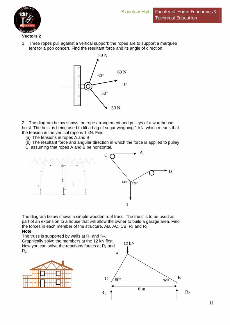
Vectors 2 1. Three ropes pull against a vertical support; the ropes are to support a marquee
tent for a pop concert. Find the resultant force and its angle of direction.
2. The diagram below shows the rope arrangement and pulleys of a warehouse hoist. The hoist is being used to lift a bag of sugar weighing 1 kN, which means that the tension in the vertical rope is 1 kN. Find:
(a) The tensions in ropes A and B. (b) The resultant force and angular direction in which the force is applied to pulley C, assuming that ropes A and B be horizontal.
The diagram below shows a simple wooden roof truss. The truss is to be used as part of an extension to a house that will allow the owner to build a garage area. Find the forces in each member of the structure. AB, AC, CB, R1 and R2. Note: The truss is supported by walls at R1 and R2. Graphically solve the members at the 12 kN first. Now you can solve the reactions forces at R1 and R2.
50 N
60 N
30 N
60°
50°
10°
140°
120°
1
A
B
C
R1
R2
A
B
C
6 m
60°
30°
12 kN

Stonelaw High Faculty of Home Economics & Technical Education
12
Levers 1 1. A lever system is shown below. Draw out and label the following parts.
Lever fulcrum load effort 2. With the aid of sketches, describe a practical use for each of the three orders of lever. 3. Sketch a bell crank lever and a cantilever. 4. Complete the following sentence - Bell cranks can be used to.. 5. Levers give you a force ratio. What does this mean? 6. Find the distance away from the pivot for the 10 N effort to balance the system.
3 m
DISTANCE
50 N
10 N

Stonelaw High Faculty of Home Economics & Technical Education
13
Levers 2 1. Find the size of the effort to balance the lever. 2. Determine the size of the effort to balance the lever. 3. A steel bar is used as a 2nd order lever to overcome the weight of a 49 N load attached to the bar at a point 300 mm from the fulcrum. The effort is applied at a point 1.2 m from the fulcrum. Assuming no friction, what is the force ratio of this lever if: (a) The mass of the bar is neglected. (b) The mass of the bar is 68.6 N (c) And what is the efficiency in each case. 4. The effort required to lift a load of 1500 N using a crane was found to be 102 N. The same crane required an effort of 40 N to raise a load 500 N. For a distance ratio of 25: (a) Determine the effort required to raise a load of 1250 N. (b) What is the efficiency at this load?
49 N
300 mm
1.2 m
EFFORT
2 m 18 kN
6 m EFFORT
2 m
100 N
10 m
EFFORT

Stonelaw High Faculty of Home Economics & Technical Education
14
Beams and Reactions 1. A weightlifter’s bench supports the weights as shown. The weights are positioned equally from the centre at three metres and the weight at each side of the support is 200 N. (a) Complete a free-body diagram with arrows to show the downward and reaction forces. (b) Show your calculations for the reaction forces. (c) Which type of force is affecting the vertical supports?
2. The free-body diagram below shows part of a structural support in an electricity pylon. The support ABCD is seven metres long and is simply supported at A and D and is loaded as indicated. Determine the reactions. 3. The free-body diagram of a horizontal concrete beam is shown below. The concrete structure has to support vertical columns with the downward loads. Calculate the reactions at R1 and R2. 4. 5. Determine the reactions for the beam support shown.
10 kN
4 m
R2
R1
2 kN
5
2
2
3 m
A
B
C
D
10 kN
8 kN
2 m
2 m
3 m
10 kN
500 N
2
2.5
4 m
5 m
6 kN
R1
R2

Stonelaw High Faculty of Home Economics & Technical Education
15
5. A bridge spanning a ravine is shown below. A number of forces are applied to the
structure, which consists of five equilateral triangles for structural stability. Calculate the end reactions where the bridge is supported at A and B.
6. A free-body diagram of an overhanging balcony area is shown below. The
distance to the left of the reaction allows for structural support.
(a) Find the reaction (b) Find the distance X
7. The vehicle shown below is used to transport unusual loads. In this case the
transporter is transferring a racing car to a motor racing event. Calculate the reaction force RA on the front pivot due to the load of the transporter and the racing car.
(a) Draw the free-body diagram (b) Calculate the reaction force (RA) at the swivel joint at the cab.
A
50
30 kN 3
3
3 m
3 kN
1
2
1
2 kN
X m
RA
35
2.5 m
3.5

Stonelaw High Faculty of Home Economics & Technical Education
16
DRIVER GEAR A DRIVEN GEAR B
SHAFT A SHAFT B
15 TEETH 25 TEETH 45 TEETH
DRIVER GEAR A DRIVEN GEAR B
SHAFT A SHAFT B
15 TEETH 25 TEETH 45 TEETH
E
F
Gears 1 1. A simple gear train is shown. The driver gear A has 20 teeth. When shaft A is rotated 10 times, shaft B rotates five times.
(a) How many teeth has gear B? (b) What is the gear ratio of the system? (c) If shaft A rotates at 60 rpm, at what speed does shaft B rotate? (d) If shaft A rotates anti-clockwise, in which direction does shaft B rotate?
2. What is the movement ratio of the gear system shown below? 3. In the simple gear train shown below, driver A
has 20 teeth. When shaft A rotates 10 times, shaft B rotates five times. (a) What is the movement ratio of the system? (b) How many teeth does gear B have? (c) If shaft A rotates at 600 rpm, at what speed will shaft B turn? (d) If A rotates clockwise, what direction will B rotate?
4. The names following are all associated with gears. Pick two and explain what they
mean. Simple gear train, mesh, idler, compound gear train 5. What is the gear ratio of the transmission system
shown? If gear E rotates clockwise, in which direction will gear F rotate?
6. The black box system below contains a simple gear train. (a) When shaft G is rotated 60 times, shaft H rotates
40 times. Using two gears chosen from those listed above sketch the transmission system that the box contains.
(b) Do the same for the shaft G being rotated 10 times, and shaft H rotated eight times. SHAFT
SHAFT H
GEARS: 35
30
25
20

Stonelaw High Faculty of Home Economics & Technical Education
17
DRIVER 1200 REVST 120
T 60
DRIVENT 180
DRIVER 200 REVST 10
T 100
T 20
DRIVENT 60
DRIVER GEAR19 TEETH
57 TEETH 57 TEETH
19 TEETHSHAFT C SHAFT D
Gears 2 1. What is the name of the transmission system shown below?
a) What is the gear ratio of the system? b) If shaft C rotates at 36 rpm, at what speed will shaft D rotate?
2. A compound gear train consists of a driver gear A having 40 teeth, engaging with gear B, having 160 teeth. Attached to the same shaft as B, gear C has 48 teeth and meshes with gear D on the output shaft, having 96 teeth. (a) Draw a diagram to show the arrangement. (b) Determine the movement ratio of the gear train. 3. In the compound train shown below wheel A is rotating at 100 rpm. If the numbers of teeth in the gear wheels A, B, C and D are 25, 50, 25, and 50 respectively, determine the speed of rotation of wheel D. 4. Calculate the output speed in the two examples of gear systems. 5. Four parallel shafts A, B, C, and D are connected by a simple gear train. The number of teeth in each wheel is as follows.
A = 40 B = 25 C = 30 D = 60
If wheel A is rotating at 200 rpm in a clockwise direction, determine the speed and direction of rotation of the other gear wheels.
A
B
C
D

Stonelaw High Faculty of Home Economics & Technical Education
18
6. The compound gear train shown below is driven by a motor that runs at 750 rpm.
Calculate: (a) The output shaft speed. (b) The ratio of the motor spindle speed to the output speed.
7. A motorised winch is shown below. The motor runs at 1350 rpm and the drum is to rotate at 54 rpm. Find the number of teeth that the motor drive gear must have to satisfy this requirement.
8. A compound gear train consists of an input gear A with 30 teeth that meshes with gear B having 60 teeth. Gear C is attached to gear B and has 30 teeth. Gear D is in mesh with gear C. Determine the number of teeth in gear D to give a movement ratio between A and D of 5.33.
9. Two gear wheels A and B are in mesh. Wheel A has 20 teeth and wheel B 60
teeth. Attached to wheel A is a pulley of diameter 30 mm and to wheel B a pulley of diameter 120 mm. If an effort of 50 N is applied through a rope wrapped around pulley B, what load attached to a rope wrapped around pulley A would be moved? Assume the machine to be 100 per cent efficient.
MOTOR
DRUM
60 t
36 t
90 t
20 t
100 t
MOTO
A
B
C
D
tA = 20 tB = 50 tC = 30 tC = 90

Stonelaw High Faculty of Home Economics & Technical Education
19
Torque 1. Determine the torque when a pulley wheel of diameter 300 mm has a force of 80 N applied at the rim. 2. Determine the force applied tangentially to a bar of a screwjack at a radius of 800 mm, if the torque required is 600 N/m. 3. A constant force of 150 N is applied at a tangent to a wheel of diameter 140 mm. Determine the work done in 12 revolutions of the wheel. Your answer should be in joules and watt-hours. 4. Calculate the torque developed by a motor whose spindle is rotating at 1000 rpm and developing a power of 2.5 kW. 5. An electric motor develops a power of 3.75 kW and a torque of 12.5 N/m. Determine the speed of rotation of the motor in rpm. 6. A pulley is 600 mm in diameter and the difference in tension on the two sides of the driving belt is 1.5 kN. If the speed of the pulley is 500 rpm, determine:
(a) the torque developed (b) the work done in three minutes.
7. A 15 kW motor is driving a shaft at 1150 rpm by means of pulley wheels and a belt. The tensions in the belt on each side of the driver pulley are 400 N and 50 N and the diameters of the driver and driven pulley wheels are 500 mm and 750 mm respectively. Calculate:
(a) the power output (b) the efficiency of the motor.

Stonelaw High Faculty of Home Economics & Technical Education
20
Ø 100
Ø 400
DRIVER200 REVS
DRIVENBelt drives 1. A belt and pulley system is shown below.
(a) Calculate the output speed of the driven pulley. (b) Describe one advantage of a belt and pulley over other drive systems. (c) Show with a sketch how a belt and pulley system could be joined to make the input and output turn in different directions. Label the driver (input) and the driven (output).
2. Write down why/where you would use the following types of drive belts.
V-belt Linked belt Round belt Toothed belt
3. Determine the speed of the pulley B in this belt drive if pulley A rotates at 150 rpm.
4. The diagram shows a stepped-cone pulley system as used on some pillar drills.
By changing the position of the V-belt, three different shaft speeds can be obtained.
(a) In which position must the belt be engaged to provide the highest drill speed? (b) If the drive motor runs at 1400 rpm, what is the maximum drill speed? (c) What is the lowest speed at which the drill will run? 5. Determine the speed of the pulley B in this belt drive if pulley A rotates at 150
rpm.
Ø 10
Ø 8
Ø 14
Ø 4
SPINDL
CHUCK
DRILL
DRIVE MOTOR
V-
STEPPED-CONE
20 t
32 t
A
B

Stonelaw High Faculty of Home Economics & Technical Education
21
DRIVER DRIVEN
100 REVS
T 60 T 40
DRIVER DRIVEN
500 REVS
T 200 T 120
DRIVER DRIVEN
4 REVS
T 100 T 400
DRIVER DRIVEN
90 REVS
T 20 T 60
a b
c d
Chain drives 1. A chain and sprocket is shown below. Copy and label the following parts.
Driver driven chain sprockets 2. Describe one advantage and one disadvantage in using a chain and sprocket system. 3. Write down the formula for movement ratio. 4. Determine the speed of sprocket B in this chain drive if sprocket A rotates at 150 rpm. 5. Four chain drive systems are shown below. Calculate the output speed for each.

Stonelaw High Faculty of Home Economics & Technical Education
22
Conversion of movement 1. Copy out and name the four types of motion that are illustrated below, and give an example of each in action.
2. The items shown below convert motion. Name the device and conversion that takes place.

Stonelaw High Faculty of Home Economics & Technical Education
23
CONNECTINGROD
CRANK
NEEDLE
GUIDES
RECIPROCATINGMOTION
Crank and slider 1. Copy and complete the following sentence. Crank slider mechanisms involve changes between _______________ and _________________ motion. 2. The diagram shows a power hacksaw similar to the one used in school workshops. The diagram outlines the crank and slider mechanism that it uses. If the stroke of the hacksaw blade is 120 mm, what is the length of crank? 3. The following diagram shows a domestic sewing machine. The diagram shows the crank and slider mechanism that is used to produce reciprocating motion at the needle. At its slowest operating speed, the needle moves down 120 times per minute. At what speed does the crank rotate?
CONNECTING ROD GUIDE SLIDER
CRANK
STROKE = 120 mm

Stonelaw High Faculty of Home Economics & Technical Education
24
a b c
R 60
R 20
R 20
0R
150
Worm and wheel, rack and pinion, gears, etc. 1. Three different mechanisms are shown below. Name each and describe the change in movement produced. Example: gear train = rotational to rotational motion.
2. Below is a mechanical device that allows rotation only in one direction.
(a) Name the device. (b) Copy out the diagram and using an arrow on the diagram show the direction in which the device will turn.
3. A cam and follower is shown below. (a) Copy out and label the following parts: cam, follower, stroke (b) Describe the change in motion that the cam and follower produces. (c) What is the purpose of the spring? 4. In the two examples below, how far will the rod move? 5. A single start worm and wheel similar to the one shown below has an effort wheel
of 140 mm diameter, and a load drum diameter of 125 mm. If the worm has 40 teeth calculate: (a) The movement ratio for the machine. (b) The effort required to raise a load of 390 N if the efficiency of the machine is 67 per cent.
Stonelaw High Faculty of Home Economics & Technical Education
Homework Booklet Stonelaw High School
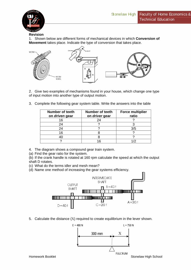
Revision 1. Shown below are different forms of mechanical devices in which Conversion of Movement takes place. Indicate the type of conversion that takes place.
2. Give two examples of mechanisms found in your house, which change one type of input motion into another type of output motion. 3. Complete the following gear system table. Write the answers into the table
Number of teeth on driven gear
Number of teeth on driver gear
Force multiplier ratio
16 24 ? 24 ? 3 24 ? 3/5 16 8 ? 40 8 ? ? 16 1/2
4. The diagram shows a compound gear train system. (a) Find the gear ratio for the system. (b) If the crank handle is rotated at 160 rpm calculate the speed at which the output shaft D rotates. (c) What do the terms idler and mesh mean? (d) Name one method of increasing the gear systems efficiency. 5. Calculate the distance (Χ) required to create equilibrium in the lever shown.
E = 480 N L = 750 N
FULCRUM
300 mm Χ

Stonelaw High Faculty of Home Economics & Technical Education
Homework Booklet Stonelaw High School
6. The diagram shows a transporter carrying a heavy machine to a factory. Calculate the reaction force R1 with the combined weight of the machine casting 25 kN and the trailer 4 kN of the transporter. 7. Safety in driving is very important. Explain in mechanical terms how a car safety belt could operate in aiding safe driving. Sketch a suitable mechanical device. 8. An exploded view of a split bearing is shown.
(a) What function does the bearing have? (b) Explain why it is split into two parts.
9. A motor drives a spindle using pulleys and a vee-belt as shown below. If the motor runs at 1000 rpm, what three speeds will be available at the output shaft?
R1 1 5 m 2.5 m
CAP
TOP SHELL
OIL GROOVE BOTTOM SHELL
Ø 100 mm Ø140 mm
OUTPUT
Ø 80 mm

Stonelaw High Faculty of Home Economics & Technical Education
Homework Booklet Stonelaw High School
10. A section of a suspension bridge is to be lifted into place using a tower crane on a floating barge. The current flow in the river causes the barge to sway, creating difficulty in aligning the box section of bridge. Three boats are used to apply separate forces to the barge to maintain stability and allow the section of bridge to be fitted. The diagram below shows the forces and angles applied by the tugs to the crane barge. Find the resultant force and its single angle of direction. 11. The effective pull on a belt is 400 N when driving a 180 mm diameter pulley. The speed of rotation is 320 rpm. Calculate: (a) The power generated without any belt slippage. (b) The power generated with 5 per cent slippage. 12. Explain the following terms.
• Oscillating motion • Friction • Jockey wheel • Free-body diagram
2500
1500
2000 N
70
45°
10°