stoptite manual #4111-0015 nov2009:pstop manual … ignite spills or leaks near the work area....
TRANSCRIPT

STOP -TITE®
Truck Restraint
Owner’s/User’s Manual
MCGUIRE • DIVISION OF SYSTEMS, INC. • W194 N11481 McCormick Drive • Germantown, WI 53022
800.624.8473 • fax: 262.255.9399 • www.wbmcguire.com • [email protected]
Printed in U.S.A.
Copyright © 2008
Manual No. 4111-0015
November 2009
PageSafetyRecognize Safety Information . . . . . . . . . . . . . . . . . . . . . . . . . . . . . . . 1General Operational Safety Precautions . . . . . . . . . . . . . . . . . . . . . . 1Operational Safety Precautions . . . . . . . . . . . . . . . . . . . . . . . . . . . . . 2Maintenance Safety Precautions . . . . . . . . . . . . . . . . . . . . . . . . . . . . 4
IntroductionGeneral Information . . . . . . . . . . . . . . . . . . . . . . . . . . . . . . . . . . . . . . . 5
InstallationInstall Control Panel and Wiring . . . . . . . . . . . . . . . . . . . . . . . . . . . . 6
OperationOperating Instructions . . . . . . . . . . . . . . . . . . . . . . . . . . . . . . . . . . . . 11
TroubleshootingTroubleshooting . . . . . . . . . . . . . . . . . . . . . . . . . . . . . . . . . . . . . . . . . 13
MaintenancePeriodic Maintenance . . . . . . . . . . . . . . . . . . . . . . . . . . . . . . . . . . . . . 18
PartsMechanical STOP-TITE® Components . . . . . . . . . . . . . . . . . . . . . . . . 20Hydraulic STOP-TITE® Components . . . . . . . . . . . . . . . . . . . . . . . . . 22Powerpack Assembly . . . . . . . . . . . . . . . . . . . . . . . . . . . . . . . . . . . . . 24Outside Signs . . . . . . . . . . . . . . . . . . . . . . . . . . . . . . . . . . . . . . . . . . . 26Outside Light Assembly . . . . . . . . . . . . . . . . . . . . . . . . . . . . . . . . . . 27
MiscellaneousCustomer Information . . . . . . . . . . . . . . . . . . . . . . . . . . . . . . . . . . . . 29Warranty . . . . . . . . . . . . . . . . . . . . . . . . . . . . . . . . . . . . . . . . Back Cover
Table of Contents
4111-0015 — November 2009
1
SAFETY
4111-0015 — November 2009
Recognize Safety Information
Read and understand the operating instructions andbecome thoroughly familiar with the equipment andits controls before operating the dock leveler or truckrestraint.
Never operate a dock leveler or truck restraint while asafety device or guard is removed or disconnected.
Never remove DANGER, WARNING, or CAUTIONsigns or decals on the equipment unless replacingthem.
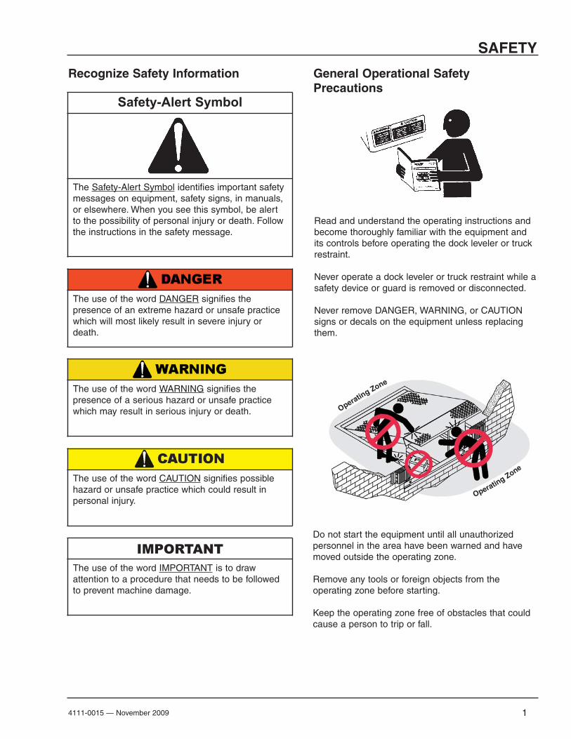
General Operational SafetyPrecautions
Do not start the equipment until all unauthorizedpersonnel in the area have been warned and havemoved outside the operating zone.
Remove any tools or foreign objects from theoperating zone before starting.
Keep the operating zone free of obstacles that couldcause a person to trip or fall.
The use of the word DANGER signifies thepresence of an extreme hazard or unsafe practicewhich will most likely result in severe injury ordeath.
Safety-Alert Symbol
The Safety-Alert Symbol identifies important safetymessages on equipment, safety signs, in manuals,or elsewhere. When you see this symbol, be alertto the possibility of personal injury or death. Followthe instructions in the safety message.
The use of the word WARNING signifies thepresence of a serious hazard or unsafe practicewhich may result in serious injury or death.
IMPORTANTThe use of the word IMPORTANT is to drawattention to a procedure that needs to be followedto prevent machine damage.
The use of the word CAUTION signifies possiblehazard or unsafe practice which could result inpersonal injury.
Operating Zone
Operating Zone

2
SAFETY
4111-0015 — November 2009
Learn the safe way to operate this equipment. Read and understand the
manufacturer's instructions. If you have any questions, ask your supervisor.
Operational Safety Precautions
Stay clear of dock leveling device when freightcarrier is entering or leaving area.
Do not move or use the dock leveling device ifanyone is under or in front of it.
Keep hands and feet clear of pinch points. Avoidputting any part of your body near moving parts.
Chock/restrain all freight carriers. Never removethe wheel chocks until loading or unloading isfinished and truck driver has been givenpermission to drive away.
Do not use a broken or damage dock levelingdevice. Make sure proper service andmaintenance procedures have been performedbefore using.
Make sure lip overlaps onto trailer at least 4 in.(102 mm).
Keep a safe distance from both side edges.

3
SAFETY
4111-0015 — November 2009
Do not use dock leveling device if freight carrier istoo high or too low.
Do not overload the dock leveling device.
Do not operate any equipment while under theinfluence of alcohol or drugs.
Do not leave equipment or material unattended ondock leveling device.
4
SAFETY
4111-0015 — November 2009
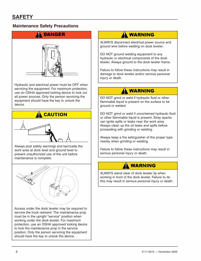
Maintenance Safety Precautions
ALWAYS disconnect electrical power source andground wire before welding on dock leveler.
DO NOT ground welding equipment to anyhydraulic or electrical components of the dockleveler. Always ground to the dock leveler frame.
Failure to follow these instructions may result indamage to dock leveler and/or serious personalinjury or death.
ALWAYS stand clear of dock leveler lip whenworking in front of the dock leveler. Failure to dothis may result in serious personal injury or death.
DO NOT grind or weld if hydraulic fluid or otherflammable liquid is present on the surface to beground or welded
DO NOT grind or weld if uncontained hydraulic fluidor other flammable liquid is present. Stray sparkscan ignite spills or leaks near the work area.Always clean up the oil leaks and spills beforeproceeding with grinding or welding.
Always keep a fire extinguisher of the proper typenearby when grinding or welding.
Failure to follow these instructions may result inserious personal injury or death.
Always post safety warnings and barricade thework area at dock level and ground level toprevent unauthorized use of the unit beforemaintenance is complete.
Hydraulic and electrical power must be OFF whenservicing the equipment. For maximum protection,use an OSHA approved locking device to lock outall power sources. Only the person servicing theequipment should have the key to unlock thedevice.
Access under the dock leveler may be required toservice the truck restraint. The maintenance propmust be in the upright "service" position whenworking under the dock leveler. For maximumprotection, use an OSHA approved locking deviceto lock the maintenance prop in the serviceposition. Only the person servicing the equipmentshould have the key to unlock the device.
54111-0015 — November 2009
INTRODUCTION
General Information
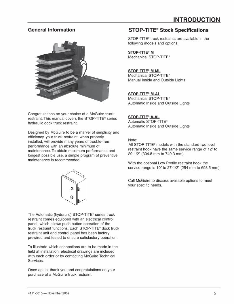
STOP-TITE® truck restraints are available in thefollowing models and options:
STOP-TITE® MMechanical STOP-TITER
STOP-TITE® M-MLMechanical STOP-TITER
Manual Inside and Outside Lights
STOP-TITE® M-ALMechanical STOP-TITER
Automatic Inside and Outside Lights
STOP-TITE® A-ALAutomatic STOP-TITER
Automatic Inside and Outside Lights
Note: All STOP-TITE® models with the standard two levelrestraint hook have the same service range of 12” to29-1/2” (304.8 mm to 749.3 mm)
With the optional Low Profile restraint hook theservice range is 10” to 27-1/2” (254 mm to 698.5 mm)
Call McGuire to discuss available options to meetyour specific needs.
The Automatic (hydraulic) STOP-TITER series truckrestraint comes equipped with an electrical controlpanel, which allows push button operation of thetruck restraint functions. Each STOP-TITER dock truckrestraint unit and control panel has been factoryprewired and tested to ensure satisfactory operation.
To illustrate which connections are to be made in thefield at installation, electrical drawings are includedwith each order or by contacting McGuire TechnicalServices.
Once again, thank you and congratulations on yourpurchase of a McGuire truck restraint.
STOP-TITE® Stock Specifications
Congratulations on your choice of a McGuire truckrestraint. This manual covers the STOP-TITER serieshydraulic dock truck restraint.
Designed by McGuire to be a marvel of simplicity andefficiency, your truck restraint, when properlyinstalled, will provide many years of trouble-freeperformance with an absolute minimum ofmaintenance. To obtain maximum performance andlongest possible use, a simple program of preventivemaintenance is recommended.

6 4111-0015 — November 2009
INSTALLATION DETAILS-AUTOMATIC STOP-TITE®
LEVEL
11”
SECTION "A-A"
A
A712 89 1414 6
5
4 1
3
11 10
CONNECT TO BASE END OF RELEASE CYL.BC
DESCRIPTIONNOTE
RC CONNECT TO ROD END OF RELEASE CYL.
Capacitor Wiring Detail
Mot
or B
lue
Mot
or R
ed
6
2
13
R.V. SET @
HYDRAULIC SCHEMATIC
105M 650 PSI
RC BC
1 1 1431-0011 Connector - 2-Screw 3/8
2 3 1431-0086 Insulated Terminial 16-14 AWG
3 2 2101-0017 Hex Head Capscrew 3/8-16 UNC X 1
4 2 2101-0140 Lock Washer 3/8
5 1 2751-0016 Cover - J-Box 4 X 4
6 1 3051-0058 Capacitor - Motor Start 64-77mF - 330V
7 2 6431-0001 Grommet 1-3/8 OD X 3/4 ID
8 2 9301-0164 Fitting Conn Str Thrd #4 ORB X #4 JIC
9 1 9395-0401 Powerpac - STOP-TITE® 1PH - 115V - 1/4 HP - 1 GPM
10 1 9391-0039 Cover - STOP-TITE® B CAD
11 1 9393-0025 Powerpac Mounting Weldment B CAD
12 2 9904-0097 Hyd Hose Assy - 1/4"100R1 X 24.00 #4 JICF SWIVEL BOTH ENDS
13 1 R513-0050 Wire 16 GA RED X 5.00"
14 2 R598-0090 Split Flex Conduit 1/4" X 9.00"
BILL OF MATERIAL
QTYITEM DESCRIPTIONPART NO. SIZE
STOP-TITE® Overview
STOP-TITE Powerpack
Powerpack Location Options
For comprehensive installation instructions of the Automatic
STOP-TITE (STOP-TITE ) read and understand the Installation
and Operation Manual.
AAL
McGuire.
McGuire
Coordinate powerpack location and hose length for proper placement.
Dock FaceAppropriate location when the likelihood of flooding, snow removal and damage from trailer/trucks is minimal.
Under The Dock LevelerWhen under the dock location is used, make certain to locate the powerpack where leveler will not interfere in below dock conditions. The routing of hydraulic and electrical lines from the powerpack to the restraint are best placed through min. 3” PVC (hydraulic) and 3/4” conduit (electricl) chase during pit construction.
Inside BuildingLocate powerpck to minimize obstruction potential. Hydraulic and electrical lines from the Powerpack to the restraint are best placed through min. 3” PVC (hydraulic) and 3/4” (electrical) chase during pit construction.
AAL
Conduit, flexible or rigid, must be connected between the limit switch on the restraint and the powerpack. Wiring to and from the restraint must be limited to restraint wires only. Do not run high voltage lines through the same conduit as restraint wires. Conduit and associated hardware to complete wiring and mounting of powerpack are to be supplied by others.

74111-0015 — November 2009
INSTALLATION DETAILS-AUTOMATIC STOP-TITE®
Low Pit Floor (Distance from pit floor to drive under 24”)
Cantilevered Dock (For bumper projection >4” or cantilevered dock or Edge-of-Dock leveler)
Driveway Mount (Recommended when dock face is unsuitable for STOP-TITE Mounting)
Anchor pit floor mounting plate (minimum 3/8” x 20”W x 8”D)(Part #9414-0056) with four (4) (3/4” x 5 1/4” min.) wedge anchors.Weld mounting plate to curb steel and back plate of STOP-TITE with a continuous 1/4” fillet weld. Anchor back plate of STOP-TITE to dock face with a minimum or (4) 3/4” x 5 1/4” wedge anchors (Kit#2103-0003).
Trim or cut front frame member when necessary to allow for pit floor mounting plate.
To determine size offset required, take total effective bumper projection (bumper size plus any cantilever) and subtract 4”.
Offset FormulaDim. A
Bumper ProjectionDim. B
CanteleverOffset
4”
6”
10”
15”
+ Dim B
+ Dim B
+ Dim B
+ Dim B
-4” = Offset
Driveway Mount
Determine offset then proceed with “Driveway Mount” instructions below.
Wall Mount
For filler requirements from 1 1/2” to 7 1/2” use cantilever bracket #9414-0052 and anchor cantilever bracket to the dock face or weld to embedded mounting plate (Part #7953-0119)
For filler requirements for 8 3/4” to 13 3/4” use cantilever bracket #9414-0053 and anchor cantilever bracket to the dock face (3/4” Dia. x 5 1/4” min.)(Kit #2103-0004) or weld to embedded mounting plate (Part #9414-0052).
Driveway mount requires attachment to a concrete drive greater than 8” thick. For asphalt drive, pour 48” x 48” x 8” (min.) concrete pad and include six (6) 3/4” dowels into foundation wall. Then proceed with adhesive anchors or weld plate embed.
Adhesive Anchors Method(Kit #9414-0058)
I n s t a l l t w o ( 2 ) 1 ” D i a . adhesive anchors into 1-1/8” Dia. x 7” deep hole at rear of STOP-TITE.
Install two (2) 3/4” Dia. x 5 1/4” min. wedge anchor at front of STOP-TITE.
If <24”
Drive Embed Method
Weld MethodProperly locate and level the drive embed weld plate (Part #7953-0059) in the drive approach. Observe Cantilever conditions for propepositioning. Weld restraint to embed plate with a continuous 1/4” filet weld.
Bolt on MethodProperly locate and level the drive embed plate (Part #9414-0057) in the drive approach Observe cantilever conditions for proper positioning. Using the bolts included, bolt the restraint to the embed plate.48”
8” min
Concrete Dock Face (Standard Installation)
OptionalEmbed
Plate
Wedge Anchors MethodUsing back plate as a guide, drill six (6) holes for wedge anchors (3/4” x 5 1/4” min.) (Kit #2103-0003)
Wall Embed MethodWeld three sides of STOP-TITE back plate to the optional embed mounting plate (Part #7953-0119) with ten (10) 4” long 1/4” fillet welds.
27”
5 1/4 minimum”
18”
27” 29.5”with prox sensor
24.75”

8 4111-0015 — November 2009
INSTALLATION DETAILS-MECHANICAL STOP-TITE®
STOP-TITE Overview
Optional Light Communication System
For comprehensive
installation instructions of the Manual
STOP-TITE (STOP-TITE ) read and
understand the Installation and Operation
Manual.
M
Mount PowerStopOperating Barbracket on theinterior wall (closestto control panel ifapplicable).
Operating BarPart #5455-0005
Operating Bar BracketPart #0192-0161
STOP-TITE
STOP-TITE
STOP-TITE
STOP-TITESTOP-TITE
STOP-TITE

94111-0015 — November 2009
INSTALLATION DETAILS-MECHANICAL STOP-TITE®
Concrete Dock Face (Standard Installation)
Low Pit Floor (Distance from pit floor to drive under 24”)
Cantilevered Dock (For bumper projection >4” or cantilevered dock or Edge-of-Dock leveler)
Driveway Mount (Recommended when dock face is unsuitable for STOP-TITE) Mounting)
OptionalEmbed
Plate
18”
Wedge Anchors MethodUsing back plate as a guide, drill six (6) holes for wedge anchors (3/4” x 5 1/4” min.) (Kit #2103-0003)
Wall Embed MethodWeld three sides of STOP-TITE back plate to the optional embed mounting plate (Part #7953-0119) with ten (10) 4” long 1/4” fillet welds.
27”
5 1/4 minimum”
Anchor pit floor mounting plate (minimum 3/8” x 20”W x 8”D)(Part #9414-0056) with four (4) (3/4” x 5 1/4” min.) wedge anchors.Weld mounting plate to curb steel and back plate of STOP-TITE with a continuous 1/4” fillet weld. Anchor back plate of STOP-TITE to dock face with a minimum or (4) 3/4” x 5 1/4” wedge anchors (Kit#2103-0003).
Trim or cut front frame member when necessary to allow for pit floor mounting plate.
To determine size offset required, take total effective bumper projection (bumper size plus any cantilever) and subtract 4”.
Offset FormulaDim. A
Bumper ProjectionDim. B
CanteleverOffset
4”
6”
10”
15”
+ Dim B
+ Dim B
+ Dim B
+ Dim B
-4” = Offset
Driveway Mount
Determine offset then proceed with “Driveway Mount” instructions below.
Wall Mount
For filler requirements from 1 1/2” to 7 1/2” use cantilever bracket #9414-0052 and anchor cantilever bracket to the dock face or weld to embedded mounting plate (Part #7953-0119)
For filler requirements for 8 3/4” to 13 3/4” use cantilever bracket #9414-0053 and anchor cantilever bracket to the dock face (3/4” Dia. x 5 1/4” min.)(Kit #2103-0004) or weld to embedded mounting plate (Part #9414-0052).
Driveway mount requires attachment to a concrete drive greater than 8” thick. For asphalt drive, pour 48” x 48” x 8” (min.) concrete pad and include six (6) 3/4” dowels into foundation wall. Then proceed with adhesive anchors or weld plate embed.
Adhesive Anchors Method(Kit #9414-0058)
I n s t a l l t w o ( 2 ) 1 ” D i a . adhesive anchors into 1-1/8” Dia. x 7” deep hole at rear of STOP-TITE.
Install two (2) 3/4” Dia. x 5 1/4” min. wedge anchor at front of STOP-TITE.
If <24”
Drive Embed Method
Weld MethodProperly locate and level the drive embed weld plate (Part #7953-0059) in the drive approach. Observe Cantilever conditions for proper positioning. Weld restraint to embed plate with a continuous 1/4” filet weld.
Bolt on MethodProperly locate and level the drive embed plate (Part #9414-0057) in the drive approach Observe cantilever conditions for proper positioning. Using the bolts included, bolt the restraint to the embed plate.48”
8” min

10
INSTALLATION
4111-0015 — November 2009
1. Mount the push button control panel (B) so bottomof control panel-to-dock floor distance (C) is 48 in.(1219.2 mm).
2. Install electrical disconnect panel (A) if not alreadyinstalled. (Provided by others)
3. Install and connect the control wiring to the face of the building as shown in installation.
4. Connect the dock leveler power cable to the fieldwires in the pit junction box. Refer to the electricaldrawings supplied with the dock leveler.
5. After all electrical connections in the truckrestraint have been made, test the truck restraintfunction by following the instructions in the “PutNew STOP-TITE® Restraint Into Service” sectionon next page.
Install Control Panel and Wiring
A— Disconnect PanelB— Control Panel
(provided by others)C— Distance, 48 in. (14 630 mm)
The electrical power must be OFF prior to electricalinstallation. For maximum protection, use an OSHAapproved locking device to lock out all powersources. Only the person installing the equipmentshould have the key to unlock the power source.
Failure to follow these instructions may result inserious personal injury or death.
DO NOT make any final electricalconnections until all welding has been completed.Failure to do this may result in serious personalinjury or death.
If dock leveler is present. Always stand clear ofplatform lip when working in front of the dockleveler. Serious personal injury or death may result.
All electrical work — including the installation of thedisconnect panel, control panel, and finalconnections — must be performed by a certifiedelectrician and conform to all local and applicablenational codes.
B
A
C

114111-0015 — November 2009
OPERATION
4. Raise the STOP-TITE® truck restraint fully bypushing and holding the ENGAGE/LOCK buttonon Automatic/Hydraulic units or pulling latchrelease with the handle provided on theMechanical STOP-TITE®.
NOTE: The restraint weldment should raise to thetop of the track, contacting the track stop.
NOTE: STOP-TITE® equipped with Automatic Lightsshould have a Green light inside and Redlight outside when raised unless equippedwith optional upper limit switch. A visible oraudible alarm will signal the restraintweldment has reached the top of the trackand may not have properly engaged the ICCbumper, if present.
5. Lower the STOP-TITE® truck restraint fully bypushing and holding the RELEASE/UNLOCKbutton. The restraint weldment should lower fullyuntil the latch release is engaged.
NOTE: STOP-TITE® equipped with Automatic Lightsshould have a Red light inside and greenlight outside when the restraint weldment isstored.
6. If STOP-TITE® truck restraint cannot properlyrestrain the vehicle due to missing or defectiveICC (RIG) bar advise truck driver and dockpersonnel. Truck/trailer must be secured againstmovement by other methods. For levelersinterlocked with the truck restraint, turn theselector switch to Bypass to allow use of the dockleveler and proper light changes inside andoutside the building (where equipped with lights).
1. Disconnect the external lifting device and liftingbrackets.
2. Remove latch shipping bolt from latch mechanismon both manual and hydraulic models. Thisprevents STOP-TITE® from raising.
3. Turn the main electrical power ON (Hydraulic Only).
Operating Instructions
Once the STOP-TITER truck restraint has beenactivated, the dock attendant must visually inspectto assure that the restraint hook has properlyengaged the ICC (RIG) bar. Serious personalinjury or death may result.
Proper engagement occurs when the hook is ableto travel vertically, contacting the bottom edge ofthe horizontal member of the ICC bar (RIG),without obstruction.
Stay clear of dock leveler and truck restraint whenfreight carrier is entering or leaving dock area.
DO NOT move or use the dock leveler if anyone isunder or in front of leveler.
Keep hands and feet clear of pinch points. Avoidputting any part of your body near moving parts.
Failure to follow these instructions may result insevere personal injury or death.
Only trained personnel should operate the dockleveler and truck restraint.
DO NOT use a broken or damaged dock leveler ortruck restraint. Make sure proper service andmaintenance procedures have been performed onleveler before using.
Truck/trailer wheels must be chocked unless thetruck restraint is used. Never remove the wheelchocks until loading/unloading is finished and truckdriver has been given permission to leave.
Make sure platform lip rests on the truck/trailer bedwith at least 4 in. (102 mm) of overlap.
Maintain a safe distance from side edges of levelerduring the loading/unloading process.
Failure to follow these instructions may result inserious personal injury or death.

12 4111-0015 — November 2009
NOTES
This Page Intentionally Left Blank
134111-0015 — November 2009
Troubleshooting
Mechanical Troubleshooting
Restraint weldment (hook) will not raise.
Problem Possible Solution(s)
1. Check side release latch for binding, lubricate if needed.
2. Check restraint body for debris.
3. Check for broken extension springs.
4. Check link joints for missing or bent shoulder bolts,pins or excessive wear.
5. Check front pin slot under restraint weldment fordamage. If trucks with lift gates back into restraintfront portion of hook weldment can be bent up ordown, causing slot to close and pin to bind.
6. Joints are permanently lubricated bushings andshould not require oiling, however, rubbing surfaces oflinks should be lubricated per maintenance section ofthis manual.
Restraint weldment (hook) will not lower. 1. Check side release latch for binding, lubricate if needed.
2. Check restraint body for debris.
3. Check for broken extension springs.
4. Check link joints for missing or bent shoulder bolts,pins or excessive wear.
5. Check front pin slot under restraint weldment fordamage. If trucks with lift gates back into restraintfront portion of hook weldment can be bent up ordown, causing slot to close and pin to bind.
6. Joints are permanently lubricated bushings andshould not require oiling, however, rubbing surfaces oflinks should be lubricated per maintenance section ofthis manual.
7. Check to make sur truck has not moved forward,wedging ICC (RIG) bar against restraint hookweldment. Back truck up tight against bumper andrepeat unlock procedure.
14 4111-0015 — November 2009
Troubleshooting
Problem
Hydraulic Troubleshooting
Possible Solution(s)Restraint will not raise. 1. Remove excess load from restraint. Unit is
designed to raise no more than its own weight as asafety feature.
2. Strainer element plugged. Remove reservoir andclean or replace strainer element.
3. Hydraulic valve may be not be actuating. Locatesolenoid coil. Check solenoid valve coil to confirm itis energized when raising restraint. Check solenoidvalve to confirm it is closed at rest and opens whencoil activated.
Restraint moves very slowly. 1. Low hydraulic fluid. Add hydraulic fluid as needed.
2. Pump by-pass set too low. Pump by-passadjustment is internal to pump. consult factory.
3. Debris in horizontal or vertical track. Clean tracksand re-test.
4. Scissors pins binding. Check for rust, lubricate asneeded. Check for bent weldment. Repair or replaceas needed.
Restraint moves in one direction only regardless ofbutton pushed.
1. Four way valve stuck in either position. Locatesolenoid coil. Check coil for cracks or bulging.Remove coil from solenoid valve and valve from valveblock. Check solenoid valve for contaminant's and/ordamage, including o-rings. Replace solenoid valve ifdamaged.
DO NOT over tighten valve in valve block or coil onvalve when reinstalling. Valve torque is 15 foot lbsand coil nut is 15 inch lbs.Replace spool valve if problem persists and all othertroubleshooting procedures have been performed.

154111-0015 — November 2009
Restraint does not raise or lower - Motor does notrun, inside and outside lights do not work.
Troubleshooting
1. No voltage at control assembly. Check voltageinput.
2. Blown fuse inside control assembly. Use voltmeterto test.
Electrical Troubleshooting
Line side of fuse is always hot. Turn off main powersupply before removing fuses. Attach proper lock-out / tag-out devices.
3. Defective contact block at power selector switch.Test with voltmeter.
4. Defective contactor. Use voltmeter to test voltagecoming in to contactor and going out of contactorwhen contactor is activated.
5. Defective overload. Use voltmeter to test voltagecoming in to contactor and going out of contactorwhen contactor is activated.
Restraint does not raise or lower-motor hums butdoes not run, inside and outside lights work.
1. Voltage too low. Check for low voltage. Increasewire size from main electrical panel to PowerStopcontrol panel to correct voltage drop.
2. Defective capacitor. Disconnect capacitor. Test.
Discharge capacitor before attempting a capacitortest.
Restraint does not raise-motor runs in pressure relief,inside and outside lights work.
1. Solenoid coil not electrically energizing. Checkcoil for magnetism. use voltmeter to test voltage atcoil.
2. Solenoid valve mechanically stuck OFF. Removevalve, inspect valve and block for contaminant's.Test. Replace if necessary.
IMPORTANTDo not run motor when valves are removed fromvalve block.Do not over tighten coil on valve: 15 inch lbs maxwhich is just over finger tight.Do not over tighten valve into block: 15 foot lbsmax which is enough to compress the washer andprevent leakage.
Restraint does not raise-motor does not run, insideand outside lights work.
1. Defective contact block at activated pushbutton.Use voltmeter to test.
2. No voltage at motor. Use voltmeter to test voltageat motor.
3. Thermal protector inside motor has tripped. Waitfor protector to reset.
Problem Possible Solution(s)
16 4111-0015 — November 2009
Troubleshooting
Restraint does not lower-motor runs in pressure relief,inside and outside lights work.
1. Solenoid valve mechanically stuck ON. Removesolenoid valve from hydraulic block. Inspect block forcontaminants. Test. Replace if necessary.
Electrical Troubleshooting Continued
Restraint does not lower-motor does not run, insideand outside lights work.
1. Obstruction activating stored limit switch.Remove obstruction. Make sure limit switchoperates properly and light changes on limit switch.
NOTE: If equipped with outside signal lights, holdingscrewdriver in front of switch and then removingscrewdriver will result in lights changing.
2. Defective limit switch. Use voltmeter to teststored limit switch operation.
3. Defective control relay(s). Use voltmeter to testvoltage at relays(s) coil and to test relay(s) contactoperation or swap relays one at a time from knownworking restraint control box to determine faultyrelay.
4. No voltage at motor. Use voltmeter to test voltageat motor to determine if wiring is faulty.
5. Motor faulty. Test motor with with voltmeter.Replace if necessary.
Lights do not work or lights do not work correctly-restraint raises and lowers.
1. Defective bulb. Replace.
2. Obstruction preventing activation or deactivationof stored limit switch. Remove obstruction. Testswitch for proper operation.
3. Defective stored limit switch. Use voltmeter totest switch.
4. Defective control relay. Use voltmeter to testvoltage at relay coil and to test relay contactoperation.
5. Defective contact block(s) at light control selector(or key) switch. Test with voltmeter.
IMPORTANTDo not run motor when valves are removed fromvalve block.Do not over tighten coil on valve: 15 inch lbs maxwhich is just over finger tight.Do not over tighten valve into block: 15 foot lbsmax which is enough to compress the washer andprevent leakage.
Problem Possible Solution(s)

NOTES
174111-0015 — November 2009
This Page Intentionally Left Blank
18
MAINTENANCE
4111-0001 — September 2002
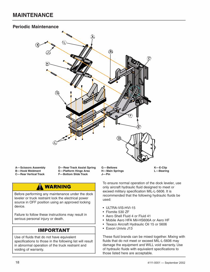
Periodic Maintenance
To ensure normal operation of the dock leveler, useonly aircraft hydraulic fluid designed to meet orexceed military specification MIL-L-5606. It isrecommended that the following hydraulic fluids beused:
• ULTRA-VIS-HVI-15• Flomite 530 ZF• Aero Shell Fluid 4 or Fluid 41• Mobile Aero HFA Mil-HS606A or Aero HF• Texaco Aircraft Hydraulic Oil 15 or 5606• Exxon Univis J13
These fluid brands can be mixed together. Mixing withfluids that do not meet or exceed MIL-L-5606 maydamage the equipment and WILL void warranty. Useof hydraulic fluids with equivalent specifications tothose listed here are acceptable.
A— Scissors AssemblyB— Hook WeldmentC— Rear Vertical Track
D— Rear Track Assist SpringE— Platform Hinge AreaF— Bottom Slide Track
G — BellowsH— Main SpringsJ— Pin
K— E-ClipL —Bearing
IMPORTANT Use of fluids that do not have equivalentspecifications to those in the following list will resultin abnormal operation of the truck restraint andvoiding of warranty.
Before performing any maintenance under the dockleveler or truck restraint lock the electrical powersource in OFF position using an approved lockingdevice.
Failure to follow these instructions may result inserious personal injury or death.
A
B
C
E
D
K
F
L
H
L
G
J
194111-0015 — November 2009
MAINTENANCE
Daily Maintenance
• Daily patrol truck restraint area and clear anydebris to prevent operation issues.
• Check inside and outside lights for properoperation
Weekly Maintenance
• Operate the truck restraint through the completeoperating cycle to maintain lubrication of parts ofboth mechanical and hydraulic restraints.
• Inspect the rear vertical track area (C). The trackarea must be kept free of dirt and debris. Build-upof foreign material in the track areas will causeabnormal operation.
Clear all dirt and debris from the track areas toinsure proper scissor operation and hook weldmenttravel.
NOTE: To thoroughly inspect and clean the scissorsand track areas raise the restraint, removetwo bolts (L), pull shroud & bellows forward toexpose scissors and frame tracks,
Make sure Rear Track Assist Spring (D) is properlyseated at the bottom of the rear track.
NOTE: Rear Track Assist Spring is different partnumber for mechanical and hydraulicPowerStop truck restraint
• Lubricate the following areas with light weightmachine oil:
(A)— Scissor pins and bearings (J&L-all)
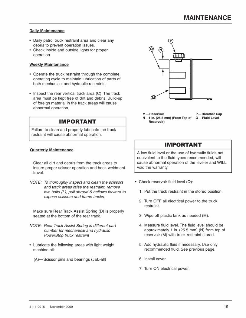
M — ReservoirN —1 in. (25.5 mm) (From Top of
Reservoir)
P — Breather CapQ — Fluid Level
• Check reservoir fluid level (Q):
1. Put the truck restraint in the stored position.
2. Turn OFF all electrical power to the truck restraint.
3. Wipe off plastic tank as needed (M).
4. Measure fluid level. The fluid level should beapproximately 1 in. (25.5 mm) (N) from top ofreservoir (M) with truck restraint stored.
5. Add hydraulic fluid if necessary. Use onlyrecommended fluid. See previous page.
6. Install cover.
7. Turn ON electrical power.
IMPORTANTFailure to clean and properly lubricate the truckrestraint will cause abnormal operation.
IMPORTANTA low fluid level or the use of hydraulic fluids notequivalent to the fluid types recommended, willcause abnormal operation of the leveler and WILLvoid the warranty.
M
NQ
P
Quarterly Maintenance

20 4111-0015 — November 2009
PARTS
STOP-TITE® M (Mechanical) Parts Breakdown
2

214111-0015 — November 2009
PARTS
STOP-TITE® M (Mechanical) Parts Breakdown
Item Quantity Part Number Description
1 1 0191-0025 Bellows W/ 1 X 13=1/2 Velcro Strips2 1 0941-0015 Spring, 1-7/8 DIA X 6.003 1 0615-0037 Stored Limit Switch with Bracket, NC4 1 1751-0649 Decal-Systems, Inc./STOP-TITER, 3-3/4 X 14-1./2
5 1 1751-0010 Decal-Serial Number
6 1 1751-0135 Decal-Warning7 2 2101-0009 HHCS-Grade 2-Zinc Plated, 5-16-18 UNC X 3/48 8 2101-0084 HHCS-Grade 5-Zinc Plated , 1/4-20 UNC X 3/49 1 2101-0085 Washer-Flat-Zinc Plated, 1-1/8 DIA10 8 2101-0143 Nylon Lock Nut, 1/4-20 UNC11 2 2101-0150 RHMS-Slotted, 10-24 UNC X 2-1/412 2 2101-0151 Nylon Lock Nut, #10-24 UNC13 1 2101-0165 Shoulder Bolt,1/2 DIA X 5/814 8 2101-0189 E-Clip, 1/215 2 2101-0212 Flat Head Cap Screw, 1/2-13 UNC X 117 1 5455-0005 Level Weldment-Release18 2 9202-0042 Pin-Pivot-Long, 1/2 DIA19 2 9202-0043 Pin-Pivot-Short, 1/2 DIA20 1 9411-0045 Shroud-Bellows Mounting-STOP-TITE®
21 2 9412-0161 Tube, 1-1/4 OD X 9-16 ID X 5/822 1 9412-0201 Bar-Bellows Mounting-Front23 2 9412-0202 Bar-Bellows Mounting-Side 24 2 9412-0215 Bar-Bellows Mounting
25A 1 9413-0049 Restraint Weldment-STOP-TITE®-Standard Profile-2 Stage25B 1 9413-0055 Restraint Weldment-STOP-TITE®-Low Profile-2 Stage26 1 9413-0062 Scissor Lift Sub-Assembly-STOP-TITE®
27 1 9413-0068 Spacer Assembly-STOP-TITE® Mechanical28 1 9413-0070 Release Lever Assembly-STOP-TITE® Mechanical29 1 9413-0100 Deflector, Lip-27”-STOP-TITE®
30 1 9414-0062 Final Base Weldment-27”-STOP-TITE®
16 1 2103-0006 Driveway Mount - Optional

22 4111-0015 — November 2009
PARTS
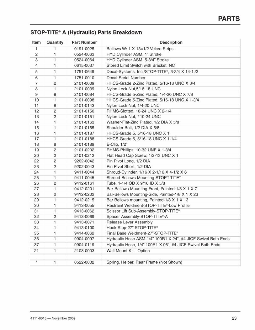
STOP-TITE® A (Hydraulic) Parts Breakdown
234111-0015 — November 2009
PARTS
Item Quantity Part Number Description
1 1 0191-0025 Bellows W/ 1 X 13=1/2 Velcro Strips2 1 0524-0063 HYD Cylinder ASM, 1” Stroke3 1 0524-0064 HYD Cylinder ASM, 5-3/4” Stroke4 1 0615-0037 Stored Limit Switch with Bracket, NC
5 1 1751-0649 Decal-Systems, Inc./STOP-TITE®, 3-3/4 X 14-1./2
6 1 1751-0010 Decal-Serial Number7 2 2101-0009 HHCS-Grade 2-Zinc Plated, 5/16-18 UNC X 3/48 1 2101-0039 Nylon Lock Nut,5/16-18 UNC9 8 2101-0084 HHCS-Grade 5-Zinc Plated, 1/4-20 UNC X 7/810 1 2101-0098 HHCS-Grade 5-Zinc Plated, 5/16-18 UNC X 1-3/411 8 2101-0143 Nylon Lock Nut, 1/4-20 UNC12 2 2101-0150 RHMS-Slotted, 10-24 UNC X 2-1/413 2 2101-0151 Nylon Lock Nut, #10-24 UNC14 1 2101-0163 Washer-Flat-Zinc Plated, 1/2 DIA X 5/815 1 2101-0165 Shoulder Bolt, 1/2 DIA X 5/816 1 2101-0187 HHCS-Grade 5, 5/16-18 UNC X 117 1 2101-0188 HHCS-Grade 5, 5/16-18 UNC X 1-1/418 8 2101-0189 E-Clip, 1/2”19 2 2101-0202 RHMS-Phillips, 10-32 UNF X 1-3/420 2 2101-0212 Flat Head Cap Screw, 1/2-13 UNC X 122 2 9202-0042 Pin Pivot Long, 1/2 DIA23 2 9202-0043 Pin Pivot Short, 1/2 DIA24 1 9411-0044 Shroud-Cylinder, 1/16 X 2-1/16 X 4-1/2 X 625 1 9411-0045 Shroud-Bellows Mounting-STOPT-TITE™
26 2 9412-0161 Tube, 1-1/4 OD X 9/16 ID X 5/827 1 9412-0201 Bar-Bellows Mounting-Front, Painted-1/8 X 1 X 728 2 9412-0202 Bar-Bellows Mounting-Side, Painted-1/8 X 1 X 2329 1 9412-0215 Bar Bellows mounting, Painted-1/8 X 1 X 1330 1 9413-0055 Restraint Weldment-STOP-TITE®-Low Profile31 1 9413-0062 Scissor Lift Sub-Assembly-STOP-TITE®
32 2 9413-0069 Spacer Assembly-STOP-TITE®-A33 1 9413-0071 Release Lever Assembly34 1 9413-0100 Hook Stop-27” STOP-TITE®
35 1 9414-0062 Final Base Weldment-27”-STOP-TITE®
36 1 9904-0097 Hydraulic Hose ASM-1/4” 100R1 X 24”, #4 JICF Swivel Both Ends37 1 9904-0119 Hydraulic Hose, 1/4” 100R1 X 96”, #4 JICF Swivel Both Ends21 1 2103-0003 Wall Mount Kit - Option
* 1 0522-0002 Spring, Helper, Rear Frame (Not Shown)
STOP-TITE® A (Hydraulic) Parts Breakdown

24 4111-0015 — November 2009
PARTS
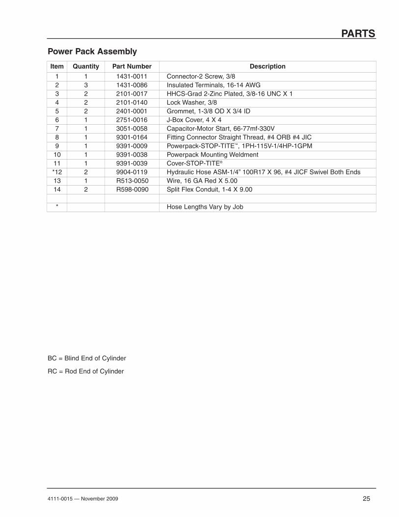
Power Pack Assembly
AMP Drawing 4.8-5.2
254111-0015 — November 2009
PARTS
Power Pack Assembly
Item Quantity Part Number Description
1 1 1431-0011 Connector-2 Screw, 3/82 3 1431-0086 Insulated Terminals, 16-14 AWG3 2 2101-0017 HHCS-Grad 2-Zinc Plated, 3/8-16 UNC X 14 2 2101-0140 Lock Washer, 3/85 2 2401-0001 Grommet, 1-3/8 OD X 3/4 ID6 1 2751-0016 J-Box Cover, 4 X 47 1 3051-0058 Capacitor-Motor Start, 66-77mf-330V8 1 9301-0164 Fitting Connector Straight Thread, #4 ORB #4 JIC9 1 9391-0009 Powerpack-STOP-TITE™, 1PH-115V-1/4HP-1GPM10 1 9391-0038 Powerpack Mounting Weldment11 1 9391-0039 Cover-STOP-TITE®
*12 2 9904-0119 Hydraulic Hose ASM-1/4” 100R17 X 96, #4 JICF Swivel Both Ends13 1 R513-0050 Wire, 16 GA Red X 5.0014 2 R598-0090 Split Flex Conduit, 1-4 X 9.00
* Hose Lengths Vary by Job
BC = Blind End of Cylinder
RC = Rod End of Cylinder
26 4111-0015 — November 2009
PARTS
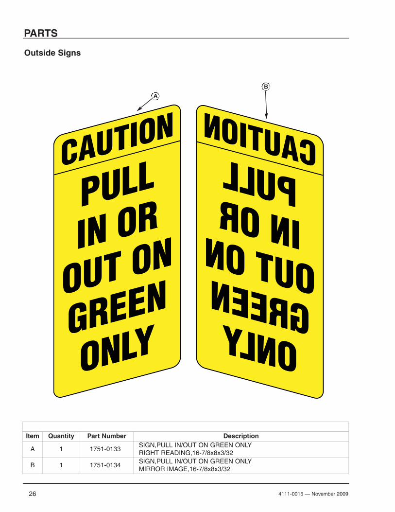
Outside Signs
CAUTION
PULLIN OR
OUT ON
GREEN
ONLY
CAUTION
PULLIN OR
OUT ON
GREEN
ONLY
Item Quantity Part Number Description
A 1 1751-0133SIGN,PULL IN/OUT ON GREEN ONLYRIGHT READING,16-7/8x8x3/32
B 1 1751-0134SIGN,PULL IN/OUT ON GREEN ONLYMIRROR IMAGE,16-7/8x8x3/32
B
A

274111-0015 — November 2009
PARTS
OSLA (Outside Light Assembly)
Item Quantity Part Number Description1-7 1 3055-0008 Complete Light Housing, Yellow Plastic, LED Lights1-7 1 3055-0002 Complete Light Housing, Yellow Plastic, Incandescent Lights1 1 3051-0002 Light Housing Only, Yellow Plastic2 1 3051-0064 Lens Red, for use with incandescent bulbs3 1 3051-0065 Lens Green, for use with incandescent bulbs* 2 3051-0085 Lamp, 25W,120V,Incandescent, BAY (Rated 1000 Hours)* 2 3051-0066 Socket Harness for Incandescent Lamp2 1 3051-0102 Lens/Housing/Circuit Assembly Red-LED3 1 3051-0103 Lens/Housing/Circuit Assembly Green-LED4 1 3051-0068 Mounting Gasket5 4 3051-0105 Clips, Lens Holding6 4 3051-0104 Screw, Lens Holding Clip7 1 x Conduit Fastener, 3/4” x 3/8”

28 4111-0015 — November 2009
NOTES
This Page Intentionally Left Blank

294111-0015 — November 2009
MISCELLANEOUS
Customer Information
NOTE: Refer to illustration for left/right orientation ofDock Leveler and Truck Restraint.
The model/serial number decal (A) is locatedon the right platform joist near the front (lip)of dock leveler. The Truck Restraint serialnumber is located on the left side of thebellows shroud.
When you receive your STOP-TITE® Truck Restraint,write down the Truck Restraint and Dock Levelerserial number (if applicable) in the form provided. Thiswill help ensure safe keeping of the numbers in theevent the model/serial number decal (A) becomeslost or damaged.
Also, write down McGuire’s job number (found insidethe control box door on a white sticker), the companythat installed the dock leveler, and the originalowner’s name. This will all help to identify the specificdock leveler if more information is required.
When ordering, use part numbers and description tohelp identify the item ordered. Do not use “item”numbers. These are only for locating the position ofthe parts. Always give truck restraint MODELNUMBER and/or SERIAL NUMBER.
For service, call or contact:
McGuireP.O. Box 309Germantown, WI 53022Phone: (800) 624-8473Fax: (262) 255-5917
Truck Restraint Information
Model ___________________________________
Serial No. ________________________________
McGuire’s, Job No. ______________________
Dock Leveler Information
Model ___________________________________
Serial No. ________________________________
McGuire’s Job No. ______________________
Original Owner Information
Name ___________________________________
Address _________________________________
________________________________
Installer Information
Name ___________________________________
Address _________________________________
_________________________________
Date of Installation ________________________
A
PR052
McGuire WARRANTY
STOP-TITE® SERIES TRUCK RESTRAINT
McGuire, guarantees the materials, components, and workmanship in your McGuiretruck restraint to be of the highest quality and to be free of defects in material andworkmanship for a period of One (1) Year from date of shipment. Specifically thisincludes the frame and all mechanical components.
McGuire, further guarantees the hydraulic components (where equipped) on allMcGuire truck restraints for a period of One (1) Year from date of shipment.
Specifically this guarantee applies to:
• Fluid valves and valve body control assembly• All hydraulic cylinders• Hydraulic pressure lines• Hydraulic pump and motor.
The electrical components carry a One (1) year warranty.
In the event of any defect covered by this guarantee, McGuire will remedy saiddefect by repairing or replacing all defective parts, bearing all of the costs for parts,labor, and transportation.
All guarantee claims will be settled on a timely basis when defects are found to befrom other than improper installation, operating contrary to instructions or beyondrated load capacities, abuse, careless or negligent use, or failure to maintain theunit as recommended by the owner's manual.
There are no guarantees, either expressed or implied, including any impliedguarantees of merchantability or fitness for a particular purpose which shall extendbeyond the guarantee periods indicated above. This guarantee is valid only if theunit(s) is unaltered from original condition as delivered from the factory and asurvey is completed by a McGuire representative.