storagetek addendum 95845y1 code release 5.8 · addendum 95845y1 code release 5.8.0c l1400x tape...
TRANSCRIPT

StorageTekTM
Addendum 95845Y1Code Release 5.8.0cL1400x Tape Library and Pass-Thru Port
Operator’s GuidePart Number: Addendum_95845Y1
Revision: A

Sun Microsystems, Inc.www.sun.com
Submit comments about this document at: http://www.sun.com/hwdocs/feedback
StorageTek™
Addendum 95845Y1Code Release 5.8.0cL1400x Tape Libraryand Pass-Thru Port
Operator’s Guide
Part No. Addendum 95845Y1October 2006, Revision A
PleaseRecycle
Revision A • 95845Y1
Copyright 2005 Sun Microsystems, Inc., 4150 Network Circle, Santa Clara, California 95054, U.S.A. All rights reserved.
Sun Microsystems, Inc. has intellectual property rights relating to technology that is described in this document. In particular, and without limitation, these intellectual property rights may include one or more of the U.S. patents listed at http://www.sun.com/patents and one or more additional patents or pending patent applications in the U.S. and in other countries.
This document and the product to which it pertains are distributed under licenses restricting their use, copying, distribution, and decompilation. No part of the product or of this document may be reproduced in any form by any means without prior written authorization of Sun and its licensors, if any.
Third-party software, including font technology, is copyrighted and licensed from Sun suppliers.
Parts of the product may be derived from Berkeley BSD systems, licensed from the University of California. UNIX is a registered trademark in the U.S. and in other countries, exclusively licensed through X/Open Company, Ltd.
Sun, Sun Microsystems, the Sun logo, Java, AnswerBook2, docs.sun.com, Solaris, and StorageTek are trademarks or registered trademarks of Sun Microsystems, Inc. in the U.S. and in other countries.
All SPARC trademarks are used under license and are trademarks or registered trademarks of SPARC International, Inc. in the U.S. and in other countries. Products bearing SPARC trademarks are based upon an architecture developed by Sun Microsystems, Inc.
The OPEN LOOK and Sun™ Graphical User Interface was developed by Sun Microsystems, Inc. for its users and licensees. Sun acknowledges the pioneering efforts of Xerox in researching and developing the concept of visual or graphical user interfaces for the computer industry. Sun holds a non-exclusive license from Xerox to the Xerox Graphical User Interface, which license also covers Sun’s licensees who implement OPEN LOOK GUIs and otherwise comply with Sun’s written license agreements.
U.S. Government Rights—Commercial use. Government users are subject to the Sun Microsystems, Inc. standard license agreement and applicable provisions of the FAR and its supplements.
DOCUMENTATION IS PROVIDED "AS IS" AND ALL EXPRESS OR IMPLIED CONDITIONS, REPRESENTATIONS AND WARRANTIES, INCLUDING ANY IMPLIED WARRANTY OF MERCHANTABILITY, FITNESS FOR A PARTICULAR PURPOSE OR NON-INFRINGEMENT, ARE DISCLAIMED, EXCEPT TO THE EXTENT THAT SUCH DISCLAIMERS ARE HELD TO BE LEGALLY INVALID.
Copyright 2005 Sun Microsystems, Inc., 4150 Network Circle, Santa Clara, Californie 95054, Etats-Unis. Tous droits réservés.
Sun Microsystems, Inc. a les droits de propriété intellectuels relatants à la technologie qui est décrit dans ce document. En particulier, et sans la limitation, ces droits de propriété intellectuels peuvent inclure un ou plus des brevets américains énumérés à http://www.sun.com/patents et un ou les brevets plus supplémentaires ou les applications de brevet en attente dans les Etats-Unis et dans les autres pays.
Ce produit ou document est protégé par un copyright et distribué avec des licences qui en restreignent l’utilisation, la copie, la distribution, et la décompilation. Aucune partie de ce produit ou document ne peut être reproduite sous aucune forme, par quelque moyen que ce soit, sans l’autorisation préalable et écrite de Sun et de ses bailleurs de licence, s’il y en a.
Le logiciel détenu par des tiers, et qui comprend la technologie relative aux polices de caractères, est protégé par un copyright et licencié par des fournisseurs de Sun.
Des parties de ce produit pourront être dérivées des systèmes Berkeley BSD licenciés par l’Université de Californie. UNIX est une marque déposée aux Etats-Unis et dans d’autres pays et licenciée exclusivement par X/Open Company, Ltd.
Sun, Sun Microsystems, le logo Sun, Java, AnswerBook2, docs.sun.com, Solaris, et StorageTek sont des marques de fabrique ou des marques déposées de Sun Microsystems, Inc. aux Etats-Unis et dans d’autres pays.
Toutes les marques SPARC sont utilisées sous licence et sont des marques de fabrique ou des marques déposées de SPARC International, Inc. aux Etats-Unis et dans d’autres pays. Les produits portant les marques SPARC sont basés sur une architecture développée par Sun Microsystems, Inc.
L’interface d’utilisation graphique OPEN LOOK et Sun™ a été développée par Sun Microsystems, Inc. pour ses utilisateurs et licenciés. Sun reconnaît les efforts de pionniers de Xerox pour la recherche et le développement du concept des interfaces d’utilisation visuelle ou graphique pour l’industrie de l’informatique. Sun détient une license non exclusive de Xerox sur l’interface d’utilisation graphique Xerox, cette licence couvrant également les licenciées de Sun qui mettent en place l’interface d ’utilisation graphique OPEN LOOK et qui en outre se conforment aux licences écrites de Sun.
LA DOCUMENTATION EST FOURNIE "EN L’ÉTAT" ET TOUTES AUTRES CONDITIONS, DECLARATIONS ET GARANTIES EXPRESSES OU TACITES SONT FORMELLEMENT EXCLUES, DANS LA MESURE AUTORISEE PAR LA LOI APPLICABLE, Y COMPRIS NOTAMMENT TOUTE GARANTIE IMPLICITE RELATIVE A LA QUALITE MARCHANDE, A L’APTITUDE A UNE UTILISATION PARTICULIERE OU A L’ABSENCE DE CONTREFAÇON.
We welcome your feedback. Please contact the Global Learning Solutions Feedback System at:
or
Global Learning SolutionsSun Microsystems, Inc.One StorageTek DriveLouisville, CO 80028-3256USA
Please include the publication name, part number, and edition number in your correspondence if they are available. This will expedite our response.

Revision History
Date Revision Description
October 2006 A Initial Release
95845Y1 • Revision A 3

4 Addendum 95845Y1 • October 2006 Revision A • 95845Y1

95845Y1 • Revision A 5
Contents
1. L1400 Product Update 27
Basics 27
Additional L1400 Library Conversions Available 28
L1400 Library Overview 28
Partitioning 31
Ordering a Partitioning Access Key 33
Installing a Partitoning Access Key 35
Assigning Library Resources to Partitions 35
Assigning Cartridge Slots to a Partition 37
Assigning Drives to a Partition 40
Assigning CAPs to a Partition 41
Assigning Hosts/Backup Applications to Partitions 43
Changing the Default Maps 45
Editing the Default Partition Maps 45
Partitioned Element Address Presentation 46
Address Translation Table 48
Continuous Capacity 51
Ordering a Capacity Access Key 51
Installing a Capacity Access Key 54
Allocating Capacity 55
Continuous Capacity Cartridge Slot Presentation 57
Address Translation Table 58
Moving Media, Single Library 63
Moving Media with the Pass-Thru Port 65

6 Addendum 95845Y1 • October 2006 Revision A • 95845Y1
95845Y1 • Revision A Figures 7
Figures
FIGURE 1-1 L1400M Key Order Form 34
FIGURE 1-2 L1400 ICM Main Menu. 35
FIGURE 1-3 L1400 ICM Summary Page. 36
FIGURE 1-4 Partition Information Screen 37
FIGURE 1-5 Edit Slots Page 38
FIGURE 1-6 Save Changes Page 39
FIGURE 1-7 Edit Drives Page. 41
FIGURE 1-8 Edit Cartridge Access Port Page 42
FIGURE 1-9 Mapping Page 43
FIGURE 1-10 Host Port Information Window 44
FIGURE 1-11 Edit/View Map Window 46
FIGURE 1-12 Capacity Management Information Page. 48
FIGURE 1-13 Address Translation Window 50
FIGURE 1-14 L1400 Key Order Form. 53
FIGURE 1-15 L1400 ICM Main Menu 54
FIGURE 1-16 Capacity Management Page. 55
FIGURE 1-17 Edit Capacity Management Page. 56
FIGURE 1-18 “Save Changes” Page. 56
FIGURE 1-19 Capacity Management Information Page. 59
FIGURE 1-20 Address Translation Window, Slots Tab 60
FIGURE 1-21 .Address Translation Window, Drives Tab. 61
FIGURE 1-22 Address Translation Window, CAPs Tab. 62
FIGURE 1-23 Address Translation Window, PTP Tabs. 63
FIGURE 1-24 Move Media Window. 64
FIGURE 1-25 Confirmation Window. 64

8 Addendum 95845Y1 • October 2006 Revision A • 95845Y1

95845Y1 • Revision A Tables 9
Tables
TABLE 1-1 Additional Available L1400 Library Configurations and Conversions 28
TABLE 1-2 Key Order Form Fields 33
TABLE 1-3 Example: Physical Address / Logical Partition Address 47
TABLE 1-4 Address Translation Window Information Tabs 49
TABLE 1-5 Key Order Form Fields 52
TABLE 1-6 Physical Address / Logical Partition Address 57
TABLE 1-7 Address Translation Window, Slots Tabs 60
TABLE 1-8 Address Translation Window, Drive Tabs 61
TABLE 1-9 Address Translation Window, CAPs Tabs 62
TABLE 1-10 Address Translation Window, PTP Tabs 63

10 Addendum 95845Y1 • October 2006 Revision A • 95845Y1
Preface
This book is an addendum to the L700x/L1400x Tape Libraries and Pass-Thru Port Operator’s Guide, Part Number 95845, and is intended to supplement the information in that document.
This document provides information for L1400M1 control interface code level 5.8.0c, and has illustrations of user interface pages specifically for this code level. Screens from earlier code levels may appear similar, and much of the information provided here applies to those earlier code releases.
This guide is intended primarily for data center operators. System programmers and computer system administrators might also find the information useful.
Organization of This PublicationThis table provides a general overview of the chapters in this publication.
Alert MessagesAlert messages call your attention to information that is especially important or that has a unique relationship to the main text or graphic.
Note – A note provides additional information that is of special interest. A note might point out exceptions to rules or procedures. A note usually, but not always, follows the information to which it pertains.
Chapter 1 “L1400 Product Update” Provides an overview of the available L1400M, L1400P, and L1400MA products, including a list of the most-recent available upgrades and conversions.Provides theory and procedural information about partitioning, and about the Continuous Capacity feature in the L1400 library family
95845Y1 • Revision A 11
Caution – A caution informs you of conditions that might result in damage to hardware, corruption of data, or corruption of application software. A caution always precedes the information to which it pertains.
Warning – Possible Physical Injury. A warning alerts you to conditions that might result in long-term health problems, injury, or death. A warning always precedes the information to which it pertains.
Mensajes de alertaLos mensajes de alerta llaman la atención hacia información de especial importancia o que tiene una relación específica con el texto principal o los gráficos.
Nota – Una nota expone información adicional que es de interés especial. Una nota puede señalar excepciones a las normas o procedimientos. Por lo general, aunque no siempre, las notas van después de la información a la que hacen referencia.
Precaución – Una precaución informa sobre situaciones que podrían conllevar daños del hardware, de los datos o del software de aplicación. Las precauciones van siempre antes de la información a la que hacen referencia.
Advertencia – Posibles lesiones. Una advertencia llama la atención sobre condiciones que podrían conllevar problemas de salud crónicos, lesiones o muerte. Las advertencias van siempre antes de la información a la que hacen referencia.
12 Addendum 95845Y1 • October 2006 Revision A • 95845Y1

Typographic Conventions
Third-Party Web SitesSun is not responsible for the availability of third-party web sites mentioned in this document. Sun does not endorse and is not responsible or liable for any content, advertising, products, or other materials that are available on or through such sites or resources. Sun will not be responsible or liable for any actual or alleged damage or loss caused by or in connection with the use of or reliance on any such content, goods, or services that are available on or through such sites or resources.
Sun Welcomes Your CommentsSun is interested in improving its documentation and welcomes your comments and suggestions. You can submit your comments by going to:http://www.sun.com/hwdocs/feedback
Please include the title and part number of your document with your feedback:
Addendum 95845Y1, part number 95845Y1
Typeface*
* The settings on your browser might differ from these settings.
Meaning Examples
AaBbCc123 The names of commands, files, and directories; on-screen computer output
Edit your.login file.Use ls -a to list all files.% You have mail.
AaBbCc123 What you type, when contrasted with on-screen computer output
% suPassword:
AaBbCc123 Book titles, new words or terms, words to be emphasized. Replace command-line variables with real names or values.
Read Chapter 6 in the User’s Guide.These are called class options.You must be superuser to do this.To delete a file, type rm filename.
95845Y1 • Revision A Preface 13

14 Addendum 95845Y1 • October 2006 Revision A • 95845Y1

Notices
Please read the following compliance and warning statements for this product.
Caution – Potential equipment damage: Cables that connect peripherals must be shielded and grounded; refer to descriptions in the cable instruction manuals. Operation of this equipment with cables that are not shielded and not correctly grounded might result in interference to radio and TV reception.
Changes or modifications to this equipment that are not expressly approved in advance by StorageTek will void the warranty. In addition, changes or modifications to this equipment might cause it to create harmful interference.
United States FCC Compliance StatementThe following compliance statement pertains to Federal Communications Commission Rules 47 CFR 15.105:
Note – This equipment has been tested and found to comply with the limits for a Class A digital device pursuant to part 15 of the FCC Rules. These limits are designed to provide reasonable protection against harmful interference when the equipment is operated in a commercial environment. This equipment generates, uses, and can radiate radio frequency energy and, if not installed and used in accordance with the instruction manual, may cause harmful interference to radio communications. Operation of this equipment in a residential area is likely to cause harmful interference in which case the user will be required to correct the interference at his or her own expense.
CISPR 22 and EN55022 WarningThis is a Class A product. In a domestic environment this product may cause radio interference in which case the user may be required to take adequate measures.
95845Y1 • Revision A 15

Japanese Compliance StatementThe following compliance statement in Japanese pertains to VCCI EMI regulations:
English translation: This is a Class A product based on the Technical Requirement of the Voluntary Control Council for Interference by Information Technology (VCCI). In a domestic environment, this product may cause radio interference, in which case the user may be required to take corrective actions.
Taiwan Warning Label Statement
The following warning label statement pertains to BSMI regulations in Taiwan, R.O.C.:
English translation: This is a Class A product. In a domestic environment, this product may cause radio interference, in which case, the user may be required to take adequate measures.
Internal Code License StatementThe following is the Internal Code License Agreement from StorageTek:
16 Addendum 95845Y1 • October 2006 Revision A • 95845Y1

The following is the Internal Code License Agreement from StorageTek:NOTICE
INTERNAL CODE LICENSEPLEASE READ THIS NOTICE CAREFULLY BEFORE INSTALLING AND OPERATING THIS EQUIPMENT. THIS NOTICE IS A LEGAL AGREEMENT BETWEEN YOU (EITHER AN INDIVIDUAL OR ENTITY), THE END USER, AND STORAGE TECHNOLOGY CORPORATION (“STORAGETEK”), THE MANUFACTURER OF THE EQUIPMENT. BY OPENING THE PACKAGE AND ACCEPTING AND USING ANY UNIT OF EQUIPMENT DESCRIBED IN THIS DOCUMENT, YOU AGREE TO BECOME BOUND BY THE TERMS OF THIS AGREEMENT. IF YOU DO NOT AGREE WITH THE TERMS OF THIS AGREEMENT, DO NOT OPEN THE PACKAGE AND USE THE EQUIPMENT. IF YOU DO NOT HAVE THE AUTHORITY TO BIND YOUR COMPANY, DO NOT OPEN THE PACKAGE AND USE THE EQUIPMENT. IF YOU HAVE ANY QUESTIONS, CONTACT THE AUTHORIZED STORAGETEK DISTRIBUTOR OR RESELLER FROM WHOM YOU ACQUIRED THIS EQUIPMENT. IF THE EQUIPMENT WAS OBTAINED BY YOU DIRECTLY FROM STORAGETEK, CONTACT YOUR STORAGETEK REPRESENTATIVE.
1. Definitions: The following terms are defined as follows:a. “Derivative works” are defined as works based
upon one or more preexisting works, such as a translation or a musical arrangement, or any other form in which a work may be recast, transformed, or adapted. A work consisting of editorial revision, annotations, elaboration, or other modifications which, as a whole, represent an original work of authorship, is a Derivative work.
b. “Internal Code” is Microcode that (i) is an integral part of Equipment, (ii) is required by such Equipment to perform its data storage and retrieval functions, and (iii) executes below the user interface of such Equipment. Internal code does not include other Microcode or software, including data files, which may reside or execute in or be used by or in connection with such Equipment, including, without limitation, Maintenance Code.
c. “Maintenance Code” is defined as Microcode and other software, including data files, which may reside or execute in or be used by or in connection with Equipment, and which detects, records, displays, and/or analyzes malfunctions in the Equipment.
d. “Microcode” is defined as a set of instructions (software) that is either imbedded into or is to be loaded into the Equipment and executes below the external user interface of such Equipment. Microcode includes both Internal Code and Maintenance Code, and may be in magnetic or other storage media, integrated circuitry, or other media.
2. The Equipment you have acquired by purchase or lease is manufactured by or for StorageTek and contains Microcode. By accepting and operating this Equipment, you acknowledge that StorageTek or its licensor(s) retain(s) ownership of all Microcode, as well as all copies thereof, that may execute in or be used in the operation or servicing of the Equipment and that such Microcode is copyrighted by StorageTek or its licensor(s).
3. StorageTek hereby grants you, the end user of the Equipment, a personal, nontransferable (except as permitted in the transfer terms below), nonexclusive license to use each copy of the Internal Code (or any replacement provided by StorageTek or your authorized StorageTek distributor or reseller) which license authorizes you, the end user, to execute the Internal Code solely to enable the specific unit of Equipment for which the copy of Internal Code is provided to perform its data storage and retrieval functions in accordance with StorageTek’s (or its licensor’s) official published specifications.
4. Your license is limited to the use of the Internal Code as set forth. You may not use the Internal Code for any other purpose. You may not, for example, do any of the following:
(i) access, copy, display, print, adapt, alter, modify, patch, prepare Derivative works of, transfer, or distribute (electronically or otherwise) or otherwise use the Internal Code;(ii) reverse assemble, decode, translate, decompile, or otherwise reverse engineer the Internal Code (except as decompilation may be expressly permitted under applicable European law solely for the purpose of gaining information that will allow interoperability when such information is not otherwise readily available); or(iii) sublicense, assign, or lease the Internal Code or permit another person to use such Internal Code, or any copy of it.
95845Y1 • Revision A Notices 17

5. Nothing in the license set forth above or in this entire Notice shall convey, in any manner, to you any license to or title to or other right to use any Maintenance code, or any copy of such Maintenance Code. Maintenance Code and StorageTek’s service tools and manuals may be kept at your premises, or they may be supplied with a unit of Equipment sent to you and/or included on the same media as Internal Code, but they are to be used only by StorageTek’s customer service personnel or those of an entity licensed by StorageTek, all rights in and to such Maintenance Code, service tools and manuals being reserved by StorageTek or its licensors. You agree that you shall not use or attempt to use the Maintenance Code or permit any other third party to use and access such Maintenance Code.
6. You, the end user, agree to take all appropriate steps to ensure that all of your obligations set forth in this Notice are extended to any third party having access to the Equipment.
7. You may transfer possession of the Internal Code to another party only with the transfer of the Equipment on which its use is authorized, and your license to use the Internal Code is discontinued when you are no longer an owner or a rightful possessor of the Equipment. You must give such transferee all copies of the Internal Code for the transferred Equipment that are in your possession, along with a copy of all provisions of this Notice.
Any such transfer by you is automatically (without further action on the part of either party) expressly subject to all the terms and conditions of this Notice passing in full to the party to whom such Equipment is transferred, and such transferee accepts the provisions of this license by initial use of the Internal Code. You cannot pass to the transferee of the Equipment any greater rights than granted under this Notice, and shall hold StorageTek harmless from any claim to the contrary by your transferee or its successors or assigns. In addition, the terms and conditions of this Notice apply to any copies of Internal Code now in your possession or use or which you hereafter acquire from either StorageTek or another party.
8. You acknowledge that copies of both Internal Code and Maintenance Code may be installed on the Equipment before shipment or included with the Equipment and other material shipped to you, all for the convenience of StorageTek’s service personnel or service providers licensed by StorageTek, and that during the warranty period, if any, associated with the Equipment, and during periods in which the Equipment is covered under a maintenance contract with StorageTek or service providers licensed by StorageTek, both Internal Code and Maintenance Code may reside and be executed in or used in connection with such Equipment, and you agree that no rights to Maintenance Code are conferred upon you by such facts.
StorageTek or the licensed service provider may keep Maintenance Code and service tools and manuals on your premises but they are to be used only by StorageTek’s customer service personnel or those of service providers licensed by StorageTek. You further agree that upon (i) any termination of such warranty period or maintenance contract period; or (ii) transfer of possession of the Equipment to another party, StorageTek and its authorized service providers shall have the right with respect to the affected Equipment to remove all service tools and manuals and to remove or disable all Maintenance Code and/or replace Microcode which includes both Internal Code and Maintenance Code with Microcode that consists only of Internal Code.
18 Addendum 95845Y1 • October 2006 Revision A • 95845Y1

Personal Safety
EN60950-1:2001 StatementThe following statement pertains to products that require a ground connection at the wall outlet.
Safety Precautions
Warning – Possible Physical Injury. On-the-job safety is important; therefore, observe the following safety precautions while you engage in any maintenance activity. Failing to follow these precautions could result in serious injury.
■ Remove all conductive jewelry, such as watches and rings, before you service powered-on equipment.
■ Avoid electrical shock. Be careful when you work near power connectors and supplies.
■ Power-off the equipment that is being serviced before you remove a field replaceable unit (FRU) or other component. Remember that dangerous voltages could still be present in some areas even though power is off.
■ Ground all test equipment and power tools.
■ Be aware that the product hardware might have sharp edges that could injure you. Handle the equipment carefully and wear the appropriate gloves.
Norway:Apparatet må tilkoples jordet stikkontaktFinland:Laite on liitettävä suojamaadoituskoskettimilla varustettuun pistorasiaanSweden:Apparaten skall anslutas till jordat uttagDenmark:For tilslutning af de øvrige ledere, se medfølgende installationsvejledning.
95845Y1 • Revision A 19

■ Lift objects properly; read the information in “Lifting Techniques”.
■ Do not remove, cut, or relocate any floor tiles indiscriminately. Before you manipulate floor tiles, be sure that you understand the customer’s environment and receive the customer’s approval. Remember, each situation is different.
■ Enforce good housekeeping practices in the equipment area to help prevent fires and accidents.
Note – Important things to investigate and to be aware of include the use of Halon® gas, under-the-floor smoke detectors, and cables to other equipment installed nearby.
Lifting TechniquesLifting, regardless of how much or how little, can create serious back stress. If you follow these guidelines, you can reduce the risk of back injury:
■ Do not twist your body to pick up something or to put it down. Twisting puts extreme pressure on your back, especially when you lift or carry objects. Instead of twisting, make the task two separate moves; first lift, and then use your feet to turn your body.
■ Plan the lift; first examine the object and then determine how it should be lifted and where it will be placed.
■ Choose the appropriate lifting technique. Examine the weight, size, location, frequency, and direction of the lift. Plan to avoid awkward postures, and determine if material-handling aids are needed.
■ Place your feet shoulder-width apart, and place one foot a little behind the other. Keep your back straight because even light loads can significantly increase pressure on your spine when you lean forward.
■ Whenever you can, grip the load with your whole hand, and use two hands.
■ Carry objects at elbow height and close to your body. The farther away you hold an object, the more force it puts on your lower back.
■ Lift with your legs instead of your back. Leg muscles are some of the strongest in the body. When you squat and lift with your legs, you can lift more weight safely.
■ Alternate lifting tasks with tasks that are less stressful to the same muscles. This technique ensures that your muscles have some recovery time.
Shoulder, Elbow, Wrist, and Hand SafetyFollow these guidelines to minimize the possibility of injury to your shoulders, elbows, wrists, and hands.
■ Work within your safety zone—the area between shoulder level and knuckle level of your lowered hands. You face less chance of injury when you work or lift in this area.
■ Keep your elbows bent to keep loads close to your body and to decrease the amount of force necessary to do the job. If you use this posture, you will put less weight and pressure on your shoulder.
■ Be sure to keep your wrists straight. Avoid bending, extending, or twisting your wrists for long periods of time.
20 Addendum 95845Y1 • October 2006 Revision A • 95845Y1

■ Do not use a pinch grip to lift large or heavy loads because the way you lift also can affect the tendons in your hand. When you grasp an object between your thumb and fingers, you put a lot of tension on hand and wrist tendons. Use both hands—use one for a while, and then use the other—to give them rest.
Precauciones de seguridad
Advertencia – Posibles lesiones. La seguridad laboral es importante. Por consiguiente, adopte las siguientes precauciones de seguridad al realizar cualquier tarea de mantenimiento. El incumplimiento de dichas precauciones puede conllevar graves lesiones.
■ Antes de realizar cualquier tarea en equipos eléctricos conectados, quítese las joyas y accesorios conductores de electricidad, como relojes y anillos.
■ Evite las descargas eléctricas. Tenga cuidado al trabajar en la proximidades de conectores y alimentaciones eléctricas.
■ Antes de extraer unidad sustituible in situ u otro componente, apague el equipo y desconéctelo de la red eléctrica. Recuerde que, incluso si están apagados, en algunas áreas pueden quedar tensiones peligrosas.
■ Ponga a tierra todos los equipos de prueba y herramientas eléctricas.
■ El producto puede tener bordes afilados, susceptibles de provocar lesiones. Manipule el equipo adoptando las precauciones adecuadas, y utilice guantes.
■ Para levantar objetos, consulte la información de “Técnicas de levantamiento de objetos” on page 21.
■ No quite, corte ni cambie de lugar indiscriminadamente las baldosas. Antes de manipular baldosas, asegúrese de conocer el entorno del cliente y de recibir su autorización. Recuerde que cada situación es diferente.
■ Establezca, y haga cumplir, métodos de orden y limpieza en el área de equipos para evitar incendios y accidentes.
Nota – Entre los factores importantes que deben tenerse en cuenta es la presencia de gas Halón®, detectores de humo subterráneos y cables conductores a otros equipos instalados en las proximidades.
Técnicas de levantamiento de objetosEl levantar equipos o componentes, independientemente de su peso o tamaño, puede provocar serias lesiones lumbares. Siguiendo estas directrices podrá reducir los riesgos de lesiones.
■ No incline el cuerpo para levantar o bajar algo. Esta posición supone una tensión extrema para la espalda, en especial al levantar o transportar objetos. En lugar de inclinarse, efectúe dos movimientos: primero levante el componente y, a continuación, utilice los pies para girar el cuerpo.
95845Y1 • Revision A Personal Safety 21

■ Estos movimientos deben planificarse. En primer lugar, examine el objeto y determine cómo va a levantarlo y dónde va a colocarlo.
■ Seleccione la técnica de levantamiento adecuada. Examine el peso y tamaño del objeto, su ubicación y frecuencia y dirección en que vaya a levantarlo. La planificación debe hacerse de tal modo que se eviten posturas incómodas. Determine si son necesarios accesorios para la manipulación de materiales.
■ Separe bien las piernas y coloque una ligeramente detrás de la otra. Mantenga la espalda recta, porque incluso pesos ligeros pueden incrementar significativamente la presión sobre la espina dorsal al inclinarse hacia adelante.
■ En la medida de lo posible, sostenga la carga con toda la mano, y utilice ambas manos.
■ Transporte los objetos a la altura del codo y próximos a su cuerpo. Cuanto más lejos tenga que transportar un objeto, más presión aplicará sobre la zona lumbar.
■ Levante el objeto haciendo fuerza con las piernas, y no con la espalda. Los músculos de las piernas se cuentan entre los más fuertes del cuerpo. Al acuclillarse y levantar un peso con las piernas, tendrá mayor tolerancia al peso.
■ Alterne estas tareas con otras menos pesadas para los mismos músculos. De este modo, los músculos dispondrán de un cierto tiempo de recuperación.
Seguridad de hombros, codos, muñecas y manosSiga estas instrucciones para reducir al mínimo las posibilidades de lesionarse los hombros, codos, muñecas y manos.
■ Trabaje dentro de su zona de seguridad, el área entre el nivel de los hombros y el nivel de los nudillos. Trabajando o levantando objetos dentro de esta área se expondrá a menos probabilidades de lesiones.
■ Mantenga los codos inclinados para mantener las cargas próximas a su cuerpo y reducir la fuerza necesaria para realizar la tarea. Con esta postura, aplicará menos peso y presión sobre los hombros.
■ Asegúrese de mantener las muñecas rectas. Evite doblarlas, extenderlas o torcerlas durante períodos de tiempo prolongados.
■ No levante cargas grandes o pesadas con el puño cerrado, porque el modo de levantarlas también afecta a los tendones de la mano. Al tomar un objeto entre el pulgar y los dedos se aplica mucha tensión a las manos y tendones de las muñecas. Utilice ambas manos alternativamente, para permitir que descansen.
Fiber-optic Safety
Warning – Possible Physical Injury. Eye hazard. Never look directly into a fiber-optic cable, a fiber-optic connector, or a laser transceiver module. Hazardous conditions might exist from laser power levels that are capable of causing injury to your eyes.
Be especially careful when you use optical instruments with this equipment. Such instruments might increase the likelihood of injury to your eyes.
22 Addendum 95845Y1 • October 2006 Revision A • 95845Y1

Radiation exposure: Use of controls or adjustment or performance of procedures other than those specified herein might result in hazardous radiation exposure.
The laser transceivers in fiber-optic equipment can pose dangers to personal safety. Ensure that anyone who works with this StorageTek equipment understands these dangers and follows safety procedures. Ensure that the optical ports of every laser transceiver module are terminated with an optical connector, a dust plug, or a cover.
Each fiber-optic interface in this StorageTek Fibre Channel equipment contains a laser transceiver that is a Class 1 Laser Product. Each laser transceiver has an output of less than 70 µW. StorageTek’s Class 1 Laser Products comply with EN60825-1:1994+A1+A2 and with sections 21 CFR 1040.10 and 1040.11 of the Food and Drug Administration (FDA) regulations.
The following translations are for users in Finland and Sweden who wish to identify laser safety and classification:
CLASS 1 LASERLUOKAN 1 LASERLAITEKLASSE 1 LASER APPARAT
Laser Product LabelIn accordance with safety regulations, a label on each StorageTek Fibre Channel product identifies the laser class of the product and the place and date of the manufacturer. The label appears on top of a Fibre Channel tape drive and near the Fibre Channel connectors on a Fibre Channel tape library. A copy of the label is shown here:
Seguridad de fibras ópticas
Advertencia – Posibles lesiones. Riesgo para la vista. Nunca mire directamente el interior de un cable de fibra óptica, un conector de fibra óptica o un módulo transceptor de láser. Los niveles de potencia del láser pueden conllevar situaciones de riesgo, susceptibles de lesionar la vista.
Tenga especial cuidado al utilizar instrumentos ópticos con estos equipos. Dichos instrumentos pueden incrementar las probabilidades de lesiones oculares.
Exposición a radiaciones: El uso de mandos, ajustes o procedimientos distintos de los aquí especificados puede conllevar un riesgo de exposición a radiaciones.
CLASS 1 LASER PRODUCTLASER KLASSE 1
APPAREIL A LASER DE CLASSE 1COMPLIES WITH 21 CFR 1040.10 AND 1040.11
95845Y1 • Revision A Personal Safety 23

Los transceptores de láser de los equipos de fibra óptica pueden suponer un peligro para la seguridad física. Asegúrese de que toda persona que trabaje con estos equipos de StorageTek entienda los peligros y siga los procedimientos de seguridad. Asegúrese de que todos los puertos ópticos de los módulos transceptores de láser estén terminados con un conector óptico, una cubierta o un tapón de protección contra el polvo.
Todas las interfaces de fibra óptica de estos equipos de canal de fibra de StorageTek contienen un transceptor de láser, categorizado como Producto láser de Clase 1. Todos los transceptores de láser tienen una potencia de salida inferior a 70 µW. Los productos láser Clase 1 de StorageTek cumplen lo dispuesto por la norma EN60825-1:1994+A1+A2, así como con las secciones 21 CFR 1040.10 y 1040.11 de la Food and Drug Administration (FDA) de EE.UU.
Las siguientes traducciones están dirigidas a usuarios de Finlandia y Suecia que deseen identificar la categoría y clasificación de seguridad de los dispositivos láser:
LÁSER DE CLASE 1LUOKAN 1 LASERLAITEKLASSE 1 LASER APPARAT
Etiqueta del producto láserDe conformidad con las normas de seguridad, cada producto de canal de fibra de StorageTek lleva una etiqueta que identifica la clase de láser del producto, y el lugar y fecha de fabricación. Esta etiqueta aparece sobre la unidad de cinta de canal de fibra, así como en las proximidades de los conectores de las bibliotecas de cintas de canal de fibra. A continuación puede verse una copia de dicha etiqueta:
PRODUCTO LÁSER CLASE 1LASER KLASSE 1
APPAREIL A LASER DE CLASSE 1COMPATIBLE CON LAS SECCIONES 21 CFR 1040.10 Y 1040.11
24 Addendum 95845Y1 • October 2006 Revision A • 95845Y1

Product Precautions
Electrostatic Discharge Damage PreventionBefore you touch any internal components in the library, including drives, you must take precautions against electrostatic discharge (ESD).
Caution – Components are sensitive to static electricity. Even a small electrostatic discharge can damage an electrical component that is inside the library. A damaged component might not fail immediately, but over time, it will become worse and might eventually cause an “intermittent” problem. Be sure that you touch an unpainted metal surface of the library before you reach inside the library or touch the drives or optional interface equipment.
Before you touch any internal components:
1. With your finger, touch an unpainted metal surface of the library. In some libraries, you can touch the library’s frame. In other libraries, you might have to touch a bolt on the wall or on the door frame.
2. Keep your body movement to a minimum as you touch the drives or the library components.
Note – Antistatic wrist straps that have clip-on ends are commercially available.
95845Y1 • Revision A 25

26 Addendum 95845Y1 • October 2006 Revision A • 95845Y1

CHAPTER 1
L1400 Product Update
Basics This Addendum was written for L1400M1 control interface code level 5.8.0c. It displays screenshots specifically for this code level. However, earlier code levels may look similar and many of the descriptions still apply to earlier code levels.
This chapter contains the following sections:
TABLE P-1
Basics on page 27
Provides an overview of the available L1400M1, L1400P1, and L1400MA products, including a list of the most-recent available upgrades and conversions.
Partitioning on page 31
Provides theory and procedural information about partitioning in the L1400 library family
Continuous Capacity on page 51
Provides theory and procedural information about the Continuous Capacity feature in the L1400 library family
95845Y1 • Revision A 27
Basics
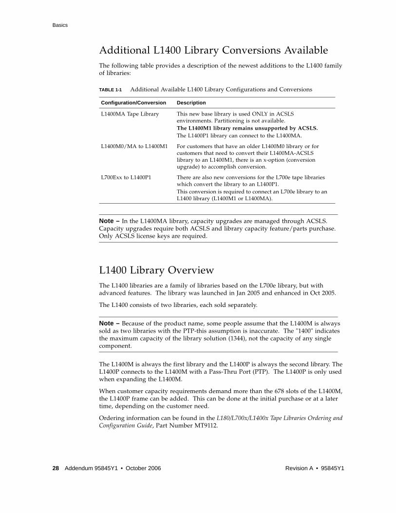
Additional L1400 Library Conversions AvailableThe following table provides a description of the newest additions to the L1400 family of libraries:
Note – In the L1400MA library, capacity upgrades are managed through ACSLS. Capacity upgrades require both ACSLS and library capacity feature/parts purchase. Only ACSLS license keys are required.
L1400 Library OverviewThe L1400 libraries are a family of libraries based on the L700e library, but with advanced features. The library was launched in Jan 2005 and enhanced in Oct 2005.
The L1400 consists of two libraries, each sold separately.
Note – Because of the product name, some people assume that the L1400M is always sold as two libraries with the PTP-this assumption is inaccurate. The "1400" indicates the maximum capacity of the library solution (1344), not the capacity of any single component.
The L1400M is always the first library and the L1400P is always the second library. The L1400P connects to the L1400M with a Pass-Thru Port (PTP). The L1400P is only used when expanding the L1400M.
When customer capacity requirements demand more than the 678 slots of the L1400M, the L1400P frame can be added. This can be done at the initial purchase or at a later time, depending on the customer need.
Ordering information can be found in the L180/L700x/L1400x Tape Libraries Ordering and Configuration Guide, Part Number MT9112.
TABLE 1-1 Additional Available L1400 Library Configurations and Conversions
Configuration/Conversion Description
L1400MA Tape Library This new base library is used ONLY in ACSLS environments. Partitioning is not available.The L1400M1 library remains unsupported by ACSLS. The L1400P1 library can connect to the L1400MA.
L1400M0/MA to L1400M1 For customers that have an older L1400M0 library or for customers that need to convert their L1400MA-ACSLS library to an L1400M1, there is an x-option (conversion upgrade) to accomplish conversion.
L700Exx to L1400P1 There are also new conversions for the L700e tape libraries which convert the library to an L1400P1. This conversion is required to connect an L700e library to an L1400 library (L1400M1 or L1400MA).
28 Addendum 95845Y1 • October 2006 Revision A • 95845Y1

Basics
L1400 Management and Control Function EnhancementsThe L1400 library management/control functions have been enhanced to provide three key features:
■ Partitioning: Native logical partitioning support, enabling tape consolidation.
■ Continuous Capacity Technology: Enables a capacity on demand growth model for quick and easy cartridge slot capacity growth.
■ Aggregation: Native management of the PTP without the need for ACSLS.
95845Y1 • Revision A Chapter 1 L1400 Product Update 29

Basics
30 Addendum 95845Y1 • October 2006 Revision A • 95845Y1

Partitioning
PartitioningPartitioning is an optional feature of the L1400M1 tape library. It is used to share the library with multiple hosts or applications. Partitioning supports tape consolidation projects. Partitioning is available as a feature of the L1400M1 library (feature code: L1400M1-PART) or as a conversion bill (C/B: 102096).
Note – An access key must be requested from the Customer Resource Center (CRC) and entered into the L1400M1 interface management page to enable the partitioning feature.
Partitioning OverviewPartitioning with the L1400M is logical partitioning, performed by the interface control card of the L1400M1 library or the SN3300 of the L1400M0 library. The end user can assign specific cartridge slots, drives, and CAP slots to a partition. The partition is then mapped to a backup application. Each partition is presented to the application as a different L700 library.
Logical Partitioning
When Sun uses the term "logical partitioning" in reference to tape libraries, it refers to how mixed media is supported. Sun Any Cartridge Any SlotTM technology allows us to assign the cartridge cells to a partition without any physical cell restrictions. So the customer can assign these slots to any partition, using any drive technology as they see fit, and they can change these slot assignments quickly, easily, and without disruption-there are no physical components to change.
Other solutions cannot support mixed media and therefore use different "physical" cell arrays to support different media types. Since these arrays are physically different for different technologies, we refer to them as having "physical partitioning". Competitive physical partitioning solutions are less flexible because:
1. They can't support mixed media within a partition.
2. To change a partition a customer may have to open up the library and physically install arrays or swap arrays.
3. Capacity planning becomes more difficult because slot capacity can only be used as it was originally planned-no flexibility.
4. Repurposing the library and using different tape technology is difficult because all the arrays may need to be changed.
Note – Code release 5.8.0c allows partitions to be created and saved without any disruption. Prior to code 5.8.0c the interface card needed to be rebooted (not the library, just the interface card) which would take roughly 32 seconds.
95845Y1 • Revision A Chapter 1 L1400 Product Update 31

Partitioning
How L1400 Logical Partitioning Works
The L1400 allows definition of a maximum of six partitions.
Note – Competitors offer a higher number of partitions, but we rarely see the need for more than 2-3 partitions, so six has been more than enough for our customers.
While the L1400M Partitioning feature enables sharing the library as a whole with multiple applications/hosts, specific resources within the library (Cartridge Slots, Tape Drives, and CAP Slots) cannot be shared. To enable true sharing of these individual assets you must purchase and install ACSLS. If you want to run ACSLS with an L1400 library, you need to order an L1400MA library.
Each partition is presented to backup applications as its own L700 library with a unique SCSI ID. The ID is an 11 character string consisting of three parts:
■ The first three characters always start with "STK"
■ The next six characters are the serial number of the interface card or the SN3300 if it is an L1400M0 library. This serial number is made up of six characters which always begin with "AO", the serial number looks like "A0xxxx"
■ The last two characters indicate the partition number, partitions one through six ("01" through "06).
For example the serial numbers for partitions 1-6 would look like the following:
■ Partition 1: STKA0xxxx01
■ Partition 2: STKA0xxxx02
■ Partition 3: STKA0xxxx03
■ Partition 4: STKA0xxxx04
■ Partition 5: STKA0xxxx05
■ Partition 6: STKA0xxxx06
All hosts connect to the FC port on the library interface control card through a FC switch (the FC switch is not included with the library, customers provide their own switches or one must be ordered separately). Make sure that the library is zoned so all the hosts can see the interface control card. Assignment of partitions to hosts is covered in “Assigning Hosts/Backup Applications to Partitions” on page 43.
Partitioning allows multiple hosts to have access to the same L1400M library via a single FC port on the interface control card. The L1400M interface control card uses LUN management to prevent conflicts, restricting host access to specific partitions by assigning each partition to a different FC LUN. Each host is then presented specific LUN(s) based on the WWN of the host.
For example, one NetBackup host may see LUN 0 (Partition 1) and a TSM host may only see LUN 1 (Partition 2) when they perform discovery on the library. Each partition/LUN in turn is assigned specific library resources (cartridge slots, tape drives, and CAP slots), so the hosts can only see the library resources that are assigned to their partition.
Note – To minimize PTP exchanges, we recommend keeping partitions within a single frame unless size dictates they use resources from the other frame.
32 Addendum 95845Y1 • October 2006 Revision A • 95845Y1

Partitioning
Ordering a Partitioning Access KeyYou must request an access key in order to enable the partitioning feature.
After your sales order is placed in the system, you can request an access key. Keys can be requested by anyone possessing the necessary information to place the request: AE, SE, CSE, the customer, etc.
Request a key by going to the CRC SW licensing site (see link below).
https://www.support.storagetek.com/globalnavigation/support/generalpublic/default.htm
1. Log in to the CRC
2. Click on the "Tools & Services" link
3. Click the "Software Keys" link
4. Click on the "L1400M Key Order Form" link.
FIGURE 1-1 on page 34 shows the L1400M key order form. The fields marked with an asterisk are required fields. TABLE 1-2 describes the form fields:
After the request is placed, a 25 alphanumeric software key will be sent to the e-mail address entered in the form.
Please allow 2 business days for processing. Keys are issued from 7:30am - 3:30pm. For information, questions or to EXPEDITE the Software Keys please call 1-800-436-5554 option 3, or 303-661-7667.
TABLE 1-2 Key Order Form Fields
Field Description
Installer's E-Mail Address This field could be the customer e-mail address as these keys are customer installable
Number of Slots Type in the total number of slots the customer will end with. For example, if the customer was upgrading a 300 slot library and ordering 100 slots, you should type in "400"
Hardware Serial Number If you are ordering a key for an L1400M1 model, type in the serial number of the L1400M1 library. If this request is not for an L1400M1 library, leave blank
Router Serial Number If you are ordering a key for an L1400M0 model, type in the serial number of the SN33000. SN3300 serial numbers are 6 characters and begin with "A0" ("A0xxxx"). If this request is not for an L1400M0 library, leave blank.
New/Upgrade/Partitioning key
■ Select "New" if your request is for a access key and part of a new L1400M library purchase.
■ Select "Upgrade" if your request is for a access key and is a capacity upgrade for an existing L1400M library.
■ Select "Partitioning" is the customer is purchasing the L1400M partitioning feature. Partitioning is discussed in more detail in the L1400 Partitioning FAQ.
95845Y1 • Revision A Chapter 1 L1400 Product Update 33

Partitioning
Note – This process is also used to order additional capacity, aggregation, and/or PTP management.
FIGURE 1-1 L1400M Key Order Form
34 Addendum 95845Y1 • October 2006 Revision A • 95845Y1

Partitioning
Installing a Partitoning Access KeyRefer to the "L1400 Interface Control Module User Guide," P/N 96231Afor complete instructions on connecting to the management interface.
Perform the following steps to install the partitioning access key.
1. Go to the L1400M control interface web management page by typing in the IP address of the interface card.
2. The Main Menu on the left side of the screen (FIGURE 1-2) has an item labeled "Licensing" or "Features". Click on that menu item to view the page where the software keys are entered and all current access is listed.
FIGURE 1-2 L1400 ICM Main Menu.
Note – When you enable partitioning your library will no longer be seen by any hosts until you create a partition(s) and assign it to a host. The process of creating partitions and assigning them to hosts is covered in subsequent sections.
Assigning Library Resources to PartitionsTo begin creating a partition and assigning resources, click on the "Partitioning" item on the Main Menu of the web management interface (see FIGURE 1-3 below).
95845Y1 • Revision A Chapter 1 L1400 Product Update 35
Partitioning
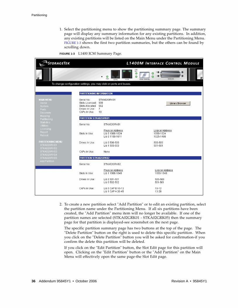
1. Select the partitioning menu to show the partitioning summary page. The summary page will display any summary information for any existing partitions. In addition, any existing partitions will be listed on the Main Menu under the Partitioning Menu. FIGURE 1-3 shows the first two partition summaries, but the others can be found by scrolling down.
FIGURE 1-3 L1400 ICM Summary Page.
2. To create a new partition select "Add Partition" or to edit an existing partition, select the partition name under the Partitioning Menu. If all six partitions have been created, the "Add Partition" menu item will no longer be available. If one of the partition names are selected (STKA02GRK01 - STKA02GRK05) then the summary page for that partition is displayed-see screenshot on the next page.
The specific partition summary page has two buttons at the top of the page. The "Delete Partition" button on the right is used to delete this specific partition. When you click on the "Delete Partition" button you will be asked for confirmation-if you confirm the delete this partition will be deleted.
If you click on the "Edit Partition" button, the Slot Edit page for this partition will open. Clicking on the "Edit Partition" button or the "Add Partition" on the Main Menu will effectively open the same page-the Slot Edit page.
36 Addendum 95845Y1 • October 2006 Revision A • 95845Y1

Partitioning
Note – All library resources (cartridge slots, drives, and CAP slots) are assigned by using the library element addresses; these element addresses are listed in the GUI. There are also element maps in the L700/1400 technical manuals which can be downloaded from the Sun StorageTek Customer Resource Center web site.
FIGURE 1-4 Partition Information Screen
Assigning Cartridge Slots to a PartitionWhen "Add Partition" or "Edit Partition" is selected, the Slot Edit page is displayed (FIGURE 1-5 on page 38). The slots are assigned to a partition by entering the slot element address ranges you want to assign to the partition. You can assign up to 10 element address ranges per partition so your cartridge slots within a partition do not have to be contiguous. Allowing non-contiguous slot assignment allows the customer to grow their partitions without having to reconfigure their library.
In a dual frame installation (L1400M0/M1 and L1400P1) the element ranges are defined by first identifying which library they are from, "Lib 0" or "Lib 1". Generally speaking, the L1400M1 will be Lib 0 and the L1400P will be Lib 1. While slots within a partition can span across libraries, each element range is restricted to one library.
■ Partitions can consist of any number of slots, with a minimum of one
■ Slots can only be assigned to one partition, not shared
■ Slots are only available if assigned to a partition
95845Y1 • Revision A Chapter 1 L1400 Product Update 37
Partitioning
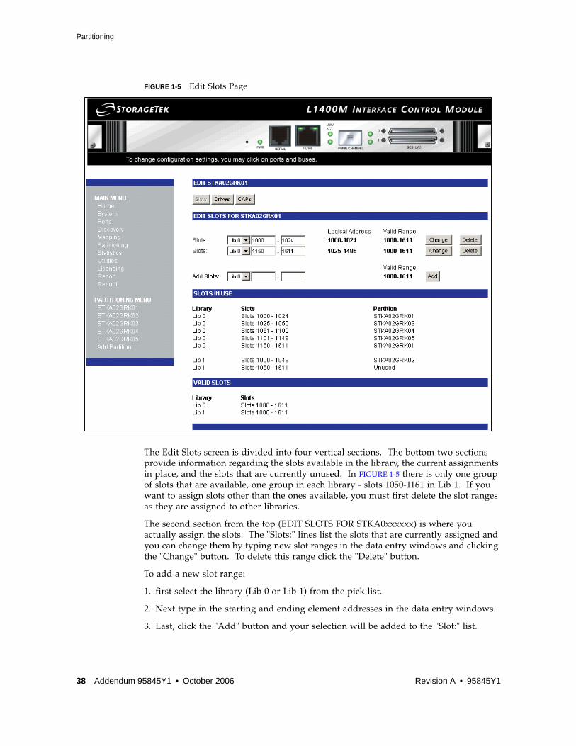
FIGURE 1-5 Edit Slots Page
The Edit Slots screen is divided into four vertical sections. The bottom two sections provide information regarding the slots available in the library, the current assignments in place, and the slots that are currently unused. In FIGURE 1-5 there is only one group of slots that are available, one group in each library - slots 1050-1161 in Lib 1. If you want to assign slots other than the ones available, you must first delete the slot ranges as they are assigned to other libraries.
The second section from the top (EDIT SLOTS FOR STKA0xxxxxx) is where you actually assign the slots. The "Slots:" lines list the slots that are currently assigned and you can change them by typing new slot ranges in the data entry windows and clicking the "Change" button. To delete this range click the "Delete" button.
To add a new slot range:
1. first select the library (Lib 0 or Lib 1) from the pick list.
2. Next type in the starting and ending element addresses in the data entry windows.
3. Last, click the "Add" button and your selection will be added to the "Slot:" list.
38 Addendum 95845Y1 • October 2006 Revision A • 95845Y1

Partitioning
To edit an existing allocation simply edit the existing slot range and click "Change". Making any slots allocation changes causes two new buttons to be displayed on the screen (FIGURE 1-6): "Revert to Saved" and "Save Changes". Use the "Save Changes" to save the changes you have made, use the "Revert to Saved" to cancel you changes and revert back to the last saved allocation.
FIGURE 1-6 Save Changes Page
Note – Element addresses are entered in ranges: the first window is the starting address, the second window is the ending address. To assign only one slot, enter the same element address in both windows.
When you are finished editing slot allocations to this partition and have saved your changes, you can continue editing drives and CAPs for this partition by clicking the "Drives" or "CAPs" buttons at the top of the page or move to any other Menu item on the left side of the screen.
95845Y1 • Revision A Chapter 1 L1400 Product Update 39

Partitioning
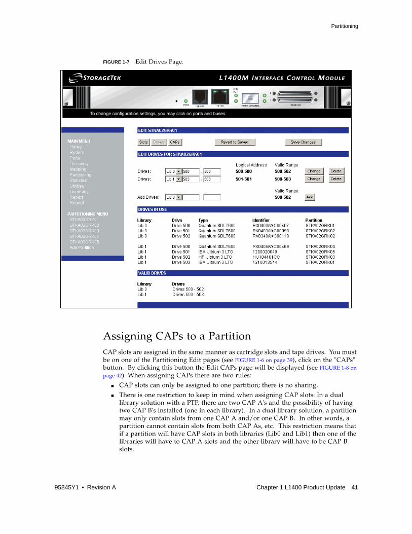
Assigning Drives to a PartitionYou must be on one of the Partitioning Edit pages (see FIGURE 1-6 on page 39), click on the "Drives" button. By clicking this button the Edit Drives page will be displayed (see FIGURE 1-7 on page 41.). When assigning drives there are two rules:
■ Any number of drives can be assigned to a partition.
■ Drives cannot be shared with more than one partition.
Note – "L1400M1 Partitioning is implemented in the control path only. Within the control path, drives can only be seen by the hosts/applications assigned to the same partition as the drives. Partitioning is not executed in the data path, so any host can see any drive-but they can only issue control commands to their drives. Restricting data ath access to the drives can be accomplished by zoning the switch.
The Edit Drives page is structured in the same way as the Edit Slots page, with four sections (see “Assigning Cartridge Slots to a Partition” on page 37). The bottom two sections display the drive resources summaries, listing what is installed in the library and their current assignments. The "DRIVES IN USE" section provides the information you need to make drive assignments. The "Drives" column provides the element address of each drive installed in the library. The "Identifier" column lists the drive serial numbers, and the "Partition" column identifies the drive's current assignment.
The "EDIT DRIVES FOR STKA0xxxxxx" section (second section from the top) is where you actually assign drives or edit current assignments. You make these assignments by typing in drive element addresses in the "Add Drives:" data entry windows. Click the "Add" button after you have entered the drive element addresses. Edit current drive assignments by changing the element addresses and clicking the "Change" button. Delete a drive assignment by clicking the "Delete" button.
Making any drive allocation changes causes two new buttons to be displayed on the screen (see FIGURE 1-7 on page 41): "Revert to Saved" and "Save Changes". Use the "Save Changes" to save the changes you have made, use the "Revert to Saved" to cancel you changes and revert back to the last saved allocation.
The entry for element addresses are in ranges: the first window is the starting address, the second window is the ending address. To assign only one drive, enter the same element address in the both windows. As with cartridge slots, you can enter up to 10 element ranges for drives for each partition.
Note – While all the drives element addresses do not need to be sequentia,l it is not recommended to use one range for each drive as this would artificially limit the partition to only 10 drives.
When you are finished editing drive assignments to this partition and have saved your changes, you can continue editing slots and CAPs for this partition by clicking the "Slots" or "CAPs" buttons at the top of the page or move to any other Menu item on the left side of the screen.
40 Addendum 95845Y1 • October 2006 Revision A • 95845Y1
Partitioning
FIGURE 1-7 Edit Drives Page.
Assigning CAPs to a PartitionCAP slots are assigned in the same manner as cartridge slots and tape drives. You must be on one of the Partitioning Edit pages (see FIGURE 1-6 on page 39), click on the "CAPs" button. By clicking this button the Edit CAPs page will be displayed (see FIGURE 1-8 on page 42). When assigning CAPs there are two rules:
■ CAP slots can only be assigned to one partition; there is no sharing.
■ There is one restriction to keep in mind when assigning CAP slots: In a dual library solution with a PTP, there are two CAP A's and the possibility of having two CAP B's installed (one in each library). In a dual library solution, a partition may only contain slots from one CAP A and/or one CAP B. In other words, a partition cannot contain slots from both CAP As, etc. This restriction means that if a partition will have CAP slots in both libraries (Lib0 and Lib1) then one of the libraries will have to CAP A slots and the other library will have to be CAP B slots.
95845Y1 • Revision A Chapter 1 L1400 Product Update 41

Partitioning
FIGURE 1-8 Edit Cartridge Access Port Page
The CAP Partitioning page (FIGURE 1-8) is structured in the same way as the other Partitioning pages, with four sections.
The bottom two sections provide information on the current CAP slots and their assignments. The "CARTRIDGE ACCESS PORTS IN USE" section identifies which CAP slots are available. The "VALID CARTRIDGE ACCESS PORTS" list the physical CAP slots that are installed.
To add a new CAP slot range:
1. first select the library (Lib 0 or Lib 1) from the pick list
2. Select the CAP from the pick list (CAP A or CAP B).
3. Type in the starting and ending element addresses of the CAP slots in the data entry windows.
4. Last, click the "Add" button and your selection will be added to the "CAPs:" list.
Making any CAP allocation changes causes two new buttons to be displayed on the screen (see FIGURE 1-8): "Revert to Saved" and "Save Changes". Use the "Save Changes" to save the changes you have made, use the "Revert to Saved" to cancel you changes and revert back to the last saved allocation.
42 Addendum 95845Y1 • October 2006 Revision A • 95845Y1
Partitioning
The entry for element addresses are in ranges: the first window is the starting address, the second window is the ending address. To assign only one slot, enter the same element address in the both windows. Each partition can have up to 10 element address ranges to assign CAP slots; 10 ranges are more than enough for CAPs.
When you are finished editing CAP assignments to this partition and have saved your changes you can continue editing slots and drives for this partition by clicking the "Slots" or "Drives" buttons at the top of the page or move to any other Menu item on the left side of the screen.
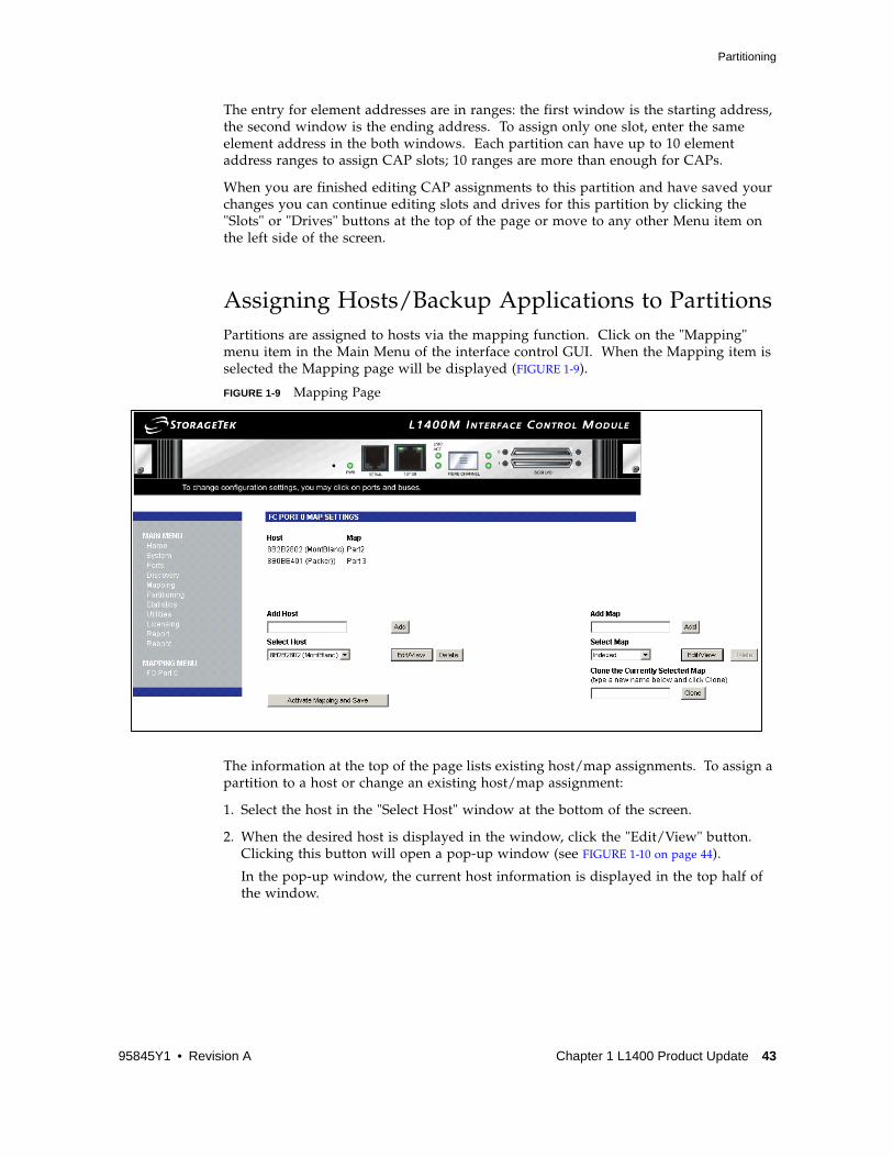
Assigning Hosts/Backup Applications to PartitionsPartitions are assigned to hosts via the mapping function. Click on the "Mapping" menu item in the Main Menu of the interface control GUI. When the Mapping item is selected the Mapping page will be displayed (FIGURE 1-9).
FIGURE 1-9 Mapping Page
The information at the top of the page lists existing host/map assignments. To assign a partition to a host or change an existing host/map assignment:
1. Select the host in the "Select Host" window at the bottom of the screen.
2. When the desired host is displayed in the window, click the "Edit/View" button. Clicking this button will open a pop-up window (see FIGURE 1-10 on page 44).
In the pop-up window, the current host information is displayed in the top half of the window.
95845Y1 • Revision A Chapter 1 L1400 Product Update 43

Partitioning
FIGURE 1-10 Host Port Information Window
3. If you want to make any changes to the host information, make the changes in the "Modify Host Information" section.
Note – Often the end user will want to add a more user friendly name to the end of the "Host Name".
4. To add a partition to this host simply click on the "Map Name" pick list and all of the partitions you have created will appear. When a partition is created through the process defined in the previous sections, a "map" is automatically created as well. The default mapping is one partition to one map. These "partition maps" are listed by the partition name ("STKA0xxxxxx"). Select the partition you wish to assign from the list.
5. When you have completed any host information changes and selected your partition, click the "Modify" button and the window will close.
44 Addendum 95845Y1 • October 2006 Revision A • 95845Y1

Partitioning
6. To finalize your host/partition mapping, click the "Activate Mapping and Save" button located on the bottom of the Mapping page. At this point you have completed the entire partitioning creation and assignment process.
Users can create more complex maps, as needed.
Note – Refer to the documentation on the Customer Resource Center for more information about creating and changing maps. This document only describes a simple mapping exercise.
Changing the Default MapsOn the right side of the Mapping Page is the area where you can create and modify maps (see FIGURE 1-9 on page 43).
To add a new map, type in the name of the new map in the "Add Map" data entry window and click the "Add" button. Then Select the newly created map in the "Select Map" pick list and click on the "Edit/View" button; then the edit map pop-up window will appear (FIGURE 1-11 on page 46). Edit the map information as appropriate, then click the "Activate Mapping Changes" button on the Mapping page.
Editing the Default Partition MapsThe "partition maps" can be viewed by clicking the "Select Map" selection on the right side of the Mapping page. By clicking on the "Select Map" drop down list, a list of the current maps will be displayed. The default names for partition maps one through six are STKA0xxxx01 through STKA0xxxx06.
1. Select the partition map you want to edit and click the "Edit/View" button, the Edit/View Map pop-up window will appear (see FIGURE 1-11).
2. Edit the information as needed. When finished, click the "Activate Mapping Changes" button on the Mapping page.
95845Y1 • Revision A Chapter 1 L1400 Product Update 45

Partitioning
FIGURE 1-11 Edit/View Map Window
Partitioned Element Address PresentationThe L1400 libraries use the same physical element addressing as the L700e. The physical addresses are well documented within the L700/1400 technical manuals located on the CRC, but the physical addresses for the L1400 are as follows:
■ Medium Transport Element (Robot or Changer) is 0
■ Storage Elements (Cartridge Slots)
■ Begins at 1000
■ Max slot configuration ends at 1677
■ Data Transfer Elements (Tape Drives) starts at 500
■ Begins at 500
■ Max drive configuration ends at 519
■ Import/Export Elements (CAP slots)
46 Addendum 95845Y1 • October 2006 Revision A • 95845Y1

Partitioning
■ Single CAP: CAP-A, 10 - 29
■ Two CAPs: CAP-A, 30-49 ; CAP-B, 10 - 29
The partition element addresses are referred to as "logical" addresses, and the physical library's element addresses as "physical" addresses. Each partition always begins the logical element addressing by using the L1400 base physical addresses for each element type. Each partition begins its logical addressing with the following addresses:
■ Medium Transport Element (Robot or Changer) is 0
■ Storage Elements (Cartridge Slots) starts at 1000 (0x3e8)
■ Data Transfer Elements (Tape Drives) starts at 500 (0x1f4)
■ Import/Export Elements (CAP slots) starts at 10 (0xa)
The element addresses are then incremented up by the number of elements being addressed. TABLE 1-3 below provides an example of a single frame L1400M1 library with four partitions.
The L1400M interface controller keeps a translation map that can translate the logical addresses contained in Changer commands received by each virtual Changer LUN to the correct physical address of the assigned elements in the physical library (according to the partitioning resource assignments). Responses from the physical library (to commands sent to the library - e.g. Read Element Status) have to have the physical element addresses contained in them "mapped" back to "logical" element addresses.
In an aggregated environment (L1400M1/L1400P1 with a PTP), another layer of addressing is needed to manage the physical addresses of the L1400P1 library -- an aggregated layer. The physical addresses of the L1400P1 library are exactly the same as the physical addresses of the L1400M1 library. Host applications cannot manage these duplicate addresses; these applications need one sequential addressing scheme.
TABLE 1-3 Example: Physical Address / Logical Partition Address
PartitionPhysical Address
of Tape LibraryLogical Partition AddressPresented to Application
Partition #1Cart. Slots
Tape DrivesCAP Slots
01000-1199500-501
10-14
01000-1199500-501
10-14
Partition #2Cart. Slots
Tape DrivesCAP Slots
01200-1299
50215-19
01000-1099
50010-14
Partition #3Cart. Slots
Tape DrivesCAP Slots
01300-1399, 1450-1677
503-50820-27
01000-1327
500-50510-17
Partition #4Cart. Slots
Tape DrivesCAP Slots
01400-1499
50928-29
01000-1049
50010-11
95845Y1 • Revision A Chapter 1 L1400 Product Update 47

Partitioning
To create one sequential address scheme across the L1400M1/L1400P1 libraries, the interface controller appends the L1400P1 physical addresses of each element type to those in the first frame, creating one contiguous group of element addresses. Thus there is an additional translation of element addresses in the L1400P1, the aggregated physical address layer.
In an aggregated environment, the physical cartridge slot addresses of the L400M1 run from 1000 - 1671, and the aggregated slot addresses of the L1400P1 run from 1672 - 2343. These aggregated slot addresses are what is presented to the application. To the host application it looks like one contiguous address space from 1000 - 2343. This extra layer of aggregation is a potential cause for confusion as partitioning resource assignments in the GUI still use the true physical addresses and are differentiated by a "Lib 0" and "Lib 1" qualifier.
You can see the translation of the logical and aggregated addresses to physical address by going to the "Capacity Mgmt" page or the "Partitioning" page and clicking the "Library Browser button.
Address Translation TableA translation table for logical to physical/aggregated addresses is available for interface control cards with 5.8.0c code or later.
1. On the Main Menu, click on the "Capacity Mgmt" menu item; the Capacity Mgmt page will display (FIGURE 1-12).
FIGURE 1-12 Capacity Management Information Page.
2. Clicking on the "Library Browser" button will open a pop-up window that displays detailed addressing information; see FIGURE 1-13 on page 50. The information contained in the "Library Browser" is divided by tabs, there are two main tab's, one for each physical library, and four tabs under each library tab:
48 Addendum 95845Y1 • October 2006 Revision A • 95845Y1

Partitioning
■ Slots
■ Drives
■ CAPs
■ PTP
Each of these tabs provide information listed in TABLE 1-4.
TABLE 1-4 Address Translation Window Information Tabs
Tab Description
Address the physical address
Vol Tag volser of the cartridge in this slot
Media Type the type of media in this slot
Src Address the address of the element that the tape was in before it was moved to the current location. Usually the information tells you what slot a tape normally is in when it is currently in a drive-the tape might be in element 500 (a drive) with a source address of 1010 (a slot, the normal home for the tape)
Partition provides the logical address presented to the host
95845Y1 • Revision A Chapter 1 L1400 Product Update 49

Partitioning
FIGURE 1-13 Address Translation Window
50 Addendum 95845Y1 • October 2006 Revision A • 95845Y1
Continuous Capacity
Continuous CapacityContinuous Capacity technology is used to provide a capacity-on-demand model for cartridge slot capacity. It provides an easy and flexible way to grow cartridge capacity.
In the L1400 libraries there is a difference between physical cartridge slot capacity and accessible cartridge slot capacity. All L1400 libraries ship with the maximum physical slot capacity installed, but not all of these slots are usable by the customer.
Capacity beyond the default number of cartridge slots is ordered in 100 slot increments.
Capacity upgrades within a library frame are non-disruptive. There is a disruption when the second frame and PTP are installed after the first frame is in use.
Note – Depending on the controller code level installed, there may be a brief 32 second outage for each capacity upgrade installed:
Customers using code level 5.8.0c and higher can upgrade capacity non-disruptively.
Code levels lower than 5.8.0c need to reboot the interface control card after the capacity key is enabled. This reboot process for this code level is quick (roughly 32 seconds) and should not cause problems in this customer base.
The default process is to sequentially add capacity based on the physical element address. If this default method is followed, then nothing else needs to be done, and the capacity will automatically be released when the key is "Added".
If you want to choose specific non-sequential physical slots, then after each capacity key that is entered you must use the Capacity Management menu item to allocate the slots used. This user allocation is required if any previous slots are out of sequence.
If you assign slots that are out of sequence, a new addressing scheme will be used to present the slot element addresses to the host application. These logical addresses are explained in more detail in section “Continuous Capacity Cartridge Slot Presentation” on page 57.
Ordering a Capacity Access KeyYou must request an access key in order to release access to physical slots within the L1400 libraries.
After your sales order is placed in the system, you can request an access key. Keys can be requested by anyone possessing the necessary information to place the request: AE, SE, CSE, the customer, etc.
Note – You must request an access key in order to gain access beyond 200 slots. Even with new library orders, keys must be requested.
Request a key by going to the CRC SW licensing site (see link below).
95845Y1 • Revision A Chapter 1 L1400 Product Update 51

Continuous Capacity
https://www.support.storagetek.com/globalnavigation/support/generalpublic/default.htm
1. Log in to the CRC
2. Click on the "Tools & Services" link
3. Click the "Software Keys" link
4. Click on the "L1400M Key Order Form" link.
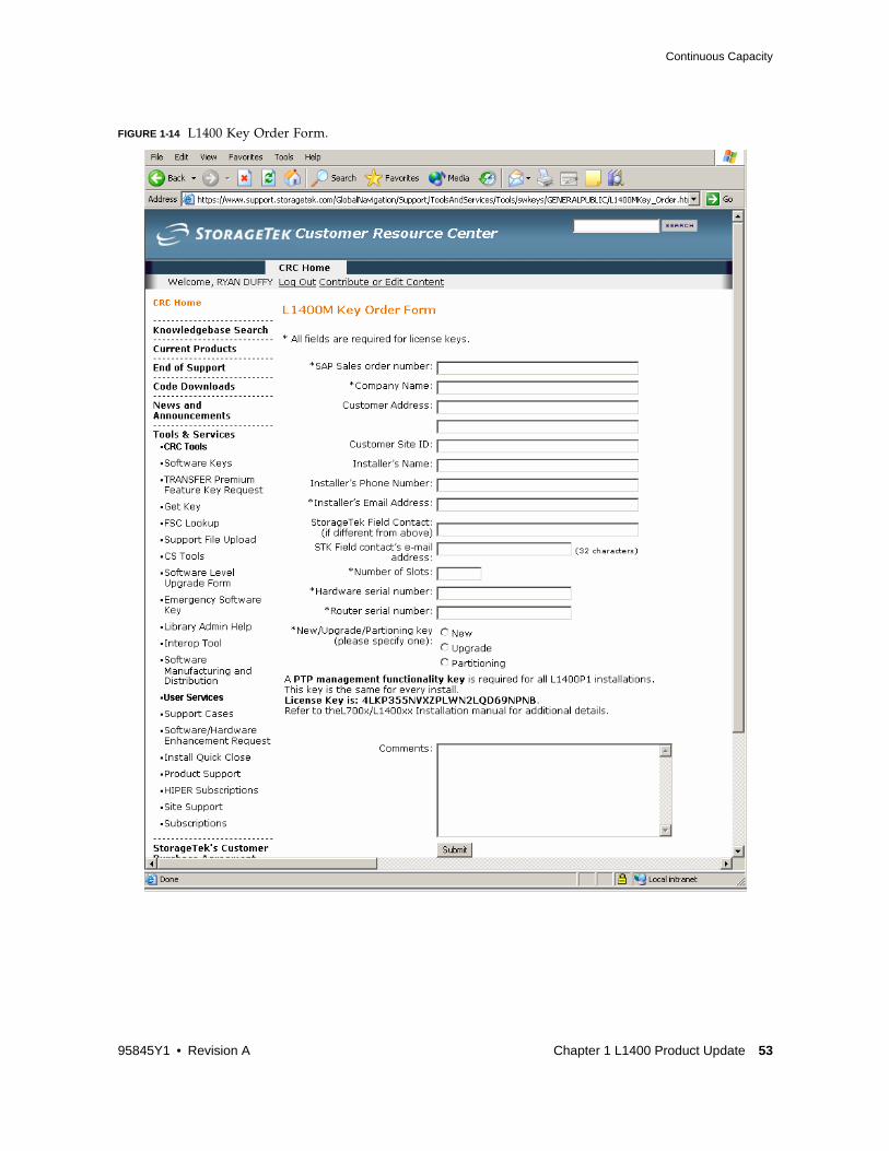
FIGURE 1-14 on page 53 shows the L1400M key order form. The fields marked with an asterisk are required fields. TABLE 1-5 describes the form fields:
After the request is placed, a 25 alphanumeric software key will be sent to the e-mail address entered in the form.
Please allow 2 business days for processing. Keys are issued from 7:30am - 3:30pm. For information, questions or to EXPEDITE the Software Keys please call 1-800-436-5554 option 3, or 303-661-7667.
Note – This process is also used to order partitioning, aggregation, and/or PTP management.
TABLE 1-5 Key Order Form Fields
Field Description
Installer's E-Mail Address This field could be the customer e-mail address as these keys are customer installable
Number of Slots Type in the total number of slots the customer will end with. For example, if the customer was upgrading a 300 slot library and ordering 100 slots, you should type in "400"
Hardware Serial Number If you are ordering a key for an L1400M1 model, type in the serial number of the L1400M1 library. If this request is not for an L1400M1 library, leave blank
Router Serial Number If you are ordering a key for an L1400M0 model, type in the serial number of the SN33000. SN3300 serial numbers are 6 characters and begin with "A0" ("A0xxxx"). If this request is not for an L1400M0 library, leave blank.
New/Upgrade/Partitioning key
■ Select "New" if your request is for a access key and part of a new L1400M library purchase.
■ Select "Upgrade" if your request is for a access key and is a capacity upgrade for an existing L1400M library.
■ Select "Partitioning" is the customer is purchasing the L1400M partitioning feature. Partitioning is discussed in more detail in the L1400 Partitioning FAQ.
52 Addendum 95845Y1 • October 2006 Revision A • 95845Y1
Continuous Capacity
FIGURE 1-14 L1400 Key Order Form.
95845Y1 • Revision A Chapter 1 L1400 Product Update 53

Continuous Capacity
Installing a Capacity Access KeyRefer to the "L1400 Interface Control Module User Guide," P/N 96231A for complete instructions on connecting to the management interface.
Perform the following steps to install the capacity access key.
1. Go to the L1400M control interface web management page by typing in the IP address of the interface card.
2. The Main Menu on the left side of the screen (FIGURE 1-15) has an item labeled "Licensing" or "Features". Click on that menu item to view the page where the software keys are entered and all current access is listed.
3. Enter the software key in the "Enter Key" data entry window and click on the "Add" button.
FIGURE 1-15 L1400 ICM Main Menu
Note – After adding capacity, a reboot is only necessary for code levels below 5.8.0c.
After the capacity key is entered, the access to the slots is released.
54 Addendum 95845Y1 • October 2006 Revision A • 95845Y1

Continuous Capacity
Allocating Capacity1. On the Main Menu, click on the "Capacity Mgmt" item. The Capacity Management
page is displayed as shown in FIGURE 1-16, below.
This page shows the slots, drives, and CAPs that are in use; both the physical and logical addresses are displayed.
FIGURE 1-16 Capacity Management Page.
2. To allocate new capacity, click on "Edit Capacity Management." the Edit Capacity Management page is displayed as shown in FIGURE 1-17 on page 56, below.
This page will display the slots ranges that are currently assigned. Up to 10 slot ranges can be used to assign capacity.
Note – Element addresses are entered in ranges: the first window is the starting address, and the second window is the ending address. To assign only one slot, enter the same element address in the both windows.
3. To add a new slot range:
a. Select the library (Lib 0 or Lib 1) from the pick list; Lib 1 will only be displayed if the Aggregation feature is enabled and the L1400P1 library has been installed.
b. Next type in the starting and ending element addresses in the data entry windows.
c. Last, click the "Add" button and your selection will be added to the "Slot:" list.
Note – To edit an existing allocation simply edit the existing slot range and click "Change". To delete a range, click the corresponding "Delete" button.
95845Y1 • Revision A Chapter 1 L1400 Product Update 55

Continuous Capacity
FIGURE 1-17 Edit Capacity Management Page.
4. Making any slot allocation changes causes two new buttons to be displayed on the screen (see FIGURE 1-18): "Revert to Saved" and "Save Changes".
Use the "Save Changes" to save the changes you have made, use the "Revert to Saved" to cancel changes and revert back to the last saved allocation.
FIGURE 1-18 “Save Changes” Page.
56 Addendum 95845Y1 • October 2006 Revision A • 95845Y1

Continuous Capacity
Continuous Capacity Cartridge Slot PresentationThe L1400 libraries use the same physical element addressing as the L700e. The physical addresses are well documented within the L700/1400 technical manuals located on the CRC, but the physical addresses for the L1400 are as follows:
■ Medium Transport Element (Robot or Changer) is 0
■ Storage Elements (Cartridge Slots)
■ Begins at 1000
■ Max slot configuration ends at 1677
■ Data Transfer Elements (Tape Drives) starts at 500
■ Begins at 500
■ Max drive configuration ends at 519
■ Import/Export Elements (CAP slots)
■ Single CAP: CAP-A, 10 - 29
■ Two CAPs: CAP-A, 30-49 ; CAP-B, 10 - 29
Logical addresses are needed anytime the physical address cannot be used. SCSI element address must be sequential and if the physical addresses are not sequential, due to non-sequential slots being allocated in the Capacity Management page or due to the L1400P1 library being installed. In these cases a logical address is used to keep the slot presentation to the host application sequential.
When logical addresses are used, the addressing scheme still begins at the starting points of the physical addresses listed below.
■ Medium Transport Element (Robot or Changer) is 0
■ Storage Elements (Cartridge Slots) starts at 1000 (0x3e8)
■ Data Transfer Elements (Tape Drives) starts at 500 (0x1f4)
■ Import/Export Elements (CAP slots) starts at 10 (0xa)
Then the element addresses are incremented up by the number of elements being addressed. TABLE 1-6 below provides an example of a dual frame L1400M1/L1400P1 library with a single CAP in each frame, 27 tape drives, and a 900 slot license.
The physical addresses of the L1400P1 library are exactly the same as the physical addresses of the L1400M1 library. Host applications cannot manage these duplicate addresses, these applications need one sequential addressing scheme.
TABLE 1-6 Physical Address / Logical Partition Address
PartitionPhysical Address
of Tape LibraryLogical Partition AddressPresented to Application
L1400M1Cart. Slots
Tape DrivesCAP Slots
01000-1611500-519
10-29
01000-1611500-519
10-29
L1400P1Cart. Slots
Tape DrivesCAP Slots
01000-1287
500-50610-29
N/A1612-1899
520-52630-49
95845Y1 • Revision A Chapter 1 L1400 Product Update 57

Continuous Capacity
To create one sequential address scheme across the L1400M1/L1400P1 libraries, the interface controller appends the L1400P1 physical addresses of each element type to those in the first frame, creating one contiguous group of element addresses. Thus, there is an additional translation of element addresses in the L1400P1. This is the aggregated physical address layer.
In an aggregated environment, the physical cartridge slot addresses of the L400M1 run from 1000 - 1671, and the aggregated slot addresses of the L1400P1 run from 1672 - 2343. These aggregated slot addresses are what is presented to the application. To the host application it appears as one contiguous address space from 1000 - 2343. This extra layer of aggregation is a potential cause for confusion as partitioning resource assignments in the GUI still use the true physical addresses and are differentiated by a "Lib 0" and "Lib 1" qualifier.
The L1400M interface controller keeps a translation map that can translate the logical addresses contained in Changer commands received by each virtual Changer LUN to the correct physical address of the assigned elements in the physical library (according to the partitioning resource assignments). Responses from the physical library (to commands sent to the library - e.g. Read Element Status) have to have the physical element addresses contained in them "mapped" back to "logical" element addresses.
You can see the translation of the logical and aggregated addresses to physical address by going to the "Capacity Mgmt" page-they will be listed in the columns "Physical Address" and "Logical Address" (see screenshot below). For additional information click the "Library Browser" button.
Address Translation TableA translation table of the logical to physical/aggregated addresses is available for interface control cards with 5.8.0c code or later.
1. On the Main Menu, click on the "Capacity Mgmt" menu item; the Capacity Mgmt page will display (FIGURE 1-19 on page 59).
58 Addendum 95845Y1 • October 2006 Revision A • 95845Y1

Continuous Capacity
FIGURE 1-19 Capacity Management Information Page.
2. Clicking on the "Library Browser" button will open a pop-up window that displays detailed addressing information; see FIGURE 1-20 on page 60.
At the top there are the library tabs:
■ If an L1400MA library is installed as a single frame, only the "Lib 0" tab is displayed.
■ If an L1400M1 library is installed with an L1400P1 library (dual frame with PTP), both the "Lib 0" and the "Lib 1" tabs are displayed.
Generally speaking, the L1400M1 = Lib 0 and the L1400P1 = Lib 1. Each "Lib #" tab displays the same sub-tabs:
a. Slots: Slots sub-tabs provide information listed in TABLE 1-7 on page 60.
b. Drives: Drives sub-tabs provide information listed in TABLE 1-8 on page 61, and are shown in FIGURE 1-21 on page 61
c. CAPs: CAP sub-tabs provide information listed in TABLE 1-9 on page 62, and are shown in FIGURE 1-22 on page 62
d. PTP: sub-tabs provide information listed in TABLE 1-10 on page 63, and are shown in FIGURE 1-23 on page 63
95845Y1 • Revision A Chapter 1 L1400 Product Update 59

Continuous Capacity
FIGURE 1-20 Address Translation Window, Slots Tab
.
TABLE 1-7 Address Translation Window, Slots Tabs
Tab Description
Address the physical address
Vol Tag volser of the cartridge in this slot
Media Type the type of media in this slot
Src Address the address of the element that the tape was in before it was moved to the current location. Usually the information tells you what slot a tape normally is in when it is currently in a drive-the tape might be in element 500 (a drive) with a source address of 1010 (a slot, the normal home for the tape)
In Use provides the logical address presented to the host-this column is labeled "Partitioning" when the Partitioning feature is enabled.
60 Addendum 95845Y1 • October 2006 Revision A • 95845Y1

Continuous Capacity
FIGURE 1-21 .Address Translation Window, Drives Tab.
TABLE 1-8 Address Translation Window, Drive Tabs
Tab Description
Address the physical address of the drives
Drive Type the drive manufacturer technology type of the drive
Id the drive serial number
Vol Tag the volser of the media in the drive; only displays if media is in the drive
Media Type the type of media in the drive; only displays if media is in the drive.
Src Addr the source address (usually a slot address) of the cartridge currently in the drive
95845Y1 • Revision A Chapter 1 L1400 Product Update 61

Continuous Capacity
FIGURE 1-22 Address Translation Window, CAPs Tab.
.
TABLE 1-9 Address Translation Window, CAPs Tabs
Tab Description
Address the physical address of the CAP slots
Vol Tag the volser of the media in the CAP; only displays if media is in the CAP
Media Type the type of media in the CAP; only displays if media is in the CAP.
Src Addr the source address (usually a slot address) of the cartridge currently in the CAP
62 Addendum 95845Y1 • October 2006 Revision A • 95845Y1

Continuous Capacity
FIGURE 1-23 Address Translation Window, PTP Tabs.
.
Moving Media, Single Library
Caution – Moving media outside the host application can cause serious problems with the application. We strongly recommend using the host application for any media movement needs.
When the "Move…" button is clicked on any library browser page, the “Move Media” pop-up window appears (FIGURE 1-24 on page 64). Notice the same "Lib 0" and "Lib 1" tabs as in the other library browser windows. The "Lib 1" tab only displays if the L1400P1 is installed.
TABLE 1-10 Address Translation Window, PTP Tabs
Tab Description
Address the physical address of the PTP slots
Vol Tag the volser of the media in the PTP; only displays if media is in the PTP
Media Type the type of media in the PTP; only displays if media is in the PTP.
Src Addr the source address (usually a slot address) of the cartridge currently in the PTP
95845Y1 • Revision A Chapter 1 L1400 Product Update 63

Continuous Capacity
FIGURE 1-24 Move Media Window.
1. Select the library where the media resides (Lib 0 or Lib 1).
a. Click on the "Move From Addresses:" pick list and select the location of the media you wish to move from the list of Slots, Drives, CAPs, and PTP.
The valid physical element address ranges will appear on the far right.
b. Enter the element address ranges of the media you wish to move in the windows.
To move multiple pieces of media at once enter the starting address in the first window and the ending address in the second window.
To move a single piece of media, enter the same address in both windows.
c. Select the "Move To Addresses:" select target addresses in the same manner as the "from" addresses were selected. Make sure the target addresses are empty by checking the destination with library browser.
2. Click on the "Submit Move" button. A confirmation window appears (FIGURE 1-25). Click "OK."
Note – If there is a problem with your request, such as the destination address being full, the request will fail. If the address ranges do not match, an error message will display.
A message at the bottom of the Move Media window tracks the move progress. When the move is complete the message will read "No moves in progress."
Clicking the "Cancel" button returns you to the Move Media window, and the move is not executed.
FIGURE 1-25 Confirmation Window.
64 Addendum 95845Y1 • October 2006 Revision A • 95845Y1

Continuous Capacity
Moving Media with the Pass-Thru PortMoving media across the PTP to the other library is accomplished by executing two separate moves.
Note – Before you start, make sure the PTP slots are available using the library browser.
1. Move the media from the source library to the PTP (you can only move two pieces of media at on time to the PTP).
2. After the move to the PTP is completed, click on the target library tab and move the media from the PTP to the destination cell addresses.
95845Y1 • Revision A Chapter 1 L1400 Product Update 65

Continuous Capacity
66 Addendum 95845Y1 • October 2006 Revision A • 95845Y1


SUN™ THE NETWORK IS THE COMPUTER ©2006 Sun Microsystems, Inc. All rights reserved. Sun, Sun Microsystems, and the Sun logo are trademarks or registered trademarks of Sun Microsystems, Inc. in theUnited States and other countries.
Sun Microsystems, Inc. 4150 Network Circle, Santa Clara, CA 95054 USA Phone 1-650-960-1300 or 1-800-555-9SUN Web sun.com
ARGENTINA: 5411-4317-5636 • AUSTRALIA: 1-800-550-786 • AUSTRIA: 43-1-601-26-0 • BALKANS: 301-6188-111 • BELGIUM: 32 2-704 89 83 • BRAZIL: 55-11-51872100 • BRUNEI: 65-216-8333 • CANADA: 1-800-422-8020 (GENERAL); 416-964-2001 (LEARNING MANAGEMENT SYSTEM SALES,TORONTO) • CHILE: 562-372-4500 • COLOMBIA: 571-629-2323CZECH REPUBLIC: 420 2 33009311 • DENMARK: 45 4556 5040 • EGYPT: 00 202 570 9442 • FINLAND: 358-9-525-561 • FRANCE: 33-1-41-33-17-17 • GERMANY: 49-89-460-08-2788 • GREECE: 30-01-6188101 • HONG KONG: 852-2877-7077 • HUNGARY: 361-202-4415 • INDIA: 91-80-229-8989 • INDONESIA: 65-216-8333 • IRELAND: 353-1-668-4377ISRAEL: 972-9-9710500 • ITALY: 39-02-9259511 • JAPAN: 81-3-5779-1820 • KOREA: 82-2-3453-6602 • MALAYSIA: 603-2116-1887 • MIDDLE EAST: 00 9714 3366333 • MEXICO: 525-261-0344 • NETHERLANDS: 31-33-4515200 • NEW ZEALAND: 0800-786-338 • NORTH WEST AFRICA: 00 9714 3366333 • NORWAY: FROM NORWAY: 47-22023950, TO NORWAY:47-23369650 • PAKISTAN: 00-9714-3366333 • PEOPLE'S REPUBLIC OF CHINA: 8610-6803-5588 • PHILIPPINES: 632-885-7867 • POLAND: 48-22-8747848 • PORTUGAL: 351-21-413-4000 • RUSSIA: 7-095-935-8411 • SAUDI ARABIA: 00 9714 3366333 • SINGAPORE: 65-216-8300 • SOUTH AFRICA: 27-11-256-6300 • SPAIN: 34-902-210-412 • SRI LANKA:65-2168333 • SWEDEN: 46-8-631 22 00 • SWITZERLAND: 41-1-908-90-50 (GERMAN) 41-22-999-0444 (FRENCH) • TAIWAN: 886-2-25185735 • THAILAND: 662-344-6855 • TURKEY: 90 212 335 22 00 • UNITED KINGDOM: 44-1276-416-520 • UNITED STATES: 1-800-422-8020 • VENEZUELA: 582-905-3800 • VIETNAM: 65-216-8333 • WORLDWIDE
HEADQUARTERS: 1-650-960-1300