stormwater bmp design supplement for cold climates · pdf filestormwater bmp design supplement...
TRANSCRIPT

Stormwater BMP DesignSupplement for Cold Climates
December 1997
for: US EPA Office of Wetlands, Oceans and Watershedsand US EPA Region 5
by: Deb Caraco and Richard ClaytorCenter for Watershed Protection8391 Main StreetEllicott City, MD [email protected]

Preface Many communities nationwide have adopted urban stormwater quality requirements, resulting in the need to implement stormwater best management practices (BMPs) under many different physical and climatic conditions. The engineering community has expressed concern over how these structures perform in cold or snowy climates. This manual addresses some of the unique challenges in cold climates and makes design recommendations for BMPs to make them more effective in cold regions. Chapter 1 is the background of the report, and gives general guidance. First, it describes the telephone and write-in surveys that provided much of the background information for the manual. It also includes maps that can be used to identify cold and snowy climate regions. Next, it outlines the specific challenges of cold climates, and how they can affect BMP performance. Finally, a matrix of the applicability of BMPs to cold climates is presented, and the reader is referred to other chapters for specific design recommendations. Chapter 2 presents modified sizing criteria for cold climates. These criteria address both water quality and water quantity sizing. The physical basis behind these modifications is the changes in the hydrologic cycle and pollutant loadings that occur in cold climates. Specifically, much of the annual runoff occurs during a short period when the snowpack melts and rain-on-snow events can produce large runoff volumes. Chapters 3 through 7 provide specific cold climate design criteria five basic BMP groups. These include ponds, wetlands, infiltration systems, filtering systems and open channel systems. For each BMP group, specific types of BMPs within the group are described. “Base” criteria, which apply to both moderate and cold climates are presented. The cold climate modifications for each BMP follow. BMPs can be modified in up to six categories, including: feasibility, conveyance, pretreatment, treatment, maintenance and landscaping (See Table 1).
TABLE 1 CATEGORIES FOR BMP MODIFICATION
Category Description
Feasibility Redefinition of when BMPs are recommended, based on cold climate challenges.
Conveyance Alternate inlet and outlet structures and outfalls.
Pretreatment Alternatives for treating runoff before it reaches the BMP structure.
Treatment Modifications to the internal structure (permanent pool or filter).
Maintenance Modifications to routine maintenance or aspects of permanent BMP design focused on facilitating long-term maintenance.
Landscaping Landscape alternatives for BMPs and the areas surrounding them.
Chapter 8 explores alternatives for Pollution Prevention in cold climates. This chapter primarily focuses on ways to reduce pollutant loading from deicers. These include sand application, road deicers and airport deicers. This discussion is relatively brief, as the manual’s primary focus is the modification of BMPs.

Table of Contents Preface 1. Introduction 1-1 1.1 Cold Climate BMP Surveys 1-1
1.1.1 Telephone Survey.........................................................................................................................................1-1
1.1.2 Write-In Survey............................................................................................................................................1-1
1.2 Cold Climate Identification ........................................................................................................................................1-3
1.2.1 Temperature .................................................................................................................................................1-3
1.2.2 Length of Growing Season...........................................................................................................................1-3
1.2.3 Snow Depth..................................................................................................................................................1-3
1.2.4 Depth of Freeze ............................................................................................................................................1-3
1.2.5 Moderate Climate Definition .......................................................................................................................1-8
1.3 Cold Climate Design Challenges................................................................................................................................1-8
1.3.1 Pipe Freezing................................................................................................................................................1-9
1.3.2 Ice Formation on the Permanent Pool ........................................................................................................1-10
1.3.3 Reduced Biological Activity ......................................................................................................................1-10
1.3.4 Reduced Oxygen Levels in Bottom Sediments ..........................................................................................1-11
1.3.5 Reduced Settling Velocities .......................................................................................................................1-11
1.3.6 Frost Heave ................................................................................................................................................1-11
1.3.7 Reduced Soil Infiltration ............................................................................................................................1-12
1.3.8 Short Growing Season................................................................................................................................1-13
1.3.9 High Runoff Volumes During Spring Melt................................................................................................1-14
1.3.10 High Pollutant Loading During the Spring Melt ........................................................................................1-14
1.3.11 Other Problems Associated with Road Salt................................................................................................1-15
1.3.12 Snow Management.....................................................................................................................................1-15
1.4 Designing Better BMPS for Cold Climates..............................................................................................................1-15
2. Sizing Criteria ................................................................................................................ 2-1 2.1 Water Quality Sizing Criteria .....................................................................................................................................2-1
2.1.1 Five Steps to Calculating Water Quality Volume ........................................................................................2-2
2.1.2 Base Criteria.................................................................................................................................................2-4
2.1.3 Calculating Snowmelt Runoff for Water Quality Sizing..............................................................................2-5
2.1.4 Coastal Regions: Rain-on-Snow Events.......................................................................................................2-7
2.2 Water Quality Sizing ................................................................................................................................................2-10
2.2.1 Sizing for Rainfall Events ..........................................................................................................................2-11
2.2.2 Sizing for the Spring Snowmelt Event .......................................................................................................2-12
2.2.3 Sizing for Rain-on-Snow Events................................................................................................................2-14
3. Ponds ............................................................................................................................... 3-1 3.1 Types of Ponds 3-1

BMP Design Supplement for Cold Climates
3.2 Base Criteria 3-1
3.3 Cold Climate Modifications .......................................................................................................................................3-3
3.3.1 Conveyance ..................................................................................................................................................3-3
3.3.2 Pretreatment ...............................................................................................................................................3-10
3.3.3 Treatment ...................................................................................................................................................3-11
3.3.4 Maintenance ...............................................................................................................................................3-14
3.3.5 Landscaping ...............................................................................................................................................3-18
3.3.6 Snow Management.....................................................................................................................................3-18
4. Wetlands 4-1 4.1 Types of Stormwater Wetlands ..................................................................................................................................4-1
4.2 Base Criteria 4-2
4.3 Cold Climate Modifications .......................................................................................................................................4-2
4.3.1 Conveyance ..................................................................................................................................................4-2
4.3.2 Pretreatment .................................................................................................................................................4-3
4.3.3 Treatment .....................................................................................................................................................4-3
4.3.4 Maintenance .................................................................................................................................................4-5
4.3.5 Landscaping .................................................................................................................................................4-5
5. Infiltration....................................................................................................................... 5-1 5.1 Types of Infiltration BMPs.........................................................................................................................................5-1
5.2 Base Criteria 5-1
5.3 Cold Climate Modifications .......................................................................................................................................5-2
5.3.1 Feasibility.....................................................................................................................................................5-2
5.3.2 Conveyance ..................................................................................................................................................5-4
5.3.3 Pretreatment .................................................................................................................................................5-5
5.3.4 Treatment .....................................................................................................................................................5-5
5.3.5 Maintenance .................................................................................................................................................5-7
5.3.6 Landscaping .................................................................................................................................................5-7
5.3.7 Snow Management.......................................................................................................................................5-7
6. Filtering BMPs ............................................................................................................... 6-1 6.1 Types of Filtering BMPs ............................................................................................................................................6-1
6.2 Base Criteria ...............................................................................................................................................................6-4
6.3 Cold Climate Modifications .......................................................................................................................................6-5
6.3.1 Feasibility.....................................................................................................................................................6-5
6.3.2 Conveyance ..................................................................................................................................................6-5
6.3.3 Pretreatment .................................................................................................................................................6-7
6.3.4 Treatment .....................................................................................................................................................6-7
6.3.5 Maintenance .................................................................................................................................................6-9

Table of Contents
3
6.3.6 Landscaping .................................................................................................................................................6-9
7. Open Channels ............................................................................................................... 7-1 7.1 Types of Open Channels ............................................................................................................................................7-1
7.2 Base Criteria 7-2
7.3 Modifications for Cold Climates ................................................................................................................................7-3
7.3.1 Feasibility.....................................................................................................................................................7-3
7.3.2 Conveyance ..................................................................................................................................................7-3
7.3.3 Treatment .....................................................................................................................................................7-4
7.3.4 Maintenance .................................................................................................................................................7-4
7.3.5 Landscaping .................................................................................................................................................7-4
7.3.6 Snow Management.......................................................................................................................................7-4
8. Pollution Prevention ...................................................................................................... 8-1 8.1 Sand (Abrasives) 8-1
8.1.1 Clean Sand Source .......................................................................................................................................8-1
8.1.2 Street Sweeping............................................................................................................................................8-1
8.1.3 Operator Training.........................................................................................................................................8-1
8.2 Road Deicers 8-1
8.2.1 Application Rate...........................................................................................................................................8-1
8.2.2 Alternative Deicers.......................................................................................................................................8-2
8.2.3 Deicer Additives...........................................................................................................................................8-4
8.2.4 Timing of Application..................................................................................................................................8-4
8.2.5 Modified Spreaders ......................................................................................................................................8-4
8.2.6 Salt or Deicer Storage ..................................................................................................................................8-4
8.3 Airport Deicers 8-4
8.3.1 Airport Deicer Alternatives ..........................................................................................................................8-5
8.3.2 Limit Application .........................................................................................................................................8-5
8.3.3 Treatment .....................................................................................................................................................8-5
8.3.4 Deicer Recycling..........................................................................................................................................8-6
8.4 Snow Storage 8-7 References Appendix A: Cold Climate BMP Survey Appendix B: Stormwater Pond Outlet Designs Appendix C: Example Snow Storage Design

BMP Design Supplement for Cold Climates
List of Tables Table 1 Categories for BMP Modification ....................................................................................................................... Preface Table 1.1 Cold Climate Design Challenges .................................................................................................................1-9
Table 1.2 Applicability of BMPs to Cold Climate Conditions...................................................................................1-16
Table 2.1 Winter Snowmelt .........................................................................................................................................2-3
Table 3.1 Features of a Standard System Pond System ...............................................................................................3-2
Table 3.2 Design Guidelines for Pond Inlets................................................................................................................3-4
Table 3.3 Design Guidelines for Pond Outlet Structures .............................................................................................3-6
Table 3.4 Treatment Modifications for Ponds in Cold Climates................................................................................3-11
Table 3.5 Modifications to Skimmers and Trash Racks.............................................................................................3-15
Table 4.1 Treatment Allocation for Three Marsh Types..............................................................................................4-2
Table 4.2 Features of a Standard Stormwater Wetland ................................................................................................4-2
Table 4.3 Treatment Options for Wetlands ..................................................................................................................4-3
Table 4.4 Wetland Landscaping Techniques for Cold Climates ..................................................................................4-5
Table 4.5A Cold Climate Plant Species - Salt Tolerant ..................................................................................................4-6
Table 4.5B Cold Climate Plant Species - Non-Salt Tolerant ..........................................................................................4-7
Table 5.1 Types Infiltration BMPs...............................................................................................................................5-1
Table 5.2 Base Criteria for Infiltration BMPs..............................................................................................................5-2
Table 5.3 Infiltration of BMP Feasibility Modifications..............................................................................................5-2
Table 5.4 Conveyance Modifications to Infiltration BMPs .........................................................................................5-4
Table 5.5 Treatment Modifications to Infiltration BMPs.............................................................................................5-6
Table 6.1 Characteristics of Filtering BMPs ................................................................................................................6-1
Table 6.2 Base Criteria for Filtering BMPs .................................................................................................................6-4
Table 6.3 Conveyance Modifications for Stormwater Filtering BMPs........................................................................6-5
Table 6.4 Treatment Options for Filtering BMPs in Cold Climates.............................................................................6-8
Table 7.1 Types of Open Channels ..............................................................................................................................7-1
Table 7.2 Base Criteria for Open Channel Systems .....................................................................................................7-2
Table 7.3 Conveyance Modifications for Open Channel Systems ...............................................................................7-3
Table 8.1 Characteristics of Deicers.............................................................................................................................8-3
Table 8.2 Airport Deicer Alternatives ..........................................................................................................................8-5

Table of Contents
5
List of Figures Figure 1.1 Geographic Distribution of Survey Respondents .........................................................................................1-2
Figure 1.2 Types of Organizations Represented by Survey Respondents .....................................................................1-2
Figure 1.3 Normal Daily Maximum Temperature (0F) for January...............................................................................1-4
Figure 1.4 Mean Length of Freeze-Free Period (Days), i.e. Growing Season...............................................................1-5
Figure 1.5 Overlay of Maximum January Temperature and Growing Season ..............................................................1-6
Figure 1.6 Mean Annual Total Snowfall .......................................................................................................................1-7
Figure 1.7 Importance of Cold Climate Challenges for BMP Design ...........................................................................1-8
Figure 1.8 Influence of Pipe Freezing on Detention Storage.......................................................................................1-10
Figure 1.9 Effect of Ice Cover on Flow Through Ponds..............................................................................................1-11
Figure 1.10 Effect of Water Temperature on Settling Velocity.....................................................................................1-12
Figure 1.11 Infiltration in Frozen Soils .........................................................................................................................1-13
Figure 1.12 BMPs Recommended in Cold Climates .....................................................................................................1-18
Figure 2.1 Increased Water Quality Volume in Cold Climates .....................................................................................2-1
Figure 2.2 Snowmelt Infiltration Based on Soil Moisture.............................................................................................2-5
Figure 2.3 Rainfall Distribution for Snowy Months......................................................................................................2-8
Figure 2.4 Rainfall Distribution for Non-Snowy Months..............................................................................................2-9
Figure 2.5 Annual Runoff Distribution Portland, Maine.............................................................................................2-10
Figure 2.6 Water Quality Sizing Criteria.....................................................................................................................2-11
Figure 3.1 Types of Stormwater Ponds .........................................................................................................................3-1
Figure 3.2 Daylighting Inlet Pipes.................................................................................................................................3-4
Figure 3.3 Over-excavation and Backfilling with Gravel/Sand.....................................................................................3-5
Figure 3.4 Submerged Inlet Pipes..................................................................................................................................3-6
Figure 3.5 Proportional Weir.........................................................................................................................................3-8
Figure 3.6 Underdrain System.......................................................................................................................................3-9
Figure 3.7 Forebay with a Weir System ......................................................................................................................3-10
Figure 3.8 Minimum 25% Extended Detention...........................................................................................................3-12
Figure 3.9 Seasonal Pond Operation ...........................................................................................................................3-12
Figure 3.10 Weir Plate...................................................................................................................................................3-13
Figure 3.11 Storage to Compensate for Ice Build-Up ...................................................................................................3-14
Figure 3.12 Baffle Weir.................................................................................................................................................3-15
Figure 3.13 Riser Hood .................................................................................................................................................3-16
Figure 3.14 Alternate Trash Rack Design .....................................................................................................................3-17
Figure 4.1 Types of Stormwater Wetlands ....................................................................................................................4-1
Figure 4.2 Pond/Wetland Systems in Cold Climates.....................................................................................................4-4
Figure 4.3 Wetland/Infiltration System .........................................................................................................................4-4
Figure 5.1 Seasonal Operation of Infiltration ................................................................................................................5-7
Figure 6.1 Types of Stormwater Filtering Systems .......................................................................................................6-2

BMP Design Supplement for Cold Climates
Figure 6.2 On-Line Versus Off-Line Filters..................................................................................................................6-3
Figure 6.3 Conveyance Modifications to a Stormwater Filter.......................................................................................6-6
Figure 6.4 Standpipes Replaced with Weirs..................................................................................................................6-7
Figure 6.5 "Indoor" Sand Filters....................................................................................................................................6-8
Figure 7.1 Open Channel BMPs Used in Snow Storage ...............................................................................................7-5
Figure 8.1 Airport Deicer Recycling .............................................................................................................................8-6

Chapter 1 Introduction Designing stormwater best management practices (BMPs) that are effective at removing pollutants, acceptable to the public and affordable is not easy in any climate. Cold climates present additional challenges that make some traditional BMP designs less effective or unusable. Based on information gathered in a nationwide survey of cold climate BMP experts, stormwater challenges are evaluated and recommendations are made for BMP use in cold regions. 1.1 Cold Climate BMP Surveys Two surveys of stormwater experts in cold climates, an informal telephone survey and a formal write-in survey, were the primary sources for the recommendations made in this manual. The goal of these surveys was to gather information on current BMP practice in cold climates, problems encountered and any unique cold regions BMP designs. 1.1.1 Telephone Survey An informal telephone survey was conducted before the formal write-in survey. One hundred and forty individuals were contacted during this phase of the study. Most contacts were local or state government staff or consulting engineers. Initial contacts were from the Center for Watershed Protection’s customer database, and these individuals were asked to recommend other people to contact. The purpose of this telephone survey was threefold. First, the survey was used to obtain local and state BMP manuals. Second, it was used to develop a list of people to send the write-in survey, based on their interest and expertise. Finally, the telephone survey was used to obtain qualitative information, such as what types of BMPs are recommended and/or currently used in cold climates. This information was used to finalize the write-in survey. 1.1.2 Write-In Survey A six page write-in survey was sent to one hundred stormwater experts selected from the original contacts, based on their willingness to participate in the survey and their knowledge of stormwater BMPs. Fifty five people responded to the survey, from most of the cold and snowy regions in the United States (Figure 1.1). These individuals represent national and state agencies, local governments and private consultants. The survey results for all respondents, and a separate set of responses for very cold climates are included in Appendix A. This survey was divided into five major sections. The first two sections were designed to determine if the survey respondents were from cold climates and had stormwater programs designed for water quality. A few participants had voluntary programs, such as some Soil and Water Conservation Districts. These respondents were included in the analysis as well. The second two sections asked general information about recommended BMPs and design considerations for cold climates. The fifth section included specific design questions regarding the pollutant removal capability of different BMPs and modifications to improve their performance in cold climates. This survey was the primary source of information for the document, including specific design recommendations such as pipe sizes. In addition, it was used to target the information in the document to concerns that are the most important to designers in cold climates. Other research was conducted to establish sizing requirements based on design principles of snow hydrology and experiences of cold climate experts.

BMP Design Supplements for Cold Climates
FIGURE 1.1 GEOGRAPHIC DISTRIBUTION OF SURVEY RESPONDENTS
FIGURE 1.2 TYPES OF ORGANIZATIONS REPRESENTED BY SURVEY RESPONDENTS

Section 1. Introduction
1 - 3
1.2 Cold Climate Identification The first step in using this manual is to decide whether cold weather design criteria apply in your case. The maps presented on the following pages (Figures 1.3 through 1.6) identify where modifications to standard BMPs are necessary, based on temperature, growing season and depth of snow. These data are readily available from the National Weather Service, or local weather stations, and adequately describe cold regions. Each map has a “very cold” (or snowy) and a “cold” (or snowy) band. The more severe climate bands represent areas where cold climate modifications are of particular concern. The data presented is intended to identify cold regions only, and should not be used in design calculations. Instead, local data should be used for this purpose. The depth of freeze is also referred to in some portions of this manual for design purposes. These data are not mapped because they vary widely based on soil type and soil moisture. 1.2.1 Temperature (Figure 1.3) The most obvious measure of cold climates is temperature. Two aspects of cold temperatures are important: extremely cold temperatures and sustained cold. Extreme cold can cause rapid freezing, which can cause pipes to burst. Sustained cold temperatures, on the other hand, result in the development of thick ice layers at the surface of some BMPs. In this manual, the average daily maximum temperature for January was used to represent cold climates. This data captures the temperature in the coldest month of the year, thus representing both sustained cold temperature (i.e., at least thirty days of freezing temperature) and extreme cold. 1.2.2 Length of Growing Season (Figures 1.4 and 1.5) Length of growing season is based primarily on temperature records, defined as the number of days between the last freezing day in Spring and the first freezing (32 F) day in Autumn. These data are useful in determining areas where alternative vegetation or special planting techniques are necessary. Much of the Southwestern United States has a short growing season. Because of the dramatic swings in temperature in these arid regions, a frost can occur during much of the year, despite high maximum temperatures. Map 1.5, which overlays short growing season and cold temperatures, more accurately describes the area focused on in this study. 1.2.3 Snow Depth (Figure 1.6) The depth of snow identifies areas where snowfall is important in the hydrologic cycle. Areas with greater than 3' and greater than 5' of snow are identified. In these regions, snowfall represents at least 10% of the annual precipitation. 1.2.4 Depth of Freeze The depth of freeze is an important design parameter for laying pipes and installing underground systems. Installing these structures “below the frost line” protects them from frost heave, and prevents water from freezing in pipes or underground permanent pools. The depth of freeze varies depending on land cover, climate, soils and soil moisture. Most communities use a design depth of freeze for laying pipes. This is the value referred to for design recommendations in this manual.

BMP Design Supplements for Cold Climates
FIGURE 1.3 NORMAL DAILY MAXIMUM TEMPERATURE ( F) FOR JANUARY (SOURCE: U.S. DOC, 1975)

Section 1. Introduction
1 - 5
FIGURE 1.4 MEAN LENGTH OF FREEZE-FREE PERIOD (DAYS), i.e. GROWING SEASON (SOURCE: U.S. DOC, 1975)

BMP Design Supplements for Cold Climates
FIGURE 1.5 OVERLAY OF MAXIMUM JANUARY TEMPERATURE AND GROWING SEASON (SOURCE: U.S. DOC, 1975)

Section 1. Introduction
1 - 7
FIGURE 1.6 MEAN ANNUAL SNOWFALL (FEET) (SOURCE: U.S. DOC, 1975)

BMP Design Supplements for Cold Climates
1.2.5 Moderate Climate Definition Many of the base design criteria discussed in this manual are appropriate for “moderate” climates. Moderate climates do not have extremely cold or dry characteristics and are defined by the following characteristics:
1) Annual precipitation between 30" and 45" 2) Growing season greater than five months 3) Average daily maximum temperature for January greater than 35 F 4) Less than three feet of snow annually.
1.3 Cold Climate Design Challenges Why should a designer care about cold or snowy conditions? How do they affect BMP performance? Each of the measurable cold climate traits described in section 1.2 influences effectiveness (or ineffectiveness) of stormwater BMPs (Table 1.1). Most problems were rated “Always a Design Concern” by more than 30% of stormwater professionals (CWP, 1997; Figure 1.7). Thus, it is generally recognized that cold climates can influence the performance of stormwater BMPs.
FIGURE 1.7 IMPORTANCE OF COLD CLIMATE CHALLENGES FOR BMP DESIGN
(SOURCE: CWP, 1997)

Section 1. Introduction
1 - 9
TABLE 1.1 COLD CLIMATE DESIGN CHALLENGES Climatic Condition BMP Design Challenge Cold Temperatures • Pipe freezing
• Permanent pool ice-covered • Reduced biological activity • Reduced oxygen levels during ice cover • Reduced settling velocities
Deep Frost Line • Frost heaving • Reduced soil infiltration • Pipe freezing
Short Growing Season • Short time period to establish vegetation • Different plant species appropriate to cold climates than
moderate climates Significant Snowfall • High runoff volumes during snowmelt and rain-on-snow
• High pollutant loads during spring melt • Other impacts of road salt/deicers • Snow management may affect BMP storage
1.3.1 Pipe Freezing Most BMPs, with the exception of vegetative filter strips, rely on some piping system at the inlet, and many also have an outlet or underdrain pipe. Frozen pipes can crack due to ice expansion, creating a maintenance or replacement burden. In addition, pipe freezing reduces the capability of BMPs to treat runoff for water quality and can create the potential for flooding. Frozen pipes can cause stormwater to bypass the BMP untreated. Figure 1.8 illustrates the effect of pipe freezing on a simplified wet extended detention pond. In a properly functioning system, the low- flow orifice allows drawdown of the smaller storms over a 24-hour period, and the larger orifice controls the peak discharge of larger storm events. When the low-flow orifice (usually a small diameter pipe) is clogged with ice, the smaller design event fills the detention area. Thus, the treatment volume available for subsequent events may be partially or fully lost, reducing residence time and, consequently, treatment. Another more immediate concern is that clogged outlets or inlets to BMP systems may increase the likelihood of flooding. In the scenario described above, the pond volume available to treat flood events was filled with the water from smaller storms. A large storm or snowmelt event could result in serious flooding because of this loss of storage. When ice clogs inlets, flooding can occur because storm events become backed up in the drainage system, flooding the contributing area.

BMP Design Supplements for Cold Climates
FIGURE 1.8 INFLUENCE OF PIPE FREEZING ON DETENTION STORAGE
1.3.2 Ice Formation on the Permanent Pool The permanent pool of pond and wetland systems serves several purposes. First, the water in the permanent pool slows down incoming runoff, allowing increased settling. In addition, the biological activity in this pool can act to remove nutrients, as growing algae, plants and bacteria require these nutrients for growth. In some systems, such as sand filters, a permanent pool can act as a pretreatment measure, settling out larger sediment particles before full treatment by the BMP. Ice cover on the permanent pool causes two problems. First, the treatment pool’s volume is reduced. Ice can take up as much to three feet of permanent pool space, often about half the depth and volume. Second, since the permanent pool is frozen, it acts as an impermeable surface. As a result, runoff entering an ice-covered pond has two possible options, neither of which provides sufficient pollutant removal (Oberts, 1994). In the first, runoff is forced under the ice, causing scouring of bottom sediments. In the second, runoff flows over the top of the ice, receiving very little treatment at all (Figure 1.9). The sediment that does settle on the top can easily be resuspended by subsequent runoff events. 1.3.3 Reduced Biological Activity Many BMPs rely on biological mechanisms to help reduce pollutants, especially nutrients and organic matter. For example, wetland systems rely on plant uptake of nutrients and the activity of microbes at the soil/root zone interface to break down pollutants. In cold temperatures, microbial activity is sharply reduced when plants are dormant during longer winters, limiting these pollutant removal pathways.
RISER

Section 1. Introduction
1 - 11
FIGURE 1.9 EFFECT OF ICE COVER ON FLOW THROUGH PONDS
(SOURCE: OBERTS, 1990)
1.3.4 Reduced Oxygen Levels in Bottom Sediments In cold regions, oxygen exchange between the air-water interface in ponds and lakes is restricted by ice cover. In addition, warmer water sinks to the bottom during ice cover because it is denser than the cooler water near the surface. Water is densest at 39 F (Wetzel, 1975). Thus, although biological activity is limited in cooler temperatures, most decomposition takes place at the bottom, sharply reducing oxygen concentrations in bottom sediments (Wetzel, 1975). In these anoxic conditions, positive ions retained in sediments can be released from bottom sediments, reducing the BMP’s ability to treat these nutrients or metals in runoff. For example, Higgins et al. (1991) attribute phosphorous releases from a treatment pond to the lack of oxygen in bottom sediments of a six foot deep treatment pond. 1.3.5 Reduced Settling Velocities Settling is the most important removal mechanism in many BMPs (Schueler, 1994). As water becomes cooler, its viscosity increases, reducing particle settling velocity. In fact, particle settling velocity is about 50% faster with water temperatures at 68 F than at 40 F (Figure 1.10). This reduced settling velocity obviously influences pollutant removal in any BMP that relies on settling. Very few survey respondents considered this parameter important for BMP design, though. This is probably because most BMPs are designed for specific flow events, and not based on the time required for particles to settle. 1.3.6 Frost Heave Frost heaving is a rising of the soil surface during cold periods. One of the sources of frost heaving is the expansion of pore water as it freezes under the ground’s surface. An additional, and perhaps more important source is the formation of ice lenses, or layers of ice, below the soil surface (Holtz and

BMP Design Supplements for Cold Climates
Kovacs, 1981). Subsurface water migrates toward the surface layer, forming layers of frozen material that cause the soil to rise or heave in some sections. This upward soil water migration is most significant in fine-grained soils because of their high capillary pressure. Since this freezing does not occur uniformly, structures can crack as they are influenced by this uneven pressure. The primary risk associated with frost heave is the damage of structures such as pipes or concrete materials used to construct BMPs. Another concern is that infiltration BMPs can cause frost heave damage to other structures, particularly roads. The water infiltrated below the soil surface can flow under a permanent structure and then refreeze. The sudden expansion associated with this freezing can cause damage to above ground structures.
FIGURE 1.10 EFFECT OF WATER TEMPERATURE ON SETTLING VELOCITY (SOURCE: JOKELA AND BACON, 1990)
1.3.7 Reduced Soil Infiltration The rate of infiltration in frozen soils is limited, especially when ice lenses form (Figure 1.11). There are two results of this reduced infiltration. First, BMPs that rely on infiltration to function are ineffective when the soil is frozen. In cold climates, this can be a significant portion of the year. Second, runoff rates from snowmelt are elevated because the ground underneath the snow is frozen.

Section 1. Introduction
1 - 13
FIGURE 1.11 INFILTRATION IN FROZEN SOILS
(SOURCE: KANE AND CHACO, 1990)
1.3.8 Short Growing Season For some BMPs, such as bioretention facilities, wetlands and grass filter strips, vegetation is central to the proper functioning of the BMP. When the growing season is shortened, establishing and maintaining this vegetation becomes more difficult. First, during construction of a BMP system, the

BMP Design Supplements for Cold Climates
“envelope” for planting grass, wetland vegetation or other plant material is reduced. Second, some plant species that succeed in moderate climates with a nearly seven month growing season may not succeed when the growing season is reduced. Thus, different plant species may be more appropriate for these BMPs. (See Table 4.5 for a plant listing). 1.3.9 High Runoff Volumes During Spring Melt In many moderate climates, most of the runoff on an annual basis is generated by rainfall events that are distributed relatively evenly throughout the year. During rainfall events runoff occurs immediately, mostly from impervious surfaces. For snowfall, on the other hand, precipitation is stored during the year in the snowpack, and then released during snowmelt events, usually during the spring. The runoff from snowmelt is often increased because of saturated or frozen soils present during the spring melt, and nearly the entire watershed can contribute to runoff (Westerstrom, 1990). This shift in the hydrologic cycle is important for BMP design because the critical runoff event may be this snowmelt event rather than the storm events typically used in sizing BMPs both for flooding and water quality. Flows caused by rain-on-snow events can create significant flooding. These rain events fall on relatively impervious soils because of frozen ground conditions, and warm rains can cause rapid melting of the snowpack. In the Sierra Nevada region, for example, most flood events are caused by rain-on-snow events (Bergman, 1983). Another compounding problem is that this large volume of water occurs at the end of the winter when many impediments, such as frozen ground for infiltration basins or frozen permanent pools and clogged outlets for pond systems, may be at their worst. Thus, the effectiveness of these BMPs is often compromised during this critical runoff event. 1.3.10 High Pollutant Loading During the Spring Melt The spring melt event is important in terms of pollutant loading as well as hydrology. The snowpack has high pollutant concentrations because it represents the build-up of pollutants over an entire season. According to Oberts (1982) about 65% of sediment, organic, nutrient and lead loads can be attributed to the spring melt event. In addition, cyanide concentrations are high in snowmelt runoff because of cyanide added to salt to prevent clumping. Polycyclic aromatic hydrocarbons (PAHs) in runoff from the snowpack can exceed drinking water standards (Marsalek, 1990). The rate of accumulation is slightly elevated during the winter because of home heating, such as fireplaces, and the inefficiency of automobiles in cold weather. In addition, these hydrophobic materials remain in the snowpack until the end of snowmelt, resulting in “shock” loadings. Chloride loadings are the highest in snowmelt events because of the use of sodium chloride and magnesium chloride as deicers. Much of this chloride melt occurs during the quick melting of snow on pavement throughout the winter season. Chlorides are also in plowed snow piles, and can be significant during the spring melt event. In general, water quality impacts of chlorides are minimal, but they can have some impacts (Oberts, 1994a). One study (Demers and Sage, 1990) shows significant impacts on macroinvertebrate species diversity in four small Adirondack streams. Runoff containing chlorides is dense and tends to sink to the bottom of lakes. This layer of water can remain

Section 1. Introduction
1 - 15
at the bottom for a long period, resulting in an anoxic zone near the lake bottom. For example, the Irondequoit Bay in Monroe County, New York, experienced incomplete mixing of the water column in 1986, which was attributed to the high road salt use in the region (MCEMC, 1987). 1.3.11 Roadside Impacts of Road Salt/ Sand on Roadside Vegetation Although most respondents to the Center’s Survey were not concerned with water quality issues related to road salt application (Figure 1.7), there are some other impacts that may affect BMP design, especially at roadsides or in areas where plowed snow is stored. Salt can damage vegetation or change species composition. One respondent noted that salt-water species tend to dominate wetlands near roadsides. Sodium in road salts can damage soil structure, creating less permeable and arable soils (Jones and Jeffrey, 1992). These impacts may make roadside swales less effective, or influence the rate of runoff from the soil near roadsides. 1.3.12 Snow Management An age old concern in snowy climates is where to put snow. Snow management can influence water quality and impact decisions in the selection of urban BMPs. The old method of dumping snow into rivers is now discouraged because of water quality concerns. Placing snow on pervious surfaces can help to decrease peak runoff rates from snowmelt and encourage infiltration. Some stormwater BMPs, such as infiltration basins and filter strips, show promise for snow storage. It is important to note, however, that snow with large amounts of sand can result in smothering or filling the capacity of stormwater BMPs. In addition, high salt concentrations in roadside snow can kill vegetation in swales or other vegetative BMPs. 1.4 Designing Better BMPs for Cold Climates Despite the somewhat grim picture depicted above, stormwater BMP designs can be modified for cold climates. The remainder of this report outlines criteria for sizing BMPs in cold climates and modifications to traditional BMP designs to make them more effective in cold regions. While a few BMPs are not recommended in cold climates, most can be applied in at least some cold climate conditions (Table 1.2). The opinions of stormwater experts were incorporated to develop this table (CWP, 1997). Each expert was asked which BMPs he or she recommended for cold climates (Figure 1.12). It is obvious when comparing Table 1.2 and Figure 1.12 that the information in the table is not determined solely from information in the survey. There are two reasons for the differences between this information. First, more specific BMPs are included in this manual than in the original survey. For example, few respondents recommended sand filters, but a few commented that underground sand filters in particular were recommended. Some BMPs were recommended or not recommended based on more information than cold climate conditions. For example, infiltration was often not recommended because of soils conditions. The dry ED pond, which is classified as easily applied to cold climates, is not highly recommended. This BMP was not recommended because of its pollutant removal annually, and not because of cold climate challenges. Grass swales and filter strips were very highly recommended, but were classified as moderately effective because of the reliance of this BMP on infiltration and vegetative growth.

BMP Design Supplements for Cold Climates
TABLE 1.2 APPLICABILITY OF BMPS TO COLD CLIMATE CONDITIONS Type BMP Classification Notes Ponds
(Chapter 3) Wet Pond Can be effective, but needs modifications
to prevent freezing of outlet pipes. Limited by reduced treatment volume and biological activity in the permanent pool during ice cover.
Wet ED Pond Some modifications needed to conveyance structures needed. Extended detention storage provides treatment during the winter season.
Dry ED Pond Few modifications needed. Although this practice is easily adapted to cold climates, it is not highly recommended overall because of its relatively poor warm season performance.
Wetlands (Chapter 4)
Shallow Marsh In climates where significant ice formation occurs, shallow marshes are not effective winter BMPs. Most of the treatment storage is taken up by ice, and the system is bypassed.
Pond/Wetland System Pond/Wetland systems can be effective, especially if some ED storage is provided. Modifications for both pond and wetland systems apply to these BMPs. This includes changes in wetland plant selection and planting.
ED Wetland See Wet ED Pond. Also needs modifications to wetland plant species.
Infiltration (Chapter 5)
Porous Pavement This practice is restricted in cold climates. It cannot be used on any pavement that is sanded, because the pavement will clog.
Infiltration Trench Can be effective, but may be restricted by groundwater quality concerns related to infiltrating chlorides. Also, frozen ground conditions may inhibit the infiltration capacity of the ground.
Infiltration Basin See infiltration trench.

Section 1. Introduction
1 - 17
TABLE 1.2 APPLICABILITY OF BMPS TO COLD CLIMATE CONDITIONS (CONTINUED)
Type BMP Classification Notes Filtering Systems
(Chapter 6)
Surface Sand Filter Frozen ground considerations, combined with frost heave concerns, make this type of system relatively ineffective during the winter season.
Underground Sand Filter When placed below the frost line, these systems can function effectively in cold climates.
Perimeter Sand Filter See Surface Sand Filter Bioretention Problems functioning during the
winter season because of reduced infiltration. It has some value for snow storage on parking lots, however.
Submerged Gravel Wetland
Some concerns of bypass during winter flows. Has been used in relatively cold regions with success, but not tested in a wide range of conditions.
Open Channel Systems
(Chapter 7)
Grassed Channel Reduced effectiveness in the winter season because of dormant vegetation and reduced infiltration. Valuable for snow storage.
Dry Swale Reduced effectiveness in the winter season because of dormant vegetation and reduced infiltration. Very valuable for snow storage and meltwater infiltration.
Wet Swale Reduced effectiveness in the winter season because of dormant vegetation. Can be valuable for snow storage.
Vegetated Filter Strip See Dry swale.
ED: Extended Detention Easily applied to cold climates; can be effective during the winter season. Can be used in cold climates with significant modifications; moderately effective during the winter
season. Very difficult to use in cold climates. Generally not recommended.

BMP Design Supplements for Cold Climates
FIGURE 1.12 BMPS RECOMMENDED IN COLD CLIMATES

2-1
2. Sizing Criteria Traditional BMP sizing criteria are based on the hydrology and climatic conditions of moderate climates. These criteria are not always applicable to cold climate regions due to snowmelt, rain-on-snow and frozen soils. This chapter identifies methods to adjust both water quality (Section 2.1) and water quantity (Section 2.2) sizing criteria for cold climates. 2.1 Water Quality Sizing Criteria The water quality volume is the portion of the BMP reserved to treat stormwater either through detention, filtration, infiltration or biological activity. Base criteria developed for BMP sizing nationwide are based on rainfall events in moderate climates (e.g., Schueler, 1992). Designers may wish to increase the water quality volume of BMPs to account for the unique conditions in colder climates, particularly when the spring snowfall represents a significant portion of the total rainfall. Spring snowmelt, rain-on-snow and rain-on-frozen ground may warrant higher treatment volumes. It is important to note that the base criteria required by a region must always be met, regardless of calculations made for cold climate conditions.
FIGURE 2.1 INCREASED WATER QUALITY VOLUME IN COLD CLIMATES
The goal of treating 90% of the annual pollutant load (Schueler, 1992), can be applied to snowmelt runoff and rain-on snow events. In the following conditions, cold climate sizing may be greater than base criteria sizing:
• Snowfall represents more than 10% of total annual precipitation. This value is chosen because, at least some portion of the spring snowmelt needs to be treated in order to treat 90% of annual runoff in these conditions. Using the rule of thumb that the moisture content of snowfall has about 10% moisture content, this rule can be simplified as: Oversize when average annual snowfall depth is greater than or equal to annual precipitation depth.

• The area is in a coastal or Great Lakes region with more than 3' of snow annually. In these regions, rain-on-snow events occur frequently enough to justify oversizing stormwater BMPs for water quality.
The following caveats apply to the sizing criteria presented in this section:
• These criteria are not appropriate for very deep snowpacks (i.e., greater than 4') because the volume to be treated would be infeasible, and often unnecessary.
• Sizing for snow storage areas is described in Appendix C. • Snowmelt is a complicated process, with large annual variations. While the criteria
presented here address the affects of snowmelt and rain-on-snow, several simplifying assumptions are made. Where local data or experience are available, more sophisticated methods should be substituted.
2.1.1 Water Quality Volume for Snowmelt In order to treat 90% of annual runoff volume, sizing for snowmelt events needs to be completed in the context of the precipitation for the entire year. In relatively dry regions that receive much of their precipitation as snowfall, the sizing is heavily influenced by the snowmelt event. On the other hand, in regions with high annual rainfall, storm events are more likely to carry the majority of pollutants annually. The sizing criteria for this section are based on three assumptions: 1) BMPs should be sized to treat the spring snowmelt event 2)Snowmelt runoff is influenced by the moisture content of the spring snowpack and soil moisture 3) No more than five percent of the annual runoff volume should bypass treatment during the spring snowmelt event and 4) BMPs can treat a snowmelt volume greater than their size.
• BMPs should be sized to treat the spring snowmelt runoff event Snowmelt occurs throughout the winter in small, low-flow events. These events have high concentrations of soluble pollutants such as chlorides and metals, because of “preferential elution” from the snowpack (Jeffries, 1988). Although these events have significant pollutant loads, the flows are very low intensity, and generally will not affect BMP sizing decisions. The spring snowmelt, on the other hand, is higher in suspended solids and hydrophobic elements, such as hydrocarbons, which can remain in the snowpack until the last five to ten percent of water leaves the snowpack (Marsalek, 1991). In addition, a large volume of runoff occurs over a comparatively short period of time (i.e., approximately two weeks). Most BMPs rely on settling to treat pollutants, and the pollutants carried in the spring snowmelt are more easily treated by these mechanisms. In addition, the large flow volume during this event may be the critical water quality design event in many cold regions.
• Snowmelt runoff is influenced by the moisture content of the spring snowpack and soil moisture Because of small snowmelt events that occur throughout the winter, losses through sublimation, and management practices such as hauling snow to other locations, the snowpack only contains a fraction of the moisture from the winter snowfall. Thus, the remaining moisture in the snowpack can be estimated by:
Section 2. Sizing Criteria
2-3
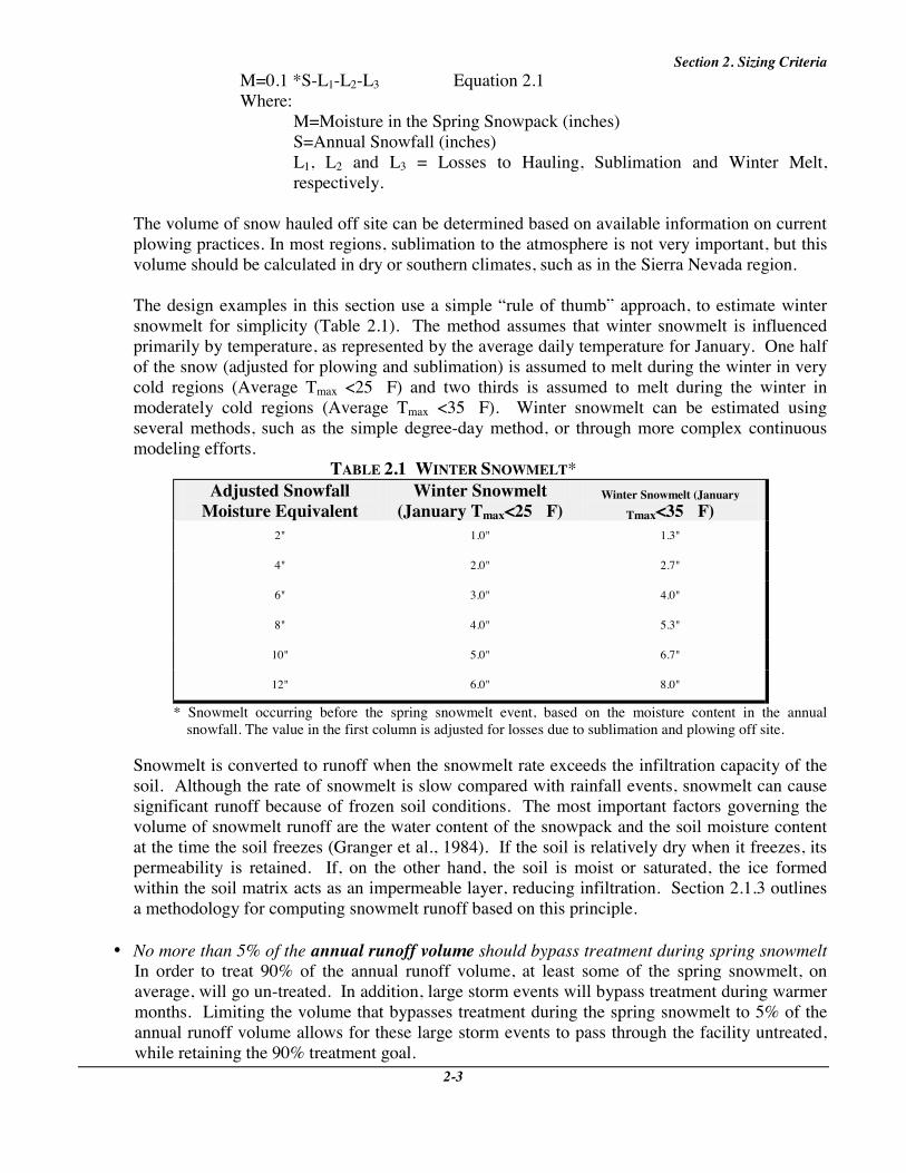
M=0.1 *S-L1-L2-L3 Equation 2.1 Where:
M=Moisture in the Spring Snowpack (inches) S=Annual Snowfall (inches) L1, L2 and L3 = Losses to Hauling, Sublimation and Winter Melt,
respectively.
The volume of snow hauled off site can be determined based on available information on current plowing practices. In most regions, sublimation to the atmosphere is not very important, but this volume should be calculated in dry or southern climates, such as in the Sierra Nevada region.
The design examples in this section use a simple “rule of thumb” approach, to estimate winter snowmelt for simplicity (Table 2.1). The method assumes that winter snowmelt is influenced primarily by temperature, as represented by the average daily temperature for January. One half of the snow (adjusted for plowing and sublimation) is assumed to melt during the winter in very cold regions (Average Tmax <25 F) and two thirds is assumed to melt during the winter in moderately cold regions (Average Tmax <35 F). Winter snowmelt can be estimated using several methods, such as the simple degree-day method, or through more complex continuous modeling efforts.
TABLE 2.1 WINTER SNOWMELT* Adjusted Snowfall
Moisture Equivalent Winter Snowmelt
(January Tmax<25 F) Winter Snowmelt (January
Tmax<35 F) 2" 1.0" 1.3"
4" 2.0" 2.7"
6" 3.0" 4.0"
8" 4.0" 5.3"
10" 5.0" 6.7"
12" 6.0" 8.0"
* Snowmelt occurring before the spring snowmelt event, based on the moisture content in the annual snowfall. The value in the first column is adjusted for losses due to sublimation and plowing off site.
Snowmelt is converted to runoff when the snowmelt rate exceeds the infiltration capacity of the soil. Although the rate of snowmelt is slow compared with rainfall events, snowmelt can cause significant runoff because of frozen soil conditions. The most important factors governing the volume of snowmelt runoff are the water content of the snowpack and the soil moisture content at the time the soil freezes (Granger et al., 1984). If the soil is relatively dry when it freezes, its permeability is retained. If, on the other hand, the soil is moist or saturated, the ice formed within the soil matrix acts as an impermeable layer, reducing infiltration. Section 2.1.3 outlines a methodology for computing snowmelt runoff based on this principle.
• No more than 5% of the annual runoff volume should bypass treatment during spring snowmelt In order to treat 90% of the annual runoff volume, at least some of the spring snowmelt, on average, will go un-treated. In addition, large storm events will bypass treatment during warmer months. Limiting the volume that bypasses treatment during the spring snowmelt to 5% of the annual runoff volume allows for these large storm events to pass through the facility untreated, while retaining the 90% treatment goal.

BMP Design Supplements for Cold Climates
The resulting equation is: T=(Rs-0.05R)A/12 (Equation 2.2) Where: T = Volume Treated (acre-feet) Rs = Snowmelt Runoff [See Section 2.1.3] R = Annual Runoff Volume (inches) [See Section 2.1.2] A = Area (acres)
• BMPs can treat a volume greater than their normal size. Snowmelt occurs over a long period of time, compared to storm events. Thus, the BMP does not have to treat the entire water quality treatment volume computed over twenty four hours, but over a week or more. As a result, the necessary water quality volume in the structure will be lower than the treatment volume. For this manual, we have assumed a volume of ½ of the value of the computed treatment volume (T) calculated in equation 2.2.
Thus, WQv = ½ T (Equation 2.3) 2.1.2 Base Criteria/ Annual Runoff The base criterion is the widely-used, traditional water quality sizing rule. This criterion, originally developed for moderate climates, represents the minimum recommended water quality treatment volume. In this manual, the runoff from a one inch rainfall event is used as the base criteria. The basis behind this sizing criteria is that approximately 90% of the storms are treated using this event. This value may vary nationwide, depending on local historical rainfall frequency distribution data. However, the one inch storm is used as a simplifying assumption. The base criteria included in this manual is chosen because it incorporates impervious area in the sizing of urban BMPs, and modifications are used nationwide. The cold climate sizing modifications used in this manual may be applied to any base criteria, however. Runoff for rain events can be determined based on the Simple Method (Schueler, 1987). r = p(.05+.9I) (Equation 2.4) Where: r = Event Rainfall Runoff (inches) p = Event Precipitation (inches) I = Impervious Area Fraction Thus, the water quality volume for the base criteria can be determined by: WQv = (0.05+.9I) A/12 (Equation 2.5) Where: WQv = Water Quality Volume (acre-feet) I = Impervious Fraction A = Area (acres) The Simple Method can also be used to determine the annual runoff volume. An additional factor, Pj, is added because some storms do not cause runoff. Assume Pj = 0.9 (Schueler, 1987). Therefore, annual runoff volume from rain can be determined by: R = 0.9 P (0.05+.9I) (Equation 2.6) Where: R = Annual Runoff (inches) P = Annual Rainfall (inches)

Section 2. Sizing Criteria
2-5
2.1.3 Calculating the Snowmelt Runoff To complete water quality sizing, it is necessary to calculate the snowmelt runoff. Several methods are available, including complex modeling measures. For the water quality volume, however, simpler sizing methods can be used since the total water quality volume, not peak flow, is critical. One method, modified from Granger et al. (1984) is proposed here. Other methods can be used, particularly those adjusted to local conditions. According to Granger et al. (1984) the infiltration into pervious soils is primarily based on the saturation of the soils prior to freezing. While saturated soils allow relatively little snowmelt to infiltrate, dry soils have a high capacity for infiltration. Thus, infiltration volumes vary between wet, moderate and dry soil conditions (Figure 2.2).
FIGURE 2.2 SNOWMELT INFILTRATION BASED ON SOIL MOISTURE
Assume also that impervious area produces 100% runoff. The actual percent of snowmelt converted to runoff from impervious areas such as roads and sidewalks may be less than 100% due to snow removal, deposition storage and sublimation. However, stockpiled areas adjacent to paved surfaces often exhibit increased runoff rates because of the high moisture content in the stockpiled snow (Buttle and Xu, 1988). This increased contribution from pervious areas off-sets the reduced runoff rates from cleared roads and sidewalks.

BMP Design Supplements for Cold Climates
The resulting equation to calculate snowmelt runoff volume based on these assumptions is: RS = [runoff generated from the pervious areas] + [runoff from the impervious areas] Rs = [( 1 - I )( M-Inf )] + [( I )( 1 )( M )] (Equation 2.7) where: RS = Snowmelt Runoff I = Impervious Fraction M = Snowmelt (inches) Inf = Infiltration (inches) Sizing Example 1: Snowpack Treatment Scenario: 50 Acre Watershed
40% Impervious Area Average Annual Snowfall= 5'=60" Average Daily Maximum January Temperature = 20 Average Annual Precipitation = 30" 20% of snowfall is hauled off site Sublimation is not significant Prewinter soil conditions: moderate moisture.
Step 1: Step 2:
Determine if oversizing is necessary Since the average annual precipitaiton is only ½ of average annual snowfall depth, oversizing is needed. Determine the annual losses from sublimation and snow plowing. Since snow hauled off site is about 20% of annual snowfall, the loss from snow hauling, L1, can be estimated by: L1 = (0.2)(0.1)S Where: L1 = Water equivalent lost to hauling snow off site (inches) S = Annual snowfall (inches) 0.1 = Factor to convert snowfall to water equivalent Therefore, the loss to snow hauling is equal to: L1 = (0.2)(0.1)(60") L1 = 1.2" Since sublimation is negligible, L2 = 0
Step 3: Determine the annual water equivalent loss from winter snowmelt events Using the information in Step 2, the moisture equivalent in the snowpack remaining after hauling is equal to: 60" 0.1-1.2" = 4.8" Substituting this value into Table 2.1, and interpolating, find the volume lost to winter melt, L3. L3 = 2.4"

Section 2. Sizing Criteria
2-7
Step 4: Calculate the final snowpack water equivalent, M M = 0.1 S-L1-L2-L3 (Equation 2.1) S = 60" L1 = 1.2" L1 = 0" L3 = 2.4" Therefore, M = 2.4"
Step 5: Calculate the snowmelt runoff volume, Rs Rs = (1-I)(M-Inf)+ I M Equation 2.7 M =2.4" I =0.4 Inf =0.8" (From figure 2.2; assume average moisture) Therefore, RS = 1.9"
Step 6: Determine the annual runoff volume, R Use the Simple Method to calculate rainfall runoff: R=0.9(0.05+0.9*I)P (Equation 2.6) I=0.4 P=30" Therefore, R=11"
Step 7: Determine the runoff to be treated Treatment, T should equal: T= (Rs-0.05*R) A/12 (Equation 2.2) Rs=1.9" R =11" A = 50 Acres Therefore, T=5.6 acre-feet
Step 8: Size the BMP The volume treated by the base criteria would be: WQv=(.05+.9*.4)(1'/12")(50 acres) = 1.7 acre-feet (Equation 2.5) For cold climates: WQv=1/2(T) = 2.8 acre-feet (Equation 2.3) The cold climate sizing criteria is larger, and should be used to size the BMP.
2.1.4 Rain-on-Snow Events For water quality volume, an analysis of rain-on-snow events is important in coastal regions. In non-coastal regions, rain-on-snow events may occur annually but are not statistically of sufficient volume to affect water quality sizing, especially after snowpack size is considered. In coastal regions, on the other hand, flooding and annual snowmelt are often driven by rain-on-snow events (Zuzel et al., 1983). Nearly 100% of the rain from rain-on-snow events and rain immediately following the spring melt is converted to runoff (Bengtsson, 1990). Although the small rainfall events typically used for BMP water quality do not produce a significant amount of snowmelt (ACOE, 1956), runoff produced by these events is high because of frozen and saturated ground under snow cover. Many water quality volume sizing rules are based on treating a certain frequency rainfall event, such as treating the 1-year, 24-hour rainfall event. The rationale of treating 90% of the pollutant load (Schueler, 1992) can also be applied to rain-on-snow events, as shown in the following example.
BMP Design Supplements for Cold Climates
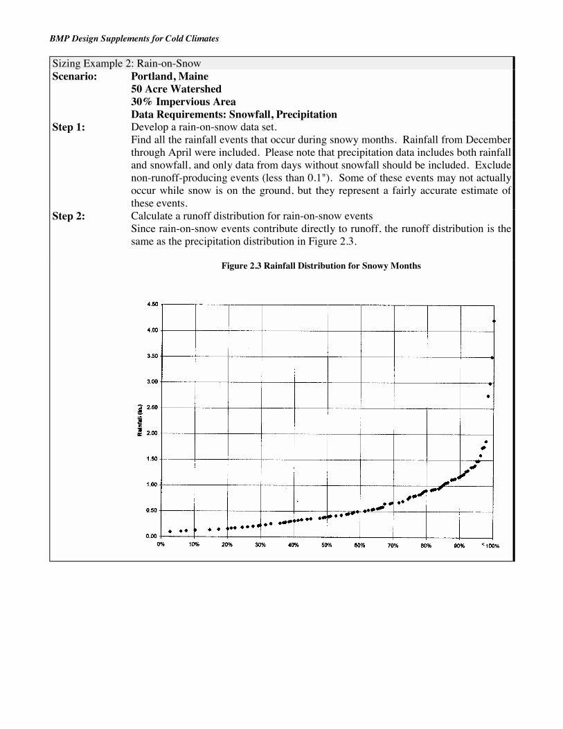
Sizing Example 2: Rain-on-Snow Scenario: Portland, Maine
50 Acre Watershed 30% Impervious Area Data Requirements: Snowfall, Precipitation
Step 1: Develop a rain-on-snow data set. Find all the rainfall events that occur during snowy months. Rainfall from December through April were included. Please note that precipitation data includes both rainfall and snowfall, and only data from days without snowfall should be included. Exclude non-runoff-producing events (less than 0.1"). Some of these events may not actually occur while snow is on the ground, but they represent a fairly accurate estimate of these events.
Step 2: Calculate a runoff distribution for rain-on-snow events Since rain-on-snow events contribute directly to runoff, the runoff distribution is the same as the precipitation distribution in Figure 2.3.
Figure 2.3 Rainfall Distribution for Snowy Months

Section 2. Sizing Criteria
2-9
Step 3: Calculate a rainfall distribution for non-snow months. Develop a distribution of rainfall for months where snow is not normally on the ground. The rainfall distribution for May through November is included in Figure 2.4.
Figure 2.4 Rainfall Distribution for Non-Snowy Months
Step 4: Calculate the runoff distribution for non-snow months.
Use a standard method to convert rainfall to runoff, particularly methods that are calibrated to local conditions. For this example, use the Simple Method. Runoff is calculated as: r=(0.05+0.9 I)p (Equation 2.4) For this example, I=0.3 (30% impervious area), so: r=0.32 p The runoff distribution for non-snow months is calculated by multiplying the rainfall in Figure 2.4 by 0.32.
Step 5: Combine the runoff distributions calculated in Steps 2 and 4 to produce an annual runoff distribution. The resulting runoff distribution (Figure 2.5) will be used to calculate the water quality volume.

BMP Design Supplements for Cold Climates
Figure 2.5 Annual Runoff Distribution: Portland, Maine
Step 6: Size the BMP.
In this case, use the 90% frequency runoff event (Figure 2.4), or 0.65 watershed inches. This value is greater than the base criteria of 0.32 watershed inches (1" storm runoff). Therefore, the greater value is used. WQv=(0.65 inches) (1 foot/12 inches) (50 acres) = 2.7 acre-feet
2.2 Water Quantity Sizing Some BMPs, particularly detention basins, are used to prevent downstream flooding and channel erosion. Three different events are controlled: a channel protection storm (usually 2-year), an overbank protection event (5-10 year storm) and an extreme flood event (50-100 year). While different sizing criteria are developed for water quality because of the high loading associated with the snowmelt event, the only changes in water quantity sizing are to adjust the inflow hydrology to cold weather conditions (Figure 2.6).
Of the three events controlled for water quantity, the extreme flood event is the only one for which rain-on-snow and snowmelt events typically need to be considered. The two goals in controlling this storm are to reduce peak flows to pre-development conditions and pass the flood event safely. Since rain-on-snow and snowmelt peak flows can be extremely large, these events should be considered primarily to ensure that the stormwater management facility does not fail under the design snowmelt or rain-on-snow events.

Section 2. Sizing Criteria
2-11
FIGURE 2.6 WATER QUANTITY SIZING CRITERIA
Snowmelt and rain-on-snow events rarely need to be considered when designing for channel protection or overbank protection. The only objective in controlling the channel protection and overbank protection events is to reduce the peak flow from a runoff event to pre-development levels. Although snowmelt and rain-on-snow events can produce high runoff volumes, the difference between pre-development and post-development flows is more pronounced for warm season rainfall events. Since the ground is often frozen or saturated during the spring snowmelt period, the flows produced in pre-development storms are very high. There are some cases where rain-on-snow events should be used to size BMPs for channel protection. If the downstream channel has highly erosive soils, extra channel protection may be needed for the snowmelt event. This event, although it has low peak flows compared to rainfall, is sustained for a long period of time. Thus, the critical velocity for erosion may be exceeded with snowmelt events for these soils. An additional note for this section is that the calculations presented to size BMPs for water quantity are only examples. A more comprehensive summary of snow flooding calculations, the Snow Hydrology Guide was compiled by the Ontario Ministry of Natural Resources (OMNR, 1989). In addition, several commercial models are available to compute runoff from snowmelt and rainfall events. 2.2.1 Sizing for Rainfall Events Most jurisdictions have flood and channel protection requirements based on rainfall events, such as the 2-year, 10-year and 100-year rainfall. One goal of controlling these storms is to reduce peak flows to “pre-development” levels. In addition, any dams must include an emergency spillway that can safely attenuate or otherwise control flows in excess of the extreme flood (usually 50- or 100-year storm). Regardless of climate, the storm-based criteria need to be met.

BMP Design Supplements for Cold Climates
2.2.2 Sizing for the Spring Snowmelt Event While the spring snowmelt event does not produce the “flashy” response typically associated with rainfall-driven flood events, the volume of runoff produced can cause flooding over time. One substantial difference between snowmelt and streamflow hydrographs is that a major portion of the streamflow is from groundwater discharge associated with the spring melt. In the summer, these flows are much lower. In addition, there are some models specifically developed to analyze snowmelt runoff (Kutchment, 1996, for example). A simple five step approach to sizing BMPs for water quantity is presented below. The steps are tasks that generally need to be completed to design for the snowmelt event, regardless of the specific technique used. The modifications to hydrology are described in relation to the technique outlined in “Urban Hydrology for small Watershed” or TR-55 (USDA, 1986), but can be applied to almost any basic hydrologic method. Step 1: Determine the snowmelt rate
There are a variety of factors that influence snowmelt, ranging from solar intensity to the age of the snowpack. While a number of models are available to calculate snowmelt, many are either data intensive or require extensive calibration. A simple method of calculating snowmelt is to assume that the snowmelt is related only to the average or maximum air temperature, the Degree-Day method. Other methods can obtain more accurate data under some conditions, but generally require extensive data inputs (e.g., Kutchment, 1996). In the Degree-Day method, the melt can be calculated as:
M= (T-32) F where:
T= average daily temperature ( F) F= melt factor (inches/F )
While the melt factor can be vary, and should be estimated from local data where possible, Haith (1985) proposes a value of about 0.1"/F as a default value. The resulting equation would be:
M= 0.1 (T-32) Step 2: Adjust the surface runoff component
The spring snowmelt generally takes place over saturated or frozen ground. Some adjustment is needed to account for the relative impermeability of this surface.
Option 1: Use a “saturated curve number”
Hawkins (1978) proposed one method used to modify the curve number for saturated ground conditions. Using this saturated curve number, CNsat, is one adjustment for the period when
the ground is covered with snow. This option is recommended because it is supported by field data. The modified curve number is equal to: CN sat = CN
0.4036 + 0.0059 CN

Section 2. Sizing Criteria
2-13
Option 2: Increase impervious area
Another method is to increase the impervious area when determining the curve number. The degree to which impervious area increases is usually based on the professional judgement of the designer. One simple assumption is to double the impervious area when the ground is snow-covered. This assumption has limitations in evaluating the pre-development condition, where there is no impervious area
Option 3: Use a less permeable soil type Some stormwater practitioners suggested using a “C” or “D” soil type for winter runoff or snowmelt events to account for the effect of frozen ground. This method is consistent with the idea that snow cover and frozen ground act to reduce the infiltration capacity of the soil. One obvious disadvantage of this method is that it is not practical when the site has these soils in the non-frozen condition.
Step 3: Select a design event While rain storms are one-day events, design spring snowmelt events may occur over a few
weeks. Two options are presented below, depending on data availability. Option 1: Select a design flood year
If extensive streamflow records are available, it may be acceptable to pick a design year, based on historical flood records. Unfortunately, these data are often not available.
Option 2: Select design snowfall records
When streamflow records aren’t available, designers can use the design snowfall, e.g. the 100-year total snowfall with the temperature conditions from that year.
Step 4: Use a continuous model
Floods caused by snowmelt result from sustained but not “flashy” responses. While design storms for peak rainfall events can be determined based on individual events, this type of analysis is not as appropriate for snowmelt, especially in larger basins. Some continuous models that include snowmelt processes are:
• DR3M-QUAL: Distributed Routing Rainfall-Runoff Model (Alley and Smith, 1982) • WLF: Generalized Watershed Loading Functions (Haith et al., 1992) • HSPF: Hydrologic Simulation Program - FORTRAN (Bicknell et al., 1993) • SITEMAP: Stormwater Intercept and Treatment Evaluation Model for Analysis and Planning
(Omicron Associates, 1990) • SWMM: Stormwater Management Model (Huber, W.C. and R.E. Dickinson, 1991)
Alternatively, repetitive analysis with TR-55 may be appropriate for pond sizing. That is, the storage taken up in a pond is calculated based on a single application of TR-55. This analysis is used to set the initial storage available for the next day of snowmelt. Step 5: Size the BMP
Simple BMP sizing can be used, since the goal is only to reduce the peak daily flow. Sizing should be sufficient to reduce the peak daily flow to an acceptable level.
2.2.3 Sizing for Rain-on-Snow Events

BMP Design Supplements for Cold Climates
The goals for rain-on-snow events are exactly the same as for rain events: control peak flows to pre-development levels and allow extreme flood events to pass safely. Modifications to hydrologic calculations for rain-on-snow events follow below. Selecting a rain-on-snow event The same basic procedure as selecting a design rainfall event is followed. Only rainfall for the months where snow is on the ground is analyzed, resulting in recurrence frequencies for given rain-on-snow events. Adjust the curve number Use one of the methods discussed in Section 2.2.2, preferably the saturated curve number, to adjust the curve number for frozen, saturated conditions. Assume some flood storage is taken up Non-winter water quality sizing assumes that the BMP is empty at the time of the design event. In winter conditions, snowmelt may result in some storage being occupied. Assume that the water quality volume is full at the time of the event. Alternatively, use continuous modeling to route flows through the BMP.

3-1
3. Ponds Although ponds have reduced effectiveness in cold conditions, they are the most highly recommended BMPs in cold regions (CWP, 1997). The following section discusses methods to improve the performance of pond systems in cold climates. 3.1 Types of Ponds Three types of stormwater ponds are wet ponds, dry extended detention ponds, and wet extended detention ponds. These ponds differ in the volume of permanent pool versus extended detention used to treat stormwater runoff (Figure 3.1). Wet ponds rely entirely on the permanent pool to treat stormwater runoff. This treatment is accomplished through biological activity and settling while runoff resides in the system. The concept in this design is that incoming runoff displaces the permanent pool, and the treated water flows out of the system. Dry extended detention ponds treat runoff by detaining it for a given period of time (usually 24-hours). In these ponds, pollutant removal is accomplished through settling when runoff is detained. Wet extended detention ponds combine the concepts in wet ponds and dry extended detention ponds by dividing treatment between a permanent pool and extended detention. Part of the runoff is detained, and a remainder is treated in the permanent pool.
FIGURE 3.1 TYPES OF STORMWATER PONDS
3.2 Base Criteria The standard features of stormwater pond designs (CWP et al., 1997) are presented in Table 3.1. These standard features represent the base stormwater pond design criteria. The base criteria ensure that stormwater ponds effectively treat stormwater runoff and efficiently remove pollutants. In cold climates, the effectiveness of pond systems may be compromised by climatic conditions. This chapter discusses design modifications to compensate for cold climate impacts.

3-2
TABLE 3.1 FEATURES OF A STANDARD STORMWATER POND SYSTEM
Criteria Description Adequate Water Quality Treatment Volume
(See Section 2).
Multiple Treatment Pathways Provide longer flowpaths, high surface to volume ratio or different treatment methods (e.g., pool and marsh).
Pond Geometry Ponds should be wedge-shaped, narrowest at the inlet and widest at the outlet. Maximum depth should be 8', with an average depth of 4'-6'.
Pretreatment Each pond should have a sediment forebay, with maintenance access for cleaning.
Non-Clogging Low-Flow Orifice
Accomplish this with a trash rack or other protection mechanism.
Riser in the Embankment For convenience, safety, maintenance access and aesthetics.
Pond Drain Used to drain the pond for maintenance or emergencies.
Adjustable Gate Valve The pond drain and the extended detention pipe (if a pipe is used) should be equipped with an adjustable gate valve.
Principal Spillway Designed to safely pass the 5- to 10-year storm.
Emergency Spillway Designed to safely pass the 50- to 100- year storm.
Embankment Specifications Designed to prevent dam breach or seepage (NRCS dam safety criteria).
Inlet Protection Protect against erosion or scour at the inlet. Outfall Protection Use flared end pipe sections, and stabilize the downstream channel.
Prevent stream warming with an underdrain channel or by limiting tree-clearing.
Pond Benches Provide flat-sloped safety and aquatic benches at the pond edge for safety purposes and to promote wetland vegetation.
Pondscaping Plan The plan describes how the pond areas will be vegetated.
Wetland Elements Use of wetlands plants in pond systems is encouraged in shallow pond areas.
Buffers A vegetated buffer should be provided at least 25' outward from the edge of the pond.
Maintenance Measures Maintenance will include some mowing, annual inspection, periodic removal of sediment from the forebay, spillway structural measures as necessary and correction of erosion problems.
Maintenance Access A right-of-way should be provided for maintenance vehicles, and riser structures should be easily accessible through lockable manhole covers.

3-3
3.3 Cold Climate Modifications Many of the cold climate factors outlined in Chapter 1 can significantly impair the effectiveness of pond systems. Despite these challenges, ponds are considered the most functional and reliable of BMPs used in cold regions (with the exception of completely dry extended detention ponds). Pond systems can perform well in cold climates because many modification options are available to increase their effectiveness in frigid and snowy conditions. 3.3.1 Conveyance Inlets, outlet structures and outfall protection for pond systems require modifications to function well in cold climates. Most of these modifications address the problems associated with pipe freezing. Inlets Guidelines for protecting inlets under various scenarios are presented in Table 3.2. Two slightly different criteria are used for cold and extremely cold (based on January temperature) climates. In very cold climates, criteria are slightly stricter (e.g., larger diameter pipes) and there are fewer exceptions.
• Bury Below the Frost Line Burying pipes below the frost line can prevent frost heave and pipe freezing. Many communities require burial of storm sewer pipes, so at least a portion of the inlet pipe may be below the frost line due to existing rules. “Daylighting” the inlet pipe at the point where it enters the pond will require some of the pipe to be above the frost line (Figure 3.2). Burying the point furthest from the pond deeper than the frost line minimizes the length of pipe exposed to frost. It may not be possible to bury pipes below the frost line in areas of low relief because of the difficulty in achieving positive drainage. In addition, it may not be feasible to bury pipes below the frost line when the frost line is very deep (greater than 5') because of high excavation costs.
• Pipe Slope>1%
Increasing the slope of the inlet pipe prevents standing water in the pipe, reducing the potential for ice formation. It may be difficult to achieve this goal in low relief. When the slope of the pipe is nearly equal to the slope of the ground, it will be difficult to daylight the pipe.

Section 3. Ponds
3-4
TABLE 3.2 DESIGN GUIDELINES FOR POND INLETS
Criteria January Temperature 25 - 35 January Temperature <25 Bury below frost line Use except in areas of low relief Use except in areas of low relief or
when the frost line >5' Slope >1% Use except in areas of low relief Use except in areas of low relief Minimum diameter 15" minimum diameter;
18" for low relief areas 18" minimum diameter;
21" for low relief Overexcavate and backfill with gravel or sand
Surround pipe with >6" of gravel or sand
Surround pipe with >9" of gravel or sand
Avoid submerged inlet pipes1
Avoid in most cases Always Avoid
Insulation Not necessary Not required when the growing season > 120 days
Use on-line treatment Encouraged where possible Encouraged where possible 1 applies only to wet and wet extended detention ponds
FIGURE 3.2 DAYLIGHTING INLET PIPES
• Minimum Pipe Diameter By increasing the pipe diameter, ice is less likely to block the pipe. Larger diameter pipes have a larger area for flow to pass if some ice formation has occurred, and a lower exposed pipe to volume ratio, limiting freezing potential. In areas of low relief, the pipe diameter should be increased more to compensate for inability to bury pipes or achieve steep slopes.

Section 3. Ponds
3-5
• Overexcavate and Backfill with Gravel or Sand (Figure 3.3)
Overexcavating for pipes and backfilling with gravel or sand protects against frost heaving. This coarser-grained material is less susceptible to frost heave. This process increases construction costs because of the cost of hauling in sand or gravel, extra excavation and disposing of extra soil.
FIGURE 3.3 OVEREXCAVATION AND BACKFILL WITH GRAVEL/SAND
• Avoid Submerged Inlet Pipes (Figure 3.4) Submerged or partially submerged inlet pipes should be avoided in cold climates when possible. The permanent water storage in submerged pipes can freeze, creating upstream flooding. One disadvantage to unsubmerged pipes is that the runoff has more energy when it hits the pond surface. Riprap or other erosion control is needed to prevent erosion as a result of the increased runoff velocity.
• Use Insulation Surrounding pipes with insulation is expensive, and is generally only needed in very cold climates (e.g., Anchorage DPW, 1988). Insulation protects pipes from freezing and frost heave by creating a temperature barrier between pipes and frozen ground.
• On-Line Treatment On-line ponds receive flows from all storms, as well as baseflow events. By continuously moving baseflow through a pond system, the constant baseflow will discourage ice build-up, especially at outlets. This method is particularly effective when combined with the outlet structure modifications described below, and in Appendix B. There are some caveats to the use of on-line designs, however. The use of on-line ponds is often not practical due to wetlands regulations. In addition, there is some concern that the use of on-line ponds can cause downstream degradation. These issues need to be addressed before an on-line system is used.

Section 3. Ponds
3-6
FIGURE 3.4 SUBMERGED INLET PIPES
Outlet Structures Four basic outlet structures are discussed in this section: perforated riser pipes, riser pipes, concrete riser boxes and weirs (Table 3.3). Each outlet structure serves the same purpose: containing runoff in the pond for treatment or flood reduction.
TABLE 3.3 DESIGN GUIDELINES FOR POND OUTLET STRUCTURES
Outlet Type
Perforated Riser Pipe
Riser Pipe
Concrete Riser Box
Weir Structure
Schematic Application(s)
Wet ED Dry ED
Wet Ponds
Wet Pond Dry ED Wet ED
Wet Pond Dry ED Wet ED
Climates
Limited use in cold climates
January Tmax>25 F
January Tmax>25 F or growing season>120 days
All cold climate
Modifications
Minimum 6" diameter Minimum ½" perforation diameter
Riser in the embankment Minimum 18" diameter.
Riser base below the frost line Low flow pipe diameter 6" Riser in the embankment
Weir base below the frost line Minimum weir slot width of 3” Alternate weir structures

Section 3. Ponds
3-7
• Perforated Riser Pipe These structures are used to control detention for water quality only. Flood storage is provided by a separate orifice. Holes, or perforations, in the pipe control the rate at which water leaves the pond above the permanent pool. They are often used in dry detention facilities as a low flow orifice. This low cost option is often attractive, especially for retrofits. It should be used with caution in cold climates, however, because ice cover can cause clogging of the orifices. If perforated riser pipes are used in cold climates, the minimum orifice diameter should be ½". In addition, the pipe should have a minimum 6" diameter.
• Riser Pipe
Riser pipe structures consist of a pipe that is open on the top, and covered with some sort of hood or trash rack device. Riser pipe outlets do not provide any extended detention, but are used to maintain the permanent pool in wet pond designs. Some modifications are necessary to use these systems in cold climates, especially if a thick ice layer is present.
A minimum 18" diameter is required. In addition, the riser pipe should be placed within the embankment. Both requirements prevent freezing in the riser pipe.
• Concrete Riser Concrete risers are box-like structures at the outlet of pond systems. In these structures, pipes extending from the riser or slots in the concrete itself control flow. These structures can control both low-flow and high-flow events. They are generally effective in cold climates, although there may be problems with freezing if pipes are used to control flow.
Low flow outlet pipes from concrete risers need to have a six inch minimum diameter to prevent freezing. In addition, concrete risers should be placed in the embankment to prevent frost heave and to protect pipes within the riser from freezing.
• Weir Structure
Weir structures can control all flow events, by using various weir widths. These structures are attractive in cold climates because of their “non-icing” nature.
When a standard weir is used, the minimum slot width should be 3", especially when the slot is tall. The disadvantage to this approach is that the desired retention time may be difficult to achieve. Other weir design alternatives are available, such as the proportional weir (Figure 3.5). In this design, the weir is wider at the bottom and decreases in width near the top. It is easier to achieve slower release rates with this design.
• Alternative outfall designs are described in Appendix B. The designs focused on in that section
are resistant to icing and clogging in cold conditions.

Section 3. Ponds
3-8
FIGURE 3.5 PROPORTIONAL WEIR
(SOURCE: MWCOG, 1996)
Outlet Pipes The outlet pipe, the pipe that conveys runoff from the outlet structure to the outfall, needs modifications to be effective in cold climates. Four modifications: adjusting minimum piping diameter, adjusting minimum pipe slope, burying pipes below the frost line and splash prevention are recommended for cold climates. The objective of these modifications is to prevent ice build-up within the outlet and avert potential flooding conditions.
• Minimum Diameter Outlet pipes should have at least an 18" diameter in all cold climates. Larger diameter pipes are less prone to freezing and ice build-up.
• Minimum Slope
The minimum slope recommended for outfall pipes is 1%. This slope maintains flow velocities to prevent standing water that can freeze and block the outlet pipe.
• Bury Below the Frost Line
To the extent practical, the outlet pipe should be buried below the frost line. Of course, some of the pipe will be exposed at the outfall, but this distance should be minimized.
• Splash Protection
One mechanism that causes ice build-up in outlets is splashing that occurs within the outlet pipe. Over a cold season, ice builds up as a result of this splashing. Simple precautions can reduce this risk somewhat. First, drop-offs at the beginning and end of the outlet pipe should be avoided, because these areas can cause splashing. Second, designs should not include constrictions immediately downstream. This conditions can cause turbulence in the pipe, which results in splashing. Finally, pipes should not be designed with sharp slope changes, as these changes in slope can result in splashing or turbulence.

Section 3. Ponds
3-9
Outfall Protection In cold climates, two modifications are needed to ensure adequate outfall protection. First, the outfall channel should be stabilized as soon as possible following construction of the pond. Second, if an underdrain is used to prevent downstream warming, it should be encased in gravel and have at least an 8" diameter.
• Rapid Channel Stabilization In areas with a short growing season (<120 days), stabilizing the channel of the pond outfall is a challenge. Two options can prevent this problem. Fast-growing plant species can be used, but only if planted at the beginning of the growing season. Alternatively, structural measures such as rip rap or geotextile materials can be used to stabilize the channel.
• Stream-Warming Protection During the summer, pond discharge may significantly increase in temperature as it flows through heated riprap channels at pond outlets (Galli, 1990). One solution to this problem is to route base flows through an underdrain pipe below the riprap outlet (Figure 3.6). In cold climates, protections should be made against frost heaving, such as encasing the underdrain pipe in gravel.
FIGURE 3.6 UNDERDRAIN SYSTEM

Section 3. Ponds
3-10
3.3.2 Pretreatment All pond systems should be equipped with a forebay system. Two modifications can make the forebay more effective in cold regions. One modification is to increase the minimum size of the forebay from 0.1" to 0.25" per impervious acre. In cold climates, the capacity of the forebay system is reduced, due to icing, and this additional storage is necessary to provide pretreatment during the cold season. The use of a weir system can provide some settling above a frozen forebay (Figure 3.7). This option slows incoming runoff, providing some settling in the forebay. When the pond is iced over, runoff can “skate” over the pond system, bypassing treatment. By slowing the runoff, this problem is mitigated somewhat.
FIGURE 3.7 FOREBAY WITH A WEIR SYSTEM

Section 3. Ponds
3-11
3.3.3 Treatment Cold climate treatment modifications focus on three aspects of pond design: treatment volume, chloride treatment and geometry (Table 3.4).
TABLE 3.4 TREATMENT MODIFICATIONS FOR PONDS IN COLD CLIMATES Modification Application Restrictions/ Drawbacks
Treatment Volume
25% Minimum ED Storage
Needed for January Tmax <=25 F Applicable in all cold climates
• Wet ponds preferred in residential settings if the depth of detention is greater than 2'.
Seasonal Operation Applicable in all Cold Climates Substitute for 25% ED storage
• Sometimes conflicts with wetlands preservation
• Requires physical manipulation of pond levels
Add storage to compensate for ice build-up
Needed where ice depth exceeds 6"
• Adds to the cost of pond construction
Use Circulation or Aeration to Prevent Ice Build-up
Applicable when Tmax <=25 F • Expensive • Safety Hazard
Geometry Ponds deepest at outlet
Needed in all cold climates • Some safety concerns
Use Multiple Ponds Encouraged in all cold climates • Adds to the cost of pond construction
• Not always feasible • Inlets between ponds may freeze.
Treatment Volume In cold climates, the treatment volume of a pond system should be adjusted to account for ice build-up on the permanent pool. Three adjustment options are presented below. These adjustments should be made after determining the water quality treatment volume (Section 2, Sizing Criteria).
• Use a Minimum of 25% Extended Detention Storage (Figure 3.8) This recommendation is made for very cold climates to provide detention while the permanent pond is iced over. In effect, it discourages the use of wet ponds, replacing them with wet extended detention ponds.
• Seasonal Operation (Figure 3.9) In this option, proposed by Oberts (1994), the pond has two water quality outlets, both equipped with gate valves. In the summer, the lower outlet is closed. During the fall and throughout the winter, the lower outlet is opened to draw down the permanent pool. As the spring melt begins, the lower outlet is closed to provide detention for the melt event. This method can act as a substitute to using a minimum extended detention storage volume.

Section 3. Ponds
3-12
When wetlands preservation is a downstream objective, seasonal manipulation of pond levels may not be desired. An analysis of the effects on downstream hydrology should be conducted before considering this option. In addition, the manipulation of this system requires some labor and vigilance; a careful maintenance agreement should be confirmed. Finally, gate valves can be substituted with simpler mechanisms, such as weir plates (Figure 3.10), if freezing is anticipated.
FIGURE 3.8 MINIMUM 25% EXTENDED DETENTION
FIGURE 3.9 SEASONAL POND OPERATION (SOURCE: OBERTS, 1994)

Section 3. Ponds
3-13
FIGURE 3.10 WEIR PLATE
• Additional Storage to Compensate for Ice Build-Up This recommendation is commonly made in cold climate areas. For example, Maine DEP (1995) suggests adding one foot of storage to compensate for the build-up of ice on the surface. This storage should not be added simply by digging the pond deeper, because factors other than the water quality volume influence the performance of stormwater BMPs (Schueler, 1993). The additional storage should be provided by increasing the surface area of the pond (Figure 3.11), maintaining a recommend maximum depth of eight feet (CWP et al., 1997). Providing additional storage to compensate for storage loss due to ice build-up is important, but it is not the only option to improve pond performance. Modifications such as non-icing outlets and pond geometry designed for cold climates also need to be taken into consideration.
• Circulation/Aeration Using pumps or bubbling systems can reduce ice build-up and prevent the formation of an anaerobic zone in pond bottoms. These systems are rarely used, however (CWP, 1997) because they can create a safety hazard due to thin ice and are an expensive option.
Geometry Ponds should be deepest at the outlet to prevent scouring as water flows out from under the ice at the exit of the pond (Oberts, 1994). One concern associated with this design is that having a deep zone near the edge of the pond may be a safety hazard. This concern can be alleviated by taking other precautions such as planting thick shrubs, including signs and using flat slope, or "benches" near the outlet. Multiple pond systems are recommended regardless of climate because they provide redundant treatment options. In cold climates they prevent flows from bypassing the pond system by “skating” over the ice. The barrier between multiple ponds increases the internal flowpath. In cold climates, a berm or simple weir should be used instead of pipes to separate multiple ponds. These pipes have a high potential to freeze.

Section 3. Ponds
3-14
FIGURE 3.11 STORAGE TO COMPENSATE FOR ICE BUILD-UP
3.3.4 Maintenance The maintenance of a pond system includes both design elements such as non-clogging outlets and routine maintenance procedures to keep the pond functional. These elements need to be modified slightly to adjust to cold climate conditions. Non-Clogging Outlets (Skimmers and Trash Racks) Non-clogging outlets are essential in a pond system. In cold climates, clogging can occur due to ice formation as well as trash build-up. Four non-clogging outlet design options are baffle weirs, hoods, trash racks and reverse-slope pipes Note: All of these mechanisms work best when used with an on-line pond (Section 3.3.1)

Section 3. Ponds
3-15
TABLE 3.5 MODIFICATIONS TO SKIMMERS AND TRASH RACKS
Practice Climate Outlet Type Modifications Baffle weirs All Cold Climates Concrete Riser
Weir Outlet None
Hood All Cold Climates Riser Pipe Concrete Riser
Weir Outlet
Draw from 6" below normal ice layer
Trash Rack All Cold Climates Higher flow spillways (Not water
quality)
Shallow Slope
Reverse-Slope Pipe Only with an on-line pond
Concrete Riser Minimum 6" diameter. Draw from 6" below normal ice
layer
• Baffle Weirs Baffle weirs are essentially fences in the pond that prevent trash from reaching the outlet structure. They are also recommended in cold climates because they prevent ice formation near the outlet by preventing surface ice from blocking the inlet (Figure 3.12), encouraging the movement of baseflow through the system.
FIGURE 3.12 BAFFLE WEIR (SOURCE: MODIFIED FROM MPCA, 1989)

Section 3. Ponds
3-16
• Hood In cold climates, riser hoods should draw from at least 6" below the typical ice layer. This design encourages circulation in the pond, preventing stratification and formation of ice at the outlet (Figure 3.13).
FIGURE 3.13 RISER HOOD
• Trash Rack Trash racks prevent large debris from flowing out of the pond system or clogging outlets. In cold climates, trash racks can become ice-covered. One possible modification is to install the trash rack at a shallow angle. In this design, ice formation does not cover the grate of the inlet as quickly (Figure 3.14).
• Reverse-Slope Pipe In this outlet design, a low-flow pipe extends from the riser through the embankment, drawing from below the permanent pool. In on-line systems, the pipe is prevented from freezing by the constant flow of baseflow through the pipe. Reverse slope pipes should be used sparingly in cold climates, and only in combination with an on-line pond. When reverse slope pipes are used, they should have a minimum diameter of 6" and should draw from 6" below the normal ice layer.

Section 3. Ponds
3-17
FIGURE 3.14 ALTERNATE TRASH RACK DESIGN
Routine Maintenance Routine maintenance is similar in cold and moderate climates. In cold climates, some additional maintenance may be needed for ice removal, ponds should not be drained during the spring season and extra sand removal may be required.
• Ice Removal In extremely cold climates (Tmax for January <25 F and growing season<120 days) , a “heat tracing” (electric) or steam ice removal system may be used to prevent ice build-up. In other cold regions, these measures should not be necessary.
• Pond Draining Ponds should not be drained during the spring season. Due to temperature stratification and high chloride concentrations at the bottom, the water may become highly acidic and anoxic. Draining water from the pond bottom may cause negative downstream effects.
• Sand Removal Most of sand applied to streets in snowy regions washes off during the spring snowmelt and subsequent storm events unless street sweeping is used. This additional sand can become a maintenance problem to pond systems. In areas where road sand is used, the forebay should be inspected each spring to determine if dredging is necessary. In general, dredging is needed if one half of the capacity of the forebay is full.

Section 3. Ponds
3-18
3.3.5 Landscaping In both cold and moderate climates, ponds should be landscaped with wetland materials in shallow areas where possible, and the area surrounding the pond should be vegetated. Guidelines on plant selection for and planting techniques for cold climates are included in Section 4.3.5, Table 4.5. 3.3.6 Snow Management Dry extended detention ponds can be used to store plowed snow throughout the season. Other pond systems should not be used for this purpose, as the permanent pool makes this practice impractical. Also, the concentrated pollutants in the snowpack may damage vegetation in pond systems.

4-1
4. Wetlands Stormwater wetlands are very similar to stormwater ponds, except that they are generally shallow and more extensively incorporate wetland vegetation into the design. The wetland plants remove pollutants by slowing runoff and through pollutant uptake. Extra design features need to be added to make wetland systems function. For example, shallow zones are needed in a wetland system to allow emergent wetland plants to grow. In cold climates, some modifications are needed to ensure the survival of these plants. 4.1 Types of Stormwater Wetlands Three different types of wetlands are described in this chapter: shallow marshes, pond/wetland systems, and extended detention wetlands (Figure 4.1). The difference between the three types of wetlands is the area and storage allocated to the high marsh (<6" depth), low marsh (6" to 18" depth), extended detention and deep water zones (Table 4.1).
FIGURE 4.1 TYPES OF STORMWATER WETLANDS (SOURCE: MODIFIED FROM SCHUELER, 1992)
In shallow marshes, most of the storage is in the high and low marsh areas, with the only deep water sections being the forebay and the micropool. This wetland type provides significant habitat value, but is the most space consumptive of the wetland treatment options. The pond/wetland system has the most deep water of the stormwater wetland options: the deep pool is usually about half of the treatment volume. This option has less habitat value than the marsh option, but is effective because of the multiple treatment mechanisms (pond and wetland). It also saves space compared to the shallow marsh.

BMP Design Supplement for Cold Climates
The extended detention wetland is the only option that provides extended detention in addition to settling and biological treatment. The extended detention zone must tolerate saturation, frequent inundation and fluctuating water levels.
TABLE 4.1 TREATMENT ALLOCATION FOR THREE MARSH TYPES
(SOURCE: SCHUELER, 1992) Shallow Marsh Pond/Wetland ED Wetland Treatment volume (Pool/Marsh/ED)
40%/60%/0% 70%/30%/0% 20%/30%/50%
Surface Area (Deep/Low Marsh/High Marsh)
20%/40%/40% 45%/25%/30% 20%/35%/45%
4.2 Base Criteria Schueler (1992) outlines base design criteria for stormwater wetlands. These criteria, presented in Table 4.2, apply in both cold and moderate climates.
TABLE 4.2 FEATURES OF A STANDARD STORMWATER WETLAND
• Minimum wetland/watershed area of 0.01 (0.02 for shallow marsh)
• Minimum drainage area of 25 acres (10 acres for ED wetland)
• Minimum Length to width ratio of 1:1
• Maintenance to remove built up sediment
• Use of a forebay and micropool (forebay not required in the pond/wetland system)
• Non-clogging outlet
• Use of mulch, transplant or volunteer vegetation to propagate wetland plants
• Maintenance/ landscaping agreement.
• Wetland buffer between 25 and 50 feet.
• Use of high marsh wedges to increase the flow path
• Use of multiple cells within the wetland system
4.3 Cold Climate Modifications Many of the cold climate modifications for wetlands are very similar to the modifications for ponds (Section 3). The reader is referred to Section 3 (Ponds) for some of these modifications. Modifications in this section relate to treatment allocation, based on depth zones, and wetland plant species choices. 4.3.1 Conveyance The cold climate modifications to conveyance structures for wetlands are the same as the modifications to ponds. Refer to Section 3.3.1 for criteria on protecting inlet and outlet structures from cold climate challenges.

Section 4. Wetlands
4-3
4.3.2 Pretreatment First, the forebay, where used, should be increased to 0.25" per impervious acre. Second, a weir system to separate the forebay from the wetland further enhances the performance of the forebay. As in pond systems, the forebay prevents runoff “skating” over the top of the wetland system when frozen. An additional benefit of a forebay in wetland systems is that it can help dilute the chlorides in runoff, protecting wetland plants. 4.3.3 Treatment The treatment modification options presented in this section are developed in response to ice build-up on the surface of wetland systems. These options, along with the regions where they apply and some of their drawbacks (see Table 4.3) are included in this section. Because wetlands are shallow systems, ice can take up almost all of the treatment volume during the winter season. The treatment modification options also address the concern of chlorides entering the wetland system, changing species composition.
Minimum Extended Detention Storage A minimum extended detention storage of 25% is recommended for cold climates, replacing some of the wet storage in wetlands with dry extended detention. The goal is to provide some treatment throughout the winter, when much of the permanent pool and marsh storage may be frozen. The same recommendation was made for pond systems. At least 50% of storage in deep pool This treatment option basically uses the pond/wetland system design option. If this option is used, the pond should use the modifications described in Section 3. The pond system dilutes chlorides before they enter the marsh, protecting wetland plants. In addition, the pond system may retain much of its permanent pool during the winter, while the shallow marsh may be completely filled with ice. (Figure 4.2). Use in Combination with a Grassed Infiltration Area Oberts (1994) proposes using a grassed infiltration area prior to a wetland system for meltwater treatment (Figure 4.3). In this system, runoff is spread over a grassy area before the wetland system, where some infiltration occurs. This method encourages infiltration of meltwater, and dampens the “shock” of chlorides entering the wetland system somewhat. This method should be used with caution, however. Although infiltration reduces the impact of chlorides on the wetland, the chlorides may still reduce the diversity of wetland plants. In addition, runoff with high salt concentrations may impact the grass species used to protect the wetland, increasing the maintenance requirements of the system.

BMP Design Supplement for Cold Climates
FIGURE 4.2 POND/WETLAND SYSTEMS IN COLD CLIMATES (SOURCE: FIGURES MODIFIED FROM SCHUELER, 1992)
FIGURE 4.3 WETLAND/INFILTRATION SYSTEM
(SOURCE: OBERTS, 1994)

Section 4. Wetlands
4-5

BMP Design Supplement for Cold Climates
4.3.4 Maintenance. The maintenance measures described in Section 3.3.4 apply to wetlands as well. Please refer to the pond section for this information. 4.3.5 Landscaping Two characteristics of cold climates cause modifications to wetland landscaping. Short growing seasons modify the choice of wetland plant species, and also impact the planting schedule. In wetlands receiving runoff high in chlorides, species diversity is threatened. A benefit of cold climates with a deep frost is that wetland creation or restoration can be undertaken during the winter season. This contrasts with moderate climates where both planting and replanting takes place during the spring. Change the planting “window” The window is the time period where it is feasible to plant wetland vegetation and other landscaping plants. In cold climate regions, the length of the growing season is reduced (Section 1). As a result, spring planting for both wetland and other plant species is delayed. In addition, there is less time before the fall frost. Thus, the “window” for seeding or transplanting wetland plants is reduced. Alternatively, fast-growing species can be used, especially grasses in the buffer region. Pondscaping plans should specify dates when vegetation will be planted. More mature plants can be used, reducing the required growing season. Another option is to plant dormant rhizomes during the winter.
TABLE 4.4 WETLAND LANDSCAPING TECHNIQUES FOR COLD CLIMATES
Application Purpose(s) Change the planting “window” Growing season <5 months • Ensure growth and survival of plants
Use appropriate vegetation All cold climates • Ensure growth and survival of plants • Wildlife value
Transplant frozen wetland blocks
Depth of freeze greater than 5' “Donor” wetland plants available
• Use of healthy, native vegetation • Cost savings measure
Use appropriate vegetation In all climates, both wetland and upland plant species that are appropriate to the conditions of the area should be established. The “short list” of revegetation species is presented in Table 4.5 represents a cross section of plants available in cold climates. Local wetland nurseries or plant experts should be consulted whenever possible. In addition to using native plants, or those hardy in cold climates, salt tolerance should be taken into consideration. This is particularly true when road or parking lot runoff is directed to the wetland system.

Section 4. Wetlands
4-7
TABLE 4.5A COLD CLIMATE PLANT SPECIES - SALT TOLERANT
Species Moisture
Regime
Habit Comments
Arrowhead (Saggitaria spp.) W Emergent Aggressive colonizer. High pollutant removal. Moderate wildlife value.
Phragmites spp. W Emergent Fast-growing exotic that can become invasive.
Pickle weed (Salicornia virginica)
W Emergent Native to many cold climates, particularly in salt marshes.
Cord Grass (Spartina spp.) W/F Perimeter Grass Prairie species native to much of the Midwest.
Switch grass (Panicum virgatum) W/F Perimeter Grass Prairie species native to much of the Midwest.
Bulrush(Scirpus spp.) W/F Emergent Aggressive colonizer. High pollutant removal.
Poplars (Populus spp.) F/U Woody Plant High value for stream stabilization. Native throughout North America. Includes aspens and cottonwoods, among others. While most species can tolerate moisture, aspens prefer dry soils.
Creeping Bentgrass (Agrostis palustris)
U Grass Salt tolerant cover crop.
W: Soils always wet or underwater. F: Frequently inundated with water. Plants should be able to tolerate wet soils and dry periods. U: Upland plants. Soils generally well-drained.

BMP Design Supplement for Cold Climates
TABLE 4.5B COLD CLIMATE PLANT SPECIES - NOT SALT TOLERANT
Species Moisture
Regime
Habit Comments
Cattail (Typha spp.) W Emergent Fast-growing, high pollutant removal. Exotic that can become invasive.
Rush (Juncus spp.) W/F Emergent Native throughout North America with high wildlife value.
Sedges (Carex spp.) W/F Emergent Native throughout North America with high wildlife value.
Smartweed (Polygonum spp.) W/F Emergent High wildlife value. Native in prairie systems.
Pickerel Weed (Pontederia Cordata)
F Perimeter Grass Easily established wetland plant with moderate wildlife value
Willows (Salix spp.) F Woody Plant Native throughout cold regions. Easily established.
Maple (Acer spp.) F/U Woody Plant High wildlife value. Native throughout most of Eastern North America, with some species in the Midwest. Most are upland species, but Red Maples and Silver Maples moist conditions.
Ryegrass (Lolium spp.) U Grass Easily established grass with some wildlife value.
Bluejoint (Calamagrostis Canadensis)
U Grass Midwestern wet meadow species.
Timothy (Phleum pratense) U Grass Easily established, moisture tolerant grass.
Alpine grasses (e.g., Alpine Bluegrass)
U Grass Valuable in arid cold regions (e.g., Alaska or mountainous areas)
Oaks (Quercus spp.) U Woody Plant Various species native to most of North America. High wildlife value; slow growing. Limited use in extremely cold climates.
Spruce (Picea spp.) U Woody Plant Various species, particularly well adapted to cold climates.
W: Soils always wet or underwater. F: Frequently inundated with water. Plants should be able to tolerate wet soils and dry periods. U: Upland plants. Soils generally well-drained.

Section 4. Wetlands
4-9
Transplant frozen wetland blocks This method, initiated in Anchorage, AK (Barber-Wiltse, 1997), was initially used for construction of a pipeline through wetland systems. In its original application, the wetland plants were removed from a site, and then returned to the same site after construction. Here, it is presented as a tool for stormwater wetland construction. Wetland plants from a wetland site that is being “lost” during construction can be transplanted to another site and used as wetland vegetation. This procedure is only appropriate where frost penetrates at least 5' because the wetland blocks must be completely frozen. Specific steps to applying this method are described below.
1. Select a recipient and a donor site. In one case, described by Barber-Wiltse (1997a) part of the permit of the donor site required a moratorium on construction during a specified time period to allow wetland harvesting. (This was a form of wetlands mitigation). Ideally, the two sites should be within three miles of each other.
2. Complete the grading on the recipient site before the wetlands are transplanted. This reduces the time the wetland plants are left exposed to the elements. Take care to ensure that the excavation depth will be sufficiently wet to support wetland vegetation.
3. Remove snow from the donor site to encourage frost penetration. Use very light equipment to accomplish this task (e.g., a Bobcat)
4. Dig the blocks. Use light equipment that can cut a thin trench. A successful application included the use of a “ditch witch”. Also, cut the blocks in to manageable sizes (5 feet by 8 feet by 3 feet). At least three feet of peat depth is needed. Save the extra peat during this step.
5. Use a spatula-type arrangement to excavate the wetlands blocks. Transport on a flat-bed truck. 6. Place the wetlands blocks in the stormwater wetland. Use excess peat to fill the gaps between
blocks.

Section 5: Infiltration
5-1
5. Infiltration Infiltration systems recharge the groundwater, helping to mitigate the impacts of development on the hydrologic cycle. In addition, they use the soil as a filter, treating polluted runoff as it percolates into the ground. In cold areas, the use of infiltration systems is challenging. Frozen soils can dramatically reduce, or stop, the rate of infiltration, chlorides may pose a risk to groundwater and sand used as abrasives on roads may clog infiltration practices. Consequently, designers need to make modifications to these BMPs to make them effective in cold climates. 5.1 Types of Infiltration BMPs Porous pavement, infiltration trenches and infiltration basins all accomplish pollutant removal through stormwater infiltration. Although they accomplish the same goal, they are used in different situations and scales (see Table 5.1). Some other infiltration practices, such as deep injection wells and dry wells, are not discussed. Deep injection wells provide no stormwater treatment, and dry wells have historically failed due to clogging.
TABLE 5.1 TYPES OF INFILTRATION BMPS (SOURCE: FIGURES FROM SCHUELER, 1987)
Porous Pavement Infiltration Trench Infiltration Basin
Schematic
Scale Very small (Parking Lot) Small (<5 acres) Large (Up to 50 acres)
Purpose Water Quality Recharge
Water Quality Recharge
Water Quality Flood Control Recharge
5.2 Base Criteria Design criteria for infiltration BMPs are outlined by CWP et al. (1997) [See Table 5.2]. The primary goals of these criteria are to verify that the underlying soils are well suited for infiltration, provide sufficient protection against groundwater contamination and avoid clogging of the facility. These criteria apply in both cold and moderate climates.

Section 5: Infiltration
5-2
TABLE 5.2 BASE CRITERIA FOR INFILTRATION BMPS
• Underlying soils have an infiltration rate of 0.5 inches per hour (1.5 to 2 inches per hour for facilities with greater than a 10 acre drainage) .
• Soils should have a clay content of less than 30% and a silt/clay content of less than 40% • Infiltration not located on steep slopes • “Hotspot” (e.g., gas station) runoff should not be infiltrated • Bottom of infiltration facility separated from water table by 2'-4'. • Facilities separated from water supply wells by 100' • Stabilize the overflow channel if erosive velocities are anticipated • Infiltration practices should fully dewater the water quality volume in 48 hours • Pretreatment is imperative. • Best used in combination with other treatment practices • Avoid clogging of the practice during construction • A porosity of 0.32 is used for stone reservoirs of infiltration trenches
5.3 Cold Climate Modifications Because of additional challenges in cold climates, infiltration BMPs need design modifications to function properly. These modifications address the problems of infiltration into frozen soils and maintenance and contamination concerns associated with road sanding and salting. 5.3.1 Feasibility
In some cases, infiltration may not be the best BMP option for cold regions. Porous pavement is the most restricted infiltration BMP, but infiltration trenches and basins are also somewhat restricted in cold regions (Table 5.3).
TABLE 5.3 INFILTRATION BMP FEASIBILITY MODIFICATIONS
LIMITATION POROUS PAVEMENT
ONLY USE ON NON-SANDED SURFACES
ONLY USE WHEN MAINTENANCE IS EXPLICITLY AGREED TO.
INFILTRATION TRENCH/ BASIN
DO NOT USE IN REGIONS THAT EXPERIENCE PERMAFROST.
MONITOR GROUNDWATER FOR CHLORIDES IN ALL COLD CLIMATES
DO NOT DIRECT ROAD OR PARKING LOT SNOWMELT RUNOFF TO THIS PRACTICE IF GROUNDWATER CONTAMINATION IS A CONCERN
INCREASE PERCOLATION REQUIREMENTS
SET BACK A MINIMUM OF 20 FEET FROM ROAD SUBGRADE WHEN DEPTH OF FROST >3'

Section 5: Infiltration
5-3
Porous Pavement Porous pavement should be used with caution in cold climates. Although the practice has been applied successfully in very cold climates, such as in Sweden (Stenmark, 1995), the maintenance requirements may be too high for many communities. Even in moderate climates, the failure rate of porous pavement is quite high, primarily because regular maintenance is not performed. In cold climates, additional challenges such as clogging with sand, damage by plows or an impermeable layer beneath the pavement make this practice’s use more challenging. In the CWP (1997) survey of stormwater professionals, only four of the fifty-five participants recommended the use of porous pavement. Porous pavement should never be used on areas that are sanded. There are two types of porous pavement: porous asphalt and block pavement, such as "grass crete". Porous asphalt looks very similar to conventional asphalt, but is relatively pervious. Concrete block pavement has larger holes (about 1" square) and is constructed of concrete instead of conventional asphalt. When pavement is sanded, either porous pavement option will become clogged very rapidly, particularly porous asphalt. In addition, snow removal from concrete block pavement is challenging because plow blades can catch the edge of individual blocks, damaging the pavement and the plow. Because of the restriction on using sand with concrete block pavement, higher salt use will be necessary if the pavement is to remain clear. This option may not be acceptable in some communities, both because of the costs associated with salting roads and the potential environmental impacts. Regardless of which type of porous pavement is used, maintenance is essential, especially considering the clogging potential caused by materials that build up in the snow pack. Before porous pavement is constructed, a maintenance agreement is needed. These materials must be vacuum swept and inspected every spring to prevent clogging. Infiltration Trench/ Infiltration Basin While infiltration trenches and infiltration basins have more applications in cold climates than porous pavement, there are still many cases where they cannot be applied. These limitations are described below. Only 24% and 29% of stormwater professionals in cold areas recommended the use of infiltration basins and infiltration trenches, respectively (CWP, 1997). To give some perspective, 67% recommended stormwater ponds in the same survey. While many of the respondents cited soils as the reason for disallowing the practices, some pointed out that frozen ground conditions restricted the use of these BMPs.
• Do Not Use in Regions with Permafrost In regions with permafrost, infiltration cannot be used, because the ground is relatively impermeable all year. In addition, infiltration BMPs may cause melting of the permafrost, which can cause cave-ins.
• Monitor Groundwater for Chlorides If infiltration is chosen as a stormwater practice, groundwater chloride concentrations should be monitored in the region, especially if shallow wells are used for drinking water. Groundwater monitoring can act as a “flag”. If groundwater chloride concentration exceed a certain level, new development should use an alternative other than infiltration. Human health risks for drinking water are critical at 20 mg/l (Gales and VanderMeulen, 1992), so a lower threshold may be appropriate.
• Do Not Infiltrate Road or Parking Lot Snowmelt If Chlorides Are a Concern If groundwater contamination from chlorides is determined to be a problem, infiltration trenches and basins should not be used to treat snowmelt runoff from parking lots or roads. One option is to restrict the use of these BMPs for highly salted roadways, allowing them only for residential

Section 5: Infiltration
5-4
land uses. Alternative designs in the Conveyance (5.3.2) and Treatment (5.3.4) sections can avoid this restriction.
• Increase Percolation Requirements
In cold regions the minimum soil infiltration should be 1" per hour for infiltration trenches, and 3" per hour for infiltration basins. This increased infiltration rate (from base criteria) accounts for the clogging potential from road abrasives. It also accounts somewhat for the reduced infiltration rates during the winter season.
• Use a Minimum 20 Foot Setback Between the Road Subgrade and Infiltration Practices When infiltration practices are used next to a road or pavement, they should be set back in order
to avoid potential frost heave conditions. This restriction applies primarily in areas with a deep freeze depth. Infiltrated water can contribute to ice lenses that form beneath the road surface, aggravating frost heave and potentially causing damage.
Substitutes for the twenty foot guideline can be developed using subsurface groundwater modeling, or geohydrologic calculations. Alternatively, setback restrictions can be avoided by using other measures to protect pavement. For example, pavement can be insulated or underlain with a very thick gravel to protect against frost damage.
5.3.2 Conveyance
In addition to the measures taken to protect pipes from frost heaving (Chapter 3), other modifications can be made to the conveyance systems of infiltration BMPs. These measures, described in Table 5.4, protect groundwater supplies or preserve the infiltration capacity of these systems.
TABLE 5.4 CONVEYANCE MODIFICATIONS TO INFILTRATION BMPS
BMP Purpose Drawbacks
Winter Diversion
Infiltration Trench Bypass snowmelt Requires seasonal operation Snowmelt is not treated
Underdrain System
Infiltration Basin Promote infiltration or Bypass snowmelt
Requires seasonal operation Snowmelt may not be treated
Sand or Gravel Floor
Infiltration Basin/ Infiltration Trench
Promote infiltration Extra Expense
• Winter Diversion to Prevent Infiltration of Chlorides
Pitt (1996) recommends diverting snowmelt runoff past infiltration devices because of its soluble salts concentration. In regions where chloride concentration in groundwater is a concern, a diversion structure can prevent infiltration of these salts. Each BMP would have a valve or gate at its inlet to prevent the infiltration of winter runoff. If such a design is used, careful maintenance agreements are needed to ensure that the diversion structure is appropriately moved at the beginning of the winter season and after snowmelt. By using this option, none of the snowmelt runoff is treated. If a significant amount of the annual pollutant load is carried by snowmelt, another BMP is needed as a “backup”. For

Section 5: Infiltration
5-5
example, the diverted flow may lead to a stormwater pond.
• Underdrain System By draining the ground beneath an infiltration system, underdrains increase cold weather soil infiltration. Infiltration into frozen soils is strongly influenced by the soil moisture at the time of freezing (Granger et al., 1984), with dry soils having significantly higher infiltration rates. A minimumt 8" underdrain pipe, encased in gravel, can be used to drain the soils below infiltration basins. Oberts (1994) recommends using an underdrain system as part of an infiltration/ detention system. (The system is described in more detail in section 5.3.4). The underdrain is used to drain the soils before the winter season begins, and then closed throughout the winter. In regions where the infiltration of chlorides is a problem, the underdrain system can be used to divert snowmelt past the system. That is, the underdrain system can be left open throughout the winter season, preventing snowmelt from being infiltrated. Under this option, seasonal operation would still be necessary. The runoff would be filtered by the soil above the underdrain system, and the basin would act like a bioretention facility.
• Sand or Gravel Floor
Another method used to encourage infiltration is to line the bottom of the basin or trench with one foot of gravel or sand. The sand or gravel provides a layer of soil that can provides infiltration during cold conditions. This material is also less likely to clog than most soils, and the method can is effective in moderate climates as well.
5.3.3 Pretreatment Pretreatment needs to be emphasized even more strongly in cold climates than moderate climates. This is because abrasives can clog the infiltration system and infiltration is already reduced in cold climates. The minimum pretreatment should be 0.25" per impervious acre. Pretreatment can be provided using grass channels, filter strips, other vegetative measures or a pretreatment chamber. Redundant pretreatment, using at least two mechanisms in series, should be used in infiltration systems. 5.3.4 Treatment Providing additional storage, combining infiltration with other BMPs, or operating infiltration BMPs on a seasonal basis can improve their efficiency in cold climates (Table 5.5). All of these measures compensate for slow infiltration during the spring melt.

Section 5: Infiltration
5-6
TABLE 5.5 TREATMENT MODIFICATIONS TO INFILTRATION BMPS
Description BMP(s) Drawbacks Increased Storage
Increase sizing criteria described in Section 2.
Infiltration basin/ Infiltration trench
Consumes space
Redundant Treatment
Divide treatment between infiltration and another BMP.
Infiltration trench/ Infiltration basin
Not always feasible
Seasonal Operation
Operate an infiltration/ detention basin on a seasonal basis to treat spring snowmelt.
Infiltration basin Requires seasonal manipulation
• Additional Storage
In cold climates, if infiltration BMPs are used alone, the computed water quality and water quantity volumes should be increased. As snowmelt occurs, infiltration BMPs become filled with water, and eventually cannot infiltrate the water that ponds in them. In addition, the gradually increasing pool in infiltration basins can become a flood hazard. A few practitioners recommend the use of “back-to-back” design flood events (CWP, 1997). “Back-to-back” sizing assumes that two design storms occur on consecutive days. The BMP is then sized to reduce the peak flows to pre-development levels. Similarly, an application in Alberta, Canada doubled the design volume to account for snowmelt events (Ferguson, 1994).
• Use in Combination with Other BMPs The volume increases proposed above may make infiltration an infeasible option. An alternative is to divide the treatment volume between an infiltration BMP and another BMP. For example, the water quality volume can be divided between an infiltration pond and a downstream wet pond. In the winter, only the infiltration portion should be doubled. Two side-by side calculations illustrate how this redundant treatment can reduce the total water quality volume.
Example: Water Quality Volume= 2 acre-feet
Case 1: Use only infiltration Double WQv WQv=4 acre-feet
Case 2: Split WQv between a wet pond and infiltration Assign 1 acre-foot to each BMP. (1 acre-foot) infiltration + 1 acre-foot wet pond Double the infiltration WQv WQv= (1 acre-feet)•2 + 1 acre-feet WQv= 3 acre-feet
Therefore, 25% less treatment volume is required when redundant treatment is used
• Seasonal Operation
A seasonally operated infiltration/detention basin (Oberts, 1994; Figure 5.1) combines several techniques to improve the performance of infiltration BMPs in cold climates. Two features, the underdrain system and level control valves, are useful in cold climates. These features are used as follows: In the beginning of the winter season, the level control valve is opened the soil is drained. As the snow begins to melt in the spring, the underdrain and the level control valves are closed. The snowmelt is infiltrated until the capacity of the soil is reached. Then, the facility acts as a detention facility, providing storage for particles to settle.
5.3.5 Maintenance

Section 5: Infiltration
5-7
When runoff containing salt-based deicers is directed to an infiltration basin, soil may become less fertile and less capable of supporting vegetation. Incorporating mulch into the soil can help to mitigate this problem. 5.3.6 Landscaping The selection of upland landscaping materials should reflect the short growing seasons in cold regions (See Section 4.3.5, Table 5). Grass should be planted in the spring, and heavy mulch should be applied on bare ground during the fall.
FIGURE 5.1 SEASONAL OPERATION OF INFILTRATION
(SOURCE: OBERTS, 1994)
5.3.7 Snow Management In addition to promoting infiltration of snowmelt, infiltration basins are also useful for snow storage. Up to 50% of the basin volume can be used for snow storage. There are some restrictions to this use, however. Infiltration basins should not be used to store snow from highways or parking lots. The sand in this snow can clog the basin. In addition, the chlorides and other pollutants can contaminate the groundwater.

6-1
6. Filtering BMPs Filtering BMPs treat urban runoff as it flows through a filtering medium, such as sand or an organic material, and are generally used on small drainage areas (5 acres or less). Filtering BMPs are designed only for pollutant removal, and do not reduce peak flows for flood control or channel protection. These BMPs have not been widely applied in cold climates (CWP, 1997), but some filtering systems have the potential to be valuable BMPs in these regions. 6.1 Types of Filtering BMPs Stormwater filtering BMPs can be divided in to several groups, based on filtering medium and other factors. The five filtering BMPs presented in Table 6.1 and Figure 6.1 represent general categories. An important concept in this section is the distinction between “on-line” and “off-line” systems (Figure 6.2). In on-line systems, all of the runoff from an area flows through the system. In off-line systems, on the other hand, only a portion of the runoff is diverted from the stormwater system, and the BMP only treats this portion of the runoff.
TABLE 6.1 CHARACTERISTICS OF FILTERING BMPS
Filtering Media/ Pollutant Removal
mechanism
Flow Regulation Uses
Surface Filters Sand or Organic Grass Surface Cover
Off-line • Parking Lots • Commercial Areas • Rooftops
Underground Sand Filter
Sand Off-Line • Parking Lots • Commercial Areas • Rooftops
Perimeter Filter Sand Off-Line or On-Line • Parking Lots • Commercial Areas • Rooftops
Bioretention Soil Surface Vegetation
On-Line with Overflow • Parking Lots • Roads • Residential Areas • Rooftops
Submerged Gravel Wetland
Gravel Wetland Vegetation
Off-Line • Commercial Areas • Parking Lots

6-2
FIGURE 6.1 TYPES OF STORMWATER FILTERING SYSTEMS (SOURCE: MODIFIED FROM CLAYTOR AND SCHUELER, 1996)

6-3
FIGURE 6.2 ON-LINE VERSUS OFF-LINE FILTERS (SOURCE: CLAYTOR AND SCHUELER, 1996)
Surface Filters Surface sand filters are the most commonly used filtering BMPs. Runoff flows through a pretreatment chamber, where large particles settle out. It is then treated as it flows through the sand bed, collected in the underdrain and returned to the drainage network or receiving water. Alternative materials, such as peat or compost, can be used in place of sand. Underground Sand Filter In these systems, runoff is diverted to a two-chambered, underground vault. In the first chamber, large particles settle out. Then the runoff flows into the second, sand-filled chamber where the runoff is filtered. This system saves space compared to surface filters, but is more expensive to construct. Perimeter Filter Perimeter filters are two parallel trench-like chambers installed along the perimeter of a parking lot or other impervious area. Runoff enters the first chamber, which acts as a pretreatment device. The runoff then flows through the second chamber, where a sand bed filters the runoff. The filtered runoff is then collected by an underdrain system which discharges to a protected outflow. Bioretention Bioretention systems are modifications of the traditional parking lot island, designed to provide stormwater treatment. Runoff from impervious areas is directed toward the landscape bioretention areas. The bioretention systems provide treatment for the water quality volume by filtering the runoff through a soil bed and then collecting it in an underdrain system for discharge. Plants provide additional pollutant uptake in these systems.

Section 6. Filtering Systems
6-4
Submerged Gravel Wetland Submerged gravel wetlands filter runoff through a rock bed that has wetland vegetation at the surface. The wetland vegetation creates an aerobic layer at the top, while most of the rock bed is anaerobic. The mixture of aerobic and anaerobic zones promotes denitrification. 6.2 Base Criteria Base criteria for filtering systems (see Table 6.2) ensure that an adequate volume of water is treated for water quality, without overwhelming these relatively small systems. Provisions are also included to prevent clogging of the filtering media, and ensure sufficiently rapid drawdown within the systems. Design criteria for stormwater filtering are presented in Table 6.2. These base criteria apply in both cold and moderate climates.
TABLE 6.2 BASE CRITERIA FOR FILTERING BMPS
• Stormwater filters require a minimum head generally ranging from 2 to 6 feet (the perimeter sand filter can be designed to function with a head a low as 12 inches).
• The maximum contributing area to an individual stormwater filtering system is recommended to be less than 10 acres
• Sites with imperviousness less than 75% will require full sedimentation pretreatment techniques. • If runoff is delivered to filtering practices in a storm drain pipe or along the main conveyance system, the
BMP should be designed as an off-line practice. • An overflow should be provided within the practice to pass a percentage of the WQV to a stabilized water
course. • Stormwater filters should be equipped with a minimum 6" perforated pipe underdrain in a gravel layer. • Dry or wet pretreatment should be provided prior to filter media equivalent to at least 25% of the
computed WQv. • For bioretention systems, a grass filter strip below a level spreader, gravel diaphragm and mulch layer can
be substituted for the pretreatment volume. • The entire treatment system (including pretreatment) should temporarily hold at least 75% of the WQv. • The filter bed typically has a minimum depth of 18" (the perimeter filter may have a minimum filter bed
depth of 12"). • The filter area shall be sized based on the principles of Darcy’s Law. • Bioretention systems consist of: A four foot deep planting soil bed, a surface mulch layer, and a 6" deep
surface ponding area. • A dense and vigorous vegetative cover should be established for pervious drainage areas • Surface filters (e.g., surface sand and organic) have a grass cover to aid in the pollutant adsorption. • Native plants are preferred for bioretention areas • Maintenance includes removal of sand and silt and periodic mowing in the sediment chamber for surface
sand filters • When the capacity of the filter begins to substantially diminish (i.e., when water ponds on the surface of
the filter bed for more than 48 hours), manual removal of the top few inches of discolored material is needed.
• A stone drop of at least six inches should be provided at the inlet of bioretention facilities.

Section 6. Filtering Systems
6-5
6.3 Cold Climate Modifications In cold climates, stormwater filtering systems need to be modified to protect the systems from freezing and frost heaving. Measures can also be taken to preserve the infiltration capacity of filtering systems. 6.3.1 Feasibility All filtering systems rely on the ability of water to flow through a filtering medium. In frozen conditions, the efficiency of these systems is reduced, particularly that of surface filters. The following general guidelines determine BMP feasibility: • Surface sand filters will not provide treatment during the winter season in areas with long, cold
winters (i.e., Tmax for January below freezing). • Underground filters not effective during the winter season unless the filter bed can be placed below
the frost line. In regions with very deep frost lines (i.e., deeper than 6'), this may not be practical. • Peat and compost media are ineffective during the winter in cold climates. These filters retain water,
and consequently can freeze solid and become completely impervious during the winter. Although filtering systems are not as effective during the winter in the above conditions, they are often effective at treating storm events in areas where other BMPs are not practical, such as in highly urbanized regions. Thus, they may be a good design option, even if winter flows cannot be treated. It is also important to remember that these BMPs are designed for highly impervious areas. If the snow from their contributing areas is transported to another area, such as a pervious infiltration area, their performance during the winter season is not important. 6.3.2 Conveyance Five modifications are proposed to the conveyance systems in cold climates (Table 6.3). They generally prevent freezing of the conveyance systems and the filter itself. The first three conveyance modifications are illustrated in Figure 6.3.
TABLE 6.3 CONVEYANCE MODIFICATIONS FOR STORMWATER FILTERING BMPS
Purpose(s) Minimum 8" Underdrain Diameter
• Encourage rapid draining to retain filtering capacity
• Prevent damage from freezing Underdrain Slope >1% • Encourage rapid draining to retain filtering
capacity 18" of Gravel at Base • Encourage rapid draining to retain filtering
capacity • Prevent damage from freezing
Inflow Pipes at least 2% slope, 12" diameter
• Prevent frost damage
Replace Standpipes with Weirs • Prevent frost damage
• Minimum 8" underdrain diameter All filtering systems, with the exception of the submerged gravel wetland, release treated water to the conveyance system or a downstream point through an underdrain at the base of the filter.

Section 6. Filtering Systems
6-6
In cold climates, this underdrain pipe may freeze during the winter. By increasing the diameter of the underdrain, freezing is less likely. In addition, a larger diameter underdrain has a greater capacity to drain standing water from the filter. This increased drainage capacity prevents the filtering medium from becoming saturated, thus decreasing the impact of freezing on the permeability of the filter.
• Underdrain pipe slope greater than 1% This is a slight increase over the 0.5% proposed for moderate climates. The greater slope increases the velocity at which flow passes through the underdrain system. Thus, the underdrain is less likely to freeze and the filtering medium is less likely to clog.
• Eighteen inches of gravel at the base of the filter The porous gravel prevents standing water in the system by promoting drainage. Gravel is also less susceptible to frost heaving than finer grained media (See Chapter 1).
• Inflow pipes with a minimum 2% slope and 12" diameter Many communities require that stormwater conveyance pipes be located below the frost line. See Chapter 3 for a detailed discussion of this requirement.
FIGURE 6.3 CONVEYANCE MODIFICATIONS TO A STORMWATER FILTER
• Replace standpipes with weirs
In moderate climates, a standpipe structure is often used to provide detention in the pretreatment chamber of the filtering system. In cold climates, these pipes are susceptible to freezing. One option is to replace these pipes with weirs, which are “frost free” (Figure 6.4). Although weir structures will not provide detention, they can provide retention storage (i.e., storage with a permanent pool) in the pretreatment chamber. This modification is not necessary if the filter is placed below the frost line.

Section 6. Filtering Systems
6-7
6.3.3 Pretreatment When filters drain street or parking lot runoff, sand in runoff may cause some clogging of the filter, or “choking” of vegetation in the case of bioretention or surface sand filters. Two design modifications can counteract these potential problems.
• For sand and gravel filters, the pretreatment chamber should be equal to 40% of the treatment volume. The total treatment volume includes both the pretreatment and treatment volumes. Thus, increasing the pretreatment volume does not increase the total volume of the system.
• For bioretention systems, a grass strip, such as a swale, of at least twenty five feet in length, should convey flow to the system.
FIGURE 6.4 STANDPIPE REPLACED WITH A WEIR
6.3.4 Treatment In cold climates, treatment can be improved by protecting the filtering bed from frost damage. Alternatively, another BMP option can be used as a backup to filtering systems, to provide treatment during the winter.

Section 6. Filtering Systems
6-8
TABLE 6.4 TREATMENT DESIGN OPTIONS FOR FILTERING BMPS IN COLD CLIMATES
Design Option Applicable Filters
Drawbacks
Place filter bed below the frost line
Underground
May result in pumping water to the drainage system, or burying drainage pipes deeper.
Place the filter indoors Surface/ Perimeter
Expensive. Only applicable in specific instances.
Use redundant treatment All Increases the cost of BMP use.
• Place the filter bed below the frost line
To prevent the filtering medium from freezing during the winter, the filter bed of underground filters should be below the frost line. Since the outflows of these systems may lead to major drainage systems, it may be difficult to achieve this goal in areas of low relief. That is, in order to achieve the necessary head necessary to operate the filter, the drainage pipes must be at a lower elevation than the bottom of the filter bed. Alternatively, outflow from these systems can be pumped to the drainage system.
• Place filters indoors Underground sand filters can be located in the basement of a building, such as a parking garage (Figure 6.5). This method has been used in moderate climates, primarily because of the ease of access for maintenance and monitoring. In cold climates, this design can prevent the filter from freezing and protect it from frost heave as well. Extra care should be taken to ensure that leaking does not occur, causing flooding.
FIGURE 6.5 “INDOOR” SAND FILTER

Section 6. Filtering Systems
6-9

Section 6. Filtering Systems
6-10
• Use redundant treatment A designer may decide that filtering systems are desirable, but not feasible or effective during the winter. For example, bioretention may be desirable in an extremely cold climate even if it does not function during the winter. In these cases, an alternative downstream treatment, such as a wet extended detention pond, may be used to treat winter runoff.
6.3.5 Maintenance In addition to the regular maintenance of filtering systems, an inspection should be conducted in the spring. Removal of sand from abrasives, and repair of damage to the filtering system, may be necessary after the winter season. 6.3.6 Landscaping When deicing salts in runoff are directed to surface stormwater filters or bioretention facilities, salt tolerant species should be planted. See Table 4.5 in Section 4.3.5 for some example cold climate plant species.

7-1
7. Open Channels Open channel systems treat stormwater runoff through a combination of filtration through a vegetative cover and infiltration. These treatment systems, along with ponds and wetlands, are the most recommended BMPs of stormwater experts in cold climates (CWP, 1997). 7.1 Types of Open Channels Four basic types of open channel systems are grass channels, dry swales, wet swales and vegetative filter strips. All of these systems treat runoff through similar mechanisms, but differ slightly in their application and design. Table 7.1 outlines some of the characteristics of these four open channel BMPs.
TABLE 7.1 TYPES OF OPEN CHANNELS
• Grass Channel
Grass channels are modifications of traditional conveyance channels that provide some water quality treatment. Grass channels have a broad, mildly sloped channel, and a thick vegetative cover. The grass channel is the only BMP with a rate-based design (i.e., the flow rate is the principle design criteria variable). Specifically, the design objective is to maintain a minimum residence time of ten minutes for the water quality volume.
• Dry Swale Dry swales are vegetated channels with moderate slopes. In dry swales, a prepared soil bed is designed to filter the runoff for water quality. The runoff is then collected in an underdrain system and discharged to the conveyance system or stream. Dry swales are designed to drain the water quality volume in twenty-four hours.
Grass channel Dry Swale Wet Swale Filter Strip
Schematic
Ideal Application(s)
• Pervious Surfaces • Roads and Highways
• Residential • Pervious
Surfaces
• Limited use due to standing water
• Roads and Highways
• Residential Areas
• Pervious Surfaces
• Rooftop Runoff Land Consumed (% Impervious Area)
6.5% 10-20% 10-20% 100%

7-2
• Wet Swale
Wet swales are similar to stormwater wetlands in their use of wetland vegetation to treat stormwater runoff. Wetland vegetation can be planted or allowed to naturally colonize these systems. Wet swales are designed to retain the water quality volume for twenty four hours. Their use may be restricted due to concerns regarding odor and mosquitos.
• Filter Strip Filter strips provide a buffer, usually grass, between development and streams or stormwater conveyance systems. They provide some pollutant removal and infiltration and reduce the velocity of overland flow before it reaches the streams. These systems are often part of a riparian buffer system, including a forested buffer at the stream edge (Schueler, 1995). The use of filter strips is limited by the amount of space they consume. They can also be overwhelmed by too much, or concentrated, runoff, which can cause gullies, and thus bypass the filtering media.
7.2 Base Criteria
Base design criteria for open channel systems are presented in Table 7.2 (Claytor and Schueler, 1996). These criteria are not discussed in detail because they do not address cold climate conditions specifically.
TABLE 7.2 BASE CRITERIA FOR OPEN CHANNEL SYSTEMS
Grass Channels • Side slopes flatter than 3:1 • Longitudinal slope between 1% and 4% • Non-erosive for the two-year storm • Water quality volume retained or infiltrated in 24 hours • Small forebay at the inlet as pretreatment Swales (Wet and Dry) • Side Slopes 3:1 to 4:1 • Longitudinal slope between 1% and 2% • Check dams can be used to maintain the longitudinal slope in a swale. • Maintain a dense vegetative cover • Non-erosive for the two-year storm • Water quality volume retained or infiltrated in 24 hours • Underdrain and prepared soil bed used in a dry swale to promote filtration. • Small forebay at the inlet as pretreatment Vegetated Filter Strip • Greater than 25 feet long • Slope between 2% and 6% • Maintain a dense vegetative cover • Maximum contributing length 75 feet for impervious drainage; 150 feet for pervious drainage
• Sized to temporarily pond the design water quality volume

7-3
7.3 Modifications for Cold Climates Because open channel systems are “minimum structural” BMPs (i.e., their designs include few pipes or other structures), they require few modifications for cold climates. The primary modifications are with respect to meltwater treatment and a shortened growing season. 7.3.1 Feasibility In general, open channel BMPs are feasible in most cold climates. Two restrictions are: • A small setback may be required between grass swales and roads when frost heave is a concern
(depth of frost >5' and clay or silty soils) • No open channel BMPs should be used in regions that have permafrost. Infiltration will be
extremely limited, decreasing the effectiveness of these BMPs. There is also a risk associated with infiltrating stormwater into permafrost. The possible thawing of the permafrost may cause ground collapse.
7.3.2 Conveyance Few conveyance modifications are needed for open channel systems, because they have minimal infrastructure. Four design modifications suggested for grass swales are presented in Table 7.3. Their purpose is to prevent flooding and encourage infiltration in swales. No conveyance modifications are required for vegetated filter strips.
TABLE 7.3 CONVEYANCE MODIFICATIONS FOR OPEN CHANNEL SYSTEMS
Conveyance Modifications Purpose (s) Eight Inch Underdrain Pipe • Encourage infiltration
• Protect underdrain against frost heave Minimum One Foot Gravel Base • Encourage infiltration
• Protect underdrain against frost heave Permeable Soil Bed • Encourage infiltration
“Ice Free” Culverts • Prevent flooding
• Eight inch underdrain diameter Underdrains are often used in dry swales to prevent standing water. In cold climates, the underdrain pipe diameter should be 8" or larger. Increasing the diameter promotes drainage, which prevents saturated soil at the beginning of the cold season. It also protects the underdrain pipe against frost damage.
• Minimum one foot gravel base This recommendation is made for the same reason that the underdrain diameter is increased. The one foot gravel bed surrounding the underdrain creates a high capacity for infiltration and protects the underdrain pipe.
• Permeable soil bed

Section 7. Open Channels
7-4
The soil bed permeability should be NRCS class SM or ML (NRCS, 1984). This level of permeability is slightly higher than that in moderate climates to prevent frost heaving and encourage snowmelt infiltration in cold climates.
• “Ice-free” culverts Culverts are often used as a part of a dry swale system, under driveways or road crossings. In cold climates, culverts can become covered with ice or clogged with snow, causing flooding concerns. By oversizing culverts and promoting flow through the culvert pipes, these concerns are somewhat minimized.
• Use culvert pipes with a minimum diameter of 18" • Design culverts with a minimum 1% slope where possible
In extremely cold or snowy climates (depth of frost greater than 5' or greater than 8' of snow):
• Use a portable steamer to remove blockages from culverts. 7.3.3 Treatment Combining open channel systems with other BMPs is highly recommended for cold climates. Open channel systems are particularly valuable due to their capacity for meltwater infiltration. These BMPs can be used as pretreatment device or as conveyance to a downstream treatment device. 7.3.4 Maintenance In cold climates, open channel BMPs should be inspected after the spring melt. At this time, residual sand should be removed and any damaged vegetation should be replaced. If roadside or parking lot runoff is directed to the BMP, mulching may be required in the spring to restore soil structure and moisture capacity. This is because deicing salts can damage soil structure, reducing the organic content of the soil (Jones and Jeffrey, 1992). 7.3.5 Landscaping Use salt-tolerant plant species if the BMP will be used for snow storage or for treatment of roadside drainage. A list of some appropriate plant species is included in Table 5.5, Section 5.3.5. This precaution is particularly important for roadside swales. In regions with very short growing seasons (i.e., less than four months) two growing seasons may be necessary to establish significant grass cover in channels or swales. In these conditions, erosion control measures such mats or blankets are necessary to stabilize the sides of the channel or swale while the vegetative cover becomes established. 7.3.6 Snow Management Although the performance of open channel BMPs is reduced in the winter season, these BMPs are valuable from a snow management standpoint. When immediately next to road networks, grass swales provide a place for plowed snow to be stored. Vegetated filter strips can act as a permeable snow storage area. Extra maintenance may be needed if snow from roads or parking lots, which is high in sands and chlorides, is stored in the swale or channel. In addition to being convenient snow storage zones, these BMPs infiltrate meltwater, reducing the peak flows from snowmelt. In addition, many of the pollutants in the snowpack can be treated through infiltration. In one application in Milwaukee, Wisconsin (Woodward-Clyde, 1996), grassed swales were used to divert parking lot stormwater to a vegetated filter strip and bioretention area. This filter strip,

Section 7. Open Channels
7-5
surrounded by low berms, acted as a snow storage area (Figure 7.1) and provided water quality treatment.
FIGURE 7.1 OPEN CHANNEL BMPS USED IN SNOW STORAGE (SOURCE: WOODWARD-CLYDE, 1996)

8-1
8. Pollution Prevention This section focuses on cold climate modifications of non-structural BMPs, or pollution prevention measures. Specifically, it discusses options for controlling pollution from sand and other abrasives, road deicers and airport deicers. It also discusses snow storage techniques to minimize pollutant loads and encourage infiltration of snowmelt. 8.1 Sand (Abrasives) Abrasives retain traction on roads in icy or snowy conditions. Sand is the most commonly used abrasive, but other materials such as crushed stone or furnace slag are also used. Three measures are proposed to reduce pollution from sand application: use of a clean sand source, street sweeping during and immediately after the spring runoff and operator training focusing on application of the minimum amount of sand necessary. 8.1.1 Clean Sand Source One way to reduce the water quality impacts of sand application is to use “clean” sand (e.g., free of fine materials). Sand itself can cause water quality and habitat impacts, such as filling in of ponds and wetlands and destruction of downstream habitat. The fine particles mixed in with sand can further increase stream turbidity and carry the majority of pollutants such as phosphorous and metals. 8.1.2 Street Sweeping Street sweeping during the spring snowmelt can reduce pollutant loads from road sanding. Seventy percent of cold climate stormwater experts (CWP, 1997) recommend street sweeping during the spring snowmelt as a pollution prevention measure. The Minnesota Pollution Control Agency (1989), for example, recommends street sweeping two times per year for pollution prevention: after the spring snowmelt and after leaves fall in the autumn. 8.1.3 Operator Training One method to reduce unnecessary sand application is to train sand application operators to apply only the amount necessary for the given conditions. Many states offer guidance on the amount of sand necessary for a given amount of snow and road traffic. 8.2 Road Deicers Deicers, chemicals designed to melt ice and snow on pavement, are another pollutant source in cold climates. Road salt (NaCl) is the most commonly used deicer, primarily because of its low cost (Ohrel, 1995). Several changes can be made to traditional deicing to decrease the impacts to the environment. These include: apply less salt, apply alternate deicers, use additives to reduce deicer application, change the timing of application, modify spreaders and implement salt storage regulations. 8.2.1 Application Rate Decreasing the application rate can significantly decrease environmental impacts. This measure is controversial because of safety concerns, however (i.e., slippery roads). To avoid applying too

8-2
much ice to lightly traveled roads, some northern states have adopted specific guidance for road salt application, based on the type of road. For example, Michigan practices a three-tiered system based on road traffic (Gales and Vander Meulen, 1992). 8.2.2 Alternative Deicers Depending on the environmental problems of an area, deicers other than salt may be used. Unfortunately, most deicers have some negative environmental impacts, and many are more costly than road salt (See Table 8.1).

Section 8. Pollution Prevention
8-3
TABLE 8.1 CHARACTERISTICS OF DEICERS (SOURCE: OHREL, 1995)
Characteristics Sodium Chloride
(NaCl) Calcium Chloride
(CaCl2) CG-90
Surface Saver (Mg, Na and Cl)
CMA (CaMgC2H3O2)
Soils Cl complexes release heavy metals; Na can break down soil structure and decrease permeability
Cl complexes release heavy metals; Ca can exchange with heavy metals, increase soil aeration and permeability
Same as NaCl; Mg can exchange with heavy metals
Ca and Mg can exchange with heavy metals. Ca increases soil aeration and permeability.
Vegetation Salt spray/splash can cause leaf scorch and browning or dieback of new plant growth up to 50' from road; osmotic stress can result from salt uptake; grass more tolerant than trees and woody plants.
Little effect
Groundwater Mobile Na and Cl ions readily reach groundwater and concentration levels can increase in areas of low flow temporarily during spring thaws. Ca and Mg can release heavy metals from soil.
Surface Water Can cause density stratification in small lakes having closed basins, potentially leading to anoxia in lake bottoms; often contain nitrogen, phosphorous and trace metals as impurities, often in concentrations greater than 5 ppm
Depletes O2 in small lakes and streams when degrading
Aquatic Biota Little effect in large or flowing bodies at current road salting amounts; small streams that are end points for runoff can receive harmful concentrations of Cl; Cl from NaCl generally not toxic until it reaches levels of 1,000 to 36,000 ppm; eutrophication from phosphorous in Cg-90 can cause species shifts
Can cause oxygen depletion
Cost ($/lane mile/ season) $6,371-$6,909 $6,977-$7,529 plus storage and equipment costs
$5,931-$6,148 $12,958-$16,319
Minimum Operating Temperature
12°F -20°F 1°F 23°F
Comments Most commonly used deicer nationwide.
More effective and less harmful than salt. However, overall expense is much higher. CaCl2 is most often used in very low temperature conditions.
Provides some corrosion protection and is cost-competitive. Must be applied in much lower concentrations than salt.
This material is very expensive and starts to act at a slower rate than salt. Most often used on bridges because it is less corrosive than salt.

Section 8. Pollution Prevention
8-4
8.2.3 Deicer Additives In the past, metals have been added to deicers to improve their performance. This practice has been discontinued, however, because of harmful environmental effects (Gales and Vander Meulen, 1992). Recently, an organic additive has been developed that appears to improve the effectiveness of road salt. The additive, Ice Ban, is derived from the beer brewing process. Although the product has not been widely used, evidence from Webster, New York, suggests that it is a cost-effective additive. During the winter of 1995-96, the town saved $58,000 by using this additive (Strable, 1996). Some concern has been raised about the potential BOD loading of this product (Smith, 1997). 8.2.4 Timing of Application By applying deicers at the appropriate time, the amount of deicing material needed can be decreased. One proposal is to apply deicers before snow falls, based on forecasts. If the forecasted storm does occur, it will take less deicing material to melt snow in this condition. The drawback to this method is that, if forecasting is inaccurate, deicers are applied unnecessarily. More elaborate data can be used to determine the rate of deicer application. For example, Irondequoit Bridge near Rochester, New York, has sensors in the pavement that record the pavement temperature and moisture content. This data is combined with local weather data to decide how much deicer should be applied (Tallie, 1997). Although this type of system is expensive, it is recommended for bridges that cross a sensitive water body or where corrosion is a particular concern. 8.2.5 Modified Spreaders Deicers are often over-applied because much of the material bounces off the road surface. One solution to this problem is the use of “zero velocity” spreaders. These spreaders sense the velocity of the spreader compared to the pavement. The salt is spread so that it lands with a velocity of zero relative to the ground. Another modification is to adjust the rate of application based on ground speed. That is, when the truck is moving slower, deicers will be applied at a lower rate. 8.2.6 Salt or Deicer Storage Many states have developed regulations regarding the storage of deicers, particularly salt. Salt should be stored on an impervious surface to prohibit groundwater contamination. Furthermore, salt piles should be placed in a structure protected from rainfall, eliminating contamination of runoff by exposed salt. 8.3 Airport Deicers Airports use different deicers than those applied to roads because the corrosion caused by salt-based deicers (e.g., NaCl, CaCl2) raises concerns about safety and damage to airplane parts. Environmental impacts of deicer alternatives are discussed in this section, along with methods to reduce deicer impacts. These include limiting application, treating deicer runoff and deicer recycling.

Section 8. Pollution Prevention
8-5
8.3.1 Airport Deicer Alternatives The two deicers commonly used on airport runways are glycols and urea. Alternative acetate deicers have been proposed as well (e.g., CMA). The deicer alternatives are described in Table 8.2.
TABLE 8.2 AIRPORT DEICER ALTERNATIVES (SOURCE: SILLS AND BLAKESLEE, 1992)
Glycol Urea Acetates Description Petroleum-based organic
compounds, similar to anti-freeze. Nitrogen-based fertilizer product. Petroleum-based
organic chemicals, such as CMA.
Environmental Impacts
• Extremely high BOD5 concentrations (Stormwater concentrations between 500 and 5,000 mg/l)
• Trace carcinogenic compound (1,4-dioxane in some glycols)
• Toxicity concerns from ammonia formation
• Increased nitrogen in water bodies may contribute to algal blooms
• High BOD5
Comments Most commonly used airport deicer.
Sometimes used as a glycol alternative, but nitrogen concerns can limit use.
Recently proposed alternative. Pelletized CMA is difficult to apply because jets blow pellets of the runway.
8.3.2 Limit Application Reducing deicer application rates on airport runways is controversial because of safety risks. There are, however, a few options for deicer application. Hot water can be used to melt ice, but there is a risk of refreezing. When this method is used, a glycol spray should be used immediately after application to prevent refreezing. In addition, anti-icing (i.e., applying deicers prior to ice formation) can reduce required deicer application rates. 8.3.3 Treatment One option to treat runoff is the use of aerated basins to reduce the BOD demand and treat nutrients in deicers. Unfortunately, this option is often space-prohibitive, especially in established airports. A second treatment method is to remove deicers from pavement. For example, at Calgary International Airport, absorbent material is applied to pavement immediately after aircraft are sprayed with glycol. This material is then vacuum swept and land filled. This process prevents 40% of glycol from entering stormwater (Sills and Blakeslee, 1992). 8.3.4 Deicer Recycling Glycol recycling systems have only been used in a few airports worldwide. One example is the Denver International Airport (Figure 8.1; Backer et al., 1993). Glycol used for airplane deicing is captured and recycled. Airplanes are deiced at central facilities (deicing pads) so that the glycol levels will be substantially elevated to make recycling practical. Glycol concentrations

Section 8. Pollution Prevention
8-6
greater than 15% need to be maintained at the recycling facility. During the winter season, runoff mixed with glycol from deicing pads is routed to storage tanks and then recycled by boiling off the water in the runoff. During the summer, runoff is pumped to a runoff collection system that leads to a treatment pond.
FIGURE 8.1 AIRPORT DEICER RECYCLING (SOURCE: BACKER ET AL., 1993)
8.4 Snow Storage
The impacts of snowmelt runoff on aquatic systems can be minimized by storing snow in upland areas to promote infiltration, more nearly approaching pre-development hydrology. It also

Section 8. Pollution Prevention
8-7
provides an alternative to disposing of snow directly into streams, reducing the capacity for “shock” loadings. A sample snow storage sizing and location example is included in Appendix C.