story board: laser cutter
TRANSCRIPT

StoryBoard:LaserCutter
LarisaThorne2015-12-09
AsmyTermProject for thecourse15-112atCMU, I chose tomakea lasercutter.Thisprojectwillbedividedintotwoparts:hardwareandsoftware.
Fordemos: useArduinoPySerialTest2.ino+ testSerial2.py (Arduino: servo),andLaserCutter4.py(PIL/Pillow,Tkinter).
IwanttotakeadvantageofthecurrentDIYageofopensourceandaffordableparts (most recently,RaspberryPi’s $5microprocessor “Zero”!), anduse this as abuilding block for later more advanced projects. I want to build a laser cutterbecausethebasicparts(XYtable,lasers,andprogramming)aresortofopen-endedand comeup in a lot of applications.Thesemight include caseswhereonewouldwant (1) extremeprecision/control ofmotionor (2) control somethingwithout ahumanintheroom.Andexampleofthelattercouldbemovingaradioactivetargetin/outofa~12GeVelectronbeam’spath.
Foramorehigh-leveltreatment,seeprogram’sreadmefile.
Hardware:
From“ProjectProposal”:
“Onamostbasiclevel,Iwillneedtoconstructwhatisknownasan‘XYtable’,andaffixalasertothecarriage.
TheXYtableconsistsofanaluminumsupport frame,withtwostationaryYstepper motors, which will support a moving carriage for the single X steppermotor.TheYsteppermotorsareattachedtothealuminumframe,andtheXsteppermotor to the Y timing belt pulley, with specially 3D-printed parts. They willmove/rotateatimingbeltpulley.
The ‘platform’ which the two Y stepper motors support will be a rigidstructure,supportedbytworods.Theserodswillsupport thecarriage,whichwillbeattachedtoapointontheXtimingbeltpulley,whichwillcontainthelaser.“

For testing purposes, I choose to start by learning control of servos overserialwithArduinobeforemovingontosteppermotorcontrol.Thisisgoodpracticein writing a Python script that will take a list of numbers (in this case, anglesbetween0and180) inaspecific format(“###,”)andfeedthemonebyonetotheArduino.ThegoalistomaketheArduinodoaslittleextraworkaspossible.
Having satisfactorily completed basic Arduino serial servo runs, I add the
AdafruitMotorShieldv2.3ontopoftheArduino,andsupply12VDCfromextralDCregulated power supply (since the power Arduino gets via USB is not enough topowerthesteppers).Components (currently constructed), where * denoted 3D printed part, and thecorrespondingpictureisascreenshotofthe.OBJfile
• Structural:o 4xAluminum“X”bars:
o 3xXLtimingpulleybelts
o 6xTimingpulleys,matchingsteppermotorsandbelts*

o 2xWindowhardware(roller)
o 3xSteppermotors(12V4-cablebipolarunit,where2cablespercoil)
o 2xY-Stepper-to-Baradapter*
o 2xPulley-to-Baradapter*
o 1xX-Stepper-to-Pulleyadapter(top,bottom)*
o 1xPulley-to-Carriageadapter*
• Electronics:
o 1xArduinoUno

o Jumpercables(+associatedsolderingsupplies)o 2xAdafruitMotorShield,v2.3(forstepperdriving)
• Wishlist:
o Heatsink/fano Laserthatwillburnpaper(>20mW)o Laserdriver
Somepicturesofcurrentprogressinassembling:
Figure1:Left:DemonstrateshowtheXcarriagewillbeattachedtotheYstepper.
Right:ViewofthewindowhardwarerollerusedasaslidingmechanismfortheX-carriage-to-Y-Pulleymotion.
Figure2:Left:HowtheXstepperwillbeaffixedtotheXcarriage.
Right:Xsteppermountedtocarriage.
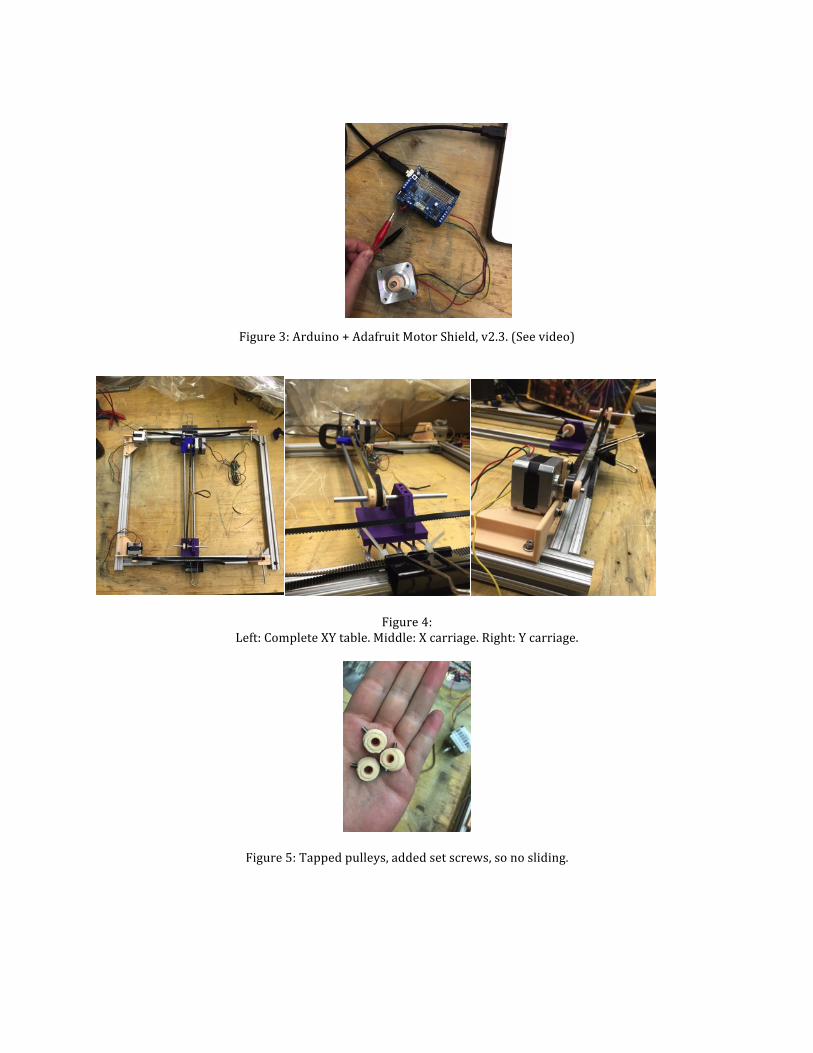
Figure3:Arduino+AdafruitMotorShield,v2.3.(Seevideo)
Figure4:Left:CompleteXYtable.Middle:Xcarriage.Right:Ycarriage.
Figure5:Tappedpulleys,addedsetscrews,sonosliding.
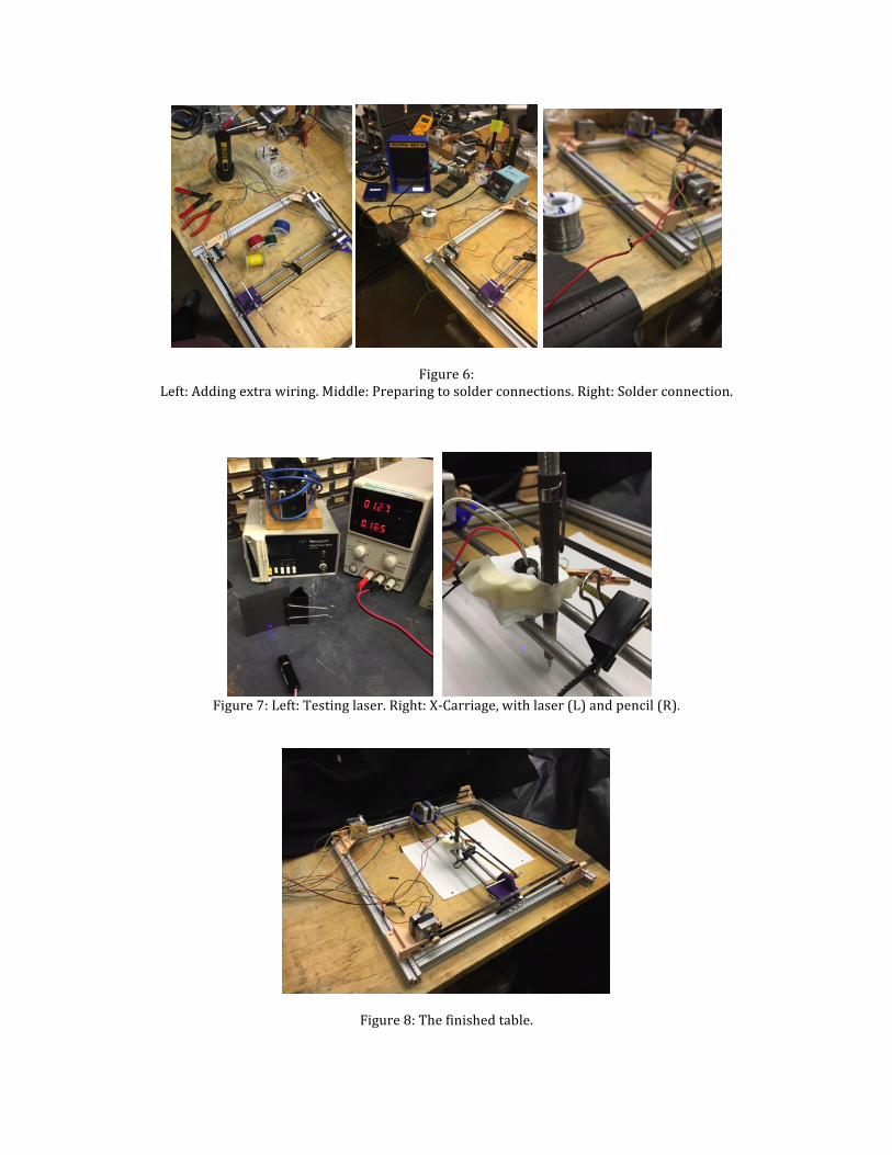
Figure6:Left:Addingextrawiring.Middle:Preparingtosolderconnections.Right:Solderconnection.
Figure7:Left:Testinglaser.Right:X-Carriage,withlaser(L)andpencil(R).
Figure8:Thefinishedtable.

Software:
From“ProjectProposal”:“Theroleofthesoftwareistotakeaninputbi-colorimage(blackandwhite),
and to do some operation on it that will translate to motion of the carriagecontainingthelaserhead.
Themethodfortranslatingbi-colorimagetoArduinomovementinstructionsinvolvestheuseofbacktracking.First,createa2Dlistcontainingpixellocationandcolor from original input image. This then becomes a ‘backtracking/floodfill’problem, different in flavor than previously encountered: wewant to go througheach pixel of the image and ask if it’s the beginning of a line. If so, look at theadjacenteightpixelsformoreblackpixels,withindicateacontinuationofthelineinthatdirection.This involvesrecursion,wherethebasecasewouldbearrivingatablackpixelthatiseither(1)surroundedbynon-blackpixelsor(2)anyblackpixelsaroundithavealreadybeenvisited.Therecursivecaseallowsusto‘climb’backupthelinetoinvestigatebranches,whereouroriginallinesplitintomultiplelines.
The total path tracedwill be stored in a list, which will be handed to the
Arduinowhenit’sfinished,sothatit’snotdoneinreal-time.”Iwrotethesoftwarecodeinsteps(versiondenotedbythe#infileof form
“LaserCutter#.py).Adescriptionof the goal of theversionwill beprovidedat thetop.Simpletestimageswillbeused,whichwillbelocatedinthesamedirectory.Iwill create separate files for Arduino control (version denoted by the # in“ArduinoPySerialTest#.ino”).
Createdanadditionalfunctionwithinmaincodetoformatthecurrentpixelpath:thefirstlocationisin(row,col)format;eachfollowingpixellocationis(drow,dcol).Splitthepathlocationsintotwoindependentcomponents,XandY,andfeedthem (alternating) to the Arduino,which relays the command to the two stackedAdafruitMotorShields.
GUIinformationcurrentlyincludes:filename,dimensionsintermsofpixels,estimatesforcuttime(basedonserialsleeptimes,numberofpixels);andaftercutinitiated:countdowntimertellshowmuchtimeleft.Fivebuttons:onetoopenfile,onetostartthecut,onetostopthecut,onetosavethepixelpathofthecutimage,andonetoreturntothewelcomepage.Atstart,“cut”,“save”and“stop”aredisabled.
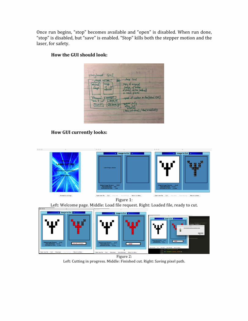
Oncerunbegins,“stop”becomesavailableand“open” isdisabled.Whenrundone,“stop”isdisabled,but“save”isenabled.“Stop”killsboththesteppermotionandthelaser,forsafety.
HowtheGUIshouldlook:
HowGUIcurrentlylooks:
Figure1:
Left:Welcomepage.Middle:Loadfilerequest.Right:Loadedfile,readytocut.
Figure2:
Left:Cuttinginprogress.Middle:Finishedcut.Right:Savingpixelpath.

Figure3:
Left:Inaseparateinstance,loadingsameimage.Right:Seesthatpixelpathalreadyexists,asksifshoulduseit.
ImprovementsIcanmake:
• Nopencil:drags/snagsanddrawsinaccuraterepresentationofwhatlaserisdoing.
• Changetrackdesign:o Instead of having x platform attached to pulley/rollers, maybe can
havey’sslidingalongrods.o Currently, sometimes the jerkingmotions fromx carriage throw the
y’sofftrack.• Usedifferentconnection,otherthanserial.
o Seems that serial connectionmust sleep at least 1.5 - 2 seconds inbetweenmovements,oryougeteithernothing,orsteppersthatwon’tstoprotating.
• Alaserthatactuallyburnsthroughpaper!o Currently have 20mW of 405nm. Not enough to even scorch black
paper.Researchsuggestsneed50mW,maybeeven100mW.Seelaserpointerforumlinkin“Resources”.
• DuringTPUserStudy,theonlysuggestionthatwasmadewasformetoaddafeature where I can allow the user to edit the image to be cut from theinterface(ex.,addapixel).Itsoundslikeagreatidea,butIcouldn’tintegrateit in the time thatwas left. [Most people thought I did an ok job; no othersuggestions.]
Imageresults:***Disclaimer:thepencilsnaggingandtrackderailingwererealproblemshere!Thelaserwasdoingwhattheserialsaid,butthepencilhasnotbeenreproducingproperly.Evenbetweentwoseparaterunsofthesameinstructions,thereweredifferences.I’veattachedthebestIcouldget.Seemsthatit’seasiertogetbestresultswithsmallerstepsizeandsimpler/smallerimages.
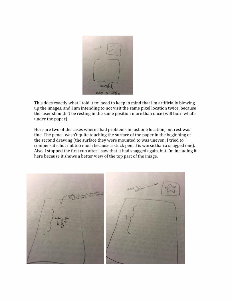
ThisdoesexactlywhatItolditto:needtokeepinmindthatI’martificiallyblowinguptheimages,andIamintendingtonotvisitthesamepixellocationtwice,becausethelasershouldn’tberestinginthesamepositionmorethanonce(willburnwhat’sunderthepaper).HerearetwoofthecaseswhereIhadproblemsinjustonelocation,butrestwasfine.Thepencilwasn’tquitetouchingthesurfaceofthepaperinthebeginningoftheseconddrawing(thesurfacetheyweremountedtowasuneven;Itriedtocompensate,butnottoomuchbecauseastuckpencilisworsethanasnaggedone).Also,IstoppedthefirstrunafterIsawthatithadsnaggedagain,butI’mincludingitherebecauseitshowsabetterviewofthetoppartoftheimage.