straight line belts • turn belts • wire cloth
TRANSCRIPT
• Straight Line Belts • Turn Belts • Wire Cloth
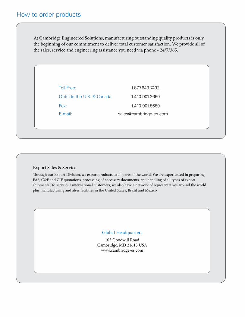
Global Headquarters105 Goodwill Road
Cambridge, MD 21613 USAwww.cambridge-es.com
Export Sales & ServiceThrough our Export Division, we export products to all parts of the world. We are experienced in preparing FAS, C&F and CIF quotations, processing of necessary documents, and handling of all types of export shipments. To serve our international customers, we also have a network of representatives around the world plus manufacturing and alses facilities in the United States, Brazil and Mexico.
At Cambridge Engineered Solutions, manufacturing outstanding quality products is only the beginning of our commitment to deliver total customer satisfaction. We provide all of the sales, service and engineering assistance you need via phone - 24/7/365.
How to order products
Toll-Free: 1.877.649.7492
Outside the U.S. & Canada: 1.410.901.2660
Fax: 1.410.901.8680
E-mail: [email protected]

Product Catalog
Welcome to Cambridge International. We’re a company with a long
history and global leadership ... but also “local small-town” values and
exceptional customer service. This catalog provides a wide variety of
information on our products, technology and expertise. Please use it to
find product details, application resources and contact information.
The catalog presents an overview of our entire product line. Cambridge
is 100% committed to helping you design the technology required to
accomplish your goals … or to enhance the efficiency and performance
of your existing operation. It’s a commitment we made nearly 100 years
ago – and one that continues just as strong today.
We would love to talk with you about your product and system needs.
Our customer experience team members are on hand to answer your
call 24 hours a day, 365 days a year (1.877.898.2923 or 1.410.901.2660).
They’re trained to answer your questions and direct you quickly to
additional resources for your convenience.
Integrity, discipline, accountability, teamwork and heartfelt commitment
are at the core of Cambridge International’s company values. These
values provide the foundation for each of us at Cambridge to respond
to your needs. Our goal is to make you a Customer for Life!
www.cambridge-es.com
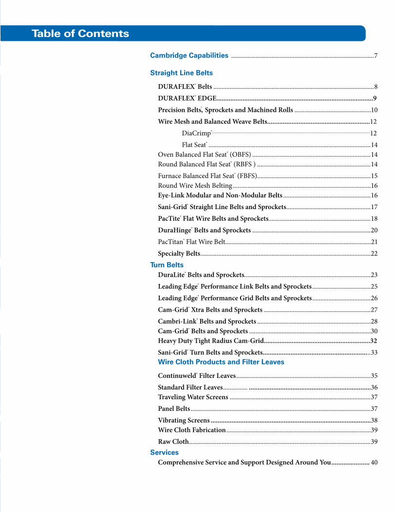
Cambridge Capabilities ........................................................................................7
Straight Line Belts
DURAFLEX® Belts ...................................................................................................8
DURAFLEX® EDGE..........................................................................................9
Precision Belts™, Sprockets and Machined Rolls ...............................................10
Wire Mesh and Balanced Weave Belts...........................................................12
DiaCrimp®.......................................................................................................................................................................12
Flat Seat® ....................................................................................................14 Oven Balanced Flat Seat® (OBFS) .........................................................................14 Round Balanced Flat Seat® (RBFS ) ......................................................................14
Furnace Balanced Flat Seat® (FBFS) ......................................................................15 Round Wire Mesh Belting .....................................................................................16 Eye-Link Modular and Non-Modular Belts ......................................................16
Sani-Grid® Straight Line Belts and Sprockets ....................................................17
PacTite® Flat Wire Belts and Sprockets ...............................................................18
DuraHinge® Belts and Sprockets .........................................................................20
PacTitan® Flat Wire Belt..........................................................................................21
Specialty Belts .........................................................................................................22
Turn BeltsDuraLite® Belts and Sprockets..............................................................................23
Leading Edge® Performance Link Belts and Sprockets ....................................25
Leading Edge® Performance Grid Belts and Sprockets ....................................26
Cam-Grid® Xtra Belts and Sprockets ..................................................................27
Cambri-Link® Belts and Sprockets ......................................................................28 Cam-Grid® Belts and Sprockets ...........................................................................30 Heavy Duty Tight Radius Cam-Grid.............................................................32
Sani-Grid® Turn Belts and Sprockets............................................................ ..33 Wire Cloth Products and Filter Leaves
Continuweld® Filter Leaves ...................................................................................35
Standard Filter Leaves ............... ......................................................................36 Traveling Water Screens .......................................................................................37
Panel Belts ...............................................................................................................37
Vibrating Screens ............................................................................................38 Wire Cloth Fabrication .........................................................................................39
Raw Cloth ................................................................................................................39Services
Comprehensive Service and Support Designed Around You ...................... 40
Table of Contents

Key Company Milestones
1911 Building completed and operations began
1915 Year of incorporation (Cambridge Wire Cloth Company)
1923 First wire belt manufactured
1953 Alloy Wire Belts founded
1964 Manufacturing and sales operations established in Mexico City
1972 Maryland Wire Belts founded
1993 Manufacturing operations established in Matamoros, Mexico
1996 Alloy Wire Belts acquired by Maryland Wire Belts
1998 Merger with Maryland Wire Belts … creation of Cambridge International
2002 Architectural Division established
2006 Brazilian manufacturing operations secured
2009 Environmental Division established

Companies all over the world rely on Cambridge International for the
widest selection of metal straight line belts, turn belts and woven wire
cloth products available from a single manufacturer.
With a heritage that extends back to 1911, we pioneered the
development of precision-engineered metal mesh conveyor belts and
wire cloth fabrications. Because of our single-minded devotion to our
craft, we continue to lead the industry today – nearly a century after
our founding.
Our commitment to the global marketplace is unmatched by any
other company in our industry. It’s exemplified by our sales and
production facilities in Mexico, as well as our Brazilian manufacturing
operation. And inside the U.S., our dominant market presence is
supported by three manufacturing and distribution facilities – two in
the East and one on the West Coast.
Being the industry leader means staying in the forefront of
innovation. No matter where you’re located, Cambridge International
stands ready to provide world-class R&D, engineering, products,
service and support. Because of our many decades of innovative
engineering and listening to customers, we can customize products
for specific applications to help you attain heightened levels of
efficiency and productivity in your operations.
This commitment to expertise and quality extends to our
manufacturing operations as well. We build every product for efficiency
and longevity, incorporating rigorous quality control and testing
procedures that ensure mechanical integrity and optimum performance.
We’re also available to provide technical advice and customer
assistance, along with “24 / 7 / 365” emergency services backed by a
100% satisfaction guarantee. Contact us toll-free at 1.877.898.2923 or
[email protected]. Let’s talk!
The Customer’s Trusted Partner for Nearly 100 Years
Among the many markets we serve:
• Food processing
– Frozen & prepared specialties
– Bakery & snack foods
– Meat, poultry & seafood processing
– Fruit & vegetable processing
– Dairy products
– Beverages & breweries
• Agricultural
• Aerospace
• Automotive
• Building & architectural
• Chemical & petrochemicals
• Electronics, semiconductors & solar cells
• Energy
• Glass & ceramics
• Metalworking
• Mining
• Packaging
Cambridge Capabilities

8
Straight Line BeltsCambridge International offers the widest range of metal straight line belt products available from a single manufacturer. Whatever your requirements, we have the solution.
Our straight line metal belts are available for friction drive and sprocket-driven applications such as washing, baking, curing, transferring and freezing.
DURAFLEX® is Cambridge International’s newest metal belt. It’s the most open metal belt available that does not compromise belt strength, can be easily retrofitted, and is easy to splice.
Mesh styles include balanced in both flattened wire and round wire varieties … self-tracking … and compound balanced, among others.
If you do not find the product you are seeking, contact us toll-free at 1.877.898.2923. Chances are, we can provide the ideal solution for your needs.
DURAFLEX® Belts
• Washing
• Baking
• General product transfer
• Battering
The most common applications where DURAFLEX® belts are used include:
• Cooling
• Coating
• Frying
• Breading
Splices in as little as 30 seconds - Our unique splice design (patent pending) can be easily spliced from the side of the unit, without weaving, using our Kwik Connect Splice Rod. The splice is as strong as the rest of the belt, so there is no weak point to fail. No special tools are needed and welding is not required! Visit www.cambridge-intl.com to watch a splice video showing how “kwik” it is.
Longer belt life - Reduced belt weight means less energy is consumed by the belt and reduced wear on units without compromising strength. Unlike other light duty conveyor belts, DURAFLEX truly hinges, thereby reducing belt fatigue and providing increased
belt life.
Easy to clean – DURAFLEX is made from food-safe stainless steel with unobstructed openings that allow for easy cleaning. Versions certified to meet rigorous 3-A sanitary standards are also available.
Increased carrying capacity - Handles heavier loads than typical light-duty conveyor belts due to the unique drive sprocket openings (patent pending), which add increased strength.
Allows for tight transfers – Small-diameter drive rolls or sprockets allow you to achieve an extremely tight transfer, reducing product damage and the loss of even small delicate products.
DURAFLEX belts are manufactured from durable, food-safe stainless steel. They are available in 3/8″ and 1/2″ pitches, and in widths from 4 to 144 inches. n
DURAFLEX® 1/2” pitch with Kwik Connect Rods
DURAFLEX® Kwik Connect Splice Rod
DURAFLEX® Sprocket, self-cleaning also available.DURAFLEX® offers smooth transport and eliminates product damage during transfer.
9
DURAFLEX® EDGE
1.54”
2.19”
2.51”
3.16”
4.12”
39.1 mm
55.6 mm
63.8 mm
80.3 mm
104.6 mm
1/2” Pitch (12.7mm Pitch)
Duraflex Sprocket Information
Outside Diameter (OD) # of Teeth Max Bore (with Keyway)
5/8”
1-1/8”
1-3/8”
1-3/4”
2-1/2”
15.9 mm
28.6 mm
34.9 mm
44.5 mm
63.5 mm
9
13
15
19
25
24”
30”
36”
42”
48”
610 mm
762 mm
914 mm
1067 mm
1219 mm
Duraflex EDGE Representative Weights
Inches Metric
1.59
1.97
2.35
2.73
3.11
2.36
2.93
3.50
4.06
4.63
Belt Width Weight
Lbs./Linear Feet KG/Linear MeterBelt Width (Range)
Belt Pitch
Flat Strip
Rod Diameter
Material
Duraflex EDGE Technical Specifications
Inches Metric
4” to 72”
1/2”
.035 x .162”
.050”
101.6 to 1828.8 mm
12.7 mm
0.9 x 4.1 mm
1.3 mmStainless Steel
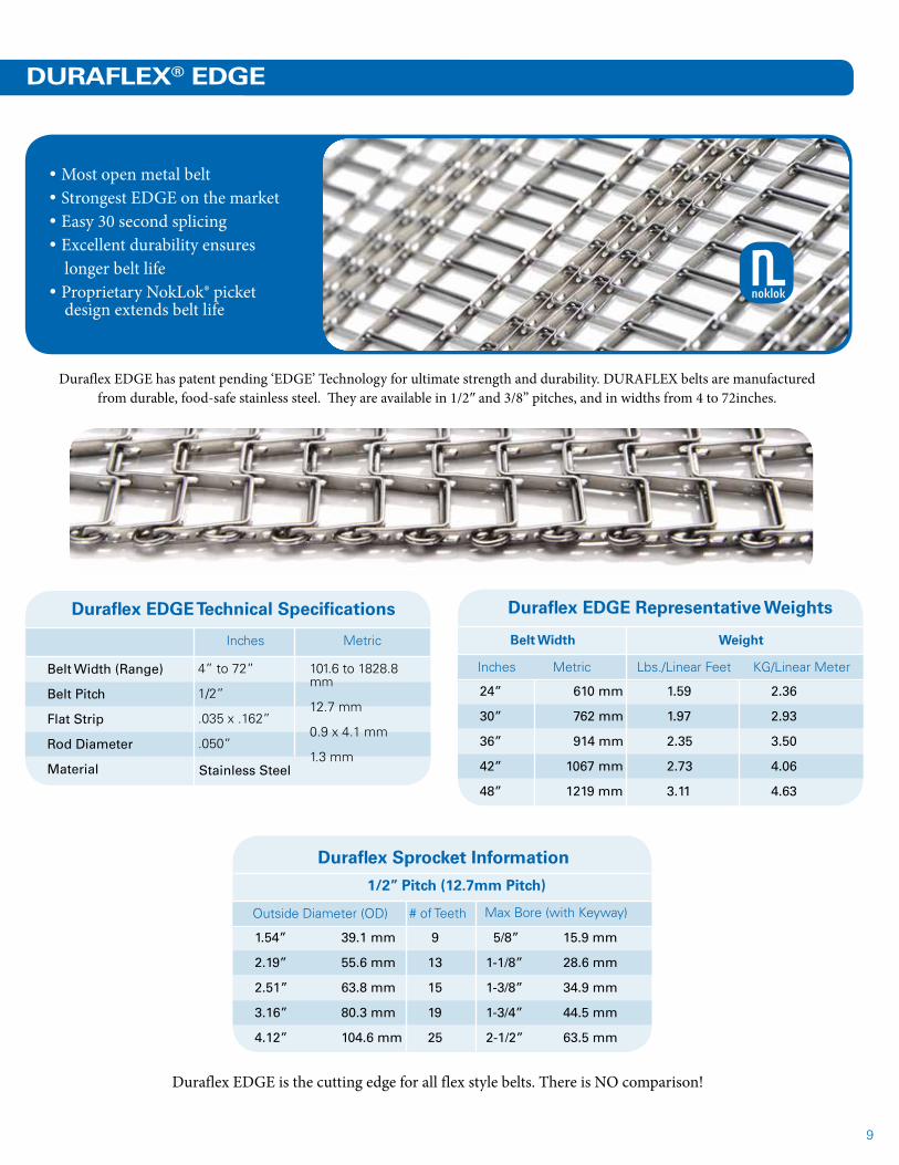
• Most open metal belt• Strongest EDGE on the market• Easy 30 second splicing• Excellent durability ensures longer belt life• Proprietary NokLok® picket design extends belt life
Duraflex EDGE has patent pending ‘EDGE’ Technology for ultimate strength and durability. DURAFLEX belts are manufactured from durable, food-safe stainless steel. They are available in 1/2″ and 3/8” pitches, and in widths from 4 to 72inches.
Duraflex EDGE is the cutting edge for all flex style belts. There is NO comparison!
noklok
10
Precision BeltsTM and Sprockets
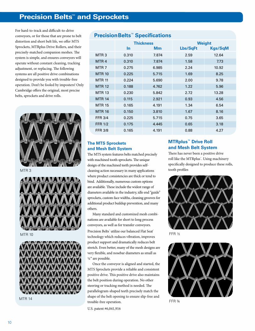
For hard-to-track and difficult-to-drive conveyors, or for those that are prone to belt distortion and short belt life, we offer MTS Sprockets, MTRplus Drive Rollers, and their precisely-matched companion meshes. The system is simple, and ensures conveyors will operate without constant cleaning, tracking adjustment, or replacing. The following systems are all positive drive combinations designed to provide you with trouble-free operation. Don’t be fooled by imposters! Only Cambridge offers the original, most precise belts, sprockets and drive rolls.
FFR ½
FFR ¾
MTR 3
MTR 10
MTR 14
The MTS Sprockets and Mesh Belt SystemThe MTS system features belts matched precisely with machined tooth sprockets. The unique design of the machined teeth provides self-cleaning action necessary in many applications where product consistencies are thick or tend to bind. Additionally, numerous custom options are available. These include the widest range of diameters available in the industry, idle end “guide” sprockets, custom face widths, cleaning grooves for additional product buildup prevention, and many others.
Many standard and customized mesh combi-nations are available for short to long process conveyors, as well as for transfer conveyors.
Precision Belts™ utilize our balanced Flat Seat® technology which reduces vibration, improves product support and dramatically reduces belt stretch. Even better, many of the mesh designs are very flexible, and nosebar diameters as small as ¼″ are possible.
Once the conveyor is aligned and started, the MTS Sprockets provide a reliable and consistent positive drive. This positive drive also maintains the belt position during operation. No other steering or tracking method is needed. The parallelogram-shaped teeth precisely match the shape of the belt opening to ensure slip-free and trouble-free operation.
U.S. patent #6,041,916
Precision BeltsTM SpecificationsThickness
In MmWeight
Lbs/SqFt Kgs/SqM
MTR 3 0.310 7.874 2.59 12.64
MTR 4 0.310 7.874 1.58 7.73
MTR 7 0.275 6.985 2.24 10.92
MTR 10 0.225 5.715 1.69 8.25
MTR 11 0.224 5.690 2.00 9.78
MTR 12 0.188 4.762 1.22 5.96
MTR 13 0.230 5.842 2.72 13.28
MTR 14 0.115 2.921 0.93 4.56
MTR 15 0.165 4.191 1.34 6.54
MTR 16 0.150 3.810 1.67 8.16
FFR 3/4 0.225 5.715 0.75 3.65
FFR 1/2 0.175 4.445 0.65 3.18
FFR 3/8 0.165 4.191 0.88 4.27
MTRplus™ Drive Roll and Mesh Belt SystemThere has never been a positive drive roll like the MTRplus™. Using machinery specifically designed to produce these rolls, tooth profiles
11
MTS Sprockets and mesh convey cheese puffs through this Lanly oven highly effectively.
Bakery products transfer delicately on an MTR 14.
Circuit boards ride smoothly on an FFR 3/8.
Cleaning groove sprockets are available for applications that are prone to product buildup.U.S. patent #5,816,988, #6,041,916
MTS Sprockets U.S. patent #5,816,988, #6,041,916
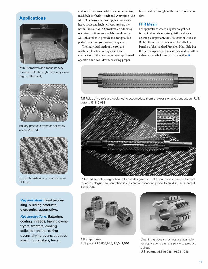
Patented self-cleaning hollow rolls are designed to make sanitation a breeze. Perfect for areas plagued by sanitation issues and applications prone to buildup. U.S. patent #7,565,967
MTRplus drive rolls are designed to accomodate thermal expansion and contraction. U.S. patent #5,816,988
Key industries: Food proces-sing, building products, electronics, automotive.
Key applications: Battering, coating, infeeds, baking ovens, fryers, freezers, cooling, collection chains, curing ovens, drying ovens, aqueous washing, transfers, firing.
and tooth locations match the corresponding mesh belt perfectly – each and every time. The MTRplus thrives in those applications where heavy loads and high temperatures are the norm. Like our MTS Sprockets, a wide array of custom options are available to allow the MTRplus roller to provide the best possible performance for your conveyor system.
The individual teeth of the roll are machined to allow for expansion and contraction of the belt during startup, normal operation and cool-down, ensuring proper
functionality throughout the entire production day.
FFR MeshFor applications where a lighter-weight belt is required, or where a straight-through clear opening is important, the FFR series of Precision Belts is the answer. This series offers all of the benefits of the standard Precision Mesh Belt, but the percentage of open area is increased to further enhance cleanability and mass reduction. n
Applications
12
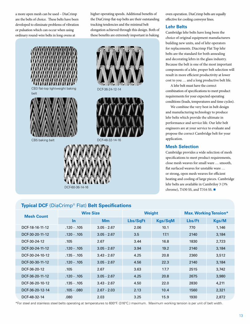
DiaCrimp® construction makes a Cambridge woven wire metal mesh belt the nearest thing yet to a universal belt! With its flat, thin spirals that deliver 25% more carrying surface than other flattened wire belts, a DiaCrimp belt is ideal for virtually any loose or containerized product in applications such as ceramic coating, glass annealing, fiberglass curing, and baking.
Available in a variety of rugged metals, these belts can handle on-belt processing of light and heavy loads, wet or dry, caustic or acid, from -100°F to +2,200°F. The extra surface area improves drive pulley contact, thereby reducing belt slippage, surging and vibration.
With its nearly perfect interface between the angled crimp seat and the diagonal angle of the spiral, a firmer, more stable seating is achieved. Better seating maximizes the bearing area and minimizes spiral movement for better tracking. By design, DiaCrimp matches perfectly the angle of the diagonal crimp with the inner curvature of the spiral for low-stress hinging, which assures longer belt life. It also results in approximately 60% less “wear-in” after a new belt is installed. (That so-called “wear-in” is actually a poorly designed belt wearing out as it stretches, seeking seating position.) Flat, thin spirals reduce belt weight,
maximize drive pulley contact, and minimize stretching and distortion. DiaCrimp belts start smooth and last far longer.
Baking BeltsFor perfectly controlled baking of cookies, bis-cuits, or cracker products, the ideal choice is a Cambridge compound balanced or DiaCrimp flat-top balanced weave baking belt. These belts are available in a variety of specifications to adapt to your particular product need. Many of the stand-ard belts are shown on the next page, including the Cambridge lightweight CB3 baking belt.
The compound balanced weave is frequently chosen for baking because of its tightly woven, flat-surface mesh which supports most dough, while permitting gases to escape for proper bottom bake.
For many hearth ovens – and wherever
DiaCrimp® Construction
Continued on next page t
Wire Mesh and Balanced Weave Belts
Of the numerous wire mesh belt styles available, balanced weave are the most frequently used belts for general conveying in food processing, metalworking, electronics, glass, and ceramics manufacturing. Balanced weaves are suggested for first consideration in all applications, unless particular design requirements dictate the use of another belt type. Providing the widest variety of strengths, meshes, wire sizes and surface characteristics, the balanced construction, with its alternating right- and left-hand spirals, is easily tracked and may be used at elevated temperatures. n
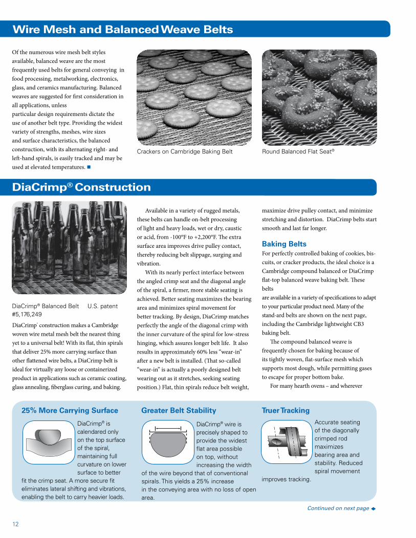
Round Balanced Flat Seat®
DiaCrimp® Balanced Belt U.S. patent #5,176,249
DiaCrimp® wire is precisely shaped to provide the widest flat area possible on top, without increasing the width
of the wire beyond that of conventional spirals. This yields a 25% increase in the conveying area with no loss of open area.
DiaCrimp® is calendared only on the top surface of the spiral, maintaining full curvature on lower surface to better
fit the crimp seat. A more secure fit eliminates lateral shifting and vibrations, enabling the belt to carry heavier loads.
Accurate seating of the diagonally crimped rod maximizes bearing area and stability. Reduced spiral movement
improves tracking.
25% More Carrying Surface Greater Belt Stability Truer Tracking
Crackers on Cambridge Baking Belt
13
CB3 flat-top lightweight baking belt
CB5 baking belt
DCF-36-24-12-14
DCF-48-32-14-16
DCF-60-36-14-16
a more open mesh can be used – DiaCrimp are the belts of choice. These belts have been developed to eliminate problems of vibration or pulsation which can occur when using ordinary round-wire belts in long ovens at
DCF-18-16-11-12 .120 - .105 3.05 - 2.67 2.06 10.1 770 1,146
DCF-30-20-11-12 .120 - .105 3.05 - 2.67 3.5 17.1 2140 3,184
DCF-30-24-12 .105 2.67 3.44 16.8 1830 2,723
DCF-30-24-11-12 .120 - .105 3.05 - 2.67 3.94 19.2 2140 3,184
DCF-30-24-10-12 .135 - .105 3.43 - 2.67 4.25 20.8 2360 3,512
DCF-30-30-11-12 .120 - .105 3.05 - 2.67 4.56 22.3 2140 3,184
DCF-36-20-12 .105 2.67 3.63 17.7 2515 3,742
DCF-36-20-11-12 .120 - .105 3.05 - 2.67 4.25 20.8 2675 3,980
DCF-36-20-10-12 .135 - .105 3.43 - 2.67 4.50 22.0 2830 4,211
DCF-36-20-12-14 .105 - .080 2.67 - 2.03 2.13 10.4 1560 2,321
DCF-48-32-14 .080 2.03 3.25 15.9 1930 2,872
*For steel and stainless steel belts operating at temperatures to 600°F. (316°C.) maximum. Maximum working tension is per unit of belt width.
Mesh Count
Wire Size Weight Max. Working Tension*
Typical DCF (DiaCrimp® Flat) Belt Specifications
higher operating speeds. Additional benefits of the DiaCrimp flat-top belts are their outstanding tracking tendencies and the minimal belt elongation achieved through this design. Both of these benefits are extremely important in baking
oven operation. DiaCrimp belts are equally effective for cooling conveyor lines.
Lehr BeltsCambridge lehr belts have long been the choice of original equipment manufacturers building new units, and of lehr operators for replacements. Diacrimp Flat Top lehr belts are the standard for both annealing and decorating lehrs in the glass industry. Because the belt is one of the most important components of a lehr, proper belt selection will result in more efficient productivity at lower cost to you … and a long productive belt life.
A lehr belt must have the correct combination of specifications to meet product requirements for your expected operating conditions (loads, temperatures and time cycles).
We combine the very best in belt design and manufacturing technology to produce lehr belts which provide the ultimate in performance and service life. Our lehr belt engineers are at your service to evaluate and propose the correct Cambridge belt for your application.
Mesh SelectionCambridge provides a wide selection of mesh specifications to meet product requirements, close mesh weaves for small ware … smooth, flat surfaced weaves for unstable ware … or strong, open mesh weaves for efficient heating and cooling of large pieces. Cambridge lehr belts are available in Cambriloy 3 (3% chrome), T430 SS, and T316 SS. n
In Mm Lbs/SqFt Kgs/SqM Lbs/Ft Kgs/M
14
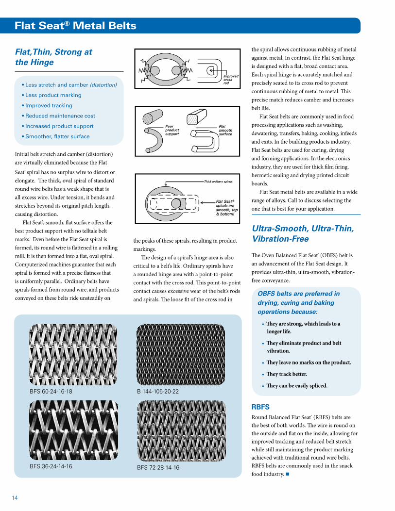
Flat Seat® Metal Belts
Initial belt stretch and camber (distortion) are virtually eliminated because the Flat
Seat® spiral has no surplus wire to distort or elongate. The thick, oval spiral of standard round wire belts has a weak shape that is all excess wire. Under tension, it bends and stretches beyond its original pitch length, causing distortion.
Flat Seat’s smooth, flat surface offers the best product support with no telltale belt marks. Even before the Flat Seat spiral is formed, its round wire is flattened in a rolling mill. It is then formed into a flat, oval spiral. Computerized machines guarantee that each spiral is formed with a precise flatness that is uniformly parallel. Ordinary belts have spirals formed from round wire, and products conveyed on these belts ride unsteadily on
• Less stretch and camber (distortion)
• Less product marking
• Improved tracking
• Reduced maintenance cost
• Increased product support
• Smoother, flatter surface
the peaks of these spirals, resulting in product markings.
The design of a spiral’s hinge area is also critical to a belt’s life. Ordinary spirals have a rounded hinge area with a point-to-point contact with the cross rod. This point-to-point contact causes excessive wear of the belt’s rods and spirals. The loose fit of the cross rod in
Flat,Thin, Strong at the Hinge
BFS 72-28-14-16
BFS 60-24-16-18
BFS 36-24-14-16
B 144-105-20-22
the spiral allows continuous rubbing of metal against metal. In contrast, the Flat Seat hinge is designed with a flat, broad contact area. Each spiral hinge is accurately matched and precisely seated to its cross rod to prevent continuous rubbing of metal to metal. This precise match reduces camber and increases belt life.
Flat Seat belts are commonly used in food processing applications such as washing, dewatering, transfers, baking, cooking, infeeds and exits. In the building products industry, Flat Seat belts are used for curing, drying and forming applications. In the electronics industry, they are used for thick film firing, hermetic sealing and drying printed circuit boards.
Flat Seat metal belts are available in a wide range of alloys. Call to discuss selecting the one that is best for your application.
Ultra-Smooth, Ultra-Thin, Vibration-Free
The Oven Balanced Flat Seat® (OBFS) belt is an advancement of the Flat Seat design. It provides ultra-thin, ultra-smooth, vibration-free conveyance.
OBFS belts are preferred in drying, curing and baking operations because:
• They are strong, which leads to a longer life.
• They eliminate product and belt vibration.
• They leave no marks on the product.
• They track better.
• They can be easily spliced.
RBFSRound Balanced Flat Seat® (RBFS) belts are the best of both worlds. The wire is round on the outside and flat on the inside, allowing for improved tracking and reduced belt stretch while still maintaining the product marking achieved with traditional round wire belts. RBFS belts are commonly used in the snack food industry. n

15
Another advancement of the Flat Seat® design is the Furnace Balanced Flat Seat® (FBFS) belt. We revolutionized furnace belts by taking our patented Flat Seat design and enhancing it for use in high temperature applications. Designed to replace the old-fashioned Double Balanced belting, our FBFS belt weighs far less without compromising strength and durability. FBFS has no excess wire to stretch and camber (wavy distortion across the belt width), like Double Balanced belts where stretch is an on going problem.
The antiquated Double Balanced design’s thick, overlapping spirals lengthen and flatten during each cycle through a furnace due to the excess wire. The result is stretch and camber which prevents the belt from hinging and tracking properly, eventually destroying the belt itself.
Stretch is an ongoing and costly problem. It must be removed and this requires frequent downtime, incurring additional expense
Furnace Balanced Flat Seat® Belts
FBFS 24-10-8-10
beyond just the purchase cost of the belt. Additionally, all of the excess wire in a Double Balanced furnace belt is useless weight that must be heated and cooled with each cycle. This leads to useless energy consumption and increased energy cost, again adding more expense beyond the purchase price of the belt. With no excess wire to stretch and camber the simple, efficient, single wire spiral design of our FBFS belt requires less energy to operate, stretches less, reduces downtime, and makes splicing easier.
Numerous edge treatments are available for finishing furnace belts. Our skilled craftsmen have extensive experience producing both the knuckled and welded edge and the trimmed and welded edge. Other special edge treatments are available if needed.
The choice of the appropriate alloy is an important decision which will affect belt life and cost. There is often a trade-off between the two, and the decision will be based on the historical experience with the belting used in your application, where the only variable has been the alloy.
T 314 stainless steel offers economy, oxidation resistance and high-temperature strength. The high silicon content is very important for adding adhesion to the high temperature scale. It is used in temperatures up to 1,600°F (870°C) in air and up to 2,100°F (1150°C) in protected environments.
35-19CB is the next step in oxidation resistance. It is more carburization-resistant than T 314 in many applications. This stabilized alloy is proven superior in resisting corrosion and carbon embrittlement. 35-19CB is not commonly susceptible to preferential oxidation (green rot). It is used in temperatures up to 1,800°F (980°C) in air and up to 2,150°F (1,200°C) in protected environments.
80-20CB, Inconel 601 and Tophet 30 are additional choices of high temperature alloys. These alloys solve specific problems caused by temperature, atmosphere, and process.
Through decreased downtime, energy savings, and with fewer belt replacements, each FBFS belt you order helps pay for itself. Years of experience in working with
FBFS-42-18-10-12
A damaged Double Balanced weave belt after five months of use. Note the camber and broken wires.
For High Temperature Applications:
• Annealing Furnaces
• Brazing Furnaces
• Sintering Furnaces
• Wrapper Belts
• Foundry Applications
customers in high temperature industries gives us the advantage in helping you choose your best furnace belt. Contact us today to make sure you are using the most economical and appropriate mesh and alloy for your application. n
Cambridge FBFS belts handle heavy loads with ease.
16
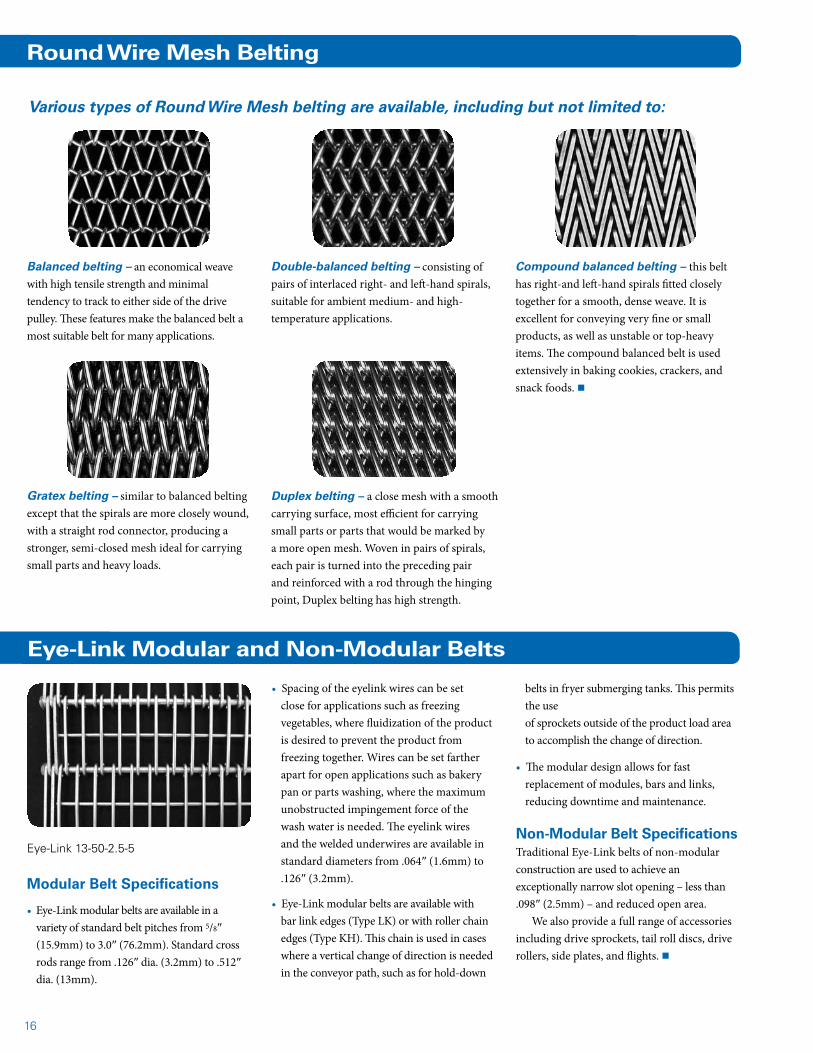
Duplex belting – a close mesh with a smooth carrying surface, most efficient for carrying small parts or parts that would be marked by a more open mesh. Woven in pairs of spirals, each pair is turned into the preceding pair and reinforced with a rod through the hinging point, Duplex belting has high strength.
Compound balanced belting – this belt has right-and left-hand spirals fitted closely together for a smooth, dense weave. It is excellent for conveying very fine or small products, as well as unstable or top-heavy items. The compound balanced belt is used extensively in baking cookies, crackers, and snack foods. n
Round Wire Mesh Belting
Various types of Round Wire Mesh belting are available, including but not limited to:
Modular Belt Specifications
• Eye-Link modular belts are available in a variety of standard belt pitches from 5/8″ (15.9mm) to 3.0″ (76.2mm). Standard cross rods range from .126″ dia. (3.2mm) to .512″ dia. (13mm).
Eye-Link Modular and Non-Modular Belts
• Spacing of the eyelink wires can be set close for applications such as freezing vegetables, where fluidization of the product is desired to prevent the product from freezing together. Wires can be set farther apart for open applications such as bakery pan or parts washing, where the maximum unobstructed impingement force of the wash water is needed. The eyelink wires and the welded underwires are available in standard diameters from .064″ (1.6mm) to .126″ (3.2mm).
• Eye-Link modular belts are available with bar link edges (Type LK) or with roller chain edges (Type KH). This chain is used in cases where a vertical change of direction is needed in the conveyor path, such as for hold-down
belts in fryer submerging tanks. This permits the use of sprockets outside of the product load area to accomplish the change of direction.
• The modular design allows for fast replacement of modules, bars and links, reducing downtime and maintenance.
Non-Modular Belt SpecificationsTraditional Eye-Link belts of non-modular construction are used to achieve an exceptionally narrow slot opening – less than .098″ (2.5mm) – and reduced open area.
We also provide a full range of accessories including drive sprockets, tail roll discs, drive rollers, side plates, and flights. n
Eye-Link 13-50-2.5-5
Balanced belting – an economical weave with high tensile strength and minimal tendency to track to either side of the drive pulley. These features make the balanced belt a most suitable belt for many applications.
Double-balanced belting – consisting of pairs of interlaced right- and left-hand spirals, suitable for ambient medium- and high-temperature applications.
Gratex belting – similar to balanced belting except that the spirals are more closely wound, with a straight rod connector, producing a stronger, semi-closed mesh ideal for carrying small parts and heavy loads.
17
Sani-Grid® Sprockets for Straight Line Belts
Sprocket No. of Belt Pitch Pitch Dia. Outside Dia. Approx Wt. Bore Size
No. Teeth
5-12* 12 3/4 19.1 2.898 73.6 3.159 80.2 1.68 0.76 3/4 - 1 1/8
7-11* 11 5/8 15.9 2.218 56.3 2.500 63.5 0.97 0.44 3/4 - 1 1/8
7-13* 13 5/8 15.9 2.612 66.3 2.875 73.0 1.22 0.55 3/4 - 1 1/8
7-15* 15 5/8 15.9 3.006 76.4 3.250 82.6 1.60 0.73 3/4 - 1 1/8
9-11 11 1/2 12.7 1.775 45.1 1.938 49.2 0.57 0.26 3/4 - 13/16
9-14 14 1/2 12.7 2.247 57.1 2.500 63.5 0.90 0.41 3/4 - 7/8
9-16 16 1/2 12.7 2.546 64.7 2.750 69.9 1.22 0.55 3/4 - 1 1/8
9-19 19 1/2 12.7 3.038 77.2 3.250 82.6 1.82 0.83 3/4 - 1 3/8
9-25 25 1/2 12.7 3.989 101.3 4.250 108.0 3.41 1.55 3/4 - 1 7/8
5 Gauge (.207” 5.26 Mm)
7 Gauge (.177” 4.50 Mm)
9 Gauge (.148” 3.76 Mm)
All sprockets available in T-303 stainless steel. *Also available in UHMWPE. (Sprocket numbers 5-12, 7-13, and 7-15 are two-piece sprockets, with UHMWPE outer ring and stainless steel hubset.)
Belt Width* 5 Ga. 7 Ga. 9 Ga.
In Mm Lbs Kg Lbs Kg Lbs Kg
12 304.8 2.34 3.48 1.98 2.95 1.68 2.50
15 381.0 2.79 4.15 2.38 3.54 2.03 3.02
18 457.2 3.25 4.84 2.78 4.14 2.38 3.54
20 508.0 3.55 5.28 3.07 4.57 — —
24 609.6 4.16 6.19 3.59 5.34 3.01 4.48
30 762.0 5.07 7.54 4.39 6.53 3.71 5.52
36 914.4 5.98 8.90 5.19 7.72 — —
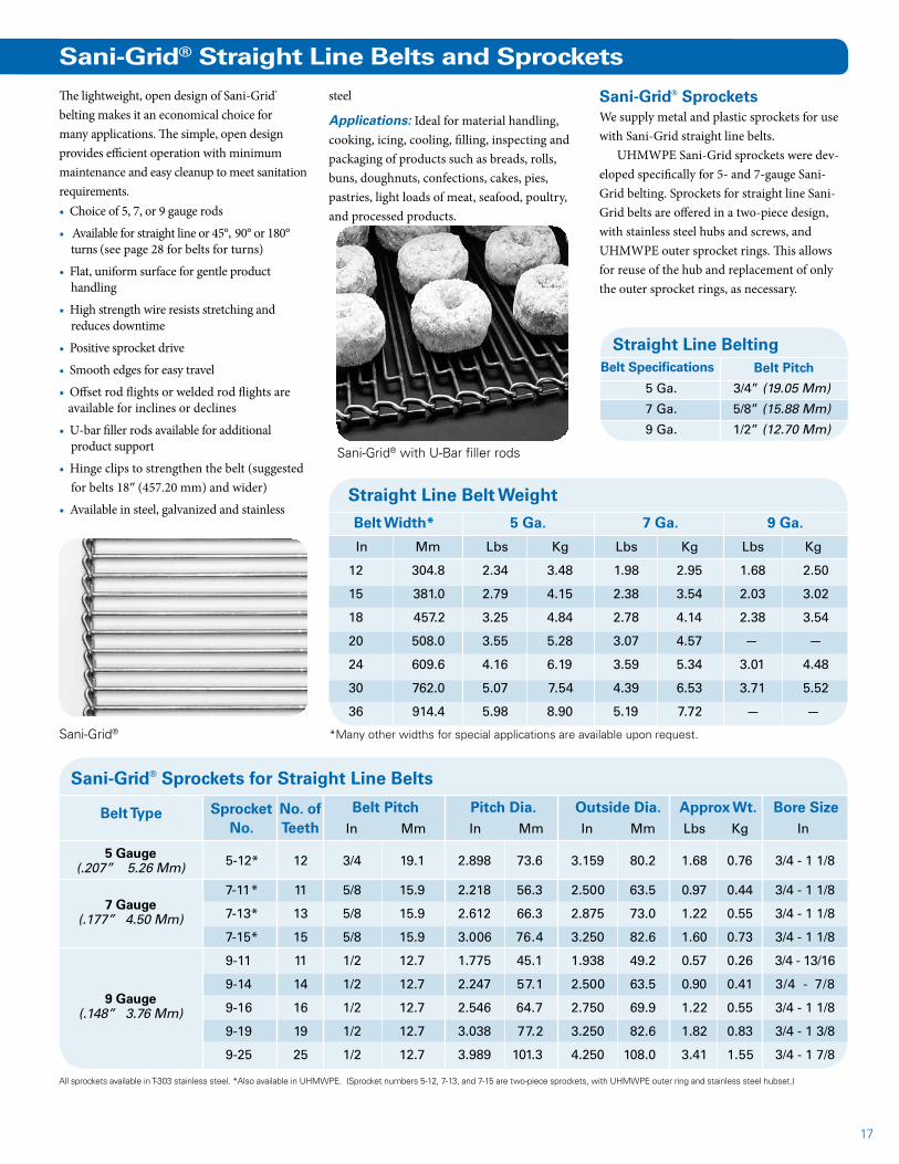
Sani-Grid® SprocketsWe supply metal and plastic sprockets for use with Sani-Grid straight line belts.
UHMWPE Sani-Grid sprockets were dev-eloped specifically for 5- and 7-gauge Sani-Grid belting. Sprockets for straight line Sani-Grid belts are offered in a two-piece design, with stainless steel hubs and screws, and UHMWPE outer sprocket rings. This allows for reuse of the hub and replacement of only the outer sprocket rings, as necessary.
Sani-Grid® Straight Line Belts and Sprockets
The lightweight, open design of Sani-Grid® belting makes it an economical choice for many applications. The simple, open design provides efficient operation with minimum maintenance and easy cleanup to meet sanitation requirements. • Choice of 5, 7, or 9 gauge rods
• Available for straight line or 45°, 90° or 180° turns (see page 28 for belts for turns)
• Flat, uniform surface for gentle product handling
• High strength wire resists stretching and reduces downtime
• Positive sprocket drive
• Smooth edges for easy travel
• Offset rod flights or welded rod flights are available for inclines or declines
• U-bar filler rods available for additional product support
• Hinge clips to strengthen the belt (suggested for belts 18″ (457.20 mm) and wider)
• Available in steel, galvanized and stainless
Sani-Grid®
steel
Applications: Ideal for material handling, cooking, icing, cooling, filling, inspecting and packaging of products such as breads, rolls, buns, doughnuts, confections, cakes, pies, pastries, light loads of meat, seafood, poultry, and processed products.
Sani-Grid® with U-Bar filler rods
In Mm In Mm In Mm Lbs Kg In
5 Ga. 3/4” (19.05 Mm)
7 Ga. 5/8” (15.88 Mm)
9 Ga. 1/2” (12.70 Mm)
Straight Line Belting Belt Specifications Belt Pitch
*Many other widths for special applications are available upon request.
Belt Type
Straight Line Belt Weight
18
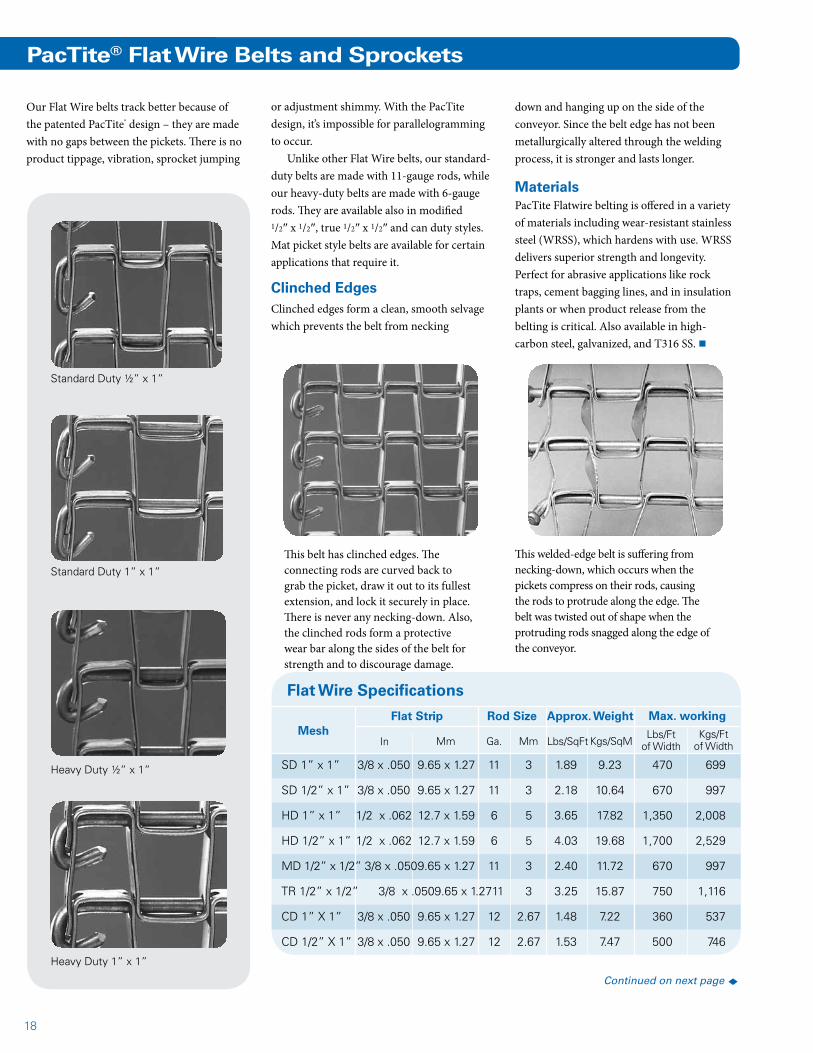
Our Flat Wire belts track better because of the patented PacTite® design – they are made with no gaps between the pickets. There is no product tippage, vibration, sprocket jumping
Heavy Duty ½” x 1”
Heavy Duty 1” x 1”
Standard Duty ½” x 1”
Standard Duty 1” x 1”
PacTite® Flat Wire Belts and Sprockets
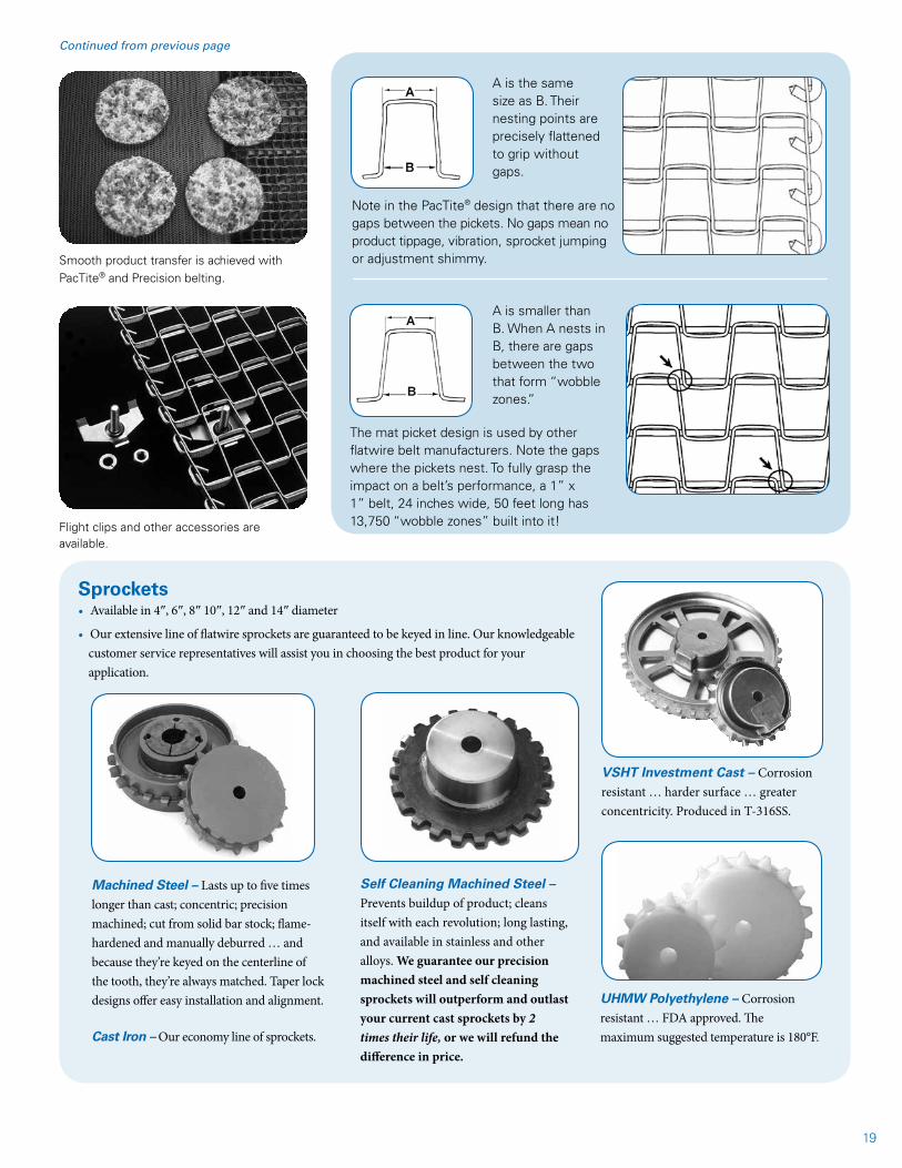
This belt has clinched edges. The connecting rods are curved back to grab the picket, draw it out to its fullest extension, and lock it securely in place. There is never any necking-down. Also, the clinched rods form a protective wear bar along the sides of the belt for strength and to discourage damage.
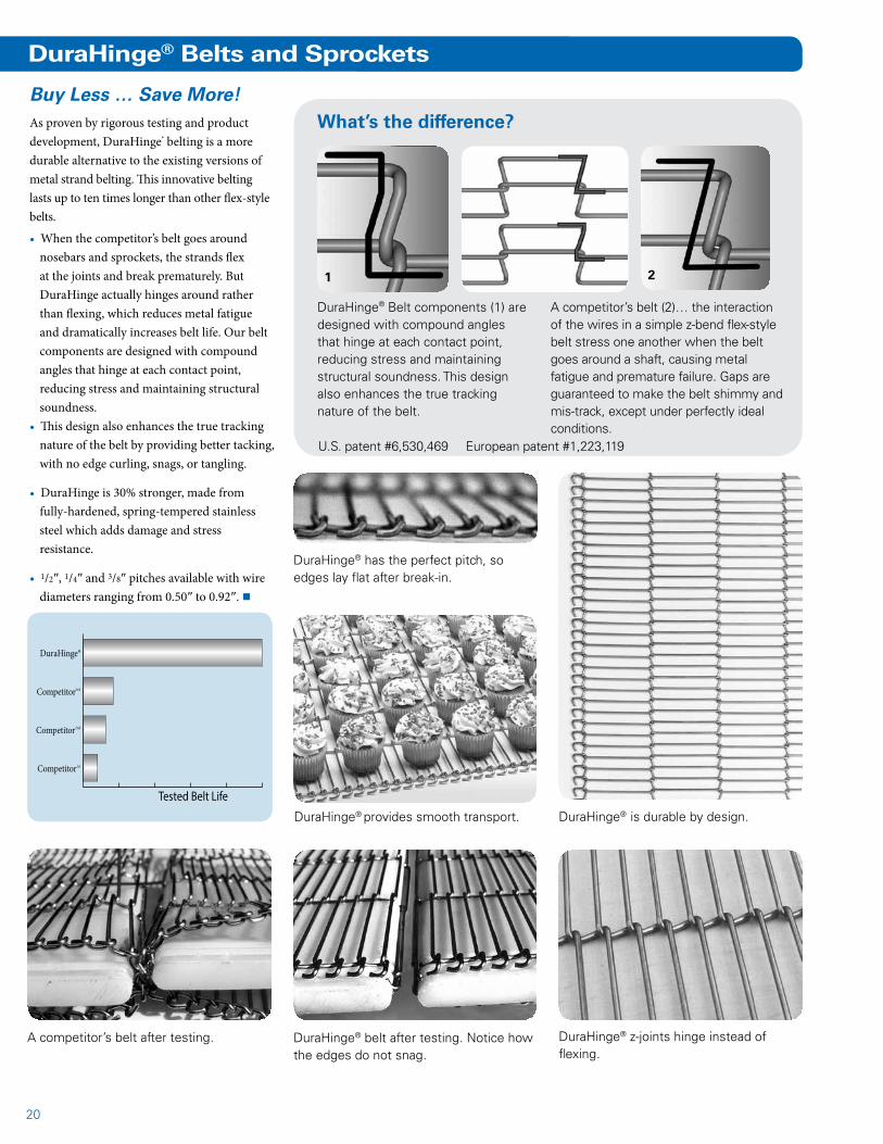
This welded-edge belt is suffering from necking-down, which occurs when the pickets compress on their rods, causing the rods to protrude along the edge. The belt was twisted out of shape when the protruding rods snagged along the edge of the conveyor.
or adjustment shimmy. With the PacTite design, it’s impossible for parallelogramming to occur.
Unlike other Flat Wire belts, our standard-duty belts are made with 11-gauge rods, while our heavy-duty belts are made with 6-gauge rods. They are available also in modified 1/2″ x 1/2″, true 1/2″ x 1/2″ and can duty styles. Mat picket style belts are available for certain applications that require it.
Clinched EdgesClinched edges form a clean, smooth selvage which prevents the belt from necking
down and hanging up on the side of the conveyor. Since the belt edge has not been metallurgically altered through the welding process, it is stronger and lasts longer.
MaterialsPacTite Flatwire belting is offered in a variety of materials including wear-resistant stainless steel (WRSS), which hardens with use. WRSS delivers superior strength and longevity. Perfect for abrasive applications like rock traps, cement bagging lines, and in insulation plants or when product release from the belting is critical. Also available in high-carbon steel, galvanized, and T316 SS. n
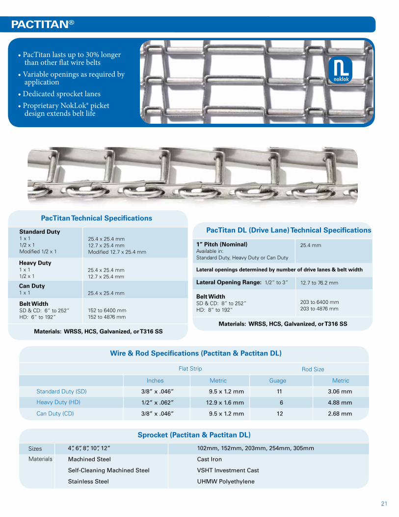
Flat Wire Specifications
MeshFlat Strip Rod Size Approx. Weight
Kgs/SqMLbs/SqFtMmGa.MmIn
SD 1” x 1” 3/8 x .050 9.65 x 1.27 11 3 1.89 9.23 470 699
SD 1/2” x 1” 3/8 x .050 9.65 x 1.27 11 3 2.18 10.64 670 997
HD 1” x 1” 1/2 x .062 12.7 x 1.59 6 5 3.65 17.82 1,350 2,008
HD 1/2” x 1” 1/2 x .062 12.7 x 1.59 6 5 4.03 19.68 1,700 2,529
MD 1/2” x 1/2” 3/8 x .050 9.65 x 1.27 11 3 2.40 11.72 670 997
TR 1/2” x 1/2” 3/8 x .050 9.65 x 1.27 11 3 3.25 15.87 750 1,116
CD 1” X 1” 3/8 x .050 9.65 x 1.27 12 2.67 1.48 7.22 360 537
CD 1/2” X 1” 3/8 x .050 9.65 x 1.27 12 2.67 1.53 7.47 500 746
Lbs/Ft of Width
Max. working
Kgs/Ft of Width
Continued on next page t
19
UHMW Polyethylene – Corrosion resistant … FDA approved. The maximum suggested temperature is 180°F.
Sprockets• Available in 4″, 6″, 8″ 10″, 12″ and 14″ diameter
• Our extensive line of flatwire sprockets are guaranteed to be keyed in line. Our knowledgeable customer service representatives will assist you in choosing the best product for your application.
Machined Steel – Lasts up to five times longer than cast; concentric; precision machined; cut from solid bar stock; flame-hardened and manually deburred … and because they’re keyed on the centerline of the tooth, they’re always matched. Taper lock designs offer easy installation and alignment.
Self Cleaning Machined Steel – Prevents buildup of product; cleans itself with each revolution; long lasting, and available in stainless and other alloys. We guarantee our precision machined steel and self cleaning sprockets will outperform and outlast your current cast sprockets by 2 times their life, or we will refund the difference in price.
VSHT Investment Cast – Corrosion resistant … harder surface … greater concentricity. Produced in T-316SS.
Cast Iron – Our economy line of sprockets.
A is the same size as B. Their nesting points are precisely flattened to grip without gaps.
Note in the PacTite® design that there are no gaps between the pickets. No gaps mean no product tippage, vibration, sprocket jumping or adjustment shimmy.
A is smaller than B. When A nests in B, there are gaps between the two that form “wobble zones.”
The mat picket design is used by other flatwire belt manufacturers. Note the gaps where the pickets nest. To fully grasp the impact on a belt’s performance, a 1” x 1” belt, 24 inches wide, 50 feet long has 13,750 “wobble zones” built into it!
Smooth product transfer is achieved with PacTite® and Precision belting.
Flight clips and other accessories are available.
Continued from previous page
20
DuraHinge® z-joints hinge instead of flexing.
DuraHinge® Belt components (1) are designed with compound angles that hinge at each contact point, reducing stress and maintaining structural soundness. This design also enhances the true tracking nature of the belt.
A competitor’s belt (2)… the interaction of the wires in a simple z-bend flex-style belt stress one another when the belt goes around a shaft, causing metal fatigue and premature failure. Gaps are guaranteed to make the belt shimmy and mis-track, except under perfectly ideal conditions.
1 2
DuraHinge® provides smooth transport.
What’s the difference?Buy Less … Save More!As proven by rigorous testing and product development, DuraHinge® belting is a more durable alternative to the existing versions of metal strand belting. This innovative belting lasts up to ten times longer than other flex-style belts.
• When the competitor’s belt goes around nosebars and sprockets, the strands flex at the joints and break prematurely. But DuraHinge actually hinges around rather than flexing, which reduces metal fatigue and dramatically increases belt life. Our belt components are designed with compound angles that hinge at each contact point, reducing stress and maintaining structural soundness.
• This design also enhances the true tracking nature of the belt by providing better tacking, with no edge curling, snags, or tangling.
• DuraHinge is 30% stronger, made from fully-hardened, spring-tempered stainless steel which adds damage and stress resistance.
• 1/2″, 1/4″ and 3/8″ pitches available with wire diameters ranging from 0.50″ to 0.92″. n
DuraHinge® Belts and Sprockets
DuraHinge® has the perfect pitch, so edges lay flat after break-in.
Competitor1st
Competitor2nd
Competitor3rd
DuraHinge®
Tested Belt Life
DuraHinge® belt after testing. Notice how the edges do not snag.
DuraHinge® is durable by design.
A competitor’s belt after testing.
U.S. patent #6,530,469 European patent #1,223,119
21
PACTITAN®
Wire & Rod Specifications (Pactitan & Pactitan DL)
Inches
PacTitan Technical Specifications
• PacTitan lasts up to 30% longer than other flat wire belts
• Variable openings as required by application
• Dedicated sprocket lanes• Proprietary NokLok® picket
design extends belt life
Sprocket (Pactitan & Pactitan DL)
Sizes 4”, 6”, 8”, 10”, 12”
Machined Steel
Self-Cleaning Machined Steel
Stainless Steel
102mm, 152mm, 203mm, 254mm, 305mm
Cast Iron
VSHT Investment Cast
UHMW Polyethylene
Metric Guage Metric
Flat Strip Rod Size
Standard Duty (SD)
Heavy Duty (HD)
Can Duty (CD)
3/8” x .046”
1/2” x .062”
3/8” x .046”
9.5 x 1.2 mm
12.9 x 1.6 mm
9.5 x 1.2 mm
11
6
12
3.06 mm
4.88 mm
2.68 mm
Materials
Standard Duty1 x 11/2 x 1Modified 1/2 x 1
25.4 x 25.4 mm12.7 x 25.4 mmModified 12.7 x 25.4 mm
Heavy Duty1 x 11/2 x 1
25.4 x 25.4 mm12.7 x 25.4 mm
Can Duty1 x 1 25.4 x 25.4 mm
Belt WidthSD & CD: 6” to 252”HD: 6” to 192”
152 to 6400 mm152 to 4876 mm
Materials: WRSS, HCS, Galvanized, or T316 SS
PacTitan DL (Drive Lane) Technical Specifications
1” Pitch (Nominal)Available in:Standard Duty, Heavy Duty or Can Duty
25.4 mm
Materials: WRSS, HCS, Galvanized, or T316 SS
Lateral openings determined by number of drive lanes & belt width
Lateral Opening Range: 1/2” to 3” 12.7 to 76.2 mm
Belt WidthSD & CD: 8” to 252”HD: 8” to 192”
203 to 6400 mm203 to 4876 mm
noklok

22
Precision roller chain, duplex weave with journaled rod every 4th pitch.
Precision roller chain, balanced weave with rods passing through holes in the side bars.
Angle Flights
Conventional Weave
Balanced weave mesh with standard roller chain.
Shot-blast Belt
Cradle Belt
Specialty Belts
Chain-Driven Metal Mesh BeltsChain-driven metal mesh belts should be considered whenever timing, transfer, and/or positive belt drive are important … in cases such as travel-up inclines, under heavy loads, for long distances, through quenching liquids, cooking oils or other slippery conditions.
Chain-driven belts are also the only belts that are self supporting. They can provide efficient operation in applications where friction-driven belts would not be desirable. Any mesh can be used in a chain-driven
construction, but the selection is made on the basis of what is needed to support the product.
Balanced weave should be given first consideration, as it is economical and appropriate for most conditions. Gratex weave provides a closer mesh, while a Duplex weave is a close mesh that also provides strength and a straight through opening. A conventional weave provides unobstructed openings.
Typical ApplicationsIn food processing, chain-driven belts are used in washing, drying, cooking, freezing, dewatering and blanching operations. In other applications, metals, electronic parts, chemicals, ceramics, leather, lumber, textiles, rubber and many other products are moved through a host of processes where positive drive is needed.
Chain SelectionChain is normally selected according to the strength and speed required. The most frequently used types of chain for metal mesh conveyors are roller chain, employed for most room-to-medium temperature applications, and pintle chain which is recommended for heavier loads and higher temperatures.
Due to the important and specialized nature of the applications requiring these products, each inquiry is reviewed thoroughly. Our goal is to supply the most suitable belt for your specific application. We strive to provide solutions for each situation, assuring value for our customers. Our engineers and technical support group are involved in every specialty belt inquiry and order. n
Precision roller chain, balanced weave with rods every pitch.
Up-turned Edge
Pintle Chain and Side Plates
23
strength-to-belt weight ratio on today’s market ... twice as strong as rod-only belts ... and 35% stronger than standard 1″ x 1″ style belts.
Improved efficiency – Our unique 3″ x 1″ interior mesh chills and freezes foods faster by improving air circulation and drainage.
Stronger yet lighter-weight – A belt that’s up to 40% lighter means less wear on the belt and cage components, thereby saving energy while greatly reducing potential debris.
One style works for all spiral cage applications – With turn ratios ranging
Turn Belts
Cambridge International offers the widest range of metal belt products available from a single manufacturer. Whatever your requirements – from a simple rods-only belt to achieving the precise balance between open areas and product support – we have the solution.
Long recognized for our leader-ship in the design and manufacture of spiral cage and turn belting for a wide variety of high-performance belt systems, we work closely with
you to develop and deliver the best, most effective product solution for each specific application. Our turn belts are the industry’s proven performers – running smoothly and dependably year after year in the spiral system installations of production plants throughout the world.
If you do not find the turn belt product you are seeking, contact us toll-free at 1.877.898.2923. Chances are, we can provide the ideal solution for your needs.
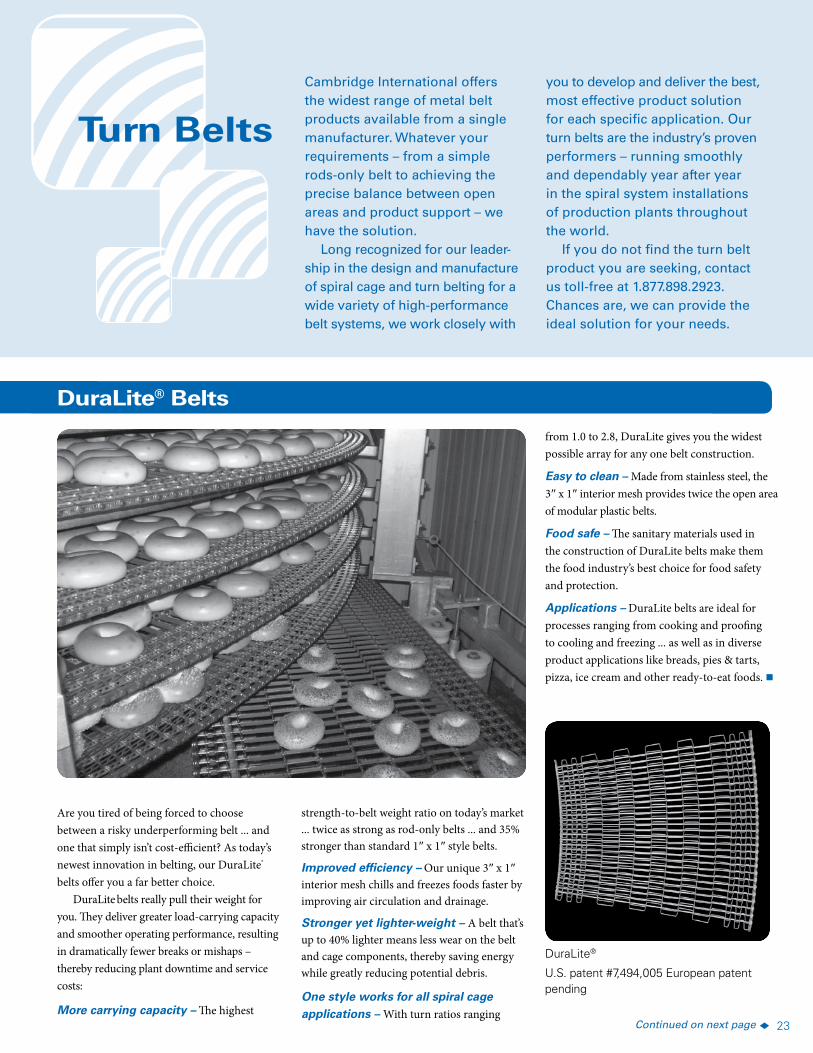
DuraLite® Belts
DuraLite®
Are you tired of being forced to choose between a risky underperforming belt ... and one that simply isn’t cost-efficient? As today’s newest innovation in belting, our DuraLite® belts offer you a far better choice.
DuraLite belts really pull their weight for you. They deliver greater load-carrying capacity and smoother operating performance, resulting in dramatically fewer breaks or mishaps – thereby reducing plant downtime and service costs:
More carrying capacity – The highest Continued on next page t
from 1.0 to 2.8, DuraLite gives you the widest possible array for any one belt construction.
Easy to clean – Made from stainless steel, the 3″ x 1″ interior mesh provides twice the open area of modular plastic belts.
Food safe – The sanitary materials used in the construction of DuraLite belts make them the food industry’s best choice for food safety and protection.
Applications – DuraLite belts are ideal for processes ranging from cooking and proofing to cooling and freezing ... as well as in diverse product applications like breads, pies & tarts, pizza, ice cream and other ready-to-eat foods. n
U.S. patent #7,494,005 European patent pending
24
DuraLite® Specifications Belt Pitch: 1.33″ (33.8 mm)
Mesh Size: 1″ x 1″ (nominal) on outer edges and 3″x 1″ (nominal) in the belt’s interior – two times stronger than rod-only belt designs and 35% stronger than conventional 1″ x 1″ style cage belts
Extra Heavy-Duty Flat Strip: 1/2″ x .0625″ (12.7 mm x 1.59 mm)
Extra Heavy-Duty Rods: 6 gauge, 0.192″ (5.9 mm) diameter
Outer Edge Construction: Double extra heavy-duty reinforcing bars (standard)
Belt Width Range: 24″ to 56″ (610 mm to 1,422 mm) overall (standard) … other widths also available
Materials: Wear-resistant stainless steel (WRSS) throughout (standard) … also available in T-304, T-316 or high carbon steel
Welding: Button-head welds on rods
Sprockets: 14 tooth, 6.34″ OD, extra heavy-duty sprocket. UHMW material (standard) … stainless and carbon steel also available on request
Special Constructions: Contact us for side-plates, lane dividers and flight availability
A sprocket drive provides a smooth, positive means of driving the belt, serves to keep the belt properly aligned and provides accurate synchronization of belt movement with operations.
In Mm In Mm In Mm In Mm In Mm In In Mm Lbs Kg
6 152.4 14T
6.340 161.0 5.991 152.2 5.32 135.1 2.0 50.8 0.937 - 2.5 2.0 50.8 1.8 0.82
Available in extra heavy-duty UHMW and stainless steel.
DuraLite® Sprockets
Nom. Dia. No. Teeth/Sprocket Designation
Overall Dia. Pitch Dia. Hub Dia. (Bottom Dia.)
Hub Length Bore Size Face Width Approx. Wt.
Continued from previous page
24 610 4.73 7.04
26 660 5.08 7.56
28 711 5.43 8.08
30 762 5.78 8.60
32 813 6.13 9.12
34 864 6.48 9.64
36 914 6.83 10.16
38 965 7.17 10.67
40 1,016 7.52 11.19
42 1,067 7.87 11.71
44 1,118 8.22 12.23
46 1,168 8.57 12.75
48 1,219 8.92 13.28
50 1,270 9.27 13.80
52 1,321 9.62 14.32
54 1,372 9.97 14.84
56 1,422 10.31 15.34
* Weights do not include bar weights.
Weight per Unit Length of Belt
Lbs/Lin Ft Kg/Lin M
Weight of DuraLite® Belts (Non-Reinforced)*
Belt Width
In Mm
• More carrying capacity
• Improved efficiency
• Stronger … yet lighter-weight
• One style works for all spiral cage applications
• Easy to clean
• Food safe
DuraLite® Rebar Weight Table
Turn Ratio Radius Type Add Lbs/Lin Ft Add Kg/Lin M
1.00 - 1.34 Super-tight 0.30 0.45
1.35 - 1.59 Tight 0.45 0.67
1.60 - 1.99 Reduced 0.50 0.74
2.00 - 2.39 Standard 0.60 0.89
2.40 - 2.80 Oversize 0.67 1.00
Tension Limits for DuraLite® Belts
Straight Running Turn or Spiral Belt Material
Application Application
WRSS 850 lbs. per ft. of width 400
T-304 or T-316 650 lbs. per ft. of width 300
Carbon Steel 850 lbs. per ft. of width 400
25
SpecificationsBelt Pitch: 1″ (25.4 mm) nominalMesh: 1″ x 1″ or 1/2″ x 1″Materials: Wear-resistant stainless steel (WRSS)Belt Turning Radius: Down to 1.5 x belt width
Warranty: 10 year/50,000 duty cycle limited service life warranty. U.S. Patent: #5,934,448
A sprocket drive provides a smooth, positive means of driving the belt, serves to keep the belt properly aligned and provides accurate synchronization of belt movement with operations.
No. Teeth/Sprocket Designation Pitch Dia. Bottom Dia. Hub Length Bore Size
Sprocket Thickness
Approx. Wt.
In Mm In Mm In Mm In In Mm Lbs Kg
18E 6.117 155.4 5.617 142.7 2.0 50.8 1.0 - 4.0 2.0 50.8 1.6 0.74
23E 7.875 200.0 7.368 187.1 2.0 50.8 1.0 - 4.0 2.0 50.8 2.9 1.31
Available in UHMW and stainless steel.
Leading Edge® Performance Link Sprockets
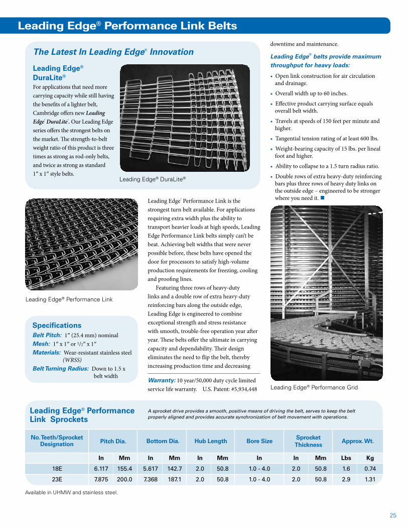
Leading Edge® Performance Link is the strongest turn belt available. For applications requiring extra width plus the ability to transport heavier loads at high speeds, Leading Edge Performance Link belts simply can’t be beat. Achieving belt widths that were never possible before, these belts have opened the door for processors to satisfy high-volume production requirements for freezing, cooling and proofing lines.
Featuring three rows of heavy-duty links and a double row of extra heavy-duty reinforcing bars along the outside edge, Leading Edge is engineered to combine exceptional strength and stress resistance with smooth, trouble-free operation year after year. These belts offer the ultimate in carrying capacity and dependability. Their design eliminates the need to flip the belt, thereby increasing production time and decreasing
Leading Edge® Performance Link
Leading Edge® Performance Link Belts
Leading Edge® DuraLite®
Leading Edge® DuraLite®
For applications that need more carrying capacity while still having the benefits of a lighter belt, Cambridge offers new Leading Edge® DuraLite®. Our Leading Edge series offers the strongest belts on the market. The strength-to-belt weight ratio of this product is three times as strong as rod-only belts, and twice as strong as standard 1″ x 1″ style belts.
The Latest In Leading Edge® Innovationdowntime and maintenance.
Leading Edge® belts provide maximum throughput for heavy loads:
• Open link construction for air circulation and drainage.
• Overall width up to 60 inches.
• Effective product carrying surface equals overall belt width.
• Travels at speeds of 150 feet per minute and higher.
• Tangential tension rating of at least 600 lbs.
• Weight-bearing capacity of 15 lbs. per lineal foot and higher.
• Ability to collapse to a 1.5 turn radius ratio.
• Double rows of extra heavy-duty reinforcing bars plus three rows of heavy duty links on the outside edge – engineered to be stronger where you need it. n
Leading Edge® Performance Grid
26
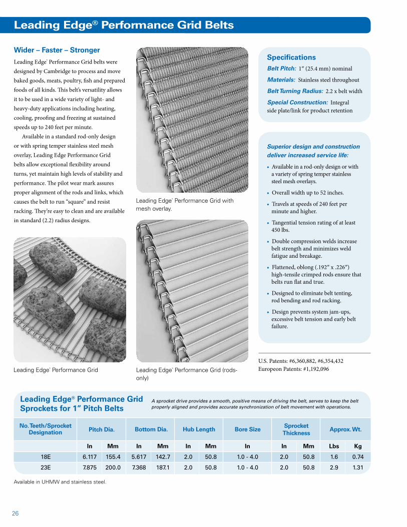
Leading Edge® Performance Grid Belts
Leading Edge® Performance Grid with mesh overlay.
Wider – Faster – Stronger
Leading Edge® Performance Grid belts were designed by Cambridge to process and move baked goods, meats, poultry, fish and prepared foods of all kinds. This belt’s versatility allows it to be used in a wide variety of light- and heavy-duty applications including heating, cooling, proofing and freezing at sustained speeds up to 240 feet per minute.
Available in a standard rod-only design or with spring temper stainless steel mesh overlay, Leading Edge Performance Grid belts allow exceptional flexibility around turns, yet maintain high levels of stability and performance. The pilot wear mark assures proper alignment of the rods and links, which causes the belt to run “square” and resist racking. They’re easy to clean and are available in standard (2.2) radius designs.
Superior design and construction deliver increased service life:
• Available in a rod-only design or with a variety of spring temper stainless steel mesh overlays.
• Overall width up to 52 inches.
• Travels at speeds of 240 feet per minute and higher.
• Tangential tension rating of at least 450 lbs.
• Double compression welds increase belt strength and minimizes weld fatigue and breakage.
• Flattened, oblong (.192″ x .226″) high-tensile crimped rods ensure that belts run flat and true.
• Designed to eliminate belt tenting, rod bending and rod racking.
• Design prevents system jam-ups, excessive belt tension and early belt failure.
U.S. Patents: #6,360,882, #6,354,432Europeon Patents: #1,192,096Leading Edge® Performance Grid
A sprocket drive provides a smooth, positive means of driving the belt, serves to keep the belt properly aligned and provides accurate synchronization of belt movement with operations.
Leading Edge® Performance Grid Sprockets for 1” Pitch Belts
No. Teeth/Sprocket Designation Pitch Dia. Bottom Dia. Hub Length Bore Size
Sprocket Thickness
Approx. Wt.
In Mm In Mm In Mm In In Mm Lbs Kg
18E 6.117 155.4 5.617 142.7 2.0 50.8 1.0 - 4.0 2.0 50.8 1.6 0.74
23E 7.875 200.0 7.368 187.1 2.0 50.8 1.0 - 4.0 2.0 50.8 2.9 1.31
Available in UHMW and stainless steel.
SpecificationsBelt Pitch: 1″ (25.4 mm) nominal
Materials: Stainless steel throughout
Belt Turning Radius: 2.2 x belt width
Special Construction: Integral side plate/link for product retention
Leading Edge® Performance Grid (rods-only)
27
A sprocket drive provides a smooth, positive means of driving the belt, serves to keep the belt properly aligned and provides accurate synchronization of belt movement with operations. Cam-Grid® Xtra Sprockets
No. Teeth/Sprocket Designation Pitch Dia. Bottom Dia. Hub Length Bore Size
Sprocket Thickness
Approx. Wt.
In Mm In Mm In Mm In In Mm Lbs Kg
13-1.5E 6.44 163.65 5.63 143.03 7.68 179.53 1.0 - 4.0 2.0 50.9 1.6 0.73
18-1.5E 8.88 225.55 8.13 206.50 9.51 241.43 1.0 - 4.0 2.0 50.9 2.9 1.32
Sprockets are available in UHMW and stainless steel.
Cam-Grid® Xtra Spiral System Belting
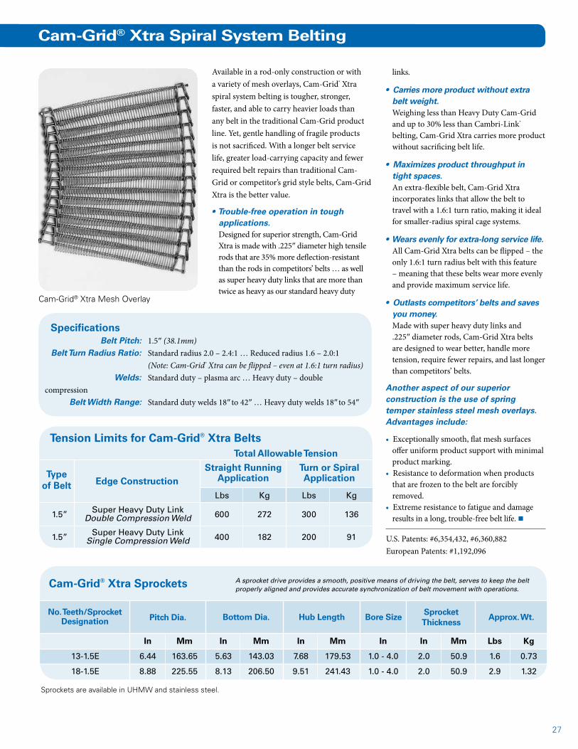
Available in a rod-only construction or with a variety of mesh overlays, Cam-Grid® Xtra spiral system belting is tougher, stronger, faster, and able to carry heavier loads than any belt in the traditional Cam-Grid product line. Yet, gentle handling of fragile products is not sacrificed. With a longer belt service life, greater load-carrying capacity and fewer required belt repairs than traditional Cam-Grid or competitor’s grid style belts, Cam-Grid Xtra is the better value.
• Trouble-free operation in tough applications.Designed for superior strength, Cam-Grid Xtra is made with .225″ diameter high tensile rods that are 35% more deflection-resistant than the rods in competitors’ belts … as well as super heavy duty links that are more than twice as heavy as our standard heavy duty
Cam-Grid® Xtra Mesh Overlay
Specifications Belt Pitch: 1.5″ (38.1mm) Belt Turn Radius Ratio: Standard radius 2.0 – 2.4:1 … Reduced radius 1.6 – 2.0:1 (Note: Cam-Grid® Xtra can be flipped – even at 1.6:1 turn radius) Welds: Standard duty – plasma arc … Heavy duty – double compression Belt Width Range: Standard duty welds 18″ to 42″ … Heavy duty welds 18″ to 54″
U.S. Patents: #6,354,432, #6,360,882European Patents: #1,192,096
Tension Limits for Cam-Grid® Xtra Belts
Type of Belt
Straight Running Application
Turn or Spiral ApplicationEdge Construction
Total Allowable Tension
links.
• Carries more product without extra belt weight.Weighing less than Heavy Duty Cam-Grid and up to 30% less than Cambri-Link® belting, Cam-Grid Xtra carries more product without sacrificing belt life.
• Maximizes product throughput in tight spaces.An extra-flexible belt, Cam-Grid Xtra incorporates links that allow the belt to travel with a 1.6:1 turn ratio, making it ideal for smaller-radius spiral cage systems.
• Wears evenly for extra-long service life.All Cam-Grid Xtra belts can be flipped – the only 1.6:1 turn radius belt with this feature – meaning that these belts wear more evenly and provide maximum service life.
• Outlasts competitors’ belts and saves you money.Made with super heavy duty links and .225″ diameter rods, Cam-Grid Xtra belts are designed to wear better, handle more tension, require fewer repairs, and last longer than competitors’ belts.
Another aspect of our superior construction is the use of spring temper stainless steel mesh overlays. Advantages include:
• Exceptionally smooth, flat mesh surfaces offer uniform product support with minimal product marking.
• Resistance to deformation when products that are frozen to the belt are forcibly removed.
• Extreme resistance to fatigue and damage results in a long, trouble-free belt life. n
Lbs Kg Lbs Kg
1.5” Super Heavy Duty Link 600 272 300 136 Double Compression Weld
1.5” Super Heavy Duty Link 400 182 200 91 Single Compression Weld

28
Cambri-Link® Belts
Tension Limits for Standard and Reduced Radius Cambri-Link® Belts
Double Bars One Side Double Bars Both Sides
Lbs/Ft Kg/M Lbs Kg
1/2”x1” MESH Extra Heavy Duty 1,700 2,530 400 136.1
1”X1” MESH Extra Heavy Duty 1,350 2,009 400 136.1
Type of Belt
Straight Running Application
Turn or Spiral ApplicationDouble
Reinforcement Edge Construction
Cambri-Link® 1” x 1” Standard Radius
Cambri-Link® turn belts offer processors the advantages of a rugged flat wire style of belt for spiral system applications. Designed for multi-tier spiral conveyor systems used in the food industry, they are also ideal for many other applications requiring right- and left-turn capabilities, such as in conveying around obstacles or in limited space, and eliminating transfers.
Cambri-Link spiral system belts are available in standard (2.2) radius … reduced (1.7 or 1.5) radius … and tight (1.0) radius
Efficient and economical, these belts provide many outstanding benefits:
• Large open-mesh area for air circulation and drainage.
• High strength-to-weight ratio for increased capacity.
• Collapsibility for quick and easy cleaning.
• Minimum maintenance for low operating costs.
• Long service life for maximum return on investment.
• Flat surface for excellent product stability.
• Smooth, vibration-free operation in straight or turn configurations.
designs. Contact us for other radius options. Cambri-Link belts are offered with single or double reinforcing bars. Various combinations of reinforcing bars can be configured to achieve added tension capabilities.
Reduced Radius BeltsCambri-Link Reduced Radius belts are
Extended bar side plate for product retention.
Offset lane divider to separate or contain product.
available with a minimum inside radius of 1.7 or 1.5 times the belt width. These belts require no central links or bars to interfere with product placement. Both are ideal for freezing, cooling and proofing applications. They allow bakery products, meat, fish, poultry or packaged specialty products to be processed with space-saving efficiency.
Cambri-Link® 1/2” x 1”
Cambri-Link® 1” x 1” with double bars.
29
Standard and Reduced Radius Belt Specifications
Belt Pitch: 1″ (25.4mm)
Mesh Sizes: 1/2″ x 1″ or 1″ x 1″
Belt Width Range: 12″ to 48″ (305mm to 1,219mm) overall, standard … other widths also available
Materials: Wear-resistant stainless steel (WRSS) is standard. Other materials available including T-304, T-316 and HCS.
Special Constructions: Side plates and lane dividers available
Lbs/Ft Kg/M Lbs Kg
1/2” x 1” / 1/2” x 1-1/2” Extra Heavy Duty 850 1,265 400 136.1
1” x 1” / 1/2” x 1-1/2” Extra Heavy Duty 675 1,005 400 136.1
1” x 1” / 1” x 1-1/2” Extra Heavy Duty 675 1,005 400 136.1
Tension Limits for Tight Radius Cambri-Link® Belts
Type of Belt
Straight Running Application
Turn or Spiral ApplicationDouble
Reinforcement Edge Construction
Total allowable tension
Tension per unit of belt width
* Note: All other specifications are the same as noted for Cambri-Link® standard radius belts.
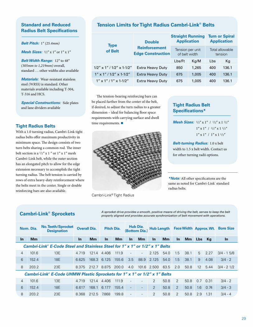
Cambri-Link® Tight Radius
Tight Radius BeltsWith a 1.0 turning radius, Cambri-Link tight radius belts offer maximum productivity in minimum space. The design consists of two turn belts sharing a common rod. The inner belt section is a 1/2″ x 1 ″ or 1″ x 1″ mesh Cambri-Link belt, while the outer section has an elongated pitch to allow for the edge extension necessary to accomplish the tight turning radius. The belt tension is carried by rows of extra heavy-duty reinforcement where the belts meet in the center. Single or double reinforcing bars are also available.
Tight Radius Belt Specifications*
Mesh Sizes: 1/2″ x 1″ / 1/2″ x 1 1/2″
1″ x 1″ / 1/2″ x 1 1/2″
1″ x 1″ / 1″ x 1 1/2″
Belt-turning Radius: 1.0 x belt width to 1.5 x belt width. Contact us for other turning radii options.
The tension-bearing reinforcing bars can be placed further from the center of the belt, if desired, to adjust the turn radius to a greater dimension – ideal for balancing floor space requirements with carrying surface and dwell time requirements. n
A sprocket drive provides a smooth, positive means of driving the belt, serves to keep the belt properly aligned and provides accurate synchronization of belt movement with operations. Cambri-Link® Sprockets
Nom. Dia. No. Teeth/Sprocket Designation
Overall Dia. Pitch Dia. Hub Dia. (Bottom Dia.)
Hub Length Face Width Approx. Wt. Bore Size
In Mm In Mm In Mm In Mm In Mm In Mm Lbs Kg In
Cambri-Link® E-Code Steel and Stainless Steel for 1” x 1” or 1/2” x 1” Belts
4 101.6 13E 4.719 121.4 4.406 111.9 - - 2.125 54.0 1.5 38.1 5 2.27 3/4 - 1 5/8
6 152.4 18E 6.625 168.3 6.125 155.6 3.5 88.9 2.125 54.0 1.5 38.1 9 4.08 3/4 - 2
8 203.2 23E 8.375 212.7 8.875 200.0 4.0 101.6 2.500 63.5 2.0 50.8 12 5.44 3/4 - 2 1/2
Cambri-Link® E-Code UHMW Plastic Sprockets for 1” x 1” or 1/2” x 1” Belts
4 101.6 13E 4.719 121.4 4.406 111.9 - - 2 50.8 2 50.8 0.7 0.31 3/4 - 2
6 152.4 18E 6.617 168.1 6.177 155.4 - - 2 50.8 2 50.8 1.6 0.74 3/4 - 3
8 203.2 23E 8.368 212.5 7.868 199.8 - - 2 50.8 2 50.8 2.9 1.31 3/4 - 4
30
Cam-Grid® Belts
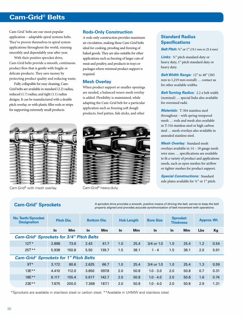
Cam-Grid® with mesh overlay.
Cam-Grid® belts are our most popular application – adaptable spiral systems belts. They’ve proven themselves in spiral system applications throughout the world, running smoothly and dependably year after year.
With their positive sprocket drive, Cam-Grid belts provide a smooth, continuous product flow that is gentle with fragile or delicate products. They save money by protecting product quality and reducing waste.
Fully collapsible for easy cleaning, Cam-Grid belts are available in standard (2.2) radius, reduced (1.7) radius, and tight (1.1) radius designs. It can be manufactured with a double pitch overlay, or with plastic filler rods or strips for supporting extremely small products.
Standard Radius Specifications
Belt Pitch: ¾″ or 1″ (19.1 mm or 25.4 mm)
Links: ¾″ pitch standard duty or heavy duty, 1″ pitch standard duty or heavy duty.
Belt Width Range: 12″ to 48″ (305 mm to 1,219 mm overall) … contact us for other available widths.
Belt Turning Radius: 2.2 x belt width (nominal) … special links also available for oversized radii.
Materials: T-304 stainless steel throughout – with spring-tempered mesh … rods and mesh also available in T-316 stainless steel or high carbon steel … mesh overlays also available in annealed stainless steel.
Mesh Overlay: Standard mesh overlays available in 14 – 18 gauge mesh wire sizes … specifications are available to fit a variety of product and applications needs, such as open meshes for airflow or tighter meshes for product support.
Special Constructions: Standard side plates available for ¾″ or 1″ pitch.
Cam-Grid® heavy-duty.
Rods-Only ConstructionA rods-only construction provides maximum air circulation, making these Cam-Grid belts ideal for cooking, proofing and freezing of baked goods. They are also suitable for other applications such as freezing of larger cuts of meat and poultry, and products in trays or packages where minimal product support is required.
Mesh OverlayWhen product support or smaller openings are needed, a balanced weave mesh overlay is added. Flexibility is maintained, while adapting the Cam-Grid belt for a particular application such as freezing soft dough products, beef patties, fish sticks, and other
A sprocket drive provides a smooth, positive means of driving the belt, serves to keep the belt properly aligned and provides accurate synchronization of belt movement with operations.
Cam-Grid® Sprockets
No. Teeth/Sprocket Designation Pitch Dia. Bottom Dia. Hub Length Bore Size
Sprocket Thickness
*Sprockets are available in stainless steel or carbon steel. **Available in UHMW and stainless steel.
In Mm In Mm In Mm In In Mm Lbs Kg
Cam-Grid® Sprockets for 3/4” Pitch Belts 12T * 2.898 73.6 2.43 61.7 1.0 25.4 3/4 or 1.0 1.0 25.4 1.2 0.54
25T ** 5.938 150.8 5.50 139.7 1.5 38.1 1 - 4 1.5 38.1 2.0 0.91
Cam-Grid® Sprockets for 1” Pitch Belts 9T* 3.172 80.6 2.625 66.7 1.0 25.4 3/4 or 1.0 1.0 25.4 1.3 0.59
13E** 4.410 112.0 3.850 097.8 2.0 50.8 1.0 - 3.0 2.0 50.8 0.7 0.31
18E** 6.117 155.4 5.617 142.7 2.0 50.8 1.0 - 4.0 2.0 50.8 1.6 0.74
23E** 7.875 200.0 7.368 187.1 2.0 50.8 1.0 - 4.0 2.0 50.8 2.9 1.31
Approx. Wt.
31
Tension Limits for Cam-Grid® Belts
Lbs Kg Lbs Kg
Standard Duty Link 200 90.7 100 45.4
3/4” Heavy Duty Link (a) 200 90.7 150 68.1
1” Heavy Duty Link 300 136.1 150 68.1
Type of Belt
Straight Running Application
Turn or Spiral ApplicationEdge Construction
Total Allowable Tension
3/4” Pitchor
1” Pitch
Reduced Radius
(a) 3/4” Heavy Duty link is non-collapsing and is used only on outside edge.(b) Heavy Duty Links are located in the center load-bearing section of the belt, not on the outer edge.
Standard Duty Link 200 90.7 100 45.4
Heavy Duty Link 200 90.7 150 68.11” Pitch
Tight Radius
Heavy Duty Link (b) 200 90.7 150 68.13/4”Pitch
Standard Radius
* Note: Except as noted, all other specifications are the same as for Cam-Grid® standard radius belts.
Tight Radius Specifications*
Belt Pitch: ¾″ (19.1 mm)
Belt Width Range: 12″ to 48″ (305 mm x 1,219 mm) … wider widths available depending on application.
Belt Turning Radius: 1.1 to 1.7 x belt width (nominal inside turning radius when tension-bearing links are located in the center of the belt). Contact us for applications involving other turn radii.
Drive Sprockets: Located on the belt’s inner and center links only.
Special Constructions: Integral side plate/links available for outer belt edge only.
Reduced Radius Specifications*
Belt Pitch: 1″ (25.4 mm) nominal
Belt Turning Radius: 1.7 to 2.2 x belt width (nominal inside turning radius)
Special Constructions: Integral side plates/links available for product retention.
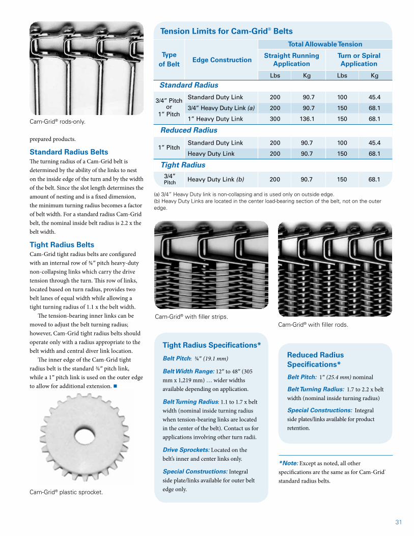
Cam-Grid® rods-only.
Cam-Grid® plastic sprocket.
prepared products.
Standard Radius BeltsThe turning radius of a Cam-Grid belt is determined by the ability of the links to nest on the inside edge of the turn and by the width of the belt. Since the slot length determines the amount of nesting and is a fixed dimension, the minimum turning radius becomes a factor of belt width. For a standard radius Cam-Grid belt, the nominal inside belt radius is 2.2 x the belt width.
Tight Radius BeltsCam-Grid tight radius belts are configured with an internal row of ¾″ pitch heavy-duty non-collapsing links which carry the drive tension through the turn. This row of links, located based on turn radius, provides two belt lanes of equal width while allowing a tight turning radius of 1.1 x the belt width.
The tension-bearing inner links can be moved to adjust the belt turning radius; however, Cam-Grid tight radius belts should operate only with a radius appropriate to the belt width and central diver link location.
The inner edge of the Cam-Grid tight radius belt is the standard ¾″ pitch link, while a 1″ pitch link is used on the outer edge to allow for additional extension. n
Cam-Grid® with filler strips.Cam-Grid® with filler rods.
32
Heavy Duty Tight Radius Cam-Grid Sprockets
No. of Teeth/Designation PitchDiameter
Hub Diameter(Bottom Diameter)
Bore Size
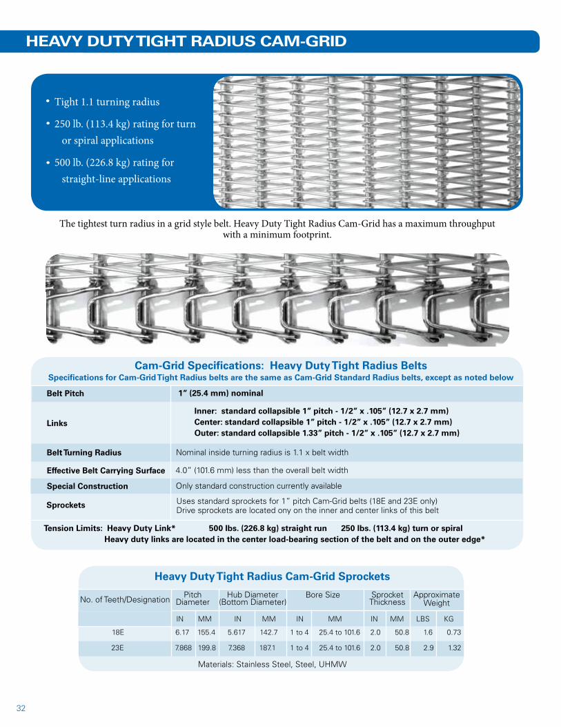
Tight 1.1 turning radius
250 lb. (113.4 kg) rating for turn or spiral applications
500 lb. (226.8 kg) rating for straight-line applications
The tightest turn radius in a grid style belt. Heavy Duty Tight Radius Cam-Grid has a maximum throughput with a minimum footprint.
HEAVY DUTY TIGHT RADIUS CAM-GRID
Cam-Grid Specifications: Heavy Duty Tight Radius BeltsSpecifications for Cam-Grid Tight Radius belts are the same as Cam-Grid Standard Radius belts, except as noted below
Belt Pitch 1” (25.4 mm) nominal
Links
Inner: standard collapsible 1” pitch - 1/2” x .105” (12.7 x 2.7 mm)Center: standard collapsible 1” pitch - 1/2” x .105” (12.7 x 2.7 mm)Outer: standard collapsible 1.33” pitch - 1/2” x .105” (12.7 x 2.7 mm)
Belt Turning Radius Nominal inside turning radius is 1.1 x belt width
Effective Belt Carrying Surface
Tension Limits: Heavy Duty Link* 500 lbs. (226.8 kg) straight run 250 lbs. (113.4 kg) turn or spiral Heavy duty links are located in the center load-bearing section of the belt and on the outer edge*
4.0” (101.6 mm) less than the overall belt width
Special Construction Only standard construction currently available
Sprockets Uses standard sprockets for 1” pitch Cam-Grid belts (18E and 23E only)Drive sprockets are located ony on the inner and center links of this belt
SprocketThickness
ApproximateWeight
Materials: Stainless Steel, Steel, UHMW
18E 6.17 155.4 5.617 142.7 1 to 4 25.4 to 101.6 2.0 50.8 1.6 0.73
23E 7.868 199.8 7.368 187.1 1 to 4 25.4 to 101.6 2.0 50.8 2.9 1.32
IN MM IN MM IN MM IN MM LBS KG
33
Inner: standard collapsible 1” pitch - 1/2” x .105” (12.7 x 2.7 mm)Center: standard collapsible 1” pitch - 1/2” x .105” (12.7 x 2.7 mm)Outer: standard collapsible 1.33” pitch - 1/2” x .105” (12.7 x 2.7 mm)
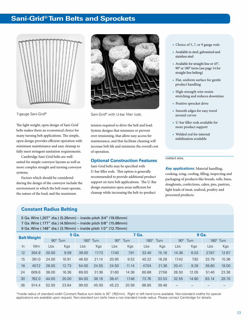
Sani-Grid® Turn Belts and Sprockets
The light weight, open design of Sani-Grid® belts makes them an economical choice for many turning belt applications. The simple, open design provides efficient operation with minimum maintenance and easy cleanup to fully meet stringent sanitation requirements.
Cambridge Sani-Grid belts are well-suited for simple conveyor layouts as well as more complex straight and turning conveyor systems.
Factors which should be considered during the design of the conveyor include the environment in which the belt must operate, the nature of the load, and the maximum
7-gauge Sani-Grid®
Constant Radius Belting
5 Ga. Wire (.207” dia.) (5.26mm) – inside pitch 3/4” (19.05mm)7 Ga. Wire (.177” dia.) (4.50mm) – inside pitch 5/8” (15.88mm)9 Ga. Wire (.148” dia.) (3.76mm) – inside pitch 1/2” (12.70mm)
Belt Weight5 Ga. 7 Ga. 9 Ga.
90° Turn 180° Turn 90° Turn 180° Turn 90° Turn 180° Turn
In Mm Lbs Kgs Lbs Kgs Lbs Kgs Lbs Kgs Lbs Kgs Lbs Kgs
12 304.8 20.00 9.09 39.00 17.73 17.40 7.91 33.40 15.18 14.36 6.53 27.87 12.67
15 381.0 24.00 10.91 46.50 21.14 20.95 9.52 40.22 18.28 17.42 7.92 33.79 15.36
18 457.2 28.00 12.73 54.00 24.55 24.50 11.14 47.04 21.38 20.41 9.28 39.60 18.00
24 609.6 36.00 16.36 69.00 31.36 31.60 14.36 60.68 27.58 26.50 12.05 51.40 23.36
30 762.0 44.00 20.00 84.00 38.18 38.41 17.46 73.76 33.53 32.55 14.80 63.14 28.70
36 914.4 52.00 23.64 99.00 45.00 45.23 20.56 86.85 39.48 – – – –
*Inside radius of standard width Constant Radius turn belts is 30” (762mm). Right or left hand turns available. Non-standard widths for special applications are available upon request. Non-standard turn belts have a non-standard inside radius. Please contact Cambridge for details.
• Choice of 5, 7, or 9 gauge rods
• Available in steel, galvanized and stainless steel
• Available for straight line or 45°, 90° or 180° turns (see page 14 for straight line belting)
• Flat, uniform surface for gentle product handling
• High-strength wire resists stretching and reduces downtime
• Positive sprocket drive
• Smooth edges for easy travel around curves
• U-bar filler rods available for more product support
• Welded rod for internal stabilization available
tension required to drive the belt and load. System designs that minimize or prevent over-tensioning, that allow easy access for maintenance, and that facilitate cleaning will increase belt life and minimize the overall cost of operation.
Optional Construction FeaturesSani-Grid belts may be specified with U-bar filler rods. This option is generally recommended to provide additional product support on turn belt applications. The U-Bar design maintains open areas sufficient for cleanup while increasing the belt-to-product
contact area.
Key applications: Material handling, cooking, icing, cooling, filling, inspecting and packaging of products like breads, rolls, buns, doughnuts, confections, cakes, pies, pastries, light loads of meat, seafood, poultry and processed products.
Sani-Grid® with U-bar filler rods.

34
In Mm In Mm In Mm Lbs Kg
5TC12* 12 304.8 9 2.986 75.8 3.247 82.5 0.11 0.05
5TC18* 18 457.2 9 3.419 86.8 3.680 93.5 0.15 0.07
5TC24* 24 609.2 9 3.852 97.8 4.113 104.5 0.21 0.10
5TC30* 30 762.0 9 4.284 108.8 4.545 115.4 0.26 0.12
5TC36* 36 914.4 9 4.721 119.9 4.982 126.5 0.33 0.15
7TC12* 12 304.8 11 3.031 77.0 3.324 84.4 0.11 0.05
7TC15* 15 381.0 11 3.250 82.6 3.543 90.0 0.14 0.06
7TC18* 18 457.2 11 3.472 88.2 3.765 95.6 0.16 0.07
7TC24* 24 609.2 11 3.908 99.3 4.201 106.7 0.21 0.10
7TC30* 30 762.0 11 4.348 110.4 4.641 117.9 0.27 0.12
7TC36* 36 914.4 11 4.785 121.5 5.078 129.0 0.34 0.15
7TC42* 42 1066.8 11 5.213 132.4 5.506 139.9 0.41 0.19
9TC12 12 304.8 11 2.435 61.9 2.677 68.0 1.05 0.48
9TC15 15 381.0 11 2.609 66.3 2.851 72.4 1.28 0.58
9TC18 18 457.2 11 2.785 70.7 3.027 76.9 1.48 0.67
9TC24 24 609.2 11 3.136 79.7 3.378 85.8 1.87 0.85
9TC30 30 762.0 11 3.487 88.6 3.729 94.7 2.53 1.15
Sani-Grid® Outside Sprockets for Constant Radius Turn Belts
Belt Type
5 Gauge .207” 5.26Mm
7 Gauge .177” 4.50Mm
9 Gauge .148” 3.76Mm
All sprockets available in T-303 stainless steel. *Two-piece sprockets, with UHMWPE outer ring and stainless steel hubset. Assembly hardware included. Sprockets supplied with 3/4” or 1” bore, standard keyway, and set screw. Larger bore sizes available upon request.
Sprocket No.
For Belt Width No. of Teeth
Pitch Dia. Outside Dia. Approx. Wt.
A sprocket drive provides a smooth, positive means of driving the belt, serves to keep the belt properly aligned and provides accurate synchronization of belt movement with operations.
5 Gauge .207” 5.26Mm
7 Gauge .177” 4.50Mm
9 Gauge .148” 3.76Mm
5TCI* – – 9 2.210 56.1 2.471 62.8 0.11 0.05
7TCI* – – 11 2.218 56.3 2.511 63.8 0.10 0.05
9TCI* – – 11 1.780 45.2 2.068 52.5 0.52 0.24
Sani-Grid® Inside Sprockets for Constant Radius Turn Belts
Sani-Grid® Sprockets
Sani-Grid® SprocketsWe supply metal and plastic sprockets for use with Sani-Grid constant-radius turn belts. It is important that the outside sprocket be selected for the particular belt width being used.
UHMWPE Sani-Grid sprockets were developed specifically for 5- and 7- gauge Sani-Grid belting. Outside sprockets for constant radius turn Sani-Grid belts are offered in a two piece design, with stainless steel hubs and screws, and UHMWPE outer sprocket rings. This allows for reuse of the hub and replacement of only the outer sprocket rings as necessary.
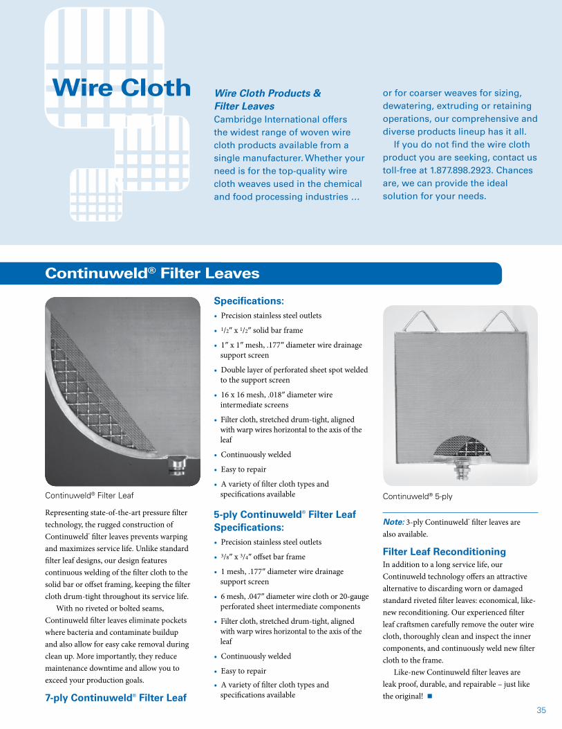
35
Note: 3-ply Continuweld® filter leaves are also available.
Filter Leaf ReconditioningIn addition to a long service life, our Continuweld technology offers an attractive alternative to discarding worn or damaged standard riveted filter leaves: economical, like-new reconditioning. Our experienced filter leaf craftsmen carefully remove the outer wire cloth, thoroughly clean and inspect the inner components, and continuously weld new filter cloth to the frame.
Like-new Continuweld filter leaves are leak proof, durable, and repairable – just like the original! n
Wire Cloth Wire Cloth Products & Filter LeavesCambridge International offers the widest range of woven wire cloth products available from a single manufacturer. Whether your need is for the top-quality wire cloth weaves used in the chemical and food processing industries …
or for coarser weaves for sizing, dewatering, extruding or retaining operations, our comprehensive and diverse products lineup has it all.
If you do not find the wire cloth product you are seeking, contact us toll-free at 1.877.898.2923. Chances are, we can provide the ideal solution for your needs.
Continuweld® Filter Leaves
Representing state-of-the-art pressure filter technology, the rugged construction of Continuweld® filter leaves prevents warping and maximizes service life. Unlike standard filter leaf designs, our design features continuous welding of the filter cloth to the solid bar or offset framing, keeping the filter cloth drum-tight throughout its service life.
With no riveted or bolted seams, Continuweld filter leaves eliminate pockets where bacteria and contaminate buildup and also allow for easy cake removal during clean up. More importantly, they reduce maintenance downtime and allow you to exceed your production goals.
7-ply Continuweld® Filter Leaf
Specifications:• Precision stainless steel outlets
• 1/2″ x 1/2″ solid bar frame
• 1″ x 1″ mesh, .177″ diameter wire drainage support screen
• Double layer of perforated sheet spot welded to the support screen
• 16 x 16 mesh, .018″ diameter wire intermediate screens
• Filter cloth, stretched drum-tight, aligned with warp wires horizontal to the axis of the leaf
• Continuously welded
• Easy to repair
• A variety of filter cloth types and specifications available
5-ply Continuweld® Filter Leaf Specifications:• Precision stainless steel outlets
• 3/8″ x 3/4″ offset bar frame
• 1 mesh, .177″ diameter wire drainage support screen
• 6 mesh, .047″ diameter wire cloth or 20-gauge perforated sheet intermediate components
• Filter cloth, stretched drum-tight, aligned with warp wires horizontal to the axis of the leaf
• Continuously welded
• Easy to repair
• A variety of filter cloth types and specifications available
Continuweld® 5-plyContinuweld® Filter Leaf
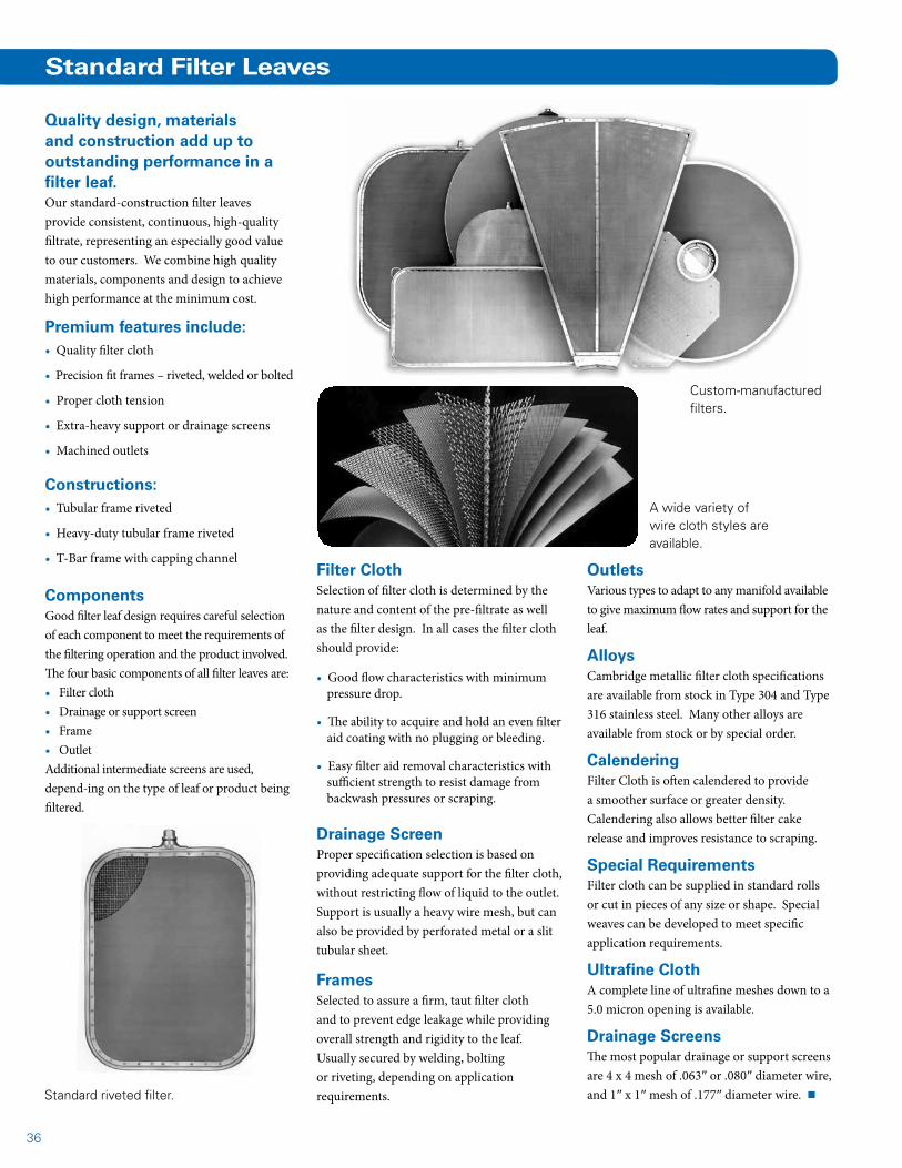
36
Standard Filter Leaves
Standard riveted filter.
A wide variety of wire cloth styles are available.
Custom-manufactured filters.
Quality design, materials and construction add up to outstanding performance in a filter leaf.Our standard-construction filter leaves provide consistent, continuous, high-quality filtrate, representing an especially good value to our customers. We combine high quality materials, components and design to achieve high performance at the minimum cost.
Premium features include:• Quality filter cloth
• Precision fit frames – riveted, welded or bolted
• Proper cloth tension
• Extra-heavy support or drainage screens
• Machined outlets
Constructions: • Tubular frame riveted
• Heavy-duty tubular frame riveted
• T-Bar frame with capping channel
ComponentsGood filter leaf design requires careful selection of each component to meet the requirements of the filtering operation and the product involved. The four basic components of all filter leaves are: • Filter cloth • Drainage or support screen • Frame • Outlet Additional intermediate screens are used, depend-ing on the type of leaf or product being filtered.
Filter ClothSelection of filter cloth is determined by the nature and content of the pre-filtrate as well as the filter design. In all cases the filter cloth should provide:
• Good flow characteristics with minimum pressure drop.
• The ability to acquire and hold an even filter aid coating with no plugging or bleeding.
• Easy filter aid removal characteristics with sufficient strength to resist damage from backwash pressures or scraping.
Drainage ScreenProper specification selection is based on providing adequate support for the filter cloth, without restricting flow of liquid to the outlet. Support is usually a heavy wire mesh, but can also be provided by perforated metal or a slit tubular sheet.
FramesSelected to assure a firm, taut filter cloth and to prevent edge leakage while providing overall strength and rigidity to the leaf. Usually secured by welding, bolting or riveting, depending on application requirements.
OutletsVarious types to adapt to any manifold available to give maximum flow rates and support for the leaf.
AlloysCambridge metallic filter cloth specifications are available from stock in Type 304 and Type 316 stainless steel. Many other alloys are available from stock or by special order.
CalenderingFilter Cloth is often calendered to provide a smoother surface or greater density. Calendering also allows better filter cake release and improves resistance to scraping.
Special RequirementsFilter cloth can be supplied in standard rolls or cut in pieces of any size or shape. Special weaves can be developed to meet specific application requirements.
Ultrafine ClothA complete line of ultrafine meshes down to a 5.0 micron opening is available.
Drainage ScreensThe most popular drainage or support screens are 4 x 4 mesh of .063″ or .080″ diameter wire, and 1″ x 1″ mesh of .177″ diameter wire. n
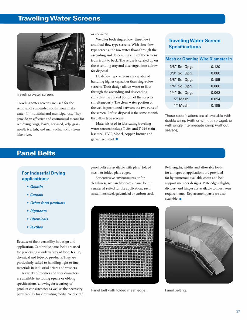
37
These specifications are all available with double crimp (with or without selvage), or with single intermediate crimp (without selvage).
Traveling Water Screen Specifications
Mesh or Opening Wire Diameter In
3/8” Sq. Opg. 0.120
3/8” Sq. Opg. 0.080
3/8” Sq. Opg. 0.105
1/4” Sq. Opg. 0.080
1/4” Sq. Opg. 0.063
5” Mesh 0.054
1” Mesh 0.105
Traveling Water Screens
Traveling water screens are used for the removal of suspended solids from intake water for industrial and municipal use. They provide an effective and economical means for removing twigs, leaves, seaweed, kelp, grass, needle ice, fish, and many other solids from lake, river,
or seawater. We offer both single-flow (thru-flow)
and dual-flow type screens. With thru-flow type screens, the raw water flows through the ascending and descending runs of the screens from front to back. The refuse is carried up on the ascending tray and discharged into a draw for disposal.
Dual-flow type screens are capable of handling higher capacities than single-flow screens. Their design allows water to flow through the ascending and descending runs plus the curved bottom of the screens simultaneously. The clean water portion of the well is positioned between the two runs of the screen. Refuse disposal is the same as with thru-flow type screens.
Materials used in fabricating traveling water screens include T-304 and T-316 stain-less steel, PVC, Monel, copper, bronze and galvanized steel. n
Traveling water screen.
Panel Belts
Because of their versatility in design and application, Cambridge panel belts are used for processing a wide variety of food, textile, chemical and tobacco products. They are particularly suited to handling light or fine materials in industrial driers and washers.
A variety of meshes and wire diameters are available, including square or oblong specifications, allowing for a variety of product consistencies as well as the necessary permeability for circulating media. Wire cloth
Panel belting.Panel belt with folded mesh edge.
panel belts are available with plain, folded mesh, or folded plate edges.
For corrosive environments or for cleanliness, we can fabricate a panel belt in a material suited for the application, such as stainless steel, galvanized or carbon steel.
Belt lengths, widths and allowable loads for all types of applications are provided for by numerous available chain and belt support member designs. Plate edges, flights, dividers and hinges are available to meet your requirements. Replacement parts are also available. n
For Industrial Drying applications:
• Gelatin
• Cereals
• Other food products
• Pigments
• Chemicals
• Textiles
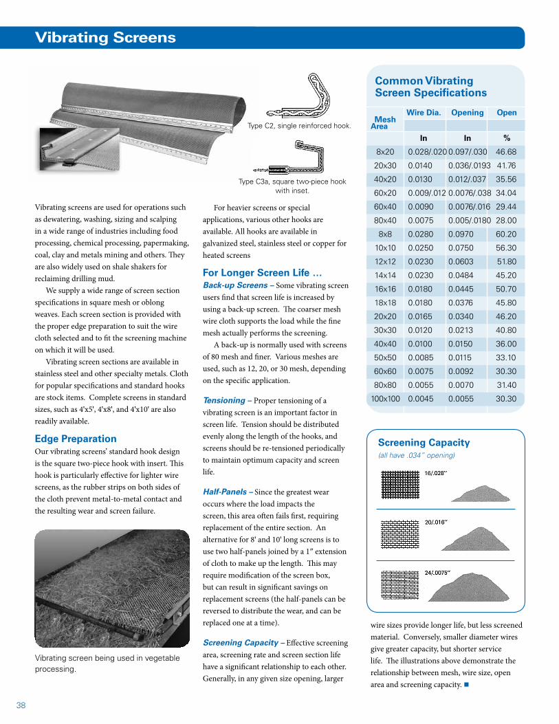
38
Common Vibrating Screen Specifications
Mesh
Vibrating screens are used for operations such as dewatering, washing, sizing and scalping in a wide range of industries including food processing, chemical processing, papermaking, coal, clay and metals mining and others. They are also widely used on shale shakers for reclaiming drilling mud.
We supply a wide range of screen section specifications in square mesh or oblong weaves. Each screen section is provided with the proper edge preparation to suit the wire cloth selected and to fit the screening machine on which it will be used.
Vibrating screen sections are available in stainless steel and other specialty metals. Cloth for popular specifications and standard hooks are stock items. Complete screens in standard sizes, such as 4'x5', 4'x8', and 4'x10' are also readily available.
Edge PreparationOur vibrating screens’ standard hook design is the square two-piece hook with insert. This hook is particularly effective for lighter wire screens, as the rubber strips on both sides of the cloth prevent metal-to-metal contact and the resulting wear and screen failure.
Vibrating Screens
For heavier screens or special applications, various other hooks are available. All hooks are available in galvanized steel, stainless steel or copper for heated screens
For Longer Screen Life …Back-up Screens – Some vibrating screen users find that screen life is increased by using a back-up screen. The coarser mesh wire cloth supports the load while the fine mesh actually performs the screening.
A back-up is normally used with screens of 80 mesh and finer. Various meshes are used, such as 12, 20, or 30 mesh, depending on the specific application.
Tensioning – Proper tensioning of a vibrating screen is an important factor in screen life. Tension should be distributed evenly along the length of the hooks, and screens should be re-tensioned periodically to maintain optimum capacity and screen life.
Half-Panels – Since the greatest wear occurs where the load impacts the screen, this area often fails first, requiring replacement of the entire section. An alternative for 8' and 10' long screens is to use two half-panels joined by a 1″ extension of cloth to make up the length. This may require modification of the screen box, but can result in significant savings on replacement screens (the half-panels can be reversed to distribute the wear, and can be replaced one at a time).
Screening Capacity – Effective screening area, screening rate and screen section life have a significant relationship to each other. Generally, in any given size opening, larger
wire sizes provide longer life, but less screened material. Conversely, smaller diameter wires give greater capacity, but shorter service life. The illustrations above demonstrate the relationship between mesh, wire size, open area and screening capacity. n
Vibrating screen being used in vegetable processing.
Type C3a, square two-piece hook with inset.
Type C2, single reinforced hook.
Screening Capacity (all have .034” opening)
Wire Dia. Opening Open
Area In In %
8x20 0.028/.020 0.097/.030 46.68
20x30 0.0140 0.036/.0193 41.76
40x20 0.0130 0.012/.037 35.56
60x20 0.009/.012 0.0076/.038 34.04
60x40 0.0090 0.0076/.016 29.44
80x40 0.0075 0.005/.0180 28.00
8x8 0.0280 0.0970 60.20
10x10 0.0250 0.0750 56.30
12x12 0.0230 0.0603 51.80
14x14 0.0230 0.0484 45.20
16x16 0.0180 0.0445 50.70
18x18 0.0180 0.0376 45.80
20x20 0.0165 0.0340 46.20
30x30 0.0120 0.0213 40.80
40x40 0.0100 0.0150 36.00
50x50 0.0085 0.0115 33.10
60x60 0.0075 0.0092 30.30
80x80 0.0055 0.0070 31.40
100x100 0.0045 0.0055 30.30

39
Wire Cloth Fabrication
Wire cloth fabrication is one of the custom services we provide our clients. We can fabricate wire cloth parts of any size or shape – and in any metal or alloy – that are tailored to fit your process needs in new or replace- ment capacities. It’s an ideal resource for accurate, durable and efficient filtering, sizing, sifting, straining, heat treating and many other processes when standard parts are not available.
Our wire cloth fabrication department includes skilled craftsmen with years of experience, backed by extensive engineering and design facilities and precision manufac-turing equipment. Filter leaves, screens, baskets, strainers, trays and other special fabrications are available. Contact us at 1.877.898.2923 or [email protected] for more details. n
Raw Cloth
As one of the largest wire cloth manufacturers in the U.S. we offer industrial wire cloth in a complete range of specifications from 1
Plain or Double Crimped – A general-purpose
weave used most often for sizing and straining, or for
baskets and assemblies for
heat treating processes.
Twilled – Permits smaller openings and increased strength as a result of being able to use larger diameter wire.
Plain Dutch – A compact, firm cloth combin-ing great strength with very small openings. Openings are triangular and positioned at an angle rather than straight up, thereby providing faster and more even buildup of filter cake.
Twilled Double Dutch – Similar to Plain Dutch, but twilled weave permits compressing twice as many wires in the same area. The result is maximum density and smooth surface.
Oblong – One of several rectangular weaves that are used primarily for sizing aggregate and similar materials. It provides a greater open area than plain weave, resulting in far less blinding or clogging.
Lock Crimp – A securely fixed cloth features deep crimps in the wires at the point of inter-section lock the weave. This design of cloth is usually used for heavy-duty screening.
mesh to 500 mesh in various wire diameters. You may also choose from a wide variety of weaves, from ultrafine to the heaviest mesh. n
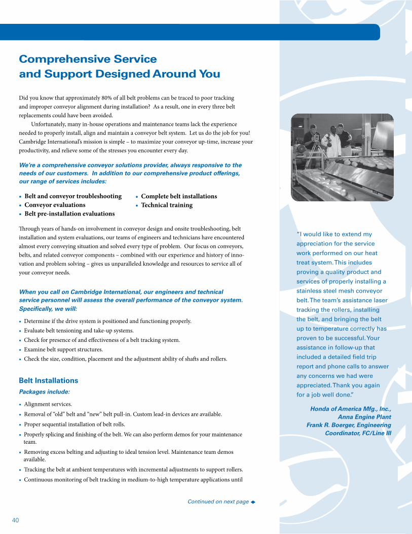
40
Did you know that approximately 80% of all belt problems can be traced to poor tracking and improper conveyor alignment during installation? As a result, one in every three belt replacements could have been avoided.
Unfortunately, many in-house operations and maintenance teams lack the experience needed to properly install, align and maintain a conveyor belt system. Let us do the job for you! Cambridge International’s mission is simple – to maximize your conveyor up-time, increase your productivity, and relieve some of the stresses you encounter every day.
We’re a comprehensive conveyor solutions provider, always responsive to the needs of our customers. In addition to our comprehensive product offerings, our range of services includes:
• Belt and conveyor troubleshooting• Conveyor evaluations• Belt pre-installation evaluations
Through years of hands-on involvement in conveyor design and onsite troubleshooting, belt installation and system evaluations, our teams of engineers and technicians have encountered almost every conveying situation and solved every type of problem. Our focus on conveyors, belts, and related conveyor components – combined with our experience and history of inno- vation and problem solving – gives us unparalleled knowledge and resources to service all of your conveyor needs.
When you call on Cambridge International, our engineers and technical service personnel will assess the overall performance of the conveyor system. Specifically, we will:
• Determine if the drive system is positioned and functioning properly.• Evaluate belt tensioning and take-up systems.• Check for presence of and effectiveness of a belt tracking system.• Examine belt support structures.• Check the size, condition, placement and the adjustment ability of shafts and rollers.
Belt InstallationsPackages include:
• Alignment services.
• Removal of “old” belt and “new” belt pull-in. Custom lead-in devices are available.
• Proper sequential installation of belt rolls.
• Properly splicing and finishing of the belt. We can also perform demos for your maintenance team.
• Removing excess belting and adjusting to ideal tension level. Maintenance team demos available.
• Tracking the belt at ambient temperatures with incremental adjustments to support rollers.
• Continuous monitoring of belt tracking in medium-to-high temperature applications until
Comprehensive Service and Support Designed Around You
Continued on next page t
“I would like to extend my
appreciation for the service
work performed on our heat
treat system. This includes
proving a quality product and
services of properly installing a
stainless steel mesh conveyor
belt. The team’s assistance laser
tracking the rollers, installing
the belt, and bringing the belt
up to temperature correctly has
proven to be successful. Your
assistance in follow-up that
included a detailed field trip
report and phone calls to answer
any concerns we had were
appreciated. Thank you again
for a job well done.”
Honda of America Mfg., Inc., Anna Engine Plant
Frank R. Boerger, Engineering Coordinator, FC/Line III
• Complete belt installations• Technical training

41
the belt is properly cured and at operating temperature.
Conveyor Unit Modifications and RetrofitsTo improve your overall plant production, our engineers and technicians can:
• Convert and modify a friction drive unit to a positive drive unit.• Redesign the conveyor support system’s slider beds or rollers.• Modify unit shaft and roller size and placement.• Align shafts and rollers.• Modify or replace drive, take-up and tensioning systems.• Replace worn belting and sprockets.
Conveyor AlignmentServices include:
• Necessary adjustments made to level and align all rolls, shafts, bearings and support members.• Bearing adjustments locked for continued belt tracking.• Assuring that all bearings are free turning.• Determining if shafts and rolls are concentric.• Providing permanent aligned reference points for future alignment, upon request.
Technical TrainingTraining seminars are tailored to suit your specific needs. Topics include:
• Symptoms and causes of premature belt failure.• Alignment: Why it is important and how to do it.• New belt installation procedures.• Belt maintenance guidelines.• How to select the proper belt for your application.• Belt tracking.• Belt splicing techniques.• Identifying belt problems to avoid failures.• Proper curing of belts in high temperature environments and various atmospheres.
Spiral Conveyor Systems Evaluations and Belt InstallationsDuring a spiral system evaluation, we will:
• Determine belt condition and estimate the remaining belt life.
• Check belt path in cage and belt return areas.
• Examine the cage structure and components for signs of damage.
• Evaluate, and replace if necessary, all wear items such as wear strips, drive bar caps, edge guides, hold downs and sprockets.
• Check all system shafts for proper alignment.
• Full belt installations.
• Determine if proper overdrive is being used.
• Map system tension via the TugTester digital remote sensing package and provide suggestions to achieve optimum tension level.
• Provide instruction on proper system cleaning, lubrication and general maintenance techniques.
Customized Belt Tracking Systems are also available.
To put the Cambridge service team to work for you … call 1.877.898.2923 or e-mail us at [email protected].
Continued from previous page
“I would like to commend you on
your expertise and thoroughness
in checking and adjusting
the alignment of the rollers
in our dryer. The investment
of time and money has been
recovered several times over.
Since the installation of the new
Maryland Wire Belts, Inc. belt, I
can honestly say we have had
no tracking problems. I credit
this not only to the quality of
the belts, but to the careful and
exact preparation by the service
technicians. Thank you for your
assistance with a smooth and
successful installation.”
Genwove, U.S. Ltd.Andrew Robertson, Plant Manager
“We purchased a CB5 oven
belt from Cambridge and belt
installation services. I am
impressed with the project
planning, organization, teamwork,
and workmanship displayed
by the entire team. Work was
satisfactorily completed one
day earlier than planned. Good
job and congratulations. Your
assistance is highly appreciated.”
Interbake FoodsJanak Bhatt, Maintenance Manager
“The technicians were very
knowledgeable. They offered
suggestions on ways we could
improve the performance of
our conveyor. They are truly
experts in the field of conveyor
installation and alignment.”
Diamet CorporationRick Buening, Project Manager
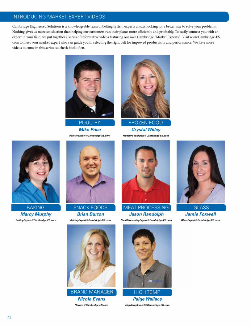
42
INTRODUCING MARKET EXPERT VIDEOS
Cambridge Engineered Solutions is a knowledgeable team of belting system experts always looking for a better way to solve your problems. Nothing gives us more satisfaction than helping our customers run their plants more efficiently and profitably. To easily connect you with an expert in your field, we put together a series of informative videos featuring our own Cambridge “Market Experts.” Visit www.Cambridge-ES.com to meet your market expert who can guide you in selecting the right belt for improved productivity and performance. We have more videos to come in this series, so check back often.
POULTRY FROZEN FOOD
BAKING SNACK FOODS MEAT PROCESSING GLASS
BRAND MANAGER HIGH TEMP
Mike [email protected]
Crystal [email protected]
Marcy [email protected]
Brian [email protected]
Jason [email protected]
Jamie [email protected]
Nicole [email protected]
Paige [email protected]
43
Global Headquarters105 Goodwill Road
Cambridge, MD 21613 USAwww.cambridge-es.com
Export Sales & ServiceThrough our Export Division, we export products to all parts of the world. We are experienced in preparing FAS, C&F and CIF quotations, processing of necessary documents, and handling of all types of export shipments. To serve our international customers, we also have a network of representatives around the world plus manufacturing and alses facilities in the United States, Brazil and Mexico.
At Cambridge Engineered Solutions, manufacturing outstanding quality products is only the beginning of our commitment to deliver total customer satisfaction. We provide all of the sales, service and engineering assistance you need via phone - 24/7/365.
How to order products
Toll-Free: 1.877.649.7492
Outside the U.S. & Canada: 1.410.901.2660
Fax: 1.410.901.8680
E-mail: [email protected]
Global Headquarters105 Goodwill Road
Cambridge, MD 21613 USA
toll-free: 1.877.649.7492
tel: 1.410.901.2660
fax: 1.410.901.8680
www.cambridge-es.com
CMB2-001 09/14