strata control in underground tunnels perspectives for...
TRANSCRIPT

61
Górnictwo i Geoin ynieria Rok 29 Zeszyt 3/2 2005
Tadeusz Majcherczyk , Piotr Ma kowski
STRATA CONTROL IN UNDERGROUND TUNNELS PERSPECTIVES FOR DEVELOPMENT
1. Introduction
Applying a proper type of support in an underground excavation mostly depends on mining and geological conditions as well as on the intended function of the excavation. In Polish coal mines the roof conditions force engineers to apply support systems with relati-vely big load capacities, often being a combination of several types of reinforcements.
Until the 1980s local brick lining reinforced by timber props or roof-bars was com-monly used. Nowadays, due to enormous depths of exploitation, practically only steel sup-port additionally reinforced with other steel elements is utilized in underground tunnels.
If we take stress distribution into consideration, arch support seems to be the optimal shape of lining as it takes over the load from the rock mass in the most convenient way, adapting itself to the parabolic or elliptic shape of the fracture zone, formed mostly in a tu-nnel’s roof [2].
As far as construction technology is concerned, a modern support should be:
— easy to install;
— suitable for different sizes of tunnels and changeable conditions of driving and main-taining tunnels;
— reliable at the joints of its component elements;
— easy to reinforce.
Analogically, if we take economics into consideration, a modern support type should be as inexpensive as possible, thus lighter constructions having proper strength should to be found.
The paper presents changes that have taken place in designing of tunnel support in Polish coal mines in the last decades.
AGH The University of Scence and Technology, Cracow, Poland
62
2. Selection of support type
At present, arched walls, lining, set support and roof bolting are commonly used in underground mining.
Arch walls made of brick, concrete pre-cast elements or concrete and reinforced concrete are recommended to be used in long-life tunnels and chambers located in rock mass with water inflow or strongly filled with gases, located however at small depths. For this reason, applying such a support at the depth of exploitation 800 1200 m is practically impossible.
Layer lining is recommended as an individual lining in long-life tunnels in competent rock mass (f 1.5) without water inflow. The choice of type of materials used for the lin-ing depends on geological conditions and they include: shotcrete, concrete reinforced with rockbolts or concrete reinforced with steel. Due to lack of flexibility of such lining, the demanded thickness of the layer should be greater than 1 m to protect an excavation in conditions of vertical stress in the rock mass exceeding 20 MPa. For this reason, shotcrete is applied usually at small depths (tunnels), where a layer with the thickness of between se-veral to 20 centimetres can guarantee the tunnels’ stability.
Although rockbolts, i.e. steel bars or steel ropes, are also stiff types of support, they possess numerous undisputable qualities, which are not characteristic of wall or layer lining.
The benefits of applying roof bolting are the following: — decreased cost of material, — smaller labour intensity, — increased labour safety, — limited dilution of output by the rock excavated during development works, — shortened time of longwall equipping, — better comfort of work at the crossings of top and bottom gates with the longwall, — limiting roof falls at the crossings of longwalls and the headings, — increasing longwalls’ advance through simplifying the crossings’ support system.
Taking difficult geological conditions in Polish coal mines and complicated tectonics into consideration, applying roof bolting is often complicated or even impossible. It turns out that the best support in terms of the character of its work is yielding arch support. It is flexible and can take rock mass load from any direction, adjusting to this in which the prevailing loads occur.
It may be assumed from the above considerations that roof bolting and set support are the types of support, whose application in deep underground mines is fully justified.
3. Advancing lining materials and technology of lining construction
Steel is a crucial material for constructing set supports and roof bolts. For the last few years, the quality of steel used for production of support units has increased considerably, which in turn increases the strength of individual elements of support as well as its whole construction.
63
3.1. Roof bolting
In the case of steel bolts, until recently St-3 or St-5 graded steel with tensile strength Rm = 300 500 MPa was applied. Actually, the load capacity of such bolts did not exceed approximately 160 200 kN.
Nowadays, for the sake of bolt production, steel with increased strength 18G2 or 18G2A graded steel with Rm minimum 550 MPa or 34GS graded steel with Rm = 600 MPa
is applied. In many cases, parameters of steel are even higher and, for example, for AP 770 graded steel (bolt APB) the tensile strength is Rm = 770 MPa and its guaranteed load capacity is 300 kN, and for EM 700 graded steel (bolt KG-345) the tensile strength is Rm = 700 MPa and the guaranteed load capacity is 275 kN [8, 10].
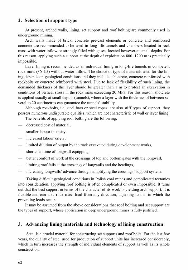
Plain smooth bars are practically not used any more. Their load capacity as proved by numerous tests is only 41.6% of the capacity of threaded bars and 27.6% of ribbed bars [20]. For better interaction with rock mass, spherical washers, not plain washers, are commonly applied nowadays. They afford better possibility of proper positioning of bolt nuts in relation to the surface irregularities of the roof or the steel element, with which the bolt works (Fig. 1) [10, 13].
Fig. 1. Example of a modern AP-type steel bolt with spherical seat [10]. 1 bar of the bolt, 2 M 24 nut with shear-pin, 3 profiled washer plate 8 150 150,
4 spherical seat, 5 antifriction ring
Also the end of the bolt has been changed in the recent years. For better mixing of grout or opening of grout cartridges, it is nowadays always single or double-ribbed, which gives approximately 20% higher load capacity in comparison to the plain cut end or but-terfly end [20].
In case of rope tendons, similarly to the production of steel bolts, better types of steel (e.g. EM700 graded steel) are used. In the construction of strands, plain cables are slowly withdrawn from production. Instead, cables with broadened sections (so-called cages) are applied. In this way, shearing strength of the area between the wire of the cable and the grout material is increased.

64
Fig. 2. Rope tendons with tensioning sleeves and Gifford clamps [11]: 1 rope, 2 plain washer, 3 Gifford damp, 4 tensioning sleeve and M30 nut
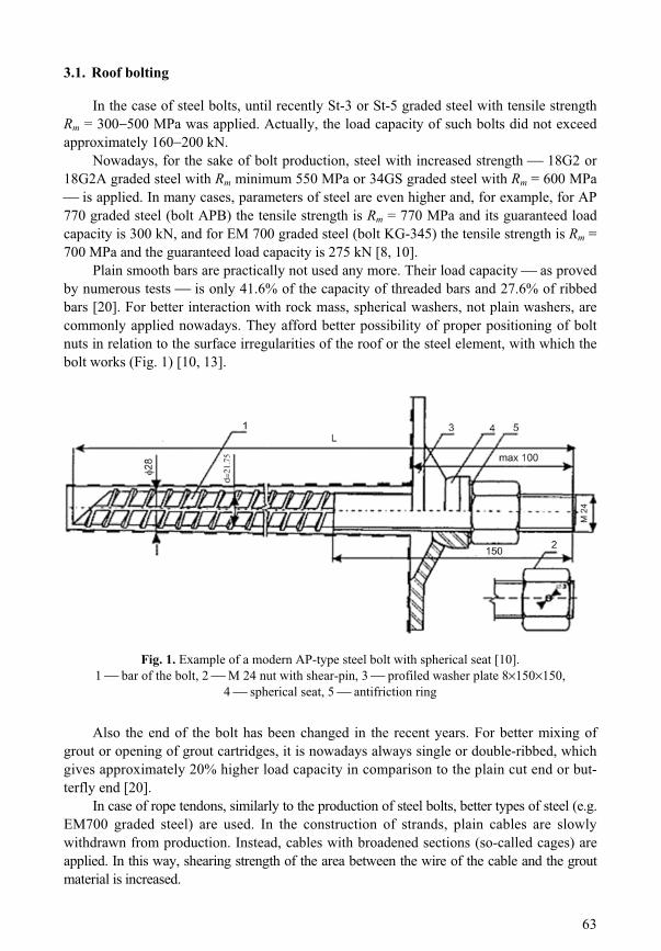
For the cage cables the load capacity is approximately 250 kN, for the cables with sleeves and Gifford clamps (Fig. 2) approximately 415 kN, for the so-called “mega-bolts” even 600 kN, with only 60 kN of load capacity for plain cables [8]. The follo-wing cables have the widest application: “nutcage” (with a ring on the core wire, around which the remaining wires are wound Fig. 3), “birdcage” (wires of the rope are rebound and tied with a clamp every set distance so the so-called “cages” are created) and “bulban-chor” (the wires of the cable create empty spaces along the length of up to 150 mm) [8, 11].
The technology of rope tendon installation has also been modified: more and more cables are not grouted with cement grout any more, but using resin cartridges. Using spe-cially prepared resin cartridges causes that the hole can have a smaller diameter (36 mm instead of 42 mm) and thus it can be drilled without flushing (damage of the hole’s walls causes cavities, and thus an increased use of grout), and, most of all, it does not require the use of specialist equipment for mixing and pumping the cement slurry [8].
65
Due to the fact that mining is frequently carried out in conditions of serious seismic hazard, for the last few years “burstproof” steel bolts have been produced (e.g. KG-type made of EM 700 graded steel, with load capacity of approxi-mately 350 kN, or IRW-type made of 40HM graded steel with the load capacity of approximately 430 kN.
We have to point out here that also grout cartridges are subject to evolutionary modifications. The strength of cart-ridges, denominated as compressive strength of resin, is higher and higher, similarly to their elastic modulus. “Geo-hifix” produced in Spain has the strength of Rc = 64 MPa and E = 13.2 GPa, German “Carbitech” Rc = 91 MPa and E = 17.3 GPa, and English “Exchem” Rc = 103 MPa and E = 22.1 GPa. These values are obtained thanks to the used fill materials usually calcium carbonate (CaCO3) or mag-nesium carbonate (MgCO3) making up to as much as 50 70% of the whole resin mass. The proportion of resin in the whole mass (usually polyester) of the cartridge is cur-rently approximately 25 50% [8].
3.2. Set support
In the case of set support, similarly to roof bolting, using steel with better parameters is the basic course of action to increase the strength of support elements. Although cons-truction steel of normal quality (mostly St-5 and 34GJ graded steel) is still in use, in the recent years the share of alloy steel (e.g. 31Mn4, or 15HG2Vcu graded alloy steel) has considerably increased in the production of support elements.
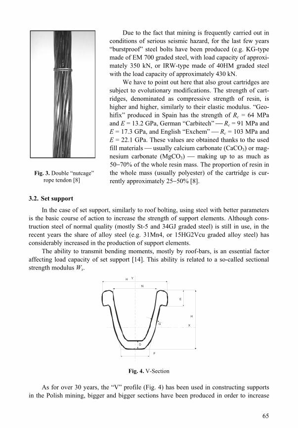
The ability to transmit bending moments, mostly by roof-bars, is an essential factor affecting load capacity of set support [14]. This ability is related to a so-called sectional strength modulus Wx.
G
D
Y
F
H
N
E
H
X
Fig. 4. V-Section
As for over 30 years, the “V” profile (Fig. 4) has been used in constructing supports in the Polish mining, bigger and bigger sections have been produced in order to increase
Fig. 3. Double “nutcage” rope tendon [8]

66
the bending resistance of supports. Unfortunately, a big section, apart from increased load capacity, has a considerable weight and increased price. At the turn of the 20th century, new sizes of sections were introduced V32 and V34 [12] with a very advantageous ratio of sectional modulus in relation to their weight and size. They differ from each other only by the wall thickness G (Fig. 4). Basic data regarding V sections currently produced are presented in Table 1 [12].
TABLE 1
Basic parameters of V32 and V34 sections in comparison to the sections produced earlier
Section Sectional strength modulus Wx [cm3]
HeightH [mm]
WidthK [mm]
Section area [cm2]
Weight[kg]
V25 83.0 118 135 31.8 25.0 V29 93.7 124 150 37.0 29.0 V32 121.2 137 171 40.8 32.1 V34 124.0 137 171 43.5 34.1 V36 136.5 138 171 45.7 35.9 V44 173.6 150 179 55.9 43.9
The number of clamps and their nominal fastening torque are essential factors increasing the load capacity of support. In difficult mining and geological conditions, not two, but three clamps are used and their load capacity when tightened with torque of 500600 Nm (profile V29 and higher) may reach the value of 400 470 kN [2].
Due to enormous depths of mining, parabolic shape of support gives better results in practice that is why approximately 99% of all underground tunnels are nowadays support-ed by steel arch sets.
Load bearing capacity of arch set support constitutes the capacity of a system, which consists of support units joined by spreaders, strapping, and also additional reinforcing su-pport elements such as lagging, which is an essential additional support element [4].
The loads of the rock mass will be properly transferred onto the support if lagging with high compressive strength and resistance to physical and chemical activity of water is used between the rock wall and the support. It may be assumed from the conducted mea-surements [3] that, in the case of lack of tight filling of the void between the support and the rock, load capacity of the support decreases by 28 36% (Tab. 2).
TABLE 2
Measured support bearing capacity [3]
Load-bearing capacity [kN/m] LaggingV21 V25 V29
Without lagging 319.4 390.4 460.6 With lagging 502.4 524.5 639.5
Strapping, for which specially made steel mesh is utilized, is nowadays designed to transmit considerable static load-tensile and bending stresses. The construction of mesh elements and the way of joining them allows for a quick, easy and safe installation, thus
67
making it possible to minimise the size of the necessary excavation. As the result, voids behind the support are minimized, which has a positive influence on stability and bearing capability of support [13].
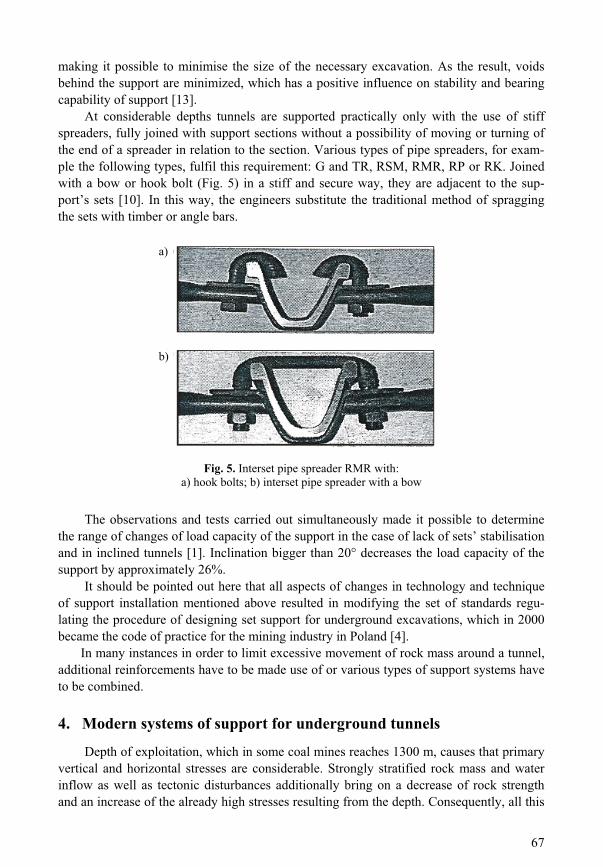
At considerable depths tunnels are supported practically only with the use of stiff spreaders, fully joined with support sections without a possibility of moving or turning of the end of a spreader in relation to the section. Various types of pipe spreaders, for exam-ple the following types, fulfil this requirement: G and TR, RSM, RMR, RP or RK. Joined with a bow or hook bolt (Fig. 5) in a stiff and secure way, they are adjacent to the sup-port’s sets [10]. In this way, the engineers substitute the traditional method of spragging the sets with timber or angle bars.
b)
a)
Fig. 5. Interset pipe spreader RMR with: a) hook bolts; b) interset pipe spreader with a bow
The observations and tests carried out simultaneously made it possible to determine the range of changes of load capacity of the support in the case of lack of sets’ stabilisation and in inclined tunnels [1]. Inclination bigger than 20 decreases the load capacity of the support by approximately 26%.
It should be pointed out here that all aspects of changes in technology and technique of support installation mentioned above resulted in modifying the set of standards regu-lating the procedure of designing set support for underground excavations, which in 2000 became the code of practice for the mining industry in Poland [4].
In many instances in order to limit excessive movement of rock mass around a tunnel, additional reinforcements have to be made use of or various types of support systems have to be combined.
4. Modern systems of support for underground tunnels
Depth of exploitation, which in some coal mines reaches 1300 m, causes that primary vertical and horizontal stresses are considerable. Strongly stratified rock mass and water inflow as well as tectonic disturbances additionally bring on a decrease of rock strength and an increase of the already high stresses resulting from the depth. Consequently, all this
a)
b)
68
leads to extreme loads on the support and causes floor heave. On the other hand, locally occurring favourable roof conditions give a possibility to limit the amount of support to be installed in an excavation. In the case of top and bottom gates, additional reinforcement of set support makes it possible to re-use them again.
Therefore, the modern systems of tunnel support have the following objectives [15]: — limiting the extent of the fracture zone, i.e. decreasing the load on the support; — taking optimal advantage of load capacity of a designed support system, especially in
the case of strong roof rocks; — reinforcing the floor of a tunnel, often in conjunction with the already existing support
system or by reinforcement of floor strata; — preserving integrity of gangways, especially behind the longwall front.
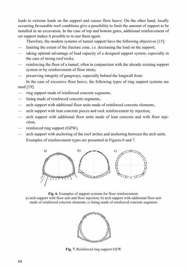
In the case of excessive floor heave, the following types of ring support systems are used [19]: — ring support made of reinforced concrete segments, — lining made of reinforced concrete segments, — arch support with additional floor units made of reinforced concrete elements, — arch support with lean concrete pieces and rock reinforcement by injection, — arch support with additional floor units made of lean concrete and with floor inje-
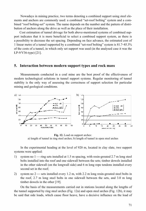
ction, — reinforced ring support (OZW), — arch support with anchoring of the roof arches and anchoring between the arch units.
Examples of reinforcement types are presented in Figures 6 and 7.
c)b)a)
Fig. 6. Examples of support systems for floor reinforcement: a) arch support with floor unit and floor injection; b) arch support with additional floor unit
made of reinforced concrete elements; c) lining made of reinforced concrete segments
Fig. 7. Reinforced ring support OZW
a) b) c)

69
In strongly stratified rocks with considerable water inflow and in the areas with highly developed tectonics, special support types are used (Fig. 8) [7]. These constructions are also used in large-size excavations, e.g. cross-overs, equalising chambers, pump chambers etc. Special supports are made of heavy sections (V36-type and V44-type), which have special shapes (elliptic and round); on the perimeter of the excavation there are local rein-forcements (shotcrete, injections); the arches are installed to create double or triple bearing rings or the lining is constructed of prefabricated or concrete elements [6].
However, other than standard support systems, especially mixed with concrete, are expensive, therefore their application is relatively rare.
b)a)
Fig. 8. Examples of special support systems for complex mining and geological conditions: a) arch support with shotcrete and anchors;
b) arch-steel-concrete support with internal and external sets
Fig. 9. PX support set construction system
Crosswise stabilisation of sets, which was discussed in chapter 3, can be done by us-ing special constructions of sets, so-called PX support [21]. It is a three-dimensional system of arches set on the floor (Fig. 9). The system consists of two pairs of sets of the
P-type, inclined to each other at the angle of 20 25 and joined by two-yoke clamps and in the roof part by special linking elements. According to the conducted mea-
surements, load capacity of such a support for the sets size 10 made in 25G2 graded steel is as much as 860 kN, whereas for the P-10-type of support without any reinforcement it is 759 kN [21].
a) b)

70
Fig. 10. Anchoring the arches of yielding steel support
The most popular way to reinforce support of a tunnel in difficult conditions is to use a combination of sets and roof bolting [16]. This may be done by reinforcing the arches of the support, mainly roof pieces (Fig. 10) or also by anchoring between the arches (Fig. 11). Applying such a kind of support, which combines stiff support with yielding sets, is bene-ficial for the reinforcement of rock around the tunnel, because it takes advantage of self-supporting capacity of the rock mass and provides for supporting of the scaling rock in the future. Creating an anchored layer of rocks above the tunnel makes it possible to increase the spacing between the steel sets and fully take advantage of their load capacity.
650
350
150
2 .5m
Steel barsMesh
Steel resin bolts
Fig. 11. Anchoring between arches of yielding steel support
71
Nowadays in mining practice, two terms denoting a combined support using steel ele-ments and anchors are commonly used: a combined “set-roof bolting” system and a com-bined “roof bolting-set” system. The name depends on the number and the pattern of distri-bution of anchors along the drive as well as the place of their installation.
Cost estimation of tunnel drivage for both above-mentioned systems of combined sup-port indicates that it is more beneficial to select a combined support system, as there is a possibility to decrease the set spacing. Depending on face advance, the estimated cost of 1 linear metre of a tunnel supported by a combined “set-roof bolting” system is 81.7 85.3% of the costs of a tunnel, in which only set support was used (in the analysed case it was the
P-9/V36-type) [21].
5. Interaction between modern support types and rock mass
Measurements conducted in a coal mine are the best proof of the effectiveness of modern technological solutions in tunnel support systems. Regular monitoring of tunnel stability is the only way of assessing the correctness of support selection for particular mining and geological conditions.
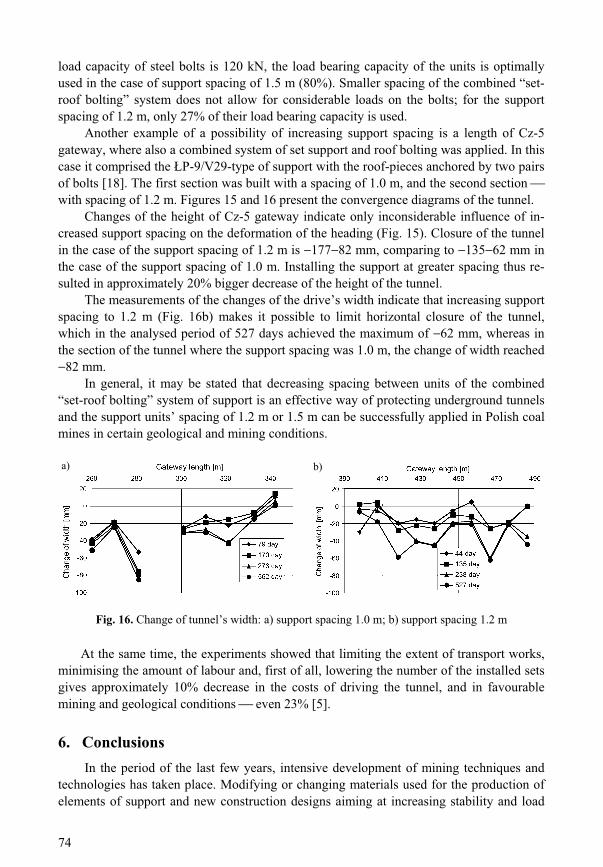
Fig. 12. Load on support arches: a) length of tunnel in ring steel arches; b) length of tunnel in open steel arches
In the experimental heading at the level of 920 m, located in clay slate, two support systems were applied: 1) system no 1 ring sets installed at 1.5 m spacing, with resin-grouted 2.7 m long steel
bolts installed into the roof and one sidewall between the sets; timber dowels installed in the other sidewall (on the longwall side) and 6 m long rope tendons installed every second set in the roof;
2) system no 2 sets installed every 1.2 m, with 2.2 m long resin-grouted steel bolts in the roof, 2.7 m long steel bolts in one sidewall between the sets, and 3.0 m long timber dowels in the other [19]. On the basis of the measurements carried out in stations located along the lengths of
the tunnel supported by ring steel arches (Fig. 12a) and open steel arches (Fig. 12b), it may be said that side loads, which cause floor heave, have a decisive influence on the load of

72
the sets. In the case of the ring support, the side-pieces carry almost two-times higher loads than the roof piece. Thus it is the floor pressure, which constitutes active deforming load of sets because of the closed construction of the sets. In the case of open steel arches, the load on the roof-piece is two times higher, and the sidewall only to a minimum degree resists the load from rock mass. At the same time, the construction causes (system no 2) that the load from the floor is transferred onto the support arches two times faster. Roof bolting enables in this case proper interaction between arch support and rock mass, simultaneously reinforcing rock strata around the tunnel.
In order to compare the influence of anchors on the performance of set support in Cz-5a gateway, the tunnel was divided into two sections: one section was reinforced by traditional P-9/V29-type of support and in the second section the support arches were anchored with one pair of bolts. The spacing of the support was 1 m and there was sandy shale in the roof of the tunnel [17].
a) b)
Fig. 13. Change of heading’s height: a) without anchoring; b) with anchoring of roof-bar arches
Convergence measurements (Fig. 13) indicated that anchoring roof-pieces of the arches considerably limits the movements of rock strata around the heading, especially in the initial period of its existence. Roof convergence in the stretch of the drive, in which bolts were applied, was less than 38 mm, whereas in the part without bolts, the roof’s con-vergence was almost 350 mm. Thus, anchoring the roof-piece of the arch resulted in roof movement of only 60 80 mm on average, whereas in the part without bolts, the move-ment was more than 100 mm (even 227 mm Fig. 13a).
Figures 14a and 14b present the graphs of changes of axial forces in the rockbolts installed in Izn incline, where a combined “set-roof bolting” system of support with the spacing between sets of 1.2 m and 1.5 m was applied, with the reinforcement of sets by two pairs of 2.5 m long bolts. The spacing between the units of the combined support sys-tem were increased, as its standard set spacing is 1.0 m [15, 16].
Along the test length of the tunnel, where the spacing of support was increased from 1.2 m to 1.5 m, almost double values of forces in the installed rockbolts were measured. The maximum value of axial force of 95 kN occurred at the height of 1.2 m. Although value of the force transmitted by a bolt constantly grew, it may be however noticed that in the initial length of the bolt a compressive force of 20 kN was obtained, and after 47 days of measurements, the bolt already transmitted a force of approximately 42 kN (Fig. 15a).

73
a) b)
Fig. 14. Axial force diagram in selected periods of time for instrumented bolts in the combined “set support-roof bolting” system of lining: a) spacing of sets 1.2 m; b) spacing of sets 1.5 m
The bolt installed in the part of the drive where support spacing was 1.2 m, until the 82nd day of measurements did not transmit forces higher than 16 kN (final section of the bolt 2.1 m Fig. 15b). Further measurements indicated the increase of forces, which after 458 days of measurements reached the maximum value of 33 kN. It is worth noticing that the forces in the respective sections of the bolt not only were increasing, but also de-creasing, which proves that in the anchored roof, apart from tensile, there are also com-pressive stresses.
b)a)
Fig. 15. Change of tunnel’s height: a) support spacing: 1.0 m; b) support spacing 1.2 m
The above example of the application of a combined system of set and roof bolting support shows that a 1.5-metre spacing of support gives the load of bolts of approximately 96 kN, and the spacing of 1.2 m only 33 kN. Considering the fact that the guaranteed
74
load capacity of steel bolts is 120 kN, the load bearing capacity of the units is optimally used in the case of support spacing of 1.5 m (80%). Smaller spacing of the combined “set- roof bolting” system does not allow for considerable loads on the bolts; for the support spacing of 1.2 m, only 27% of their load bearing capacity is used.
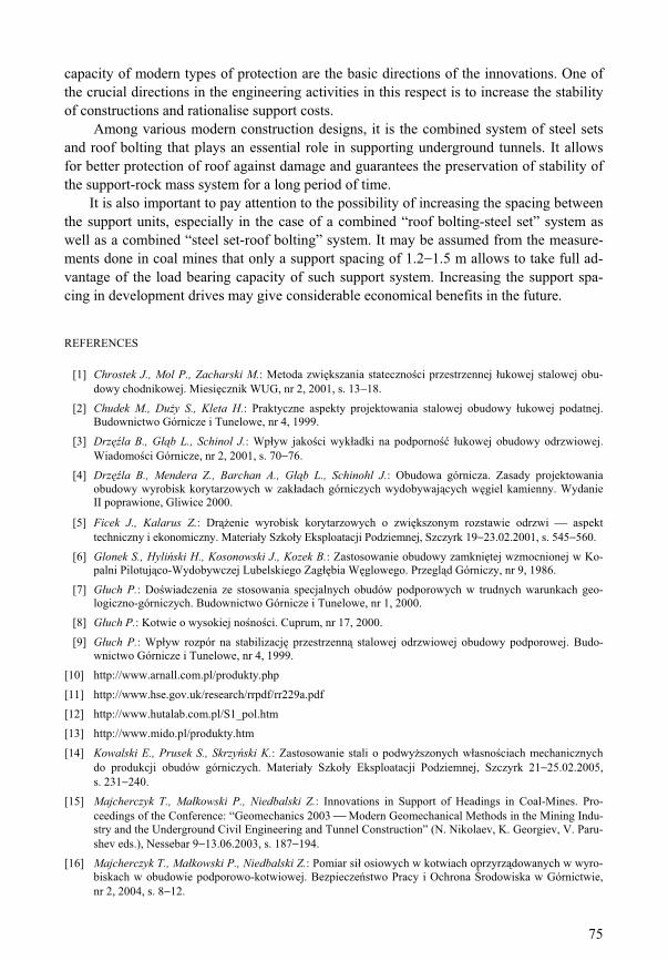
Another example of a possibility of increasing support spacing is a length of Cz-5 gateway, where also a combined system of set support and roof bolting was applied. In this case it comprised the P-9/V29-type of support with the roof-pieces anchored by two pairs of bolts [18]. The first section was built with a spacing of 1.0 m, and the second section with spacing of 1.2 m. Figures 15 and 16 present the convergence diagrams of the tunnel.
Changes of the height of Cz-5 gateway indicate only inconsiderable influence of in-creased support spacing on the deformation of the heading (Fig. 15). Closure of the tunnel in the case of the support spacing of 1.2 m is 177 82 mm, comparing to 135 62 mm in the case of the support spacing of 1.0 m. Installing the support at greater spacing thus re-sulted in approximately 20% bigger decrease of the height of the tunnel.
The measurements of the changes of the drive’s width indicate that increasing support spacing to 1.2 m (Fig. 16b) makes it possible to limit horizontal closure of the tunnel, which in the analysed period of 527 days achieved the maximum of 62 mm, whereas in the section of the tunnel where the support spacing was 1.0 m, the change of width reached
82 mm. In general, it may be stated that decreasing spacing between units of the combined
“set-roof bolting” system of support is an effective way of protecting underground tunnels and the support units’ spacing of 1.2 m or 1.5 m can be successfully applied in Polish coal mines in certain geological and mining conditions.
b) a)
Fig. 16. Change of tunnel’s width: a) support spacing 1.0 m; b) support spacing 1.2 m
At the same time, the experiments showed that limiting the extent of transport works, minimising the amount of labour and, first of all, lowering the number of the installed sets gives approximately 10% decrease in the costs of driving the tunnel, and in favourable mining and geological conditions even 23% [5].
6. Conclusions In the period of the last few years, intensive development of mining techniques and
technologies has taken place. Modifying or changing materials used for the production of elements of support and new construction designs aiming at increasing stability and load
75
capacity of modern types of protection are the basic directions of the innovations. One of the crucial directions in the engineering activities in this respect is to increase the stability of constructions and rationalise support costs.
Among various modern construction designs, it is the combined system of steel sets and roof bolting that plays an essential role in supporting underground tunnels. It allows for better protection of roof against damage and guarantees the preservation of stability of the support-rock mass system for a long period of time.
It is also important to pay attention to the possibility of increasing the spacing between the support units, especially in the case of a combined “roof bolting-steel set” system as well as a combined “steel set-roof bolting” system. It may be assumed from the measure-ments done in coal mines that only a support spacing of 1.2 1.5 m allows to take full ad-vantage of the load bearing capacity of such support system. Increasing the support spa-cing in development drives may give considerable economical benefits in the future.
REFERENCES
[1] Chrostek J., Mol P., Zacharski M.: Metoda zwi kszania stateczno ci przestrzennej ukowej stalowej obu-dowy chodnikowej. Miesi cznik WUG, nr 2, 2001, s. 13 18.
[2] Chudek M., Du y S., Kleta H.: Praktyczne aspekty projektowania stalowej obudowy ukowej podatnej. Budownictwo Górnicze i Tunelowe, nr 4, 1999.
[3] Drz la B., G b L., Schinol J.: Wp yw jako ci wyk adki na podporno ukowej obudowy odrzwiowej. Wiadomo ci Górnicze, nr 2, 2001, s. 70 76.
[4] Drz la B., Mendera Z., Barchan A., G b L., Schinohl J.: Obudowa górnicza. Zasady projektowania obudowy wyrobisk korytarzowych w zak adach górniczych wydobywaj cych w giel kamienny. Wydanie II poprawione, Gliwice 2000.
[5] Ficek J., Kalarus Z.: Dr enie wyrobisk korytarzowych o zwi kszonym rozstawie odrzwi aspekt techniczny i ekonomiczny. Materia y Szko y Eksploatacji Podziemnej, Szczyrk 19 23.02.2001, s. 545 560.
[6] Glonek S., Hyli ski H., Kosonowski J., Kozek B.: Zastosowanie obudowy zamkni tej wzmocnionej w Ko-palni Pilotuj co-Wydobywczej Lubelskiego Zag bia W glowego. Przegl d Górniczy, nr 9, 1986.
[7] G uch P.: Do wiadczenia ze stosowania specjalnych obudów podporowych w trudnych warunkach geo-logiczno-górniczych. Budownictwo Górnicze i Tunelowe, nr 1, 2000.
[8] G uch P.: Kotwie o wysokiej no no ci. Cuprum, nr 17, 2000.
[9] G uch P.: Wp yw rozpór na stabilizacj przestrzenn stalowej odrzwiowej obudowy podporowej. Budo-wnictwo Górnicze i Tunelowe, nr 4, 1999.
[10] http://www.arnall.com.pl/produkty.php
[11] http://www.hse.gov.uk/research/rrpdf/rr229a.pdf
[12] http://www.hutalab.com.pl/S1_pol.htm
[13] http://www.mido.pl/produkty.htm
[14] Kowalski E., Prusek S., Skrzy ski K.: Zastosowanie stali o podwy szonych w asno ciach mechanicznych do produkcji obudów górniczych. Materia y Szko y Eksploatacji Podziemnej, Szczyrk 21 25.02.2005, s. 231 240.
[15] Majcherczyk T., Ma kowski P., Niedbalski Z.: Innovations in Support of Headings in Coal-Mines. Pro-ceedings of the Conference: “Geomechanics 2003 Modern Geomechanical Methods in the Mining Indu-stry and the Underground Civil Engineering and Tunnel Construction” (N. Nikolaev, K. Georgiev, V. Paru-shev eds.), Nessebar 9 13.06.2003, s. 187 194.
[16] Majcherczyk T., Ma kowski P., Niedbalski Z.: Pomiar si osiowych w kotwiach oprzyrz dowanych w wyro-biskach w obudowie podporowo-kotwiowej. Bezpiecze stwo Pracy i Ochrona rodowiska w Górnictwie, nr 2, 2004, s. 8 12.
76
[17] Majcherczyk T., Niedbalski Z.: Ocena obudowy podporowo-kotwiowej na podstawie wybranych bada in situ. Przegl d Górniczy, nr 12, 2002, s. 1 7.
[18] Majcherczyk T., Niedbalski Z.: Rozrzedzanie obudowy podporowej w wietle wyników bada kopalnia-nych. Przegl d Górniczy, nr 5, Katowice 2004.
[19] Piechota S., Korzeniowski W., Stachowicz S.: Obudowa mieszana chodników przy cianowych w Kopalni W gla Kamiennego “Bogdanka”. Wiadomo ci Górnicze, nr 4, 2000, s. 168 177.
[20] Piechota S., Stopyra M., Stasica J.: Wp yw konstrukcji erdzi kotwi wklejanej na efektywno jej utwier-dzenia. Przegl d Górniczy, nr 7 8, 2002, s. 35 41.
[21] Ru ka K., Kowalski E., Rotkegel M.: Obudowa PX skuteczny rodek utrzymania stateczno ci wyrobisk korytarzowych. Materia y Szko y Eksploatacji Podziemnej, Szczyrk 21 25.02.2000, s. 329 338.