strategy and results of high heat flux testing of european ... documents/diverto… · h. greuner,...
TRANSCRIPT

H. Greuner, IPP Garching 1 2nd Technical Meeting on Divertor Concepts (IAEA) Nov. 13-16, 2017, Suzhou, China
Strategy and results of high heat flux testing of European DEMO divertor mock-ups
H. Greunera, B. Böswirtha, T. Barrettb, M. Richoud, E. Viscac and J-H. Youa
aMax Planck Institute for Plasma Physics, Boltzmann Str. 2, 85748 Garching, Germany
bCCFE, Culham Science Centre, Abingdon OX14 3DB, United Kingdom cENEA, Unità Tecnica Fusione, ENEA C. R. Frascati, via E. Fermi 45, 0 0 044 Frascati, Italy
dCEA, IRFM, F-13108 Saint Paul Lez Durance, France
Motivation: The successful development of divertor plasma-facing components (PFCs) for DEMO requires high heat flux testing (HHF) to assess the performance and the expected lifetime. • Only HHF loading can generate thermo-mechanical stress similar to the expected operating
conditions in a fusion device • Other test procedures do not consider this complex thermo-mechanical behaviour during
cyclic HHF loading
Max-Planck-Institut für Plasmaphysik

H. Greuner, IPP Garching 2 2nd Technical Meeting on Divertor Concepts (IAEA) Nov. 13-16, 2017, Suzhou, China
Outline
1) Strategy of HHF testing • Introduction • Heat transfer, CHF of cold and hot-water cooling • Testing procedure
2) HHF testing • GLADIS facility • examples of test results
3) Summary, outlook and conclusion

H. Greuner, IPP Garching 3 2nd Technical Meeting on Divertor Concepts (IAEA) Nov. 13-16, 2017, Suzhou, China
Status of highly heat flux loaded ITER divertor PFCs Design criteria of W monoblock components: • 10 MW/m² steady-state, 5000 cycles experimentally confirmed,
respectively 30,0001) based on fatigue FEM, 70 °C water inlet, • 300 cycles at 20 MW/m², slow transients up to 10 s • max. 0.1 dpa neutron dose in W The reliability of the world wide developed technologies of W -PFCs has been confirmed by intensive HHF tests up to 5000 cycles
1. Strategy of HHF testing - Introduction
Challenges for DEMO Expected neutron dose during 2 full power operation years: • 4 dpa in W, 13 dpa in CuCrZr cooling tubes, however lower cycle number Embrittlement of materials requires the development of new target concepts according to the specific operation in DEMO Design criteria: • 10 MW/m², nominal steady-state operation,150 °C water inlet, 50 bar, 16 m/s • 20 MW/m², during slow transients up to 10 s
1) M. Merola, ICFRM-18 2017
Typical ITER W monoblock mock-ups (blocks ~ 25 x 28 x 12 mm³)

H. Greuner, IPP Garching 4 2nd Technical Meeting on Divertor Concepts (IAEA) Nov. 13-16, 2017, Suzhou, China
HHF test strategy of “phase I”
• Experimental validation of the FEM predicted thermo-mechanical behaviour under DEMO relevant heat loads and cooling conditions
• HHF tests of three mock-ups of each concept • Standard test procedure for HHF test facilities (currently only GLADIS involved)
Test procedure: 1. Step: cold-water, low pressure (20°C inlet, 10 bar static, 12 m/s) as “initial assessment” to reduce risks & operational costs of the test facility: 1. screening of each mock- up up to 20 – 25 MW/m², 2. 100 cycles 10 s at 10, 15, 20 MW/m²
Aim: Selection of the most promising target concept(s) for the phase II of target development
2. Step: hot-water, high pressure (130°C inlet, 40 bar, 16 m/s) screening and fatigue tests 3. screening up to 20 MW/m², 4. extended cycling up to 300 (1000) cycl. at 20 MW/m², 10 s for one mock-up of each concept
H. Greuner, IPP Garching 5 2nd Technical Meeting on Divertor Concepts (IAEA) Nov. 13-16, 2017, Suzhou, China
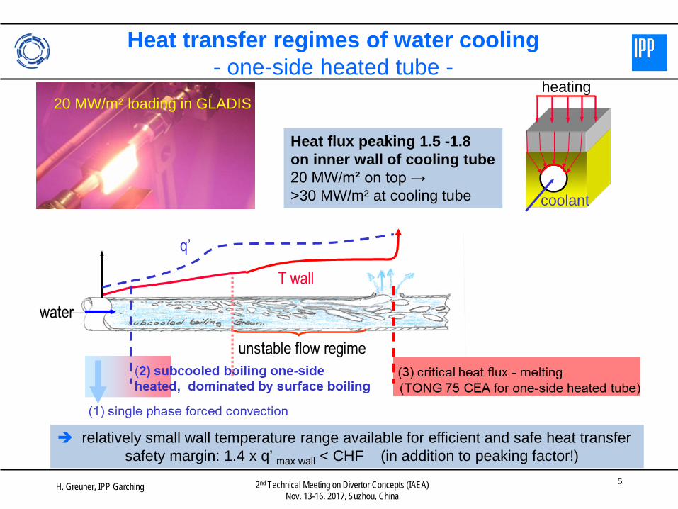
Heat transfer regimes of water cooling - one-side heated tube -
heating
coolant
Heat flux peaking 1.5 -1.8 on inner wall of cooling tube 20 MW/m² on top → >30 MW/m² at cooling tube
relatively small wall temperature range available for efficient and safe heat transfer safety margin: 1.4 x q’ max wall < CHF (in addition to peaking factor!)
20 MW/m² loading in GLADIS

H. Greuner, IPP Garching 6 2nd Technical Meeting on Divertor Concepts (IAEA) Nov. 13-16, 2017, Suzhou, China
Comparison of heat transfer and CHF - HHF tests versus DEMO requirements -
“cold-water testing”, safe heat transfer, high CHF, corresponds to ~ 30 MW/m² “component load”
Heat load tests > 20 MW/m² on the component should be performed at 20 °C inlet only
• Relatively small temp. diff. to “hot-water” at higher heat loads, about 50 °C only 130°C water-cooling in GLADIS similar to DEMO heat transfer conditions • To avoid onset of CHF, local heat flux at the inner wall should be < 35 MW/m² the heat load on the component should be limited to ~22 MW/m²
H. Greuner, IPP Garching 7 2nd Technical Meeting on Divertor Concepts (IAEA) Nov. 13-16, 2017, Suzhou, China
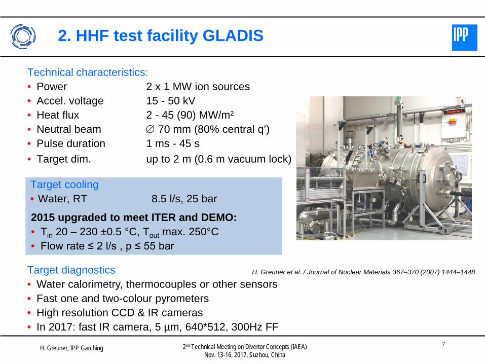
2. HHF test facility GLADIS
Technical characteristics: • Power 2 x 1 MW ion sources • Accel. voltage 15 - 50 kV • Heat flux 2 - 45 (90) MW/m² • Neutral beam ∅ 70 mm (80% central q’) • Pulse duration 1 ms - 45 s • Target dim. up to 2 m (0.6 m vacuum lock)
H. Greuner et al. / Journal of Nuclear Materials 367–370 (2007) 1444–1448
Target cooling • Water, RT 8.5 l/s, 25 bar
2015 upgraded to meet ITER and DEMO: • Tin 20 – 230 ±0.5 °C, Tout max. 250°C • Flow rate ≤ 2 l/s , p ≤ 55 bar
Target diagnostics • Water calorimetry, thermocouples or other sensors • Fast one and two-colour pyrometers • High resolution CCD & IR cameras • In 2017: fast IR camera, 5 µm, 640*512, 300Hz FF

H. Greuner, IPP Garching 8 2nd Technical Meeting on Divertor Concepts (IAEA) Nov. 13-16, 2017, Suzhou, China
Screening tests, hot-water 130°C, 40 bar, 16 m/s
Comparison of measured and calculated surface temperatures for two different target concepts • Thermal break concept (27 mm) → mitigate local heat flux concentration at cooling tube • Wf reinforced Cu tube (22 mm) → enhance high-temp. strength of Cu
10 MW/m² steady state for both concepts o.k., q’ > 15 MW/m² results in recrystallization
H. Greuner, IPP Garching 9 2nd Technical Meeting on Divertor Concepts (IAEA) Nov. 13-16, 2017, Suzhou, China
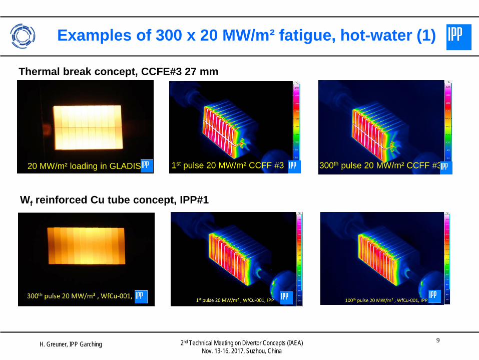
Examples of 300 x 20 MW/m² fatigue, hot-water (1)
Thermal break concept, CCFE#3 27 mm
1st pulse 20 MW/m² CCFF #3 300th pulse 20 MW/m² CCFF #3 20 MW/m² loading in GLADIS
Wf reinforced Cu tube concept, IPP#1

H. Greuner, IPP Garching 10 2nd Technical Meeting on Divertor Concepts (IAEA) Nov. 13-16, 2017, Suzhou, China
W surface images after 20 MW/m² cycling
Thermal break concept, CCFE#3 27 mm Tsurf during loading ~ 2000°𝐶
Thermal break concept, CCFE#6 22 mm Tsurf during loading ~ 1700°𝐶
• Both concepts, no cracks, loss of grains or strongly increased surface roughness • 27 mm mock-ups: recrystallization and grain growth of W surfaces clearly visible • 22 mm mock-ups: much less pronounced
300 pulses 20 MW/m² CCFE # 3 27 mm block width
4 mm
300 pulses 20 MW/m² CCFE # 6 22 mm block width
4 mm

H. Greuner, IPP Garching 11 2nd Technical Meeting on Divertor Concepts (IAEA) Nov. 13-16, 2017, Suzhou, China
Thin graded interlayer CEA FGM #4
DEMO type ENEA#5 300th pulse 20 MW/m² loading, 130°C
© E2M, IPP 2017
Examples of 300 x 20 MW/m² fatigue, hot-water (2)

H. Greuner, IPP Garching 12 2nd Technical Meeting on Divertor Concepts (IAEA) Nov. 13-16, 2017, Suzhou, China
Target concepts
Water temp. (°C)
Screening tests (MW/m²)
Fatigue tests 100 x (MW/m²)
Results
Extended cycling 300 x 20 MW/m² (status: 10/11/2017)
DEMO type (ENEA), 3 mock-ups
20 6 – 20 10 successful -
130 6 – 20 20 successful successful
ITER-like (ENEA), 3 mock-ups
20 6 – 20 10, 15 successful -
130 6 – 20 20 successful successful
Thermal break layer (CCFE), 3 x 2 mock-ups
20 6 – 25 10, 15, 20 successful -
130 6 – 20 10, 15, 20 successful successful
W-Cu composite block (IPP), 1 mock-up
20 6 – 22 20 successful (crack at cycle 362)
-
Wf Cu composite tube (IPP), 1 mock-up
20 6 – 20 10 successful -
130 6 – 20 20 successful successful
Thin graded interlayer (CEA), 3 x 2 mock-ups
20 6 – 25 10, 15, 20 successful -
130 6 – 20 10, 15, 20 successful successful
Summary table phase I HHF tests

H. Greuner, IPP Garching 13 2nd Technical Meeting on Divertor Concepts (IAEA) Nov. 13-16, 2017, Suzhou, China
Summary and conclusion
Summary • Cold water tests of all EU concepts as initial successfully performed • 300 cycles at 20 MW/m² 130°C hot-water of all EU W monoblock concepts successfully
performed • no serious surface or component damage occurred, all 20 tested mock-ups survived • good agreement between FEM predicted and measured surface temperatures • Indication of recrystallization and grain growth of W surface after 20 MW/m² cycling
Outlook • NDE after performed HHF loading • Micrographs of selected mock-ups
• Investigation of recrystallization depth, grain size • Investigation of W/ Cu interface, plastic deformation, delamination, cracks
Conclusion • A number of European manufacturers are able to produce advanced W divertor PFCs for
DEMO application. These water-cooled components are able to withstand up to 20 MW/m² cyclic heat load
• Important R&D progress in the last years