strategy for modifying and operating … the weight doubles the stretch or deflection. this behavior...
TRANSCRIPT

Operating Dies at a Common Shut Height Rev July 3, 2005 © 1989-2005 Smith & Associates 530 Hollywood Drive Monroe, Michigan 48162-2943
OPERATING DIES AT A COMMON SHUT HEIGHT
An important way to achieve first hit capability while reducing setup time is to maintain dies at a common shut height. This avoids the need to make shut height adjustments when changing most dies. However, there are precautions and sources of error that need attention. Definition of Shut Height Die shut height is defined as the height of the die in the shut or closed position. This height may be greater when measured on the shop floor than in the press because the die might not close completely because of die pressure systems. The press shut height for diesetting purposes is the distance from the top of the bolster to the bottom of the ram or slide at bottom dead center, (BDC). BDC is the 180° or six o’clock position of the press. It is not necessary to use a common shut height throughout the pressroom. An example of how dies may be grouped follows:
1. The line dies used to make a family of similar parts on one or more press lines form a group for standard shut height analysis.
2. In the same way, for double action presses, the draw die punch and blankholder
shut heights are the same on symmetrically opposite right and left-hand dies. 3. This procedure is a basic procedure for groups of dies that are similar.
If it is not practical to use a common shut height for all dies, he jobs changed most often are the logical dies to modify to start your common shut height project. Often, several groups of shut heights are required. For example, a series of small progressive dies may operate at a shut height 14-inches (355.6 mm). Automotive fender dies might require 72- inches (1829 mm). A well thought-out common height strategy can both speed up diesetting and help avoid die and press damage.1.2
1 D. Smith, Adjusting Dies to a Common Shut Height, SME/FMA Technical Paper TE89-565, Society of Manufacturing Engineers, Dearborn, Michigan, 1989. 2 D. Smith, How to Improve Hit-to-hit Time With a Tonnage Monitor, SME Technical Paper TE88-780, © Society of Manufacturing Engineers, Dearborn, Michigan, 1989.
1

Operating Dies at a Common Shut Height Rev July 3, 2005 © 1989-2005 Smith & Associates 530 Hollywood Drive Monroe, Michigan 48162-2943
Common Pass Height adds Advantages Operations varying from large automotive and tandem line dies, transfer press dies to small progressive dies should be set up to run at a common feed or pass height. Generally, this should be as high as possible for the following reasons:
1. Presses operated near their maximum shut height adjustment wherever possible maximize adjustment screw engagement, which avoids uneven screw wear.
2. A common pass height will avoid the need to make vertical adjustments to the
feeders or loaders in both coil and cut blank fed presses. 3. Making the pass height as high as possible provides for steep scrap chutes to
improve dependable scrap discharge. Avoiding Damage during Conventional Die Setup Serious delays, press damage and die damage result from insufficient shut height during setup. Checking the shut height before closing the press is required for manual diesetting. Another way to avoid damage is to inch the press slowly while watching the crankshaft degree indicator and slide position relative to the die setup or bottoming blocks. When inching large presses during changeover, it is important to notify your fellow workers in the area that you are going to inch the press. A final precaution is to hit the inch buttons briefly a couple of times to actuate the brake. This makes a distinct sound alerting persons in the area that a slide move is about to occur. Presses equipped with Eaton Dynamatic™ Constant Energy System clutches usually have a low inch selector, which limits torque.
Limitations of Automatic Shut Height Adjusters
Automatic shut height adjusters, like any electromechanical device have systematic inaccuracies. These errors must be determined and included in expected system performance. Remember, to assume is to blunder!
Sources of Shut Height Readout Error Having a shut height indicator is not a cure all for avoiding such damage. Some types of shut height indicators can lose their memory should power to the press be shut off. In addition, internal back-up batteries can fail. This can result in an incorrect figure being displayed. Caution during inching must always be the rule. In addition, there is no guarantee that any one shut height indicator will agree with another of the same type. Some indicators use a rotary resolver to measure the number of revolutions of the slide adjustment mechanism. This is then converted into inch or metric units.
2

Operating Dies at a Common Shut Height Rev July 3, 2005 © 1989-2005 Smith & Associates 530 Hollywood Drive Monroe, Michigan 48162-2943
Uneven screw wear and inaccurate calibration were other sources of error when the unit was installed. Take extra care when setting a die in a press that is different from the one in which the die shut height was calibrated.
Figure 1. Mechanical shut height readout on a press slide. These units are excellent for observing the relative effect of small adjustments.
Mechanical Readout Devices Mechanical shut height readout on a press slide is illustrated in Figure 1. These units are excellent for observing relatively small adjustments. However, be aware that if a mechanical failure should occur catastrophic press and die damage can result.
Data Entry Error Some presses are equipped with a means to automatically adjust the shut height to a preset value based on a computerized library of correct settings for each job. In such cases, obtaining the correct setting usually depends upon the diesetter entering the correct die or job number.
Again, to assume is to risk a dangerous blunder. A miscommunication or a keypad entry error can quickly result in thousands of dollars lost due to wrecked tooling and press damage. A Dangerous Assumption Many writers and speakers on the subject of setup reduction cite die shut heights standardization as a simple process of making all die shut heights the same as the press shut heights. This is correct as far as the concept is concerned.
However, in cases where tonnage requirements at the bottom of the stroke differ greatly from job to job, serious difficulties can result from such a simple assumption. This is because corrections for die and press deflection are required if the correct tonnage is to be achieved.
3

Operating Dies at a Common Shut Height Rev July 3, 2005 © 1989-2005 Smith & Associates 530 Hollywood Drive Monroe, Michigan 48162-2943
Figure 2. The relationship of spring load to spring deflection demonstrates Hooke's Law. (A) 5-inch (127 mm) undeflected length. (B) a 10-pound (4.55 kg) weight stretches the spring 1-inch (25.4 mm) to a length of 6-inches (152.4 mm). (C) a 20-pound (9.09 kg) weight stretches the spring 2-inches (50.8 mm) beyond its undeflected length to 7-inches (177.8 mm). Smith & Associates It is possible to make a slide adjustment on a press when changing dies even with widely differing tonnage requirements are involved. To achieve this desirable goal, an understanding of how mechanical presses actually develop tonnage is helpful. How A Press Develops Tonnage When the shut height is adjusted so the die halves just touch, zero tonnage is developed. To develop tonnage, the shut height must be reduced further. When this is done, the die is actually compressed slightly and, at the same time, parts of the press such as columns, links, pitmans, ram, bed, tie rods, and other parts are either compressed or stretched. This occurs because the press and die must obey the same physical laws that describe the behavior of a coiled steel spring. A Lesson from a Coiled Spring A coiled spring produces no force in its relaxed position. It must be either compressed or stretched to produce a force. Just as a coil spring deflects an amount that is proportional to applied pressure within its working limits, a press and die deflect an amount that is directly in proportion to developed tonnage within the maximum ratings of the press.
4

Operating Dies at a Common Shut Height Rev July 3, 2005 © 1989-2005 Smith & Associates 530 Hollywood Drive Monroe, Michigan 48162-2943
Figure 2 illustrates three coiled springs supported by a beam. The spring stretches in a uniform way as shown. Doubling the weight doubles the stretch or deflection. This behavior of springs has excellent repeatability if the spring is not overloaded and permanently stretched. Hooke's Law states that a body will deform in proportion to the applied force provided the proportional limit is not exceeded. This fundamental physical law is the basis upon which mechanical devices ranging from the simple spring weighing scale to how the mechanical stamping press operates. Deflection or Compression in Solid Steel Spring-like behavior is also found in solids other than coiled springs. Every solid substance has a property known as elasticity that is they will stretch or compress slightly under load. To show how much solid steel changes shape when compressed we can use a steel cube 1-inch (25.4 mm) on each side. This behavior of springs has excellent repeatability if the spring is not overloaded and permanently stretched. Hooke's Law states that a body will deform in proportion to the applied force provided the proportional limit is not exceeded. This fundamental physical law is the basis upon which mechanical devices ranging from the simple spring weighing scale to how the mechanical stamping press operates.
Figure 3. A perfect one-inch cube of steel. We will use this as an example of how much steel compresses or deflects under load. Smith & Associates Deflection or Compression in Solid Steel Spring-like behavior is also found in solids other than coiled springs. Every solid substance has a property known as elasticity that is they will stretch or compress slightly under load. To show how much solid steel changes shape when compressed we can use a steel cube 1-inch (25.4 mm) on each side.
5

Operating Dies at a Common Shut Height Rev July 3, 2005 © 1989-2005 Smith & Associates 530 Hollywood Drive Monroe, Michigan 48162-2943
Figure 4. Please guess how many pounds or tons of force must be applied to the perfect one-inch cube of steel to compress it 0.001-inch (0.0254 mm). Smith & Associates A perfect cube of steel 1.000-inch (25.4 mm) per side will compress 0.001-inch (0.0254 mm) when subjected to a force of 30,000 pounds (133.44 KN.). This is shown Figures 3 and 4. This number is correct within approximately + or - 3% for most common mild and tool steels.
Figure 5. Thirty Thousand pounds or 15 tons of force will compress a one-inch steel cube 0.001-inch or (0.0254-mm). Smith & Associates Hardening tool steels has very little effect on the amount steel compresses or changes shape under load. The amount of change is essentially constant if the applied forces are not great enough to permanently flatten or deform the steel. However, hardening the steel will increase the amount of load that may be applied before the steel yields or is permanently deformed. If the steel changes shape, its because the yield strength has been exceeded.
6

Operating Dies at a Common Shut Height Rev July 3, 2005 © 1989-2005 Smith & Associates 530 Hollywood Drive Monroe, Michigan 48162-2943
As long as the yield strength is not exceeded, a spring or block of steel will return to its undeflected length or original shape.
The amount that a solid will change shape under load as shown in Figure 5 is termed its modulus of elasticity or Young's Modulus. Other metals behave differently; for example, cast iron will compress more than steel for a given load. This is due, in part, to its porous structure.
A result is that the modulus of elasticity for cast iron is also substantially lower and much less certain than that of steel. Likewise, aluminum has a modulus of elasticity only one third that of steel. Therefore, parts such as automotive hoods can be made 0.028-inch (0.71 mm) thick when made of steel. The same style hood must be made 0.040 -inch (1 mm) thick when made of aluminum in order to obtain equal stiffness.
Applying the Law of the spring to Presses
Press deflection relates directly to the amount of tonnage that the press is developing. When the press is adjusted so that the dies just make contact, no tonnage is developed. To develop tonnage, the slide must be adjusted below the setting where die contact first occurs. When tonnage is developed, the press members all are distorted or deflected slightly. Just as a coil spring must change shape in order to develop pressure, press members are deflected when a press develops tonnage.
Normal Press Deflection under Load An approximate figure for stretch or deflection that occurs in a straight side mechanical press between zero and maximum tonnage is approximately 0.001-inch (0.025 mm) per corner for each ton (8.9 kn.). The amount of deflection in large press is greater than many people expect. For example, a 1000-ton (8.9 Mn) press has 250 tons (2.2 Mn) available on each corner and deflects or stretches about 0.250-inch (6.36 mm) when adjusted to produce full tonnage.
Example of How Slide Adjustment Increases Tonnage If 650 tons (5.8 Mn) is required to form a part at the bottom of the press stroke and only 450 tons (4.0 Mn) are being developed, adjusting the slide downward 0.050-inch (1.27 mm) will result in an additional 200 tons (1.8 Mn) being developed. This is based on a 0.001-inch (0.025-mm) adjustment resulting in one additional ton (8.897 kn.) being developed on each corner or four tons (35.6 kn.) total. Thus, a 0.050-inch (1.27-mm) adjustment results in the 200-ton (1.8 Mn) change.
This amount varies depending on how strong the press frame members are designed. Presses constructed with heavy steel castings and thick plate sections have greater stiffness than machines having lighter construction. However, these numbers are a useful rule-of-thumb to provide a basis for estimating the effect of slide adjustments on actual tonnages. Accepted methods to make an exact measurement of press deflection require the use of jacks and dial indicators or load cells.
7

Operating Dies at a Common Shut Height Rev July 3, 2005 © 1989-2005 Smith & Associates 530 Hollywood Drive Monroe, Michigan 48162-2943
Cutting Dies Are an Exception Figure 6 is an actual press tonnage waveform signature of a cutting operation made by a high-speed chart recorder that was connected to the analog output of a press tonnage meter. Cutting dies that perform blanking, piercing and trimming operations usually do all of their work before the bottom of the press stroke occurs.
↑ ↑ 1/2-INCH ABOVE BDC BDC Figure 6. Waveform signature of a 1500-ton (13.344 Mn) 144-inch (3.558 m) blanking press showing how the cutting work is done before the press reaches bottom dead center (BDC). Smith & Associates 3 The figure illustrates this fact from actual pressworking operations involving the blanking and piercing of heavy metal. The same is normally true of flanging dies unless the flange radius is spanked at bottom of stroke to correct for springback.
Die Shut Height May Vary with Tonnage Requirements As stated earlier, the assumption that making all dies shut heights equal and adjusting the press shut height to the same value can sometimes have undesirable consequences. This is especially true if some dies require high tonnages on bottom of a stroke and others do not.
Compensation for press deflection may be needed. This factor may require a fine adjustment of the actual die shut height if slide adjustments are not to be made. Also dies that develop a lot of tonnage at bottom of stroke such as restrike, coining and embossing operations may become stuck on bottom if the press is stopped on BDC. 3 D. Smith, Die Design Handbook, Chapter 4 “Shear Action in Cutting Metals”, Chapter 6, "Bending of Metals," The Society of Manufacturing Engineers, Dearborn, Michigan, © 1990.
8

Operating Dies at a Common Shut Height Rev July 3, 2005 © 1989-2005 Smith & Associates 530 Hollywood Drive Monroe, Michigan 48162-2943
The amount of press deflection for an equal amount of developed tonnage varies from press to press. Presses that are of very robust construction deflect less than lightly built machines. To determine if the dies operate at a common shut height can be interchanged between presses of different types, the actual amount of deflection for a given unit of loading can be measured with load cells.
Another way of measuring the amount of press deflection that occurs for a given tonnage is to use hydraulic jacks with calibrated pressure gauges. The amount of deflection is measured with a dial indicator.
Measuring Actual Press Deflection with Load Cells
The load cells are placed in the die space on strong supports as shown in Figure 7. Generally, four load cells are used in order to measure any out-of-parallel condition under load. It is important to observe for irregular press operation as the load is increased. The load cells must be placed at a location where the press can withstand the load concentration and the test terminated if any irregular press operation is noted. The use of at least one load cell per slide connection is recommended. 4
For a typical test on a large press, a 0.030-inch (0.76-mm) thick shim is placed under each load cell. The press is adjusted to produce full rated press tonnage when striking the load cells as shown in Figure 8.
Figure 7. Load cells placed in the press die space to measure press deflection. A portable electronic readout instrument is connected to the load cells to provide the tonnage readout. Smith & Associates 4 D. Smith, Why Press Slide Out of Parallel Problems Affect Part Quality and Available Tonnage, SME Technical Paper TE88-442, Society of Manufacturing Engineers, Dearborn, Michigan, © 1988.
9

Operating Dies at a Common Shut Height Rev July 3, 2005 © 1989-2005 Smith & Associates 530 Hollywood Drive Monroe, Michigan 48162-2943
Striking Load Cells at Full Tonnage Additional shims are added as needed to obtain equal tonnage on all load cells. The 0.030-inch (0.76-mm) shims are removed and the total drop in tonnage noted. For tests in presses of force capacities less than 200 tons (1.8 Mn), thinner test shims will be needed. The total drop in tonnage is divided into the thickness of the test shim material measured in thousandths of an inch. The result is the amount of press deflection that occurs for each ton of increased pressure. It is often useful to think of deflection in terms of tons per end or corner of the slide, depending on the number of slide connections. To obtain incremental deflection factor in these terms, simply multiply the incremental deflection factor by two or four respectively. This figure is useful when analyzing the effect of slide out-of-level or offset loading conditions.
Figure 8. Striking load cells at full tonnage to measure press deflection. Smith & Associates
Incremental Deflection Factor By definition, incremental deflection factor is the amount of press shut height decrease, or die shut height increase that will result in a press tonnage increase of four tons (35.6 kn.) total or one ton (8.9 kn.) per corner. The best way to make an exact determination is
10

Operating Dies at a Common Shut Height Rev July 3, 2005 © 1989-2005 Smith & Associates 530 Hollywood Drive Monroe, Michigan 48162-2943
by using calibration load cells, although an accurate tonnage meter can also provide the data. Reference 5 explains how this concept is used to analyze process variation problems traceable to poor press alignment and offset loading.5
An Approximate Figure The results of many tests made with load cells in straight side presses show a tight grouping of incremental deflection factors for presses of similar construction. Expressed as deflection per ton per corner they range from 0.0008-inch (0.02 mm) for presses with cast steel members to 0.0015-inch (0.038 mm) for lightweight welded construction. An approximate figure is 0.001-inch (0.025 mm) per ton per corner. An Example of Why Die Shut Height May Need Compensation The concept of compensating die shut height for tonnage required at the bottom of the press stroke can be explained by the following example. A 1,000-ton (8,896 Mn) press is the second press in a four-press tandem line. Depending on the job being run, this press is used either to trim a thin stamping requiring 55 tons (489 kn.) or to emboss a large heavy stamping requiring the full press capacity of 1,000 tons (8,896 kn.).
Press Adjusted to a Standard Shut Height
Figure 9. A straightside press with an accurate shut height indicator adjusted for a common shut height of 26-inches (660-mm). Smith & Associates
5 David A. Smith, "Quick Die Change", Chapter 15, Process Variability Reduction, © The Society of Manufacturing Engineers, Dearborn, Michigan, 1991.
11

Operating Dies at a Common Shut Height Rev July 3, 2005 © 1989-2005 Smith & Associates 530 Hollywood Drive Monroe, Michigan 48162-2943
Retrofitting Example... What can go wrong? In order to accomplish quick die change, the line has been retrofitted with automatic die changing carts and hydraulic clamps. To further enhance the ability to change dies quickly, all presses and dies are to be operated at a common shut height of 26-inches (660-mm).
In attempting to achieve the goal of common shut height, all presses were retrofitted with shut height readouts and tonnage monitors. The presses were then carefully adjusted to the 26-inch (660-mm) setting while empty as shown in Figure 9. Likewise, all dies were carefully adjusted to the common shut height by milling shimming or adding sub-plates and/or parallels.
Measurement and Testing When a trim die was operated in this press, no difficulty was encountered. Figure 10 shows a normal tonnage meter reading for such an operation. All of the work is done before the die closes fully as illustrated by the waveform signature shown in Figure 6. Cutting, flanging and other dies that do not require work at the bottom of the press stroke probably can all be operated in these presses without further consideration of slide adjustments. All that will be required is to maintain the correct static press and die dimensions. A cutting die reading of 55 tons (489 kn.) is shown in Figure 10.
Figure 10. A typical tonnage meter reading of a trimming operation in a large straight side press. In this case, the readings indicate 55 tons (489 kn.) peak force before bottom dead center. Smith & Associates
12

Operating Dies at a Common Shut Height Rev July 3, 2005 © 1989-2005 Smith & Associates 530 Hollywood Drive Monroe, Michigan 48162-2943
When the die used to emboss the heavy stamping is set in the press at the 26-inch (660-mm) shut height setting; no tonnage will be developed. This is illustrated in Figure 11, which depicts the press on bottom dead center with no tonnage indicated on the tonnage monitor. Some tonnage will be developed when stock is inserted into the die. The exact amount is governed by stock thickness, the amount of press deflection, and the size of the blank. From the previous press deflection tests done with load cells, we have shown that the slide must be adjusted downward approximately 0.250 inch (6.35 mm) in order to develop the 1,000 tons (8.896 KN.). This is he amount required to emboss the heavy stamping. If the shut height is maintained at 26 inches (660 mm), the dies will just touch, and no tonnage will be developed as shown in Figure 11.
Figure 11. When the press and die are both adjusted to the same common shut height setting, no tonnage is developed upon die closure. Smith & Associates
An exaggerated view is shown in Figure 12 of the press deflection needed to develop the high tonnage required. For purposes of illustration, a small die is shown. As a rule, the die shoe must cover at least 70% of the press bed when full press tonnage is to be developed.
13

Operating Dies at a Common Shut Height Rev July 3, 2005 © 1989-2005 Smith & Associates 530 Hollywood Drive Monroe, Michigan 48162-2943
In an actual press shop situation, the pressroom employees almost certainly will proceed to adjust the slide downward when it was apparent that a good embossed stamping was not produced. What was actually needed was a 0.250-inch (6.35-mm) shim to be placed on the die to produce the required tonnage. Stated another way, dies that must develop tonnage at bottom of stroke should be shimmed for press deflection required to develop the needed tonnage. Otherwise, the goal of avoiding press shut height adjustments will not be realized.
Figure 12. Adjusting the slide downward .0250- inch (6.35 mm) will develop the 1,000 tons (8.896 kn.) required to emboss a heavy stamping. Smith & Associates When changing dies from the heavy embossing operation to the trimming operation, severe die damage will result if the slide is not raised back to the 26-inch (660 mm) common shut height setting shown in Figure 9. The amount of downward adjustment required after metal-to-metal die contact first occurred in the case of the heavy embossing operation and will result in a severe shut height error for the trimming die. In our case study, the desired goal of operating the dies at a common shut height has not been met. This is because:
1. Slide adjustments are still needed. 2. Assuming that adjustments are not needed. 3. Die and press damage avoidance is not realized.
A careful analysis of press deflection is required for a good action plan in order to avoid the need to make slide adjustments when setting dies. This should include how press deflection affects common shut heights.
14

Operating Dies at a Common Shut Height Rev July 3, 2005 © 1989-2005 Smith & Associates 530 Hollywood Drive Monroe, Michigan 48162-2943
Figure 13 shows an exaggerated view of the deflection resulting from using full press tonnage. Again, dies should cover most of the press bed if full tonnage is developed. Otherwise, press damage from concentrating too much force in the center of the press may result.
Figure 13. An exaggerated view of the press deflection resulting from adjusting the shut height to develop the 1,000 tons (8.896 kn.) required to emboss a heavy stamping. Smith & Associates It must be remembered that dies that develop high forces on BDC may require that the shut height be raised before stopping the press on bottom. Otherwise the press may become stuck. Also, severe die damage may result if the trim die illustrated in Figure 10 is placed in the press without restoring the press shut height to the 26-inch (660 mm) setting.
Common Press Shut Height Adjustment Procedure The process of adjusting dies to operate at a common press shut height requires a systematic procedure. Remember to assume is to blunder. Decide What the Shut Height Will Be
15
Operating Dies at a Common Shut Height Rev July 3, 2005 © 1989-2005 Smith & Associates 530 Hollywood Drive Monroe, Michigan 48162-2943
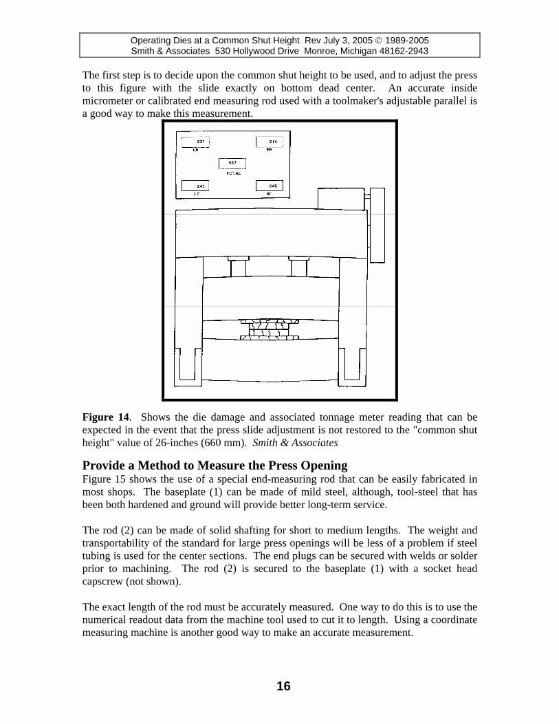
The first step is to decide upon the common shut height to be used, and to adjust the press to this figure with the slide exactly on bottom dead center. An accurate inside micrometer or calibrated end measuring rod used with a toolmaker's adjustable parallel is a good way to make this measurement.
Figure 14. Shows the die damage and associated tonnage meter reading that can be expected in the event that the press slide adjustment is not restored to the "common shut height" value of 26-inches (660 mm). Smith & Associates
Provide a Method to Measure the Press Opening Figure 15 shows the use of a special end-measuring rod that can be easily fabricated in most shops. The baseplate (1) can be made of mild steel, although, tool-steel that has been both hardened and ground will provide better long-term service. The rod (2) can be made of solid shafting for short to medium lengths. The weight and transportability of the standard for large press openings will be less of a problem if steel tubing is used for the center sections. The end plugs can be secured with welds or solder prior to machining. The rod (2) is secured to the baseplate (1) with a socket head capscrew (not shown). The exact length of the rod must be accurately measured. One way to do this is to use the numerical readout data from the machine tool used to cut it to length. Using a coordinate measuring machine is another good way to make an accurate measurement.
16

Operating Dies at a Common Shut Height Rev July 3, 2005 © 1989-2005 Smith & Associates 530 Hollywood Drive Monroe, Michigan 48162-2943
Figure 15. A simple means to determine actual press shut height accurately through the use of a simple, easy to fabricate measuring standard: (1) baseplate made of hardened tool steel; (2) end measuring rod calibrated in a coordinate measuring machine or machine tool having an accurate digital readout; (3) toolmaker's adjustable parallel or planer/shaper gage used to measure exact height above measuring rod to slide; (4) press slide; (5) press bolster. Smith & Associates
Figure 16. Taking an accurate measurement with a toolmakers adjustable parallel Smith & Associates
17

Operating Dies at a Common Shut Height Rev July 3, 2005 © 1989-2005 Smith & Associates 530 Hollywood Drive Monroe, Michigan 48162-2943
Making an Accurate Press Shut Height Measurement To take the measurement, a toolmaker's adjustable parallel or planer/shaper gage (3) is used to measure the space between the rod and the press slide as shown in Figure 16. The thickness of the adjustable parallel is simply measured with a micrometer and added to the length of the rod plus the thickness of the baseplate to obtain the total reading.
Figure 17. The measurement is added to the height of the precision end-measuring rod. Smith & Associates Sources of Error To obtain uniform measurements at different locations in the press opening, the press must be in good condition and the slide parallel with the bed. In fact, the measurement method illustrated in Figures 15 through 17 can also be used as part of the press inspection procedure. However, a dial indicator on a measuring rod is a more commonly accepted method for press inspections. The measuring standard shown in Figure 15 provides a precise means for calibrating shut height readout devices. Shut Height Indicator Adjustment Procedure To insure that all excess play has been drawn up in the bearings, the counterbalance air pressure should be raised to a higher setting than that required balancing the weight of the slide alone. The press must be exactly at 180 crankshaft degrees or exactly at bottom dead center. This should be verified with a dial indicator. The parallelism of the slide to the bed or bolster should be checked with a dial indicator attached to a test rod. Check all four corners and the middle as well. If the slide has a low place in the center due to overloading damage, this fact should be noted and corrected if possible. Keep a record of the readings for future reference. Press parallelism errors should be corrected before establishing the common press shut height figure and/or setting the readout device.
18

Operating Dies at a Common Shut Height Rev July 3, 2005 © 1989-2005 Smith & Associates 530 Hollywood Drive Monroe, Michigan 48162-2943
Accuracy of Adjustment Settings as close as 0.002-inch (0.0508 mm) can be maintained if the press is in good condition. The size of the machine is a factor. Slight differences in readings taken at the four corners should be averaged out. A record of the exact locations of the measurements should be maintained to assure repeatability when it is necessary to re-establish the setting. Setting Shut Height Readout Devices The use of the calibrated end-measuring rod shown in Figure 15 is an excellent way to both initially set, and verify the accuracy of shut height readout devices. Portable measuring equipment using the principle of laser interferometry can also be used. However, the end-measuring rod is rugged, low in cost, and its principle of operation is obvious to any mechanic. There are classic horror stories of wasted time and needless damage because someone thought setting a shut height indicator with a tape measure would provide sufficient accuracy. The use of simple procedures like the homemade end-measuring rod together with employee training can help avoid such problems.
Common Die Shut Height Adjustment Procedure
Once a common press shut height is established for a group of presses, all dies for these machines are then designed and built to this common dimension. As was just discussed, the dies will need fine-tuning of the actual measured shut heights if the die requires substantial tonnage when fully closed. The best procedure is to increase the die shut height from the nominal common value enough to obtain the required tonnage. If the required tonnage and the incremental deflection factor of the press are known, the amount of compensation can be easily calculated. Often, it is cost effective to modify existing dies to a common shut height by shimming or machining. If the die is equipped with a sub plate or parallels, any needed shims can be placed between these parts and a die shoe. Making Fine Adjustments There are several ways to determine the amount of fine adjustment to shut height needed to achieve correct tonnage values. In all cases, the method should depend on accurate measurement of both physical dimensions and operating forces. A Tonnage Monitor is Helpful Set the die and bottom carefully to the common shut height while observing the tonnage readings to avoid overload damage. Note the tonnage required producing a part at the shut height setting. Compare the tonnage reading with that, which is known to be correct for the process. Low readings are corrected by adding shims and high readings corrected by removing shims or re-machining.
19

Operating Dies at a Common Shut Height Rev July 3, 2005 © 1989-2005 Smith & Associates 530 Hollywood Drive Monroe, Michigan 48162-2943
Use the Press Shut Height Indicator If properly calibrated to give accurate information, a shut height indicator such as those shown in Figures 8 and 11 can provide the basis for quickly fine tuning shut heights. Any deviation from the nominal target value can then be corrected by milling or shimming. The amount of adjustment required to achieve the correct tonnage is exactly equal to the amount of change die shut height indicated on the shut height readout.
Maintaining a Common Shut Height
Once common shut heights are achieved for a group of dies, factors such as die wear and die rework can cause a drift or abrupt change from the established nominal value. Information about any rework in the toolroom that may have changed the shut height requires notice to the pressroom. Conspicuous warning tags and notices provided through production scheduling is advised. The Effect of Die Wear Die wear may result in the shut height becoming less than the normal value. For example, as the draw beads on a draw die blankholder wear, the increased pressure that is required to properly hold the blank is obtained by adjusting the slide for more tonnage which decreases shut height. This is also true of restriking and embossing dies. As the working surfaces wear away, increased pressure is needed to produce an acceptable part. This may be achieved by adding shims or using thicker shims. Quality considerations and available tonnage constraints place a limit compensating for die wear in this way can be permitted before die rework is required. Shim Adjustment May be required after Rework After dies are reworked, adjustment of the shims between the die shoe and buildup or milling of the die shoe(s) may again be necessary. Check the die in a tryout press with an exact way to measure shut height and tonnage prior to returning the die to production. This can help to avoid delays. The use of the measuring rod shown in Figure 16 is an excellent means to make a precise measurement in either a tryout or a production press. Reworked dies must be bottomed carefully since it must be assumed that a substantial change in shut height may have resulted.
Procedure for Transfer Presses Transfer presses that have a number of separate dies under a common slide require special consideration when adjusting the dies to a common shut height. The reason is that the bed of the transfer press, like other presses, deflects downward much like an archer's bow when stressed. The ram does much the same to a lesser extent depending upon where the loading is in relationship to the pitmans or plungers.
20

Operating Dies at a Common Shut Height Rev July 3, 2005 © 1989-2005 Smith & Associates 530 Hollywood Drive Monroe, Michigan 48162-2943
Figure 18 illustrates a transfer press (feed rails not shown) having four dies that are machined to the same shut height and just touching. Transfer presses have special shut height setting problems due to deflection of the press bed, slide and crown.
Figure 18. A transfer press with four dies all machined to the same height. Smith & Associates Figure 19 is an exaggerated view of the result of normal unavoidable bed and slide deflection. Because of this deflection when force is developed, additional tonnage may be required for the middle dies to close evenly. This excessive tonnage results in extreme compression of the other dies. The result is often reduced part quality due to coining marks, off angle flanges, burred trim edges and many other problems. Extra tonnage can be self-defeating because it results in even more press deflection. In extreme cases, dies can be broken, and sparks literally fly as illustrated in Figure 20. Avoiding Problems through Good Process Planning Often it is possible to design the process so that the dies that require high tonnages at the bottom of the press stroke are located directly under the press slide connections; that is the pitmans or guided plungers. This would include operations such as forming, embossing and coining. Dies that complete their work before full press closure such as trim, pierce, and flange dies are then located in the center of the press if possible. The bed deflection condition is not a problem since the flanging and trimming operations are completed before the press is completely closed and the high tonnage condition at bottom of stroke causes pronounced deflection in the machine.
21

Operating Dies at a Common Shut Height Rev July 3, 2005 © 1989-2005 Smith & Associates 530 Hollywood Drive Monroe, Michigan 48162-2943
Figure 19. An exaggerated view of the unavoidable bed and slide {deflection} in a large transfer press that requires compensation. Smith & Associates
Shim the Center Dies Another solution is to shim the dies in the middle of the press to compensate for press deflection. The tonnage for each die when operated alone in a conventional press at a common shut height should never exceed the total for all dies required to produce a good part in a transfer press. If the required tonnage is higher, energy is being wasted, excessive die wear may occur and quality may be compromised.
Visual Troubleshooting Techniques If die shut height fine-tuning is needed to achieve the correct total tonnage; one obvious step is to carefully examine the part(s) hit in each individual die for hard marks or other signs of over-bottoming. If setup or equalizer blocks are used, check to see if they may be imprinting the striking surfaces. Such a visual examination can provide the basis for a cut and try approach to establishing correct individual shut heights.
Figure 20. In extreme cases, deflection under loading results in extreme {compression} of the outer dies resulting in broken tooling. Smith & Associates
22

Operating Dies at a Common Shut Height Rev July 3, 2005 © 1989-2005 Smith & Associates 530 Hollywood Drive Monroe, Michigan 48162-2943
If an individual die in the transfer press is suspected of having too much shut height, remove that die and hit the other dies with parts in them while noting how much the total tonnage drops. If the tonnage exceeds the measured process tonnage for that die, reducing the die’s shut height the correct amount should solve the problem. In Die Force Monitoring in Transfer Presses Guesswork as to the fine-tuning of transfer press shut heights can be greatly lessened if the compression of a die member is measured with a bolt-on strain transducer or a strain gage. The test is done while the individual die is being tested in a conventional press. The bolt-on strain transducers designed for press tonnage meter applications are especially convenient because they can be installed easily while a die is in a storage area or in the press. These strain sensors are normally bolted to welded on pads that can be accurately positioned by means of a low-cost welding fixture. A good location is on the die parallels or some other member that is compressed in a known way during normal die functioning. The object is to adjust shut heights of the individual dies, which duplicate the strain measurements that were acceptable when the dies were operated in a tryout press. If the readings are given in terms of microstrain, which is parts per million of compression, actual loading of the member can be estimated from the cross sectional area and type of material by using simple engineering formulas. The strain transducers or strain links as they are also called are calibrated devices. They are capable of being removed from the dies and interchanged with repeatability of 2% or better. Transducer readout is accomplished with a portable battery powered instrument that also provides an analog output for chart recorder or oscillographic analysis. All of this specialized stress analysis equipment including calibration load cells is generally available from the manufacturers of tonnage meters.
Exchanging Dies between Presses at a Common Shut Height
In order to provide for manufacturing flexibility and possible equipment breakdowns, it is important to be able to run dies in more than one press. This is generally feasible in the case of presses built to a common design by the same manufacturer. As already stated, it is generally possible to operate cutting dies in a variety of presses with widely varying incremental deflection factors. This is possible because all of the work is done before the bottom of the press stroke. It is theoretically possible to do the same with dies that require large forces at the bottom of the press stroke if the appropriate shimming adjustment is done before dieset. Because of the degree of care required, this is seldom done.
23

Operating Dies at a Common Shut Height Rev July 3, 2005 © 1989-2005 Smith & Associates 530 Hollywood Drive Monroe, Michigan 48162-2943
Important Points to Remember Maintaining dies at a common shut height, or groups of shut heights, will provide benefits that go beyond improvements in stamping flexibility and setup time reduction. Die change damage avoidance and part quality improvement is an additional benefit to be realized from adopting this method. Adjusting dies to a common shut height may require more work than simply milling or shimming dies to a common figure. Even so, the procedure is simple. Never view the procedure as a black art requiring laborious die spotting and shimming in the press. Several important points are:
1. Always standardize the press shut height with the press empty and on bottom dead center.
2. As a rule, flange, pierce, and trim dies can have the same shut height as the press. 3. Presses must deflect to develop tonnage. 4. Dies that require substantial tonnages at the bottom of the press stroke may
require a slight increase in shut height to compensate for press deflection. 5. If both the press incremental deflection factor, and tonnage required at bottom of
stroke is known, the exact die shut height can be calculated. 6. Multi-die transfer presses require special consideration, but the procedure is still
straightforward. NOTES: _____________________________________________________ ________________________________________________________________ ________________________________________________________________ ________________________________________________________________ ________________________________________________________________ ________________________________________________________________ ________________________________________________________________ ________________________________________________________________ ________________________________________________________________
24