streacom db4 - lh6 heat pipe kit - user guide
TRANSCRIPT

DB4 LH6 KIT

2
Kit Contents
LH6 HeatpipeHeatsink MountUniversal BracketM3x6 ThumbscrewThermal Pad
x 3x 2x 2x 2x 2
Specification
Heat Pipe DiameterHeat Pipe Thermal RatingHeat Pipes Length
6mm 30-35W
Thumbnut
Kit Overview
Heat Sink Mount
M3x6 Thumbscrew
Universal Bracket
LH6 Heat Pipe
Introduction
The LH6 Kit for DB4 was designed to expand the CPU cooling from a single side panel to two side panels. It comprises of heat pipes, heak sink connectors, universal brackets and thermal pads/paste. When assembled correctly and with the appropriate environmental conditions, the total cooling performance can reach 105W* of heat dissipation. Whilst the stock DB4 heat pipes have been designed to work with virtually any motherboard layout, the LH6 will require a compatible CPU location and motherboard, see our system build guide for more details.

3
Prepare for Installation
If you are adding the optical drive to an existing build, remove the top panels and 2 of the side panels (the one currently used for CPU cooling and the adjacent one which will be used for the additional cooling) and any hardware which might interfere with the installation of the new heat pipes.
You will also need to remove and re-arrange two of the existing heat pipes from the standard cooler assembly. One will be removed and the others will be placed in different slots in the CPU and Heat Sink Mount. To so this you will need to remove the entire cooler assembly.
If you are in working on a new build, this step can be ignored as you will be able to fit the additional heat pipes during the initial assembly process.
4
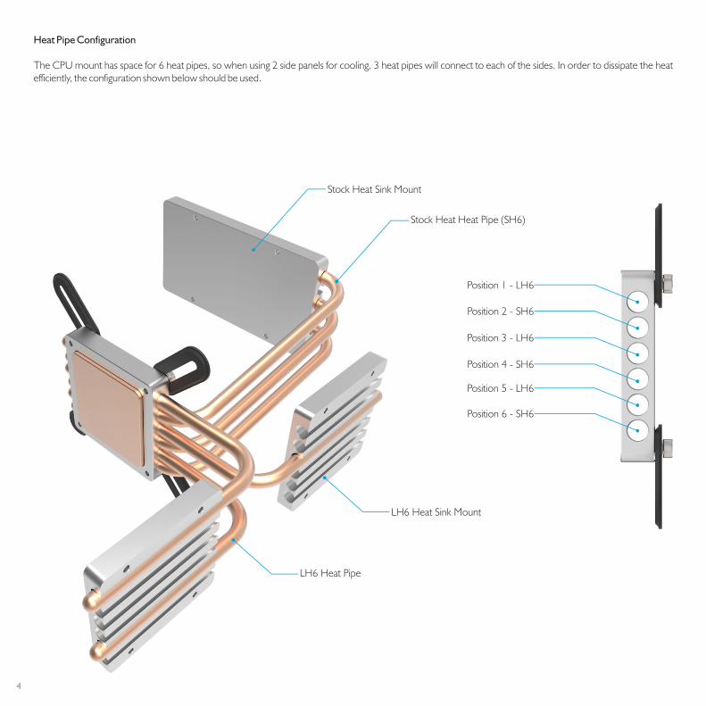
Heat Pipe Configuration
The CPU mount has space for 6 heat pipes, so when using 2 side panels for cooling, 3 heat pipes will connect to each of the sides. In order to dissipate the heat efficiently, the configuration shown below should be used.
Stock Heat Sink Mount
Stock Heat Heat Pipe (SH6)
LH6 Heat Sink Mount
LH6 Heat Pipe
Position 1 - LH6
Position 2 - SH6
Position 3 - LH6
Position 4 - SH6
Position 5 - LH6
Position 6 - SH6

5
Fitting the Heat Pipes
Replace the heat pipe assembly into the case. For the stock heat sink mount, follow the same procedure described in the DB4 user guide. For the LH4 heat pipes, fit the universal brackets but do not tighten the thumbnuts. You may also attached the M3x6 thumbscrews to the heat sink mounts, but again, to do not fully tighten them.
Warning! Make sure you peel away the protective flim on both sides of the thermal pad

6
Adjust and Secure the Heat Sink Mounts
The flex in the top panel will be used to operate the drive button, so the final step is to adjust the drive height as the gap will determine the amount of pressure required to operate the button. If you drive does not have a button, you will not need to adjust the height, just make sure its below the top panel.
To adjust the height, fit the top panel back onto the case and screw it down with all 4 screws. Carefully lift the drive until it is almost making contact with the top panel. Tighten all 4 of the drive cage screws to lock it against the motherboard tray, then push down in the centre of the top panel to test if the button gets depressed. If you feel the pressure required to active the button it too much, adjust the drive height upwards, if too little lower the drive.
Once you are happy with the button action, you can remove the top panel and finish the build, replacing all side panels and once finished, the top again.

7
Designed in Europe. Printed in China. Copyright © 2016. All Rights Reserved.