streamlined construction layout -...
TRANSCRIPT

Streamlined Construction Layout A Contractor’s Guide to Saving Money and Dramatically Reducing Layout TimeBy Cathi Hayes and Zack Crumal
+

constructrealityxyz.com
2+
Table of ContentsIntroduction
Basic Tools for Digital Layout
The Benefits of Total Station Layout
Case Study: Total Station Layout Saves Contractor $2,000 Per Week
Total Station Measurement Methods
Workflow Options
§ BIM/VDC Department
§ Production Layout
Case Study: Digital Layout Cuts Project Time in Half
Finding Your Competitive Edge
2
4
5
6
8
9
9
10
13
15

constructrealityxyz.com
3+
The building construction industry is valued at over $8 trillion globally with massive growth projected over the next 10 years. Despite the increasing demand, many contractors continue to struggle with low productivity and high waste, driven largely by unexpected rework and change orders. The complexity of buildings has increased, along with owner expectations to lower costs, accelerate turnaround and increase quality by adopting new processes, such as building information modeling (BIM) and digital workflows. Companies that want to compete and thrive in this new economy will be required to adapt.
Although many professionals think of BIM as a software or model, it’s really much more than that. BIM is a process with a model at its core. Many general contractors are aware of the benefits of using BIM to provide conflict resolution by identifying problems before they happen and to better facilitate building systems integration. However the benefits of BIM typically stop in the office. Rich digital models are often converted to 2D paper drawings for use in the field, where guesswork and manual layout processes can cause errors that might not become evident until later in the construction process. Additionally, on renovation or retrofit projects, the models themselves might contain errors since many models are developed from outdated and inaccurate as-built paper drawings.
IntroductionThese inaccuracies lead to problems in the field during construction, which drive up project costs, increase risks and even derail an entire project.
There is a better approach. In an ideal BIM workflow, the project team captures reality and informs the 3D model with highly accurate as-built point clouds. New design models are then created around the as-built point clouds, and construction layout points are added to the model. These points are then replicated on the jobsite using tools such as total stations and multistations (a new type of total station that has the added ability to capture laser scan data) to bring BIM to reality. During construction, as-built information is captured with high definition scanners and multistations. The point clouds and discrete measurement points are compared against the as-designed model to immediately identify deviations and head off expensive downstream coordination issues in the field. The result is reduced rework, more predictability and higher profitability.
For many contractors, the on-ramp to a full BIM workflow begins with digital layout. Let’s get started.
“The building construction industry is valued at over $8 trillion globally.”

constructrealityxyz.com
4+
The PrismA prism is used to reflect an infrared or red laser beam from the sensor or instrument. Prisms are most commonly used on a “prism pole” to give them height when measuring a point on the ground or floor.
Putting It All TogetherMost contractors use a 3D model to coordinate between disciplines – i.e. mechanical, structural and plumbing – so clashes do not occur in the field. This coordinated data can be used directly in the field by adding layout points either to the model or on 2D construction documents. The data is then handed off to the field controller, which is wirelessly connected to the sensor. The instrument is oriented to align the layout data with the jobsite. From there, contractors simply start “shooting points” to replicate the accuracy of BIM in the field.
Once work is in place, the layout points can be back checked to validate that the as-built (real world) matches the as-designed (model) with real time delta reporting. When deviations are identified, the as-built points can be brought back into to the model so the impact of the deviation can be evaluated by the project team and corrective actions can be planned if needed.
This insight is invaluable for contractors. It’s like having a crystal ball that predicts constructability issues and allows them to be corrected digitally before they become change orders and schedule delays.
The Field ControllerThis handheld device runs field software that controls the sensor or instrument. The type of controller depends on the user and application. BIM/VDC professionals who need a lightweight, short-range, off-the-shelf solution can use an iPad with construction layout apps. Production layout teams that need the rugged durability of a weather-proof controller with an extended range will want to use a sealed, extremely tough version of a Windows tablet enclosed in a ruggedized case so it can survive the harsh conditions on construction sites without getting broken. When using a tablet, look for models that feature an extra-long range Bluetooth connectivity of about 1,200 feet (although this range varies by controller) to remotely control instruments.
The Sensor/InstrumentUnlike the error-prone traditional methods of tape measures, string and plumb bobs, modern tools such as total stations and laser measurement devices enable contractors to measure angles and distances with precision. New technology such as 3D laser measurement tools can be used to streamline the layout of new interior construction such as mechanical, electrical and plumbing (MEP) and wall partitions. And recent innovations such as the multistation effortlessly integrate laser scanning capabilities with total station measurement for as-builting, construction layout and quality assurance checks.
Basic Tools for Digital LayoutThe first step is understanding the “lay of the land” – what are the parts and pieces, and how do they fit into your business. From there, it is much easier to strategically choose a starting point that will yield the best return on the investment.
A good place to begin is with an overview of the basic equipment used for digital layout from CAD or BIM and how they work together. Three key pieces of hardware used for digital construction layout are 1) the field controller, 2) the sensor or instrument and 3) the prism.

constructrealityxyz.com
5+
This combined model is used to identify constructability and building issues so solutions can be developed digitally before they become problems in reality on the construction site. Models are updated throughout the construction process with as-built field data to minimize unforeseen changes. Connecting BIM and digital layout is a win-win for the construction industry.
It’s a far cry from tape measures and strings, which leave a substantial amount of room for human error. Using total station technology makes jobs much easier and more efficient while providing the accuracy needed to successfully extend BIM from the office to the job site.
Total stations enable contractors to measure angles and distances with high accuracy for laying out new construction and as-builting existing construction using discrete points. Available in both manual and robotic options, they use a solid, well-proven technology that originated in distance measurement applications for the military. They have been used in surveying and engineering applications for many years. Now, these same solutions are being adapted for the construction industry.
Modern total stations built for construction applications are simple in design and easy to operate with minimal training. They allow the contractor to take very accurate, coordinated data directly from a model and digitally project it or replicate it on a jobsite for a “paint-by-numbers” installation, which accelerates both installation speed and accuracy by connecting the total station to the BIM process.
The Benefits of Total Station Layout
“Digitally project or replicate model data on a jobsite for a ‘paint-by-numbers’ installation.”
constructrealityxyz.com
6+
“Finding errors before the whole crew is onsite resulted in a foundation not lost, and I was able to reroute the footing crew to pour somewhere else,” Poortinga points out.
“Total dollars savings for the company was $6,000, plus I charged the builder $400 for the time spent on layout so the excavator could come back and fix the job.”
Accurate Layout – the First TimeWithout a total robotic station, a crew is typically sent out to do the footing with tape measures and strings. Once this this process is completed, the layout begins. “It’s generally around this time when we’d find a mistake in excavation or some other problem,” Poortinga says. “The guys would spend a good part of the day putting materials in the ground and then find out the footing wasn’t right so we wasted all that labor to get to that point. At $30 to $35 per hour pay plus insurance, etc., with a three- or four-person crew, it adds up quickly.”
Poortinga still finds mistakes using robotic total stations, but they are much easier to locate. “Very rarely do I even find mistakes now,” he says. “Out of 100 foundations I do, I’ll find one mistake. However, when you’re running tape measures and strings, you make mistakes every day.”
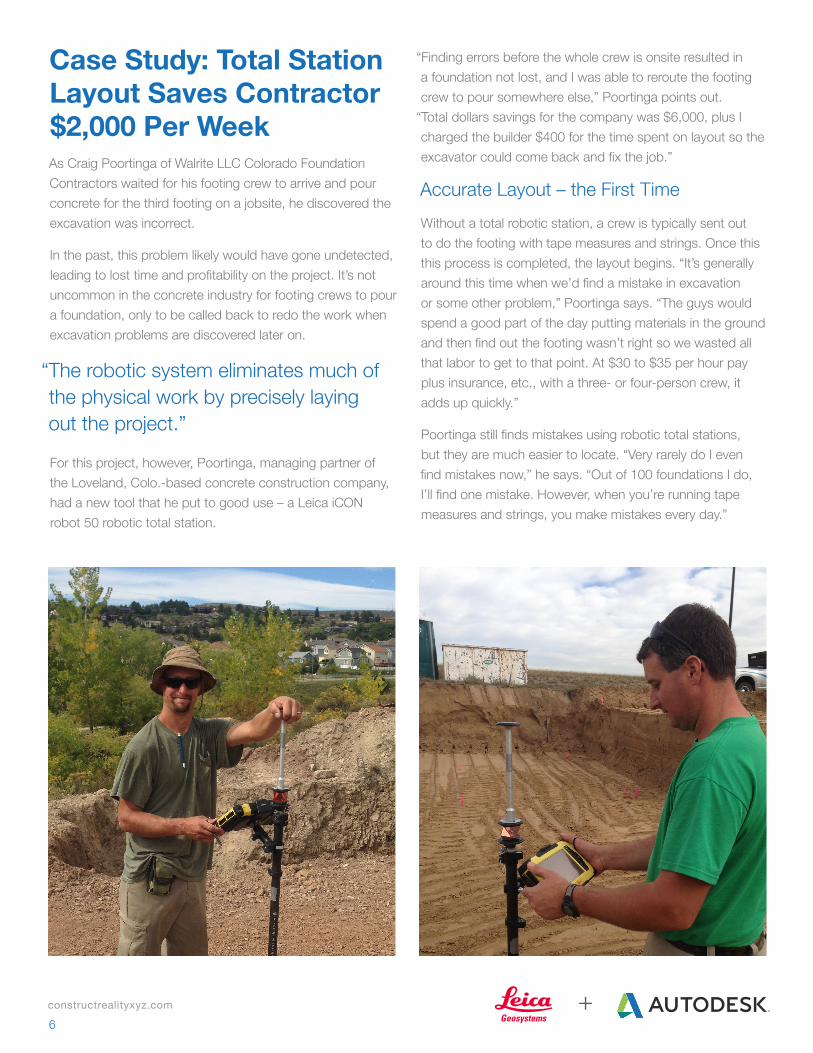
For this project, however, Poortinga, managing partner of the Loveland, Colo.-based concrete construction company, had a new tool that he put to good use – a Leica iCON robot 50 robotic total station.
Case Study: Total Station Layout Saves Contractor $2,000 Per WeekAs Craig Poortinga of Walrite LLC Colorado Foundation Contractors waited for his footing crew to arrive and pour concrete for the third footing on a jobsite, he discovered the excavation was incorrect.
In the past, this problem likely would have gone undetected, leading to lost time and profitability on the project. It’s not uncommon in the concrete industry for footing crews to pour a foundation, only to be called back to redo the work when excavation problems are discovered later on.
“The robotic system eliminates much of the physical work by precisely laying out the project.”

constructrealityxyz.com
7+
A More Efficient PourUsing the robotic total station technology has made jobs much easier and more efficient because now the crew can just build and stake without the extra steps of a layout using multiple crew members. “We build with no need to take apart because after layout, we see things that don’t fit,” Poortinga notes. “There are no stings to run or extra stakes to drive to layout. Any errors in the form layout are fixed prior to the final square. It’s much easier to do at this point than later. There’s less labor in moving and adjusting walls to achieve square and it’s also easier on the equipment.”
Concrete work is physically taxing on crew members, Poortinga says. The robotic system eliminates much of the physical work by precisely laying out the project. This translates to time saved on the jobsite. On simpler jobs, Poortinga estimates he has reduced the time of three crew members by 30 minutes each. For custom homes, a total of six man hours are saved with three crew members at an hour each. “Now add to that the ease of work and not having to tear apart and fix things, and we see a substantial savings,” Poortinga says.
A Boon to BusinessPoortinga says Walrite was able to achieve its return on investment within two months of using the robotic total station. The company is now on the profit margin side, saving about $300 to $400 per job in time, with an average of about a job per day. This adds up to a $1,500 to $2,000 savings per week.
“It’s a daily savings for me,” Poortinga says. “I’m not only saving on those parts of the job they don’t need to do anymore, but I can have them focus on other parts of the job that make it better. Instead of having three guys together to do a layout, one guy can do that while the other guys focus on the other details of the job.”
“Very rarely do I even find mistakes now. Out of 100 foundations I do, I’ll find one mistake. However, when you’re running tape measures and strings, you make mistakes every day.”

constructrealityxyz.com
8+
Total Station Measurement MethodsOnce you’ve decided to invest in total station layout, you’ve taken a good first step toward extending BIM to the field. But how do you know what type of total station you need?
Prism vs. Reflectorless MeasurementsThere are two ways the total station measures: using the traditional and still more common prism, or through reflectorless (red laser) technology.
With the prism method, the total station sends out invisible infrared waves that are reflected by the prism, which is typically attached to a pole. By measuring the prism’s position and knowing the precise angle and distance to that prism, the total station calculates the prism’s location or coordinates. Measurement to a typical 360 degree prism is roughly 5,000 feet (1500 meters), and measurement to a standard round prism can reach as far as 9,800 feet (3,000 meters). A 360 degree prism can face any direction, whereas a standard round prism only has one face that must look toward the total station.
Consider an application in which a stub-up needs to be located. The instrument is set up in the dirt off the building pad, and the person holding the prism pole, with the field controller attached, is guided by the field software to the correct location. The total station “tracks” the prism and continuously updates its position in the field software. When the exact position is reached with the prism, the field software displays a confirmation message.
The reflectorless method does not use a prism. Instead, it uses a visible red laser beam that allows the user to layout or measure points from any surface that is able to reflect it. The reach of the laser beam varies between instruments – it ranges from 1,300 feet to 6,500 feet (400 to 2,000 meters).
When determining which method to use, consider the location and logistics of the area being measured. A prism pole allows the instrument to reach places and measure points that can’t be achieved using a reflectorless method — for example, measuring around piles of building construction materials or other obstructions where a laser beam is unable to reach the desired point.
Reflectorless technology can also help make job sites safer. For example, if you need the length of a beam two stories high, you simply aim and shoot points at each end of the beam and you are done – no ladder or scaffolding required.
Manual vs. Robotic Total StationsManual and robotic total stations are available with both reflectorless and prism measurement. The biggest difference between these two types of total stations is that robotic total stations have a motor so they can be controlled remotely instead of manually.
The manual total station is a two-person operation. The instrument must be manually turned and the prism must be sighted each time. The electronic distance measurement (EDM) also must be triggered each time.
The robotic total station is a one-person operation. The station automatically follows the prism and is continuously measuring with the EDM.
When determining which total station and method is best for the job or operation, consider these points:
§ A robotic total station has a two-to-one labor ratio and enables the layout of 25 percent more points per day compared to a manual total station.
§ A tape measure and plumb bob requires two to three people and allows for the layout of about 200 points versus about 800 points with a robotic total station.
“A robotic total station enables the layout of 25 percent more points per day compared to a manual total station.”

constructrealityxyz.com
9+
If your project is working with highly accurate models in the office, that’s a good start for BIM. In many cases, however, the model data isn’t being used directly in the field. At best, this information gap drives up project risks; at worst, it results in errors and delays that can derail the entire construction schedule and budget and potentially lead to litigation. Fortunately, these problems can be easily solved by enriching the model with construction layout points. Once you’ve created models, or merged models from all disciplines and completed pre-construction coordination in Autodesk® Navisworks® Manage, the next step is to prepare the construction layout points in the model to be handed off to the field.
BIM/VDC Departments: Prepping Model Data for Field LayoutFor the BIM/VDC department, the way in which points are added to the model depends on the modeling software platform.
For example, layout points can be added directly in an Autodesk Revit, AutoCAD and/or Navisworks model using the Autodesk Point Layout plug-in. In Autodesk® Revit®, points can be added to any geometry or line types with automated capabilities for floor slabs, walls, wall track,
Workflow Optionsfoundations, ceilings and families. In AutoCAD®, there are also automated tools for MEP pipe & conduit stub ups/endpoints, hangers, sleeves, all line work types and tasks such as offsets and arrays of points, while in Autodesk® Navisworks® Simulate points can be easily added to all building components or lines automatically with the Mark Selections and Place Points tools.
The most critical element during the data prep process is establishing virtual control points in your CAD or BIM that exactly match your established control physically in the field. These control points allow the total station to be oriented on the jobsite so it can precisely locate and as-built points. The Autodesk® Point Layout plug-in has tools specifically designed to easily connect the virtual models to the correct jobsite or state plane coordinate system. The user just needs to select two locations in Revit or AutoCAD and enter the respective XYZ coordinates and save off the new Shared Coordinate system. Site Control points can be imported into the model and any additional Building control points can be created or added (grid intersection/offset from grid).
Once the control and layout points are all in place, the information needs to be stored in a way that will be easily accessible in the field. A popular solution is to use the Autodesk®BIM 360™Glue® add-in (within Navisworks,
Software such as Autodesk BIM 360 Layout iPad app helps bring the model to the field. Image courtesy of Holder Construction.

constructrealityxyz.com
10+
Revit, or AutoCAD) to publish a lightweight version of the constructability model to the Autodesk BIM 360 Glue web service, which can then be made accessible to the Autodesk BIM 360 Glue service and is accessible through the Autodesk®BIM 360™Field iPad app. A BIM 360 Glue administrator will need to set up the project and permissions for the team to access relevant project data. Once the BIM 360 Glue project with layout points is uploaded, the BIM 360 Layout iPad app will need to be synched with the BIM 360 Glue account for access to the relevant projects. From there, the entire coordinated project model with points can be downloaded to the iPad for local field use. (No Internet connection is required once the project has been downloaded.) BIM and Survey managers also have the ability to filter point information uploaded to the Glue service, by creating point sets or filtered point lists and assign these to users and notify them via email. This allows the field user to have an appropriate sized and located point list specific for them and the work to be completed. This Point set process also will keep track of progress of staked/completed progress when BIM 360 Layout point information is re-synced after field work. After field points are synced back to the BIM 360 Glue web service, Autodesk Point Layout users then can import and compare all point information directly from the field with no file transfer, just selecting the appropriate Glue project model.
BIM/VDC Departments: Getting Layout Points to the FieldArmed with your model and points for layout, QA/QC or as-builting/back-checking, the next step is to connect to the total station. Field hardware solutions that are integrated with the Autodesk BIM 360 Layout app, such as the Leica iCON robot 50, make this process easy. For a Known Point Setup, locate/ level the robot and tripod directly over one known control point location with a clear line of sight to the area you need to lay out or back check. Turn on the instrument and make sure the WiFi handle is in place and active.
From the BIM 360 Layout app, establish communications with the Leica iCON robot from iPad settings - Wifi and simply select the iCon device. Once a connection is made, BIM360 Layout has a Robot Setup wizard that will take you step by step from setup to search to backsight point
and completing setup. BIM360 Layout also has a resection setup option where the Robot can be positioned anywhere as long as at least two control points can be sighted/referenced (typically three or more). Check for errors in the x and y axis (note that z is not important for orientation) in the Deviation panel after setup is complete. The robot setup wizard also provides setup deviation information and allows for a Benchmark elevation routine. Your iCON robot now knows exactly where it is located and is ready to replicate the x, y and z accuracy of the model directly in the field.
Layout is simple. Sort and filter your point list by Nearest Point, Description, Elevation and many more options. Select the point from the model or list, and the BIM 360 Layout iPad app will guide you and the prism to the precise location. Hit collect to save a point (also can double tap collect to automatically go to Next Nearest point) and Mark the point and repeat the process until all points are staked in the field.
Production Layout: Prepping Model Data for Field LayoutFor construction layout professionals, the process begins in a similar way. First, determine which elements need construction layout points. Then identify at least two control points so the digital data can be oriented to the physical building in the field. The control points must be marked in the field and in the model so the coordinates can be easily aligned.
Projects such as residential concrete foundations can begin with paper drawings or 2D CAD drawings. If starting with paper, you can easily sketch the foundation directly in field software such as Leica iCON Build and add layout points directly in the field software. This type of digital layout is an excellent on-ramp into the BIM process. If you’re using a CAD file, layout points can be created using software such as MS Point Prep for highly accurate replication in the field.
“Field hardware solutions that are integrated with the Autodesk BIM 360 Layout app, such as the Leica iCON robot 50, make this process easy.”

constructrealityxyz.com
11+
For construction layout professionals, the process begins in a similar way. First, determine which elements need construction layout points. Then identify at least two control points so the digital data can be oriented to the physical building in the field. The control points must be marked in the field and in the model so the coordinates can be easily aligned.
Projects such as residential concrete foundations can begin with paper drawings or 2D CAD drawings. If starting with paper, you can easily sketch the foundation directly in field software such as Leica iCON Build and add layout points directly in the field software. This type of digital layout is an excellent on-ramp into the BIM process. If you’re using a CAD file, layout points can be created using software such as MS Point Prep for highly accurate replication in the field.
However, the most accurate way to add layout points is directly on a model using a tool such as Autodesk Point Layout or Leica Building Link. Points can be manually added, or the process can be automated by applying layout points to Revit families. For example, if layout points are added to a concrete pile cap family, all of the pile caps will automatically get layout points.
Production Layout: Prepping Model Data for Field Layout
Once the layout points are prepped, the data is ready to be handed to the field team. The next step in the data prep process is to export the points in an ASCII file format (.txt or .csv) and a plan underlay in DXF format. If your field team views reference models in the field, determine the viewer they are using and the file format they need for model viewing.
Once the DXF plan is imported, it will show up as an underlay to your points, which can be turned on or off as needed. For example, if you are laying out column locations, you would see a plan view of the columns with points at all the columns to identify your location in the field. This helps with orientation and provides context in the field.
Using high-accuracy tools such as total stations combined with intelligent software to apply construction layout points to the model and then transferring those points to the jobsite creates a “paint by number” plan for the contractors and installers. Enriching construction with high levels of accuracy streamlines processes, reduces the risk of errors, and improves predictability.

constructrealityxyz.com
12+
Production Layout: Getting Layout Points to the FieldOnce your BIM data has been prepped for field layout, you’re ready for the next step: taking it into the field. Armed with BIM layout points, plan underlays and reference models, you are now ready to shoot points on the jobsite that replicate the accuracy of BIM in the office.
In the field, the first step is to set up your instrument and make sure the construction site aligns with the model. Start by planning out where the total station will be positioned to shoot the layout points. The location should also be level, away from major construction traffic and provide a clear line of sight to at least two control points on the field controller and physically onsite.
After the total station tool is set up, the data collector needs to be connected to the instrument via wireless communication, such as WiFi or Bluetooth, so the two devices can communicate.
Next, it’s time to align model data with the onsite control points. This is accomplished by selecting the first control point on the model and measuring it in the field. A second control point on the model should then be selected and measured in the field to provide direction. Matching up the two control points from the model in the field will orient the instrument so you can flawlessly start shooting layout points with ease.
“Robotic total station layout is a natural extension of BIM and can increase your point layout productivity by an average of 25 percent.”
Once your instrument is oriented, select the first point to lay out. If laser/prismless mode (a visible red laser) is being used, the robot will automatically turn and indicate the exact point. If infrared laser with a prism is being used, the field controller software will guide you to the point with directions such as “left,” “right,” “towards,” “away,” etc., until you arrive at the exact point. Continue this process until all reachable points have been shot and marked.
To move the robot to the next location to continue shooting points, identify two points that will be used to reorient the instrument. These can be previously measured points, or you can shoot two new points exclusively for reorienting. Move the instrument to the new location, level and reorient by selecting the first control and measuring. Continue with a second control point. You should now be oriented and ready to lay out more points.
Robotic total station layout is a natural extension of BIM. It is a very efficient process that leverages highly accurate coordinated models for layout. Better data means better results. Robotic layout is also much more efficient than manual total station layout – one-person operation means that your labor is cut in half or more, which can increase your point layout productivity by an average of 25 percent.

constructrealityxyz.com
13+
For Sobcon Concrete, Inc., a full-service concrete contractor with clients all over Alabama, typical commercial projects once started with strings, tape measures, chalk lines and batter boards. “Our main work is forming and pouring concrete for foundations, retaining walls, columns and elevated slabs,” says Josh Hollingshead, Sobcon’s head project engineer. “Our crews do all of their own layout.”
These layouts – most of which are for major commercial projects – can take days to measure and process and are subject to human error and inaccuracies that can potentially cause expensive rework and delays. “Before, we would at least need the building corners set at a jobsite for us to even begin working. Then we would set the boards and start pulling distances with a tape measure and string,” Hollingshead says. “As our projects started getting bigger and covering larger areas, walking back and forth to pull those lines was becoming very time consuming, and the farther you are stretching the strings, the less accurate your measurements become.”
Case Study: Digital Layout Cuts Project Time in Half for Concrete Contractor
A Time-Saving SolutionA few months ago, a Leica Geosystems representative loaned Hollingshead a Leica iCON robot 50 robotic total station to try. Sobcon liked the new system so much that they have since purchased two.
With the new system, Sobcon was able to bring the architectural drawings that showed all of the unusual patterns and recesses in the sidewalks into tablets and lay out the points digitally. “Using the robots cut our layout time in half,” Hollingshead says.
One of the biggest benefits, Holingshead says, is the robot itself, which allows one crew member to complete the layout as opposed to having one person run the instrument while another is holding the reflector and setting the point.
Workflow has also improved. Previously, the crew’s foreman was responsible for getting drawings to the jobsite, and work could not begin until the entire project had been completely laid out. Now, the field data is coordinated with the office
Once the crew is onsite, the robot can be set up quickly and actual work can begin much faster.

constructrealityxyz.com
14+
A Fast Return on InvestmentNot only does this save time for crews in the field, but it also makes their job easier, which helped ease their transition to using robotic tools. “Instead of crews having to carry and flip through a set of drawings to find dimensions to incorporate into their batter board and string layout, they now have everything they need right there on the tablet,” Hollingshead says. “It saves a ton of time.”
It also saves a lot of money. “The system has paid for itself in two jobs,” Hollingshead says. “We bought two of them at the same time – one for each of the jobs we were working on. Now, it’s hard to keep everyone on our five crews happy because everyone wants to use them.”
Sobcon plans to purchase at least two additional robotic total stations in the near future so that more crews will have access to the technology. “These systems have made everything more efficient,” said Hollingshead, “which ultimately saves time and money for both our crews and our customers.”
“The system has paid for itself in two jobs.”

constructrealityxyz.com
15+
Finding Your Competitive EdgeToday’s construction industry is characterized by shorter building cycles, shrinking budgets and growing expectations for accurate data on demand. Although this situation presents numerous challenges for contractors, it also creates tremendous opportunities for firms that wish to differentiate themselves in an increasingly competitive market. Whether you’re actively embracing BIM or just looking for a way to increase efficiency and transparency on the jobsite, digital layout is a great place to start.
To learn more, visit www.constructrealityxyz.com.
About Leica GeosystemsWith close to 200 years of experience pioneering solutions to measure the world, Leica Geosystems products and services are trusted by professionals worldwide to help them capture, analyze, and present spatial information. Leica Geosystems is best known for its broad array of products that capture accurately, model quickly, analyze easily, and visualize and present spatial information. Leica Geosystems is part of Hexagon, a leading global provider of design, measurement and visualization technologies that enable customers to design, measure and position objects, and process and present data.
www.leica-geosystems.com | www.bimlearningcenter.com
About AutodeskAutodesk helps people imagine, design and create a better world. Everyone— from design professionals, engineers and architects to digital artists, students and hobbyists—uses Autodesk software to unlock their creativity and solve important challenges.
www.autodesk.com
Cathi Hayes is an architect, building information modeling (BIM) pioneer and strategy leader with more than 20 years of experience developing and implementing workflow improvements in various facets of the building design and construction industry. Early on in her career, she established Revit as an industry changing model-based design technology in the architectural design industry. She later served as strategic BIM manager for Autodesk. As BIM business manager for Leica Geosystems, Cathi focuses on helping building contractors achieve greater success in BIM through the adoption of leading-edge hardware and software solutions that make it easy to move from 2D to 3D workflows and extend the value of BIM into the field. She can be reached at [email protected].
Zach Crumal works for Autodesk on the product teams for Autodesk Point Layout and BIM360 Layout iOS mobile app. He came to Autodesk through the acquisition of Get The Point in 2013, and has been helping create tools for construction and MEP firms across the globe utilizing BIM, model based layout and total stations. He has worked as a BIM Specialist for construction firms in Colorado and currently lives in Denver. He has his B.A in Architecture from the University of Colorado at Boulder.
Autodesk, the Autodesk logo, AutoCAD, BIM 360, Navisworks, and Revit are registered trademarks or trademarks of Autodesk, Inc., and/or its subsidiaries and/or affiliates in the USA and/or other countries. All other brand names, product names, or trademarks belong to their respective holders. Both Autodesk and Leica Geosystems reserve the right to alter product and services offerings, and specifications and pricing at any time without notice, and are not responsible for typographical or graphical errors that may appear in this document. ©2015 Autodesk, Inc. and Leica Geosystems, Inc. All rights reserved.
About the Authors
Cathi HayesBIM Strategy and Business Development Director, Leica Geosystems
Zack CrumalSubject Matter Expert, Autodesk