streampro adcp operation manual - otronix.com · streampro adcp operation manual p/n 95b-6003-00...
TRANSCRIPT
StreamPro ADCP Operation Manual
Click http://www.rdinstruments.com/smartlink/sp/index.shtml to get the latest documentation changes, Field Service Bulletins, FAQ's, and Product News!
P/N 95B-6003-00 (February 2008)

Table of Contents 1 Introduction....................................................................................................................................... 1
1.1 How to Contact Teledyne RD Instruments ..........................................................................................1 1.2 Notice of Compliance..........................................................................................................................2
1.2.1 Date of Manufacture ...........................................................................................................................2 1.2.2 Environmental Friendly Use Period (EFUP)........................................................................................2 1.2.3 WEEE .................................................................................................................................................2 1.2.4 CE.......................................................................................................................................................2 1.2.5 Material Disclosure Table ...................................................................................................................3
1.3 Conventions Used in Manuals ............................................................................................................4 2 StreamPro Overview......................................................................................................................... 5
2.1 Inventory .............................................................................................................................................5 2.2 Visual Inspection of the StreamPro.....................................................................................................5 2.3 StreamPro Overview...........................................................................................................................6
3 StreamPro Care................................................................................................................................. 7 3.1 General Handling Guidelines ..............................................................................................................7 3.2 Assembly Guidelines ..........................................................................................................................7 3.3 Deployment Guidelines.......................................................................................................................7
4 StreamPro Assembly........................................................................................................................ 8 5 StreamPro Communications Setup .............................................................................................. 11
5.1 Creating a Bluetooth Shortcut ...........................................................................................................11 5.2 Establish a Bluetooth Connection .....................................................................................................12
6 Testing Your StreamPro ADCP ..................................................................................................... 14 7 Troubleshooting ............................................................................................................................. 15 8 StreamPro Maintenance................................................................................................................. 17
8.1 Spare Parts .......................................................................................................................................17 8.2 Transducer Assembly .......................................................................................................................19 8.3 Solar Shield Removal .......................................................................................................................20 8.4 Battery Replacement ........................................................................................................................20 8.5 Electronic Housing Cover Plate Removal .........................................................................................22 8.6 StreamPro Re-assembly...................................................................................................................23
8.6.1 Cover Plate O-Ring Inspection and Replacement.............................................................................23 8.6.2 Battery Compartment O-Ring Inspection & Replacement .................................................................24 8.6.3 Electronic Housing Cover Plate Replacement ..................................................................................25
8.7 Solar Shield Replacement.................................................................................................................26 8.8 Desiccant Bags .................................................................................................................................26 8.9 Storage and Shipping Maintenance ..................................................................................................27
8.9.1 Removal of Biofouling .......................................................................................................................27 8.9.2 Transducer Head Inspection .............................................................................................................28 8.9.3 Final Storage.....................................................................................................................................28 8.9.4 Shipping Preparation ........................................................................................................................30
8.10 Returning StreamPro ADCPs to TRDI for Service ............................................................................31 8.10.1 Domestic Shipments .........................................................................................................................31 8.10.2 International Shipments ....................................................................................................................32
9 StreamPro Commands................................................................................................................... 34 9.1 Data Communication and Command Format....................................................................................34
9.1.1 Command Input Processing..............................................................................................................34 9.1.2 Data Output Processing....................................................................................................................35
9.2 Firmware Upgrades ..........................................................................................................................36 9.3 Feature Upgrades .............................................................................................................................40
9.3.1 How to Install the Long Range Feature Upgrade ..............................................................................41 9.4 Command Descriptions.....................................................................................................................44
9.4.1 Miscellaneous Commands................................................................................................................44 ? – Help Menus.................................................................................................................................44
9.4.2 Control System Commands ..............................................................................................................45 CK - Keep Parameters......................................................................................................................45 CR – Retrieve Parameters ................................................................................................................45 CS – Start Pinging (Go) ....................................................................................................................46
9.4.3 Environmental Commands................................................................................................................47 EC - Speed of Sound ........................................................................................................................47 ES – Salinity......................................................................................................................................47 ET - Temperature..............................................................................................................................48 EX – Coordinate Transformation.......................................................................................................48 EZ - Sensor Source ..........................................................................................................................49
9.4.4 Performance and Testing Commands ..............................................................................................50 PS – Display System Parameters .....................................................................................................50 PT - Built-In Tests .............................................................................................................................51 PT0 - Help.........................................................................................................................................51 PT2 – Show Sensors ........................................................................................................................51 PT3 - Receive Path...........................................................................................................................52
9.4.5 Timing Commands............................................................................................................................53 TS – Set Real-Time Clock.................................................................................................................53
9.4.6 Water Profiling Commands ...............................................................................................................54 WF – Blank after Transmit ................................................................................................................54 WN – Number of Bins .......................................................................................................................54 WS – Depth Cell Size .......................................................................................................................55
10 Introduction to Output Data Format ............................................................................................. 56 10.1 Header Data Format .........................................................................................................................58 10.2 Fixed Leader Data Format ................................................................................................................60 10.3 Variable Leader Data Format............................................................................................................66 10.4 Velocity Data Format ........................................................................................................................72 10.5 Correlation Magnitude, Echo Intensity, and Percent-Good Data Format ..........................................74 10.6 Binary Bottom-Track Data Format ....................................................................................................78 10.7 Binary Reserved BIT Data Format ....................................................................................................81 10.8 Binary Checksum Data Format .........................................................................................................82
11 How to Decode an ADCP Ensemble ............................................................................................. 83 11.1 Rules for the PD0 Data Format.........................................................................................................83 11.2 Recommended Data Decoding Sequence for PD0 Data Format ......................................................84 11.3 Pseudo-Code for Decoding PD0 Ensemble Data .............................................................................84 11.4 Example Code for Decoding Ensembles ..........................................................................................85
12 Specifications ................................................................................................................................. 90 13 Glossary .......................................................................................................................................... 98
List of Figures Figure 1. StreamPro Overview ....................................................................................................... 6 Figure 2. StreamPro Assembly – Boom in Extended Position ........................................................ 8 Figure 3. StreamPro Assembly – Boom in in-hull Position.............................................................. 8 Figure 4. Transducer Adjustment for In-Hull ................................................................................. 10 Figure 5. Bluetooth Shortcut to the StreamPro ADCP .................................................................. 12 Figure 6. Testing the Bluetooth Connection.................................................................................. 13 Figure 7. Testing the StreamPro................................................................................................... 14 Figure 8. StreamPro Electronic Housing Assembly ...................................................................... 18 Figure 9. StreamPro Transducer Assembly .................................................................................. 19 Figure 10. Transducer Cable Connector ........................................................................................ 19 Figure 11. M6 Standoff Bolt on Electronic Housing Cover Plate..................................................... 20 Figure 12. StreamPro Battery Replacement ................................................................................... 22 Figure 13. Closing the Battery Cover ............................................................................................. 22 Figure 14. StreamPro Shipping Case ............................................................................................. 29 Figure 15. Create a New Folder on the iPAQ ................................................................................. 36 Figure 16. File Explorer.................................................................................................................. 37 Figure 17. WinCEFlash Program.................................................................................................... 38 Figure 18. WinCEFlash Done Message ......................................................................................... 38 Figure 19. Exiting the WinCEFlash Program .................................................................................. 39 Figure 20. Capture PS0 Information to File .................................................................................... 41 Figure 21. Capture PS0 Information to File Results ....................................................................... 41 Figure 22. Use File Explorer to Run the Feature Upgrade ............................................................. 42 Figure 23. Feature Enable Program............................................................................................... 43 Figure 24. PD0 Standard Output Data Buffer Format ..................................................................... 57 Figure 25. Binary Header Data Format........................................................................................... 58 Figure 26. Fixed Leader Data Format ............................................................................................ 61 Figure 27. Variable Leader Data Format ........................................................................................ 67 Figure 28. Velocity Data Format ..................................................................................................... 72 Figure 29. Binary Correlation Magnitude, Echo Intensity, and Percent-Good Data Format ............ 74 Figure 30. Binary Bottom-Track Data Format ................................................................................. 79 Figure 31. Binary Reserved BIT Data Format................................................................................. 81 Figure 32. Binary Checksum Data Format ..................................................................................... 82 Figure 33. Outline Installation Drawing – Sheet 1 of 3 ................................................................... 92 Figure 34. Outline Installation Drawing – Sheet 2 of 3 ................................................................... 93 Figure 35. Outline Installation Drawing – Sheet 3 of 3 ................................................................... 94
List of Tables Table 1: Toxic or Hazardous Substances and Elements Contained in Product ............................. 3 Table 2: Visual Inspection Criteria................................................................................................. 5 Table 3: Troubleshooting the StreamPro ADCP .......................................................................... 16 Table 4: Spare Parts ................................................................................................................... 17 Table 5: Retrieve Parameters ..................................................................................................... 45 Table 6: Coordinate Transformation Processing Flags................................................................ 48 Table 7: Sensor Source Switch Settings ..................................................................................... 49 Table 8: Data ID Codes............................................................................................................... 56 Table 9: Header Data Format...................................................................................................... 59 Table 10: Fixed Leader Data Format ............................................................................................ 62 Table 11: Variable Leader Data Format ........................................................................................ 68 Table 12: Velocity Data Format ..................................................................................................... 73 Table 13: Correlation Magnitude Data Format .............................................................................. 75 Table 14: Echo Intensity Data Format........................................................................................... 75 Table 15: Percent-Good Data Format ........................................................................................... 77 Table 16: Bottom-Track Data Format ............................................................................................ 80 Table 17: Reserved for TRDI Format ............................................................................................ 81 Table 18: Checksum Data Format ................................................................................................ 82 Table 19: Common Data Format IDs............................................................................................. 83 Table 20: Velocity Profiling Specifications ..................................................................................... 90 Table 21: Transducer Specifications ............................................................................................. 90 Table 22: Standard Sensors Specifications................................................................................... 90 Table 23: Communications Specifications..................................................................................... 90 Table 24: StreamPro ADCP Construction Specifications............................................................... 90 Table 25: StreamPro ADCP Power Specifications......................................................................... 91 Table 26: StreamPro ADCP Physical Properties ........................................................................... 91 Table 27: StreamPro ADCP Environmental Specifications ............................................................ 95 Table 28: iPAQ Pocket PC Specifications ..................................................................................... 95 Table 29: iPAQ Pocket PC Battery Specifications ......................................................................... 96 Table 30: iPAQ Pocket PC Bluetooth Specifications ..................................................................... 96 Table 31: Software Requirements................................................................................................. 97
StreamPro ADCP Operation Manual
P/N 95B-6003-00 (February 2008) page 1
StreamPro ADCP Operation Manual
1 Introduction Thank you for purchasing the Teledyne RD Instruments (TRDI) StreamPro Acoustic Doppler Current Profiler (ADCP). The StreamPro ADCP Opera-tion Manual contains detailed information on the StreamPro ADCP includ-ing assembly, maintenance items, testing, commands, and Output Data Format.
1.1 How to Contact Teledyne RD Instruments If you have technical issues or questions involving a specific application or deployment with your instrument, contact our Field Service group: Teledyne RD Instruments Teledyne RD Instruments Europe
14020 Stowe Drive Poway, California 92064
2A Les Nertieres 5 Avenue Hector Pintus 06610 La Gaude, France
Phone +1 (858) 842-2600 Phone +33(0) 492-110-930
FAX +1 (858) 842-2822 FAX +33(0) 492-110-931
Sales – [email protected] Sales – [email protected]
Field Service – [email protected] Field Service – [email protected]
Customer Service Administration – [email protected] Web: http://www.rdinstruments.com
24/7 Technical Support +1 (858) 842-2700

StreamPro ADCP Operation Manual
page 2 Teledyne RD Instruments
1.2 Notice of Compliance
1.2.1 Date of Manufacture China RoHS requires that all Electrical and Electronic Products are marked with a Date of Manufacture. This is the starting point for the Environmental Friendly Use Period, described below.
1.2.2 Environmental Friendly Use Period (EFUP) Per SJ/T 11364-2006 – Product Marking, the EFUP is defined as the time in years in which hazardous/toxic substances within Electrical and Electronic Products (EIP) will not, under normal operating conditions, leak out of the Product, or the Product will not change in such a way as to cause severe en-vironmental pollution, injury to health, or great damage to property. TRDI has determined the Environmental Friendly Use Period shall be Ten (10) years.
The purpose of the marking is to assist in determining the restricted sub-stance content, recyclability, and environmental protection use period of our covered products, as required in Chinese law, and does not reflect in any way the safety, quality, or warranty associated with these TRDI products.
Some homogenous substance within the EIP contains toxic or hazardous sub-stances or elements above the requirements listed in SJ/T 11363-2006. These substances are identified in Table 1 on page 2.
1.2.3 WEEE The mark shown to the left is in compliance with the Waste Electrical and Elec-tronic Equipment Directive 2002/96/EC (WEEE).
This symbol indicates the requirement NOT to dispose the equipment as un-sorted municipal waste, but use the return and collection systems according to local law or return to one of the TRDI facilities below.
Teledyne RD Instruments USA 14020 Stowe Drive Poway, California 92064
Teledyne RD Instruments Europe2A Les Nertieres 5 Avenue Hector Pintus 06610 La Gaude, France
Teledyne RD Technologies 1206 Holiday Inn Business Building899 Dongfang Road, Pu Dong Shanghai 20122 China
1.2.4 CE
This product complies with the Electromagnetic Compatibility Directive 89/336/EEC, 92/31/EEC. The following Standards were used to verify compli-ance with the directives: EN 61326(1997), A1(1998), A2(2001) – Class “A” Ra-diated Emissions.
StreamPro ADCP Operation Manual
P/N 95B-6003-00 (February 2008) page 3
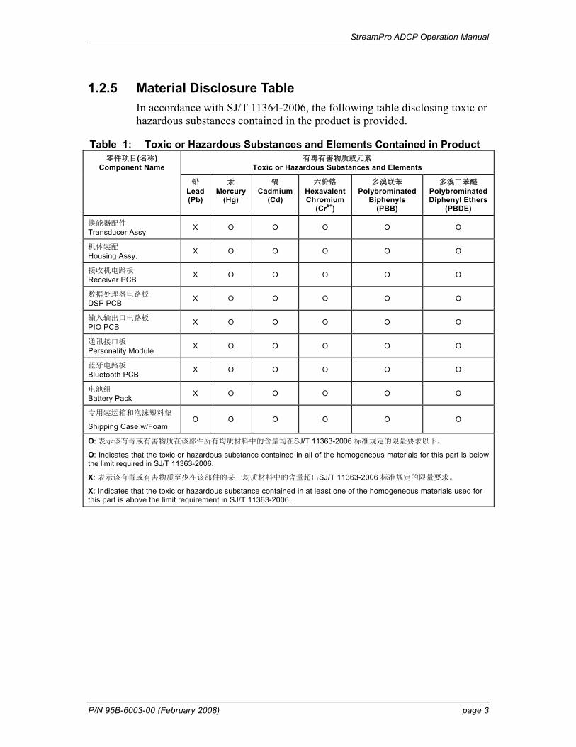
1.2.5 Material Disclosure Table In accordance with SJ/T 11364-2006, the following table disclosing toxic or hazardous substances contained in the product is provided.
Table 1: Toxic or Hazardous Substances and Elements Contained in Product 有毒有害物质或元素
Toxic or Hazardous Substances and Elements 零件项目(名称)
Component Name
铅 Lead (Pb)
汞 Mercury
(Hg)
镉 Cadmium
(Cd)
六价铬 HexavalentChromium
(Cr6+)
多溴联苯 Polybrominated
Biphenyls (PBB)
多溴二苯醚 PolybrominatedDiphenyl Ethers
(PBDE)
换能器配件 Transducer Assy. X O O O O O
机体装配 Housing Assy. X O O O O O
接收机电路板 Receiver PCB X O O O O O
数据处理器电路板 DSP PCB X O O O O O
输入输出口电路板 PIO PCB X O O O O O
通讯接口板 Personality Module X O O O O O
蓝牙电路板 Bluetooth PCB X O O O O O
电池组 Battery Pack X O O O O O
专用装运箱和泡沫塑料垫
Shipping Case w/Foam O O O O O O
O: 表示该有毒或有害物质在该部件所有均质材料中的含量均在SJ/T 11363-2006 标准规定的限量要求以下。
O: Indicates that the toxic or hazardous substance contained in all of the homogeneous materials for this part is below the limit required in SJ/T 11363-2006.
X: 表示该有毒或有害物质至少在该部件的某一均质材料中的含量超出SJ/T 11363-2006 标准规定的限量要求。
X: Indicates that the toxic or hazardous substance contained in at least one of the homogeneous materials used for this part is above the limit requirement in SJ/T 11363-2006.
StreamPro ADCP Operation Manual
page 4 Teledyne RD Instruments
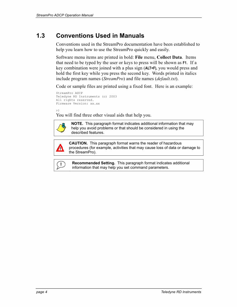
1.3 Conventions Used in Manuals Conventions used in the StreamPro documentation have been established to help you learn how to use the StreamPro quickly and easily.
Software menu items are printed in bold: File menu, Collect Data. Items that need to be typed by the user or keys to press will be shown as F1. If a key combination were joined with a plus sign (ALT+F), you would press and hold the first key while you press the second key. Words printed in italics include program names (StreamPro) and file names (default.txt).
Code or sample files are printed using a fixed font. Here is an example: StreamPro ADCP Teledyne RD Instruments (c) 2003 All rights reserved. Firmware Version: xx.xx >?
You will find three other visual aids that help you.
NOTE. This paragraph format indicates additional information that may help you avoid problems or that should be considered in using the described features.
CAUTION. This paragraph format warns the reader of hazardous procedures (for example, activities that may cause loss of data or damage to the StreamPro).
Recommended Setting. This paragraph format indicates additional information that may help you set command parameters.
StreamPro ADCP Operation Manual
P/N 95B-6003-00 (February 2008) page 5
2 StreamPro Overview The StreamPro ADCP is designed to measure real-time velocity and dis-charge measurements in shallow streams. The StreamPro system consists of a transducer, electronics housing, float, and software.
2.1 Inventory You should have the following items
• StreamPro transducer and cable assembly • StreamPro electronics housing and mounting plate • StreamPro float • StreamPro towing harness • StreamPro Quick Start Guide • StreamPro Discharge Measurement Summary card • StreamPro software CD • StreamPro ADCP documentation CD • iPAQ Pocket PC • Tools and Spare Parts kit • Eight AA batteries • Shipping crate (please save all foam for reshipping use)
If you ordered the Section-By-Section software upgrade, the following items will be added.
• Section-By-Section key code sheet • Section-By-Section User’s Guide • Section-By-Section Discharge Measurement Summary card
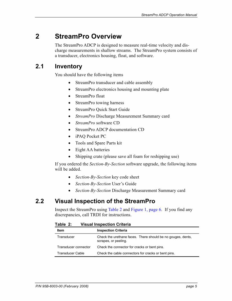
2.2 Visual Inspection of the StreamPro Inspect the StreamPro using Table 2 and Figure 1, page 6. If you find any discrepancies, call TRDI for instructions.
Table 2: Visual Inspection Criteria Item Inspection Criteria
Transducer Check the urethane faces. There should be no gouges, dents, scrapes, or peeling.
Transducer connector Check the connector for cracks or bent pins.
Transducer Cable Check the cable connectors for cracks or bent pins.
StreamPro ADCP Operation Manual
page 6 Teledyne RD Instruments
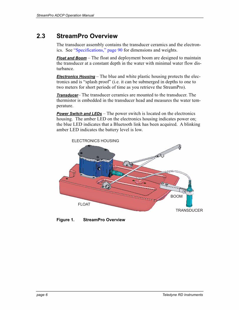
2.3 StreamPro Overview The transducer assembly contains the transducer ceramics and the electron-ics. See “Specifications,” page 90 for dimensions and weights.
Float and Boom – The float and deployment boom are designed to maintain the transducer at a constant depth in the water with minimal water flow dis-turbance.
Electronics Housing – The blue and white plastic housing protects the elec-tronics and is “splash proof” (i.e. it can be submerged in depths to one to two meters for short periods of time as you retrieve the StreamPro).
Transducer– The transducer ceramics are mounted to the transducer. The thermistor is embedded in the transducer head and measures the water tem-perature.
Power Switch and LEDs – The power switch is located on the electronics housing. The amber LED on the electronics housing indicates power on; the blue LED indicates that a Bluetooth link has been acquired. A blinking amber LED indicates the battery level is low.
ELECTRONICS HOUSING
BOOM
TRANSDUCERFLOAT
Figure 1. StreamPro Overview

StreamPro ADCP Operation Manual
P/N 95B-6003-00 (February 2008) page 7
3 StreamPro Care This section contains a list of items you should be aware of every time you handle, use, or deploy your StreamPro. Please refer to this list often.
NOTE. TDRI’s SmartLink has very useful information including links to the documentation, software, and firmware. It is good to check it periodically for updated information. http://rdinstruments.com/smartlink/sp/
3.1 General Handling Guidelines • Never set the transducer on a hard or rough surface. The ure-
thane faces may be damaged.
• Do not expose the transducer faces to prolonged sunlight. The urethane faces may develop cracks. Cover the transducer faces on the StreamPro if it will be exposed to sunlight.
• Do not store the StreamPro ADCP in extreme temperatures (see Table 27, page 95). The urethane faces may be damaged.
• Do not lift or support a StreamPro by the external cable. The connector or cable will break.
• Do not leave the batteries inside the StreamPro ADCP for ex-tended periods. The batteries may leak, causing damage to the electronics. Store the batteries in a cool, dry location (0 to 21 degrees C).
3.2 Assembly Guidelines • Read the Maintenance section for details on StreamPro assembly.
Loose, missing, stripped hardware, or damaged O-rings can lead to water ingress and damage to the StreamPro ADCP.
• Do not connect or disconnect the transducer cable with power applied. When you connect the cable with power applied, you may see a small spark. The connector pins may become pitted and worn.
3.3 Deployment Guidelines • Read the StreamPro Quick Start Guide. This guide will help
you learn how to use the StreamPro.
• Bluetooth communications will not work if the internal tem-perature of the StreamPro ADCP is above 50 degrees C. If you are having communication problems and are operating in a hot, sunny climate, allow the StreamPro ADCP to cool before continuing.
StreamPro ADCP Operation Manual
page 8 Teledyne RD Instruments
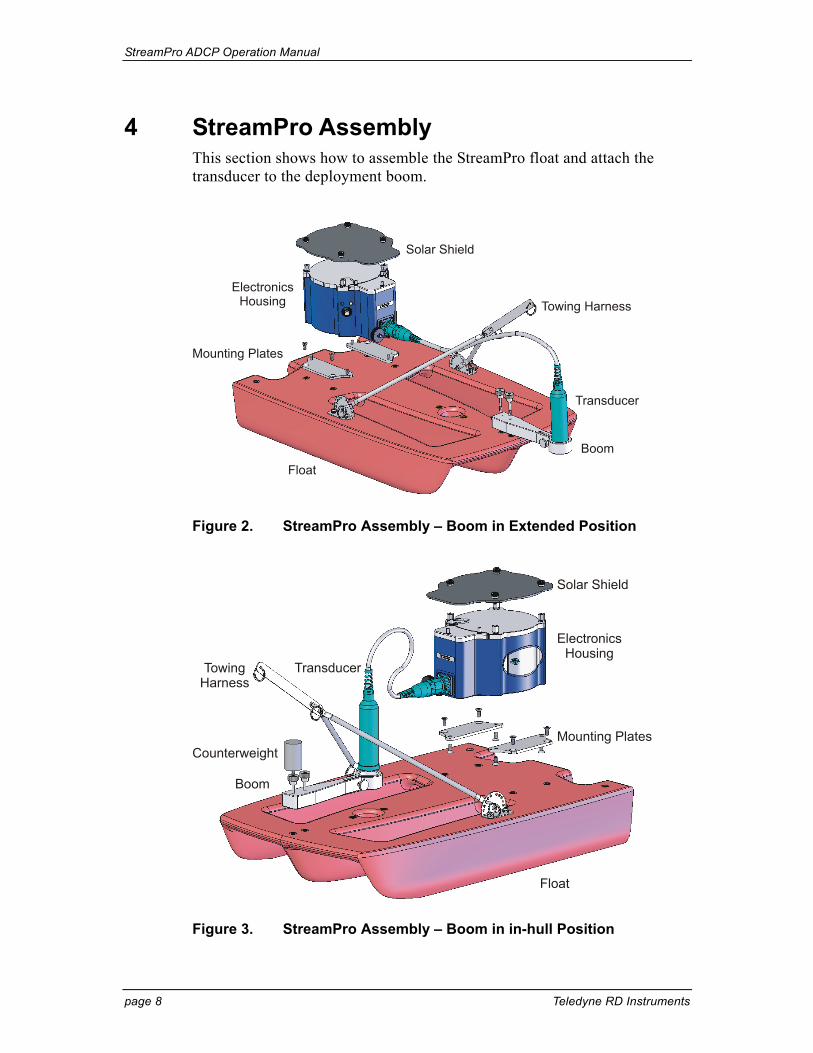
4 StreamPro Assembly This section shows how to assemble the StreamPro float and attach the transducer to the deployment boom.
Solar Shield
ElectronicsHousing
Mounting Plates
Float
Boom
Transducer
Towing Harness
Figure 2. StreamPro Assembly – Boom in Extended Position
Solar Shield
ElectronicsHousing
CounterweightMounting Plates
Float
Boom
TransducerTowingHarness
Figure 3. StreamPro Assembly – Boom in in-hull Position
StreamPro ADCP Operation Manual
P/N 95B-6003-00 (February 2008) page 9
Attach the Electronic Housing to the Float
Attach the mounting plates to the electronic housing using the four flat head screws. Attach the mounting plates to the float using the four flat head screws. The I/O cable connector should be facing toward the front of the float.
NOTE. The electronic housing may be pre-installed.
Attach the Solar Shield to the Electronic Housing
Attach the solar shield to the standoff bolts on the electric housing cover plate using the attached thumbscrews. Tighten the thumbscrews “finger tight”. Do not over tighten.
CAUTION. It is important to only gently finger tighten the sunshield screws when placing the sunshield back on the electronic housing M6 bolts. Should any movement occur on the M6 bolts due to over tightening the sun shield screws, the Loctite seal will be broken, and thus allowing the M6 bolts to subsequently become loose (see “Solar Shield Replacement,” page 26 for details).
Assemble the Boom
a. Loosen the thumbscrew on the transducer clamp. Feed the transducer cable up through the bottom of the clamp.
b. Attach the transducer cable to the electronics housing.
c. Attach the boom to the float using the supplied thumbscrews. If you mounted the boom in the in-hull position, attach the counterweight to the front thumbscrew. This helps balance the float.
StreamPro Transducer Adjustment
a. Locate the embossed number three on the edge of the transducer. This identifies Beam 3. Rotate the transducer so that Beam 3 is forward and at a 45 degree angle to the float.
NOTE. Beam 3 should remain pointed forward and at the 45-degrees angle for both the in-hull and extended positions.
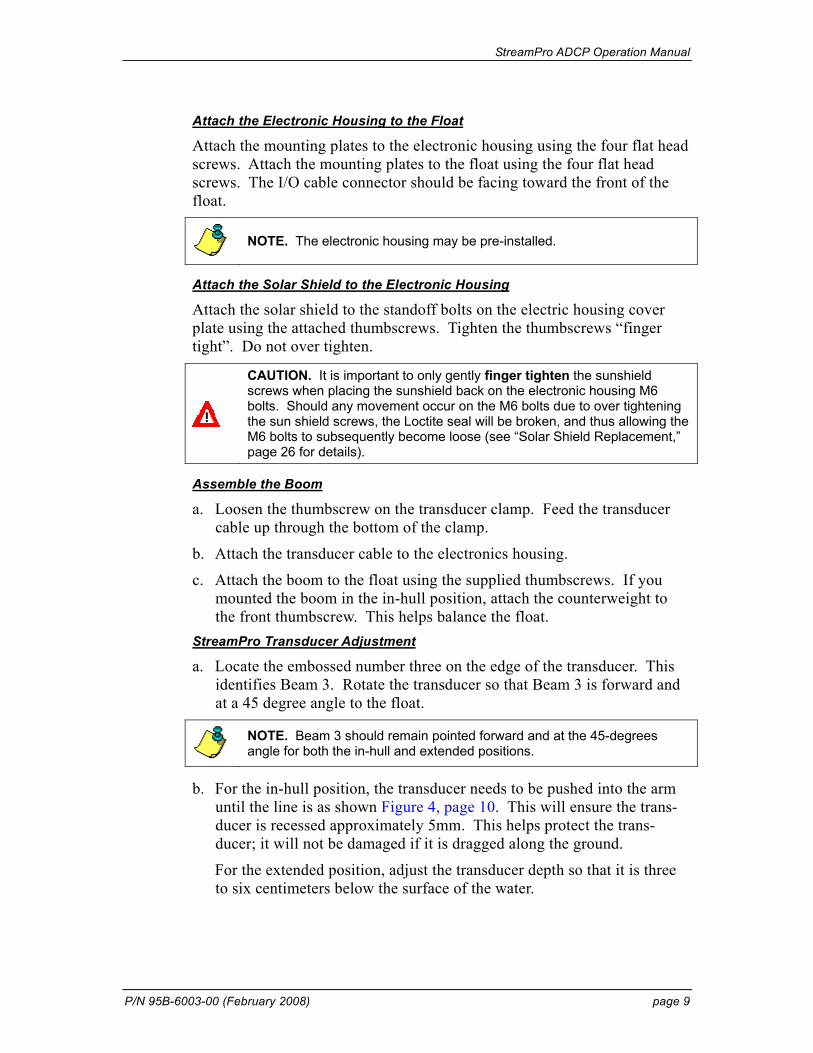
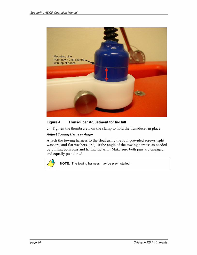
b. For the in-hull position, the transducer needs to be pushed into the arm until the line is as shown Figure 4, page 10. This will ensure the trans-ducer is recessed approximately 5mm. This helps protect the trans-ducer; it will not be damaged if it is dragged along the ground.
For the extended position, adjust the transducer depth so that it is three to six centimeters below the surface of the water.
StreamPro ADCP Operation Manual
page 10 Teledyne RD Instruments
Mounting LinePush down until alignedwith top of boom.
Figure 4. Transducer Adjustment for In-Hull
c. Tighten the thumbscrew on the clamp to hold the transducer in place. Adjust Towing Harness Angle
Attach the towing harness to the float using the four provided screws, split washers, and flat washers. Adjust the angle of the towing harness as needed by pulling both pins and lifting the arm. Make sure both pins are engaged and equally positioned.
NOTE. The towing harness may be pre-installed.
StreamPro ADCP Operation Manual
P/N 95B-6003-00 (February 2008) page 11
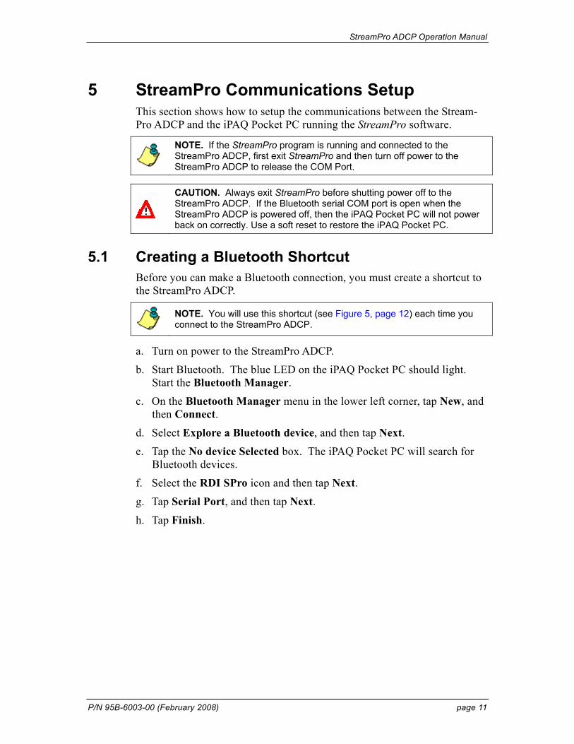
5 StreamPro Communications Setup This section shows how to setup the communications between the Stream-Pro ADCP and the iPAQ Pocket PC running the StreamPro software.
NOTE. If the StreamPro program is running and connected to the StreamPro ADCP, first exit StreamPro and then turn off power to the StreamPro ADCP to release the COM Port.
CAUTION. Always exit StreamPro before shutting power off to the StreamPro ADCP. If the Bluetooth serial COM port is open when the StreamPro ADCP is powered off, then the iPAQ Pocket PC will not power back on correctly. Use a soft reset to restore the iPAQ Pocket PC.
5.1 Creating a Bluetooth Shortcut Before you can make a Bluetooth connection, you must create a shortcut to the StreamPro ADCP.
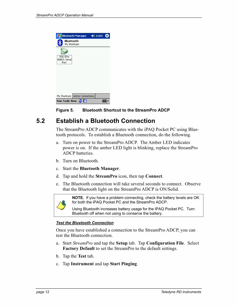
NOTE. You will use this shortcut (see Figure 5, page 12) each time you connect to the StreamPro ADCP.
a. Turn on power to the StreamPro ADCP.
b. Start Bluetooth. The blue LED on the iPAQ Pocket PC should light. Start the Bluetooth Manager.
c. On the Bluetooth Manager menu in the lower left corner, tap New, and then Connect.
d. Select Explore a Bluetooth device, and then tap Next.
e. Tap the No device Selected box. The iPAQ Pocket PC will search for Bluetooth devices.
f. Select the RDI SPro icon and then tap Next.
g. Tap Serial Port, and then tap Next.
h. Tap Finish.
StreamPro ADCP Operation Manual
page 12 Teledyne RD Instruments
Figure 5. Bluetooth Shortcut to the StreamPro ADCP
5.2 Establish a Bluetooth Connection The StreamPro ADCP communicates with the iPAQ Pocket PC using Blue-tooth protocols. To establish a Bluetooth connection, do the following.
a. Turn on power to the StreamPro ADCP. The Amber LED indicates power is on. If the amber LED light is blinking, replace the StreamPro ADCP batteries.
b. Turn on Bluetooth.
c. Start the Bluetooth Manager.
d. Tap and hold the StreamPro icon, then tap Connect.
e. The Bluetooth connection will take several seconds to connect. Observe that the Bluetooth light on the StreamPro ADCP is ON/Solid.
NOTE. If you have a problem connecting, check the battery levels are OK for both the iPAQ Pocket PC and the StreamPro ADCP.
Using Bluetooth increases battery usage for the iPAQ Pocket PC. Turn Bluetooth off when not using to conserve the battery.
Test the Bluetooth Connection
Once you have established a connection to the StreamPro ADCP, you can test the Bluetooth connection.
a. Start StreamPro and tap the Setup tab. Tap Configuration File. Select Factory Default to set the StreamPro to the default settings.
b. Tap the Test tab.
c. Tap Instrument and tap Start Pinging.
StreamPro ADCP Operation Manual
P/N 95B-6003-00 (February 2008) page 13
NOTE. Pinging in air will display the Number Good Bins as 0 and Velocity as BAD. This is normal and will not harm the StreamPro ADCP.
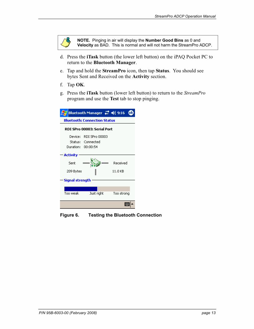
d. Press the iTask button (the lower left button) on the iPAQ Pocket PC to return to the Bluetooth Manager.
e. Tap and hold the StreamPro icon, then tap Status. You should see bytes Sent and Received on the Activity section.
f. Tap OK.
g. Press the iTask button (lower left button) to return to the StreamPro program and use the Test tab to stop pinging.
Figure 6. Testing the Bluetooth Connection
StreamPro ADCP Operation Manual
page 14 Teledyne RD Instruments
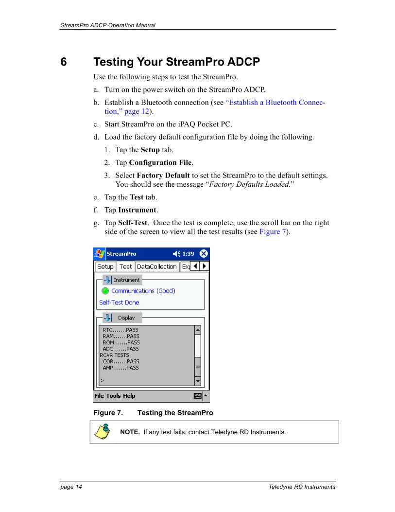
6 Testing Your StreamPro ADCP Use the following steps to test the StreamPro.
a. Turn on the power switch on the StreamPro ADCP.
b. Establish a Bluetooth connection (see “Establish a Bluetooth Connec-tion,” page 12).
c. Start StreamPro on the iPAQ Pocket PC.
d. Load the factory default configuration file by doing the following.
1. Tap the Setup tab.
2. Tap Configuration File.
3. Select Factory Default to set the StreamPro to the default settings. You should see the message “Factory Defaults Loaded.”
e. Tap the Test tab.
f. Tap Instrument.
g. Tap Self-Test. Once the test is complete, use the scroll bar on the right side of the screen to view all the test results (see Figure 7).
Figure 7. Testing the StreamPro
NOTE. If any test fails, contact Teledyne RD Instruments.
StreamPro ADCP Operation Manual
P/N 95B-6003-00 (February 2008) page 15
7 Troubleshooting If you have problems establishing a Bluetooth communication link, check the following items and use Table 3, page 16.
a. Does the StreamPro have power ON? Is the amber LED on? A blinking amber LED indicates the battery level is low. Replace the AA batteries with eight fresh batteries and try again to establish a Bluetooth commu-nication link.
b. Is the blue LED on the iPAQ Pocket PC lit? If not, charge the iPAQ Pocket PC battery.
NOTE. If the iPAQ Pocket PC battery voltage is too low, Bluetooth will not turn on. Charge the battery before continuing.
c. If the Bluetooth serial COM port is open when the StreamPro ADCP is powered off, then the iPAQ Pocket PC will not power back on correctly. Use a soft reset to restore the iPAQ Pocket PC.
NOTE. Always exit StreamPro and turn Bluetooth off before shutting power off to the StreamPro ADCP.
d. Is the iPAQ Pocket PC within 10 meters of the StreamPro?
e. Test the Bluetooth connection (see “Establish a Bluetooth Connection,” page 12).
CAUTION. Bluetooth communications will not work if the internal temperature of the StreamPro ADCP is above 50 degrees C. If you are having communication problems and are operating in a hot, sunny climate, allow the StreamPro ADCP to cool before continuing.
NOTE. Storing the StreamPro ADCP in the trunk of a car on a sunny day can cause the internal temperature of the StreamPro ADCP to exceed 50 degrees C.
StreamPro ADCP Operation Manual
page 16 Teledyne RD Instruments
Table 3: Troubleshooting the StreamPro ADCP Problem / Indication Possible Solution
Amber LED on the StreamPro ADCP does not light
Replace the StreamPro ADCP AA batteries.
Amber LED on the StreamPro ADCP is blinking
The battery level is getting low. Replace the StreamPro ADCP AA batteries.
Blue LED on the StreamPro ADCP does not light
COM port is locked. Do a shutdown and cold start (see Quick Start Guide).
Replace StreamPro ADCP AA batteries
Charge the iPAQ Pocket PC battery
StreamPro ADCP internal temperature may be above 50° C. Move the StreamPro ADCP to a cooler location and attempt to communi-cate again.
Blue LED on iPAQ Pocket PC does not light
Charge iPAQ Pocket PC battery
No Bluetooth/Wireless icon visible on Today screen
Do a soft reset on the iPAQ Pocket PC
iPAQ Pocket iPAQ Pocket PC will not turn on
Charge iPAQ Pocket PC battery for at least one hour. You may need to do a soft reset to restore normal operation.
iPAQ Pocket PC charge light will not light when placed in the charger
The battery may have totally discharged. Place the iPAQ Pocket PC in the charger for at least one hour. You may need to do a soft reset after the first hour of charging to fully charge the battery.
Bluetooth connection is intermittent Out of range – The iPAQ Pocket PC must be within 10 meters of the StreamPro ADCP.
StreamPro ADCP internal temperature may be above 50° C. Move the StreamPro ADCP to a cooler location and attempt to communi-cate again.
Replace the StreamPro ADCP AA batteries
Charge the iPAQ Pocket PC battery
CAUTION. The serial port is always open while StreamPro is running. Always exit StreamPro and turn Bluetooth off before shutting power off to the StreamPro ADCP or removing the SD storage card.
Performing a shutdown and cold start will release the COM Port.
In rare cases it may be necessary to perform a hard reset. See the StreamPro Software User’s Guide for details on how to do a hard reset.
StreamPro ADCP Operation Manual
P/N 95B-6003-00 (February 2008) page 17
8 StreamPro Maintenance This section explains how to prepare the StreamPro for deployment, how to do certain maintenance, and how to prepare the StreamPro for storage or shipment.
8.1 Spare Parts The following parts are included in the spare parts kit.
Table 4: Spare Parts Description Part number
O-ring, housing cover 2-162
O-ring, battery cover 2-036
Desiccant, sealed bag DES3
Lubricant, silicone, 5.3 oz, Dow-Corning DC-111
Holder, battery BH48AASF
Screw, thumb, 6-32x5/8, SS 91035A400
Screw, thumb, M40x0.7x14.5MM, SS 95536A331
Washer, wavy, .24ID x .31 OD x0.3THK, 302 SS 9714K23
Washer, 6mm Split Lock, SS316 M6WASHSPL
Washer, Flat, 12.5MMOD, SST 316 M6WASHSTD
Screw, SHCS, 316 M6X1.0X20SHCS
Screw, SKT HD, SST 316 M6x1.0x30SH
StreamPro ADCP Operation Manual
page 18 Teledyne RD Instruments
LOCK WASHER
M6 BOLT
FLAT WASHER
THUMB SCREWS
HOUSING COVER
COVER PLATEO-RING
POWER SWITCHand LEDs
PROTECTIVECAP
BATTERYPACK
BATTERYCOVERO-RING
BATTERYCOVER
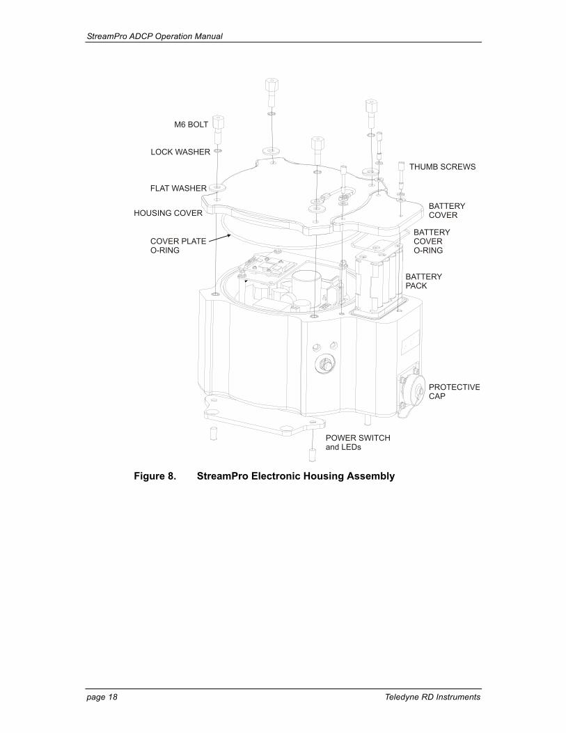
Figure 8. StreamPro Electronic Housing Assembly
StreamPro ADCP Operation Manual
P/N 95B-6003-00 (February 2008) page 19
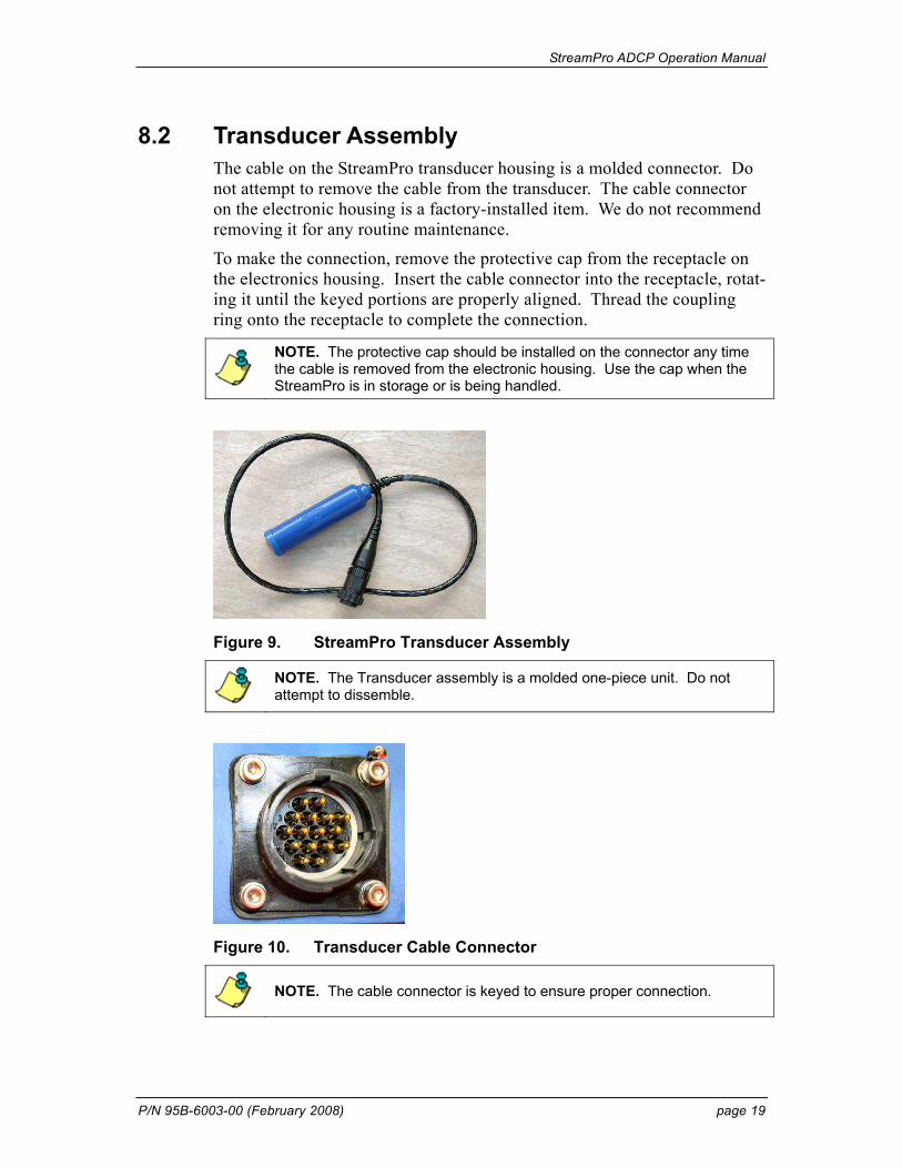
8.2 Transducer Assembly The cable on the StreamPro transducer housing is a molded connector. Do not attempt to remove the cable from the transducer. The cable connector on the electronic housing is a factory-installed item. We do not recommend removing it for any routine maintenance.
To make the connection, remove the protective cap from the receptacle on the electronics housing. Insert the cable connector into the receptacle, rotat-ing it until the keyed portions are properly aligned. Thread the coupling ring onto the receptacle to complete the connection.
NOTE. The protective cap should be installed on the connector any time the cable is removed from the electronic housing. Use the cap when the StreamPro is in storage or is being handled.
Figure 9. StreamPro Transducer Assembly
NOTE. The Transducer assembly is a molded one-piece unit. Do not attempt to dissemble.
Figure 10. Transducer Cable Connector
NOTE. The cable connector is keyed to ensure proper connection.
StreamPro ADCP Operation Manual
page 20 Teledyne RD Instruments
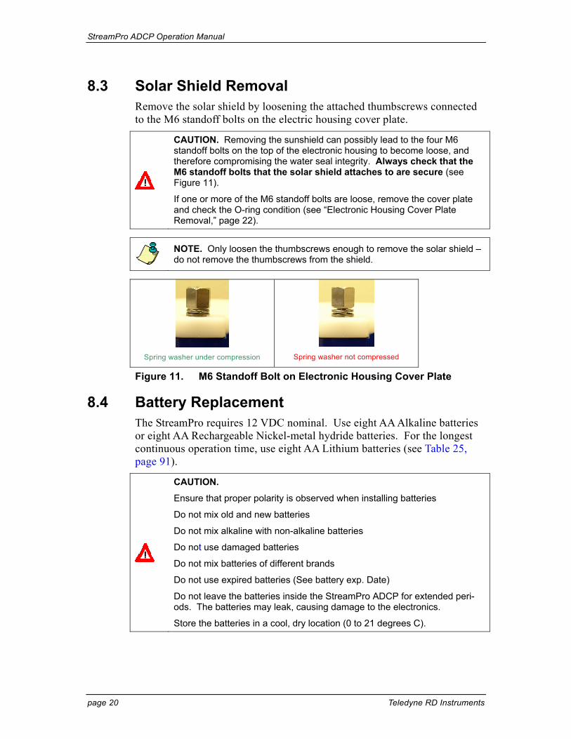
8.3 Solar Shield Removal Remove the solar shield by loosening the attached thumbscrews connected to the M6 standoff bolts on the electric housing cover plate.
CAUTION. Removing the sunshield can possibly lead to the four M6 standoff bolts on the top of the electronic housing to become loose, and therefore compromising the water seal integrity. Always check that the M6 standoff bolts that the solar shield attaches to are secure (see Figure 11).
If one or more of the M6 standoff bolts are loose, remove the cover plate and check the O-ring condition (see “Electronic Housing Cover Plate Removal,” page 22).
NOTE. Only loosen the thumbscrews enough to remove the solar shield – do not remove the thumbscrews from the shield.
Spring washer under compression
Spring washer not compressed
Figure 11. M6 Standoff Bolt on Electronic Housing Cover Plate
8.4 Battery Replacement The StreamPro requires 12 VDC nominal. Use eight AA Alkaline batteries or eight AA Rechargeable Nickel-metal hydride batteries. For the longest continuous operation time, use eight AA Lithium batteries (see Table 25, page 91).
CAUTION.
Ensure that proper polarity is observed when installing batteries
Do not mix old and new batteries
Do not mix alkaline with non-alkaline batteries
Do not use damaged batteries
Do not mix batteries of different brands
Do not use expired batteries (See battery exp. Date)
Do not leave the batteries inside the StreamPro ADCP for extended peri-ods. The batteries may leak, causing damage to the electronics.
Store the batteries in a cool, dry location (0 to 21 degrees C).

StreamPro ADCP Operation Manual
P/N 95B-6003-00 (February 2008) page 21
NOTE. When using eight AA cells, check that the battery voltage is above 11.5 Volts DC. StreamPro ADCPs will work at 11.5 volts; however, batteries with voltages below 11.5 volts are at or near their end of life and are approaching uselessness.
A blinking amber LED indicates the battery level is low.
Replace the batteries by doing the following.
a. Turn the power switch OFF.
b. Remove the solar shield by loosing the four thumbscrews.
c. Open the battery compartment door by loosening the three thumbscrews.
NOTE. Only loosen the thumbscrews enough to remove the cover – do not remove the thumbscrews from the battery cover.
d. Remove the battery holder.
e. Remove all of the old batteries.
f. Replace with eight new Alkaline AA batteries. Match the battery polar-ity as shown on the battery holder.
g. Observe that the inside of the battery housing area is dry and clean. Thoroughly clean both the cover plate and the blue surface area around the O-ring.
h. Place the battery holder in the housing making sure the battery contacts on the holder match the two springs inside the housing (see Figure 12, page 22).
i. The battery compartment O-ring is normally held in place because the groove it sits in is dovetailed. Should the O-ring ever fall out or it ap-pears dry or hard, replace it and apply the smallest amount possible of the silicone lubricant included in the tool kit. Beware too much lubri-cant attracts dirt; therefore apply it exceedingly sparingly. Use a lint free cloth to remove any excess lubricant (see “Battery Compartment O-Ring Inspection & Replacement,” page 24).
j. Close the battery compartment door and tighten the thumbscrews. As you tighten all three thumbscrews, tilt the housing to see that the O-ring has not moved out of the O-ring slot (see Figure 13, page 22). Tighten all three thumbscrews in rotation a couple turns at a time so that the cover comes down evenly and squarely on the housing. Only tighten the battery cover thumbscrews finger tight.
CAUTION. Although each thumbscrew has a screwdriver slot, do NOT use any tools to tighten the screws. Over-tightening can cause the threads to strip.
StreamPro ADCP Operation Manual
page 22 Teledyne RD Instruments
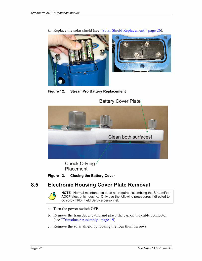
k. Replace the solar shield (see “Solar Shield Replacement,” page 26).
Figure 12. StreamPro Battery Replacement
Battery Cover Plate
Check O-RingPlacement
Clean both surfaces!
Figure 13. Closing the Battery Cover
8.5 Electronic Housing Cover Plate Removal
NOTE. Normal maintenance does not require dissembling the StreamPro ADCP electronic housing. Only use the following procedures if directed to do so by TRDI Field Service personnel.
a. Turn the power switch OFF.
b. Remove the transducer cable and place the cap on the cable connector (see “Transducer Assembly,” page 19).
c. Remove the solar shield by loosing the four thumbscrews.
StreamPro ADCP Operation Manual
P/N 95B-6003-00 (February 2008) page 23
d. Open the battery compartment door and remove the battery pack (see “Battery Replacement,” page 20).
e. Loosen (do not remove) the four standoff bolts (M6) to vent the system.
f. Once all four bolts have been loosened, remove the four bolts that attach the housing cover to the housing assembly. Check inside the housing for any discoloration or water damage. If in doubt, contact Teledyne RD Instruments.
g. Clean the O-ring mating surfaces with a soft, lint-free cloth. Inspect the surfaces for damage (see “Cover Plate O-Ring Inspection and Replace-ment,” page 23).
h. When you are ready to re-assemble the StreamPro, see “StreamPro Re-assembly,” page 23.
8.6 StreamPro Re-assembly To replace the housing cover plate, proceed as follows.
8.6.1 Cover Plate O-Ring Inspection and Replacement This section explains how to inspect/replace the StreamPro O-ring. A suc-cessful deployment depends on the condition of O-ring and the retaining groove. Read all instructions before doing the required actions.
We strongly recommend cleaning the O-ring whenever you disassemble the StreamPro. Inspecting and cleaning the O-ring should be the last mainte-nance task done before sealing the StreamPro.
a. Inspect the O-ring. When viewed with an unaided eye, the O-ring must be free of cuts, indentations, abrasions, foreign matter, and flow marks. The O-ring must be smooth and uniform in appearance. Defects must be less then 0.1 mm (0.004 in.).
CAUTION. If the O-ring appears compressed from prior use, replace it. Weak or damaged O-rings will cause the StreamPro to flood.
b. Clean and inspect the O-ring groove. Be sure the groove is free of for-eign matter, scratches, indentations, corrosion, and pitting. Run your fingernail across damaged areas. If you cannot feel the defect, the dam-age may be minor; otherwise, the damage may need repair.
CAUTION. Check the O-ring groove thoroughly. Any foreign matter in the O-ring groove will cause the StreamPro to flood.
c. If a scratch is on the plastic housing flange O-ring groove, it may be gently sanded using 600-grit (wet) sandpaper. Use care not to cause fur-ther damage.
StreamPro ADCP Operation Manual
page 24 Teledyne RD Instruments
d. Lubricate the O-ring with a thin coat of silicone lubricant. Apply the lubricant using latex gloves. Do not let loose fibers or lint stick to the O-ring. Fibers can provide a leakage path.
NOTE. TRDI uses Dow Corning’s silicone lube model number 111 but any type of silicone O-ring lube can be used.
CAUTION. Apply a very thin coat of silicone lube on the O-ring. Using too much silicone lube on the O-ring can be more harmful than using no O-ring lube at all.
8.6.2 Battery Compartment O-Ring Inspection & Replacement The battery compartment O-ring is normally held in place because the groove it sits in is dovetailed. Should the O-ring ever fall out or it appears dry or hard, replace it. Replace the Battery Compartment O-Ring by doing the following.
a. Turn the power switch OFF.
b. Remove the solar shield by loosing the four thumbscrews.
c. Open the battery compartment door by loosening the thumbscrew.
d. Inspect the O-ring. When viewed with an unaided eye, the O-ring must be free of cuts, indentations, abrasions, foreign matter, and flow marks. The O-ring must be smooth and uniform in appearance. Defects must be less then 0.1 mm (0.004 in.).
CAUTION. If the O-ring appears compressed from prior use, replace it. Weak or damaged O-rings will cause the StreamPro to flood.
e. Clean and inspect the O-ring groove and the surface around the O-ring. Be sure the groove is free of foreign matter, scratches, indentations, cor-rosion, and pitting. Run your fingernail across damaged areas. If you cannot feel the defect, the damage may be minor; otherwise, the damage may need repair. Clean the battery cover plate with a lint free cloth.
CAUTION. Check the O-ring groove thoroughly. Any foreign matter in the O-ring groove will cause the StreamPro to flood.
f. Lubricate the O-ring with a thin coat of silicone lubricant. Apply the lubricant using latex gloves. Do not let loose fibers or lint stick to the O-ring. Fibers can provide a leakage path.
NOTE. TRDI uses Dow Corning’s silicone lube model number 111 but any type of silicone O-ring lube can be used.
StreamPro ADCP Operation Manual
P/N 95B-6003-00 (February 2008) page 25
CAUTION. Be aware that too much lubricant attracts dirt; therefore apply it exceedingly sparingly. Use a lint free cloth to remove any excess lubricant.
g. Check that the battery compartment O-ring is in the O-ring groove (see Figure 13, page 22).
h. Close the battery compartment door and tighten the thumbscrew. Only tighten the battery cover thumbscrews finger tight.
CAUTION. Although each thumbscrew has a screwdriver slot, do NOT use any tools to tighten the screws. Over-tightening can cause the threads to strip.
8.6.3 Electronic Housing Cover Plate Replacement When replacing the cover plate, observe that the inside of the housing area is dry and clean. There should be no signs of water ingress, discoloration, or dampness. If in doubt, contact Teledyne RD Instruments.
a. Make sure all printed circuit boards, spacers, cables, and screws have been installed.
b. Inspect, clean, and lubricate the O-ring on the housing (see “Cover Plate O-Ring Inspection and Replacement,” page 23).
CAUTION. Follow all the steps for O-Ring Inspection and Replacement (see “Cover Plate O-Ring Inspection and Replacement,” page 23). The watertight integrity of the StreamPro depends on this seal.
c. Install two fresh bags of desiccant just before closing the StreamPro (see “Desiccant Bags,” page 26).
d. Gently place the cover onto the housing assembly, aligning the mating holes. When mating the cover with the housing flange try to apply equal pressure to all parts of the O-ring. Make sure the O-ring remains in the retaining groove.
CAUTION. Check that no wires or any other object is pinched between the cover and the housing. If the O-ring is not in the groove or if a wire or other object is pinched, the StreamPro will flood.
e. Examine the housing assembly standoff bolts, split washer, and flat washers (M6) for corrosion: replace if necessary. All hardware items are needed to seal the StreamPro properly.
f. Place one drop of Loctite 425 on the M6 standoff bolts during reassembly.
g. Install all four sets of hardware until “finger tight.”
StreamPro ADCP Operation Manual
page 26 Teledyne RD Instruments
h. Tighten the standoff bolts in small increments in a “cross” pattern until there is no gap between the cover plate and housing, and then tighten each standoff bolt ¼ turn more to compress the face seal O-ring evenly. Tighten the M6 standoff bolts to 10 inch/pounds (1.13 nm).
CAUTION. Apply equal pressure to the O-ring as you tighten the bolts. If one bolt is tightened more then the others, the O-ring can become pinched or torn. A damaged O-ring will cause the StreamPro to flood.
CAUTION. Do not over tighten the bolts that hold the cover plate and housing together. If you tighten too much, you can crack or deform the plastic cover. On the other hand, leaving the bolts too loose can cause the system to flood.
Tighten the M6 standoff bolts to 10 inch/pounds (1.13 nm).
i. Slide the battery pack into the compartment and check that the battery compartment O-ring is in the retaining groove. Close and tighten the battery compartment door.
8.7 Solar Shield Replacement Attach the solar shield to the standoff bolts on the electric housing cover plate using the attached thumbscrews. Tighten the thumbscrews “finger tight”. Do not over tighten.
CAUTION. It is important to only gently finger tighten the sunshield screws when placing the sunshield back on the electronic housing M6 standoff bolts. Should any movement occur on the M6 standoff bolts due to over tightening the sun shield screws, the Loctite seal will be broken, and thus allowing the M6 standoff bolts to subsequently become loose (see Figure 11, page 20).
8.8 Desiccant Bags Desiccant bags are used to dehumidify the housing interior. Desiccant is essential in deployments with plastic housings. The factory-supplied desic-cant lasts a year. Remember that desiccant rapidly absorbs moisture from normal room air if the housing is opened.
The average dry weight of a new desiccant bag is 7.2 grams ((5%). The weight increases to 8.4 to 9 grams for a “used” desiccant bag. Used desic-cant bags may be dried at 250° for 14 hours. As a minimum, replace the desiccant bags once per year or whenever you are preparing to store the StreamPro for an extended time.
CAUTION. Do not open the desiccant bag. Contact with the silica gel can cause nose, throat, and skin irritation.
StreamPro ADCP Operation Manual
P/N 95B-6003-00 (February 2008) page 27
NOTE. Desiccant bags are shipped in an airtight aluminum bag to ensure maximum effectiveness. There is a moisture indicator inside the bag. If the moisture indicator is pink, do not use the desiccant bag until it has been dried. TRDI recommends replacing the desiccant bag once per year.
a. Remove the housing cover plate (see “Electronic Housing Cover Plate Removal,” page 22).
b. Remove the new desiccant bags from the airtight aluminum bag.
c. Remove the old desiccant bags and install two new ones. Place the des-iccant bags between the top circuit board and the housing.
d. Install the housing cover plate (see “Electronic Housing Cover Plate Re-placement,” page 25).
8.9 Storage and Shipping Maintenance This section lists the maintenance items to do before storing the StreamPro. These maintenance items include:
• Removing biofouling (see “Removal of Biofouling,” page 27).
• Inspecting the transducer head (see “Transducer Head Inspec-tion,” page 28).
• Preparing the StreamPro for final storage (see “Final Storage,” page 28)
• Shipping Preparation (see “Shipping Preparation,” page 30)
8.9.1 Removal of Biofouling Before storing or shipping the StreamPro, remove all foreign matter and biofouling. Remove soft-bodied marine growth or foreign matter with soapy water. Waterless hand cleaners remove most petroleum-based foul-ing. Rinse with fresh water to remove soap residue. Dry the transducer faces with low-pressure compressed air or soft lint-free towels. Dry the float and electronics housing with towels.
CAUTION. The soft, thin urethane coating on the transducer faces is easily damaged. Do not use power scrubbers, abrasive cleansers, scouring pads, high-pressure marine cleaning systems, or brushes stiffer than hand cleaning brushes on the transducer faces.
CAUTION. Always dry the StreamPro before placing it in the storage case to avoid fungus or mold growth. Do not store the StreamPro ADCP in wet or damp locations.
StreamPro ADCP Operation Manual
page 28 Teledyne RD Instruments
8.9.2 Transducer Head Inspection The urethane coating on the transducer faces is important to StreamPro wa-tertight integrity. Mishandling, chemicals, abrasive cleaners, and excessive depth pressures can damage the transducer ceramics or urethane coating. Inspect the transducer faces for dents, chipping, peeling, urethane shrink-age, hairline cracks, and damage that may affect watertight integrity or transducer operation. Repair of the transducer faces should only be done by TRDI.
CAUTION. Never set the transducer on a rough surface; always use foam padding to protect the transducer.
NOTE. The cap should be installed any time the transducer cable is removed. Use the cap when the StreamPro is in storage or is being handled.
8.9.3 Final Storage Store the StreamPro in the original shipping crate whenever possible.
a. Remove the batteries from the battery holder.
b. Remove the transducer from the boom arm and disconnect the trans-ducer cable. Place the protective cap on the electronic housing trans-ducer cable connector.
c. Dissemble the boom arm from the float.
d. Place the transducer and boom arm in the foam cutouts in the bottom of the shipping case.
e. The electronic housing/float assembly fits in the case with the electronic housing held in place by the cutout in the foam. Use the other cutout to store the iPAQ Pocket PC, manuals, and spare parts.
StreamPro ADCP Operation Manual
P/N 95B-6003-00 (February 2008) page 29
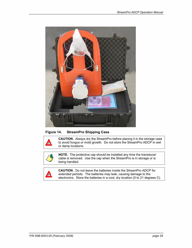
Figure 14. StreamPro Shipping Case
CAUTION. Always dry the StreamPro before placing it in the storage case to avoid fungus or mold growth. Do not store the StreamPro ADCP in wet or damp locations.
NOTE. The protective cap should be installed any time the transducer cable is removed. Use the cap when the StreamPro is in storage or is being handled.
CAUTION. Do not leave the batteries inside the StreamPro ADCP for extended periods. The batteries may leak, causing damage to the electronics. Store the batteries in a cool, dry location (0 to 21 degrees C).
StreamPro ADCP Operation Manual
page 30 Teledyne RD Instruments
8.9.4 Shipping Preparation This section explains how to ship the StreamPro.
CAUTION. If you are shipping a StreamPro to TRDI for repair or upgrade, remove all customer-applied coatings or provide certification that the coating is nontoxic. This certification must include the name of a contact person who is knowledgeable about the coating, the name, and manufacturer of the coating, and the appropriate telephone numbers. If you return the equipment without meeting these conditions, we have instructed our employees not to handle the equipment and to leave it in the original shipping container pending certification. If you cannot provide certification, we will return the equipment to you or to a customer-specified cleaning facility. All costs associated with customer-applied coatings will be at the customer's expense.
When shipping the StreamPro through a Customs facility, be sure to place the unit/s so identifying labels are not covered and can be seen easily by the Customs Inspector. Failure to do so could delay transit time.
NOTE. TRDI strongly recommends using the original shipping crate whenever transporting the StreamPro.
If you need to ship or store the StreamPro, use the original shipping crate whenever possible. If the original packaging material is unavailable or un-serviceable, additional material is available through TRDI.
For repackaging with commercially available materials, use the following procedure:
a. Remove the transducer assembly from the boom arm.
b. Remove the electronic housing from the float.
c. Use a strong shipping container made out of wood or plastic.
d. Install a layer of shock-absorbing static-shielding material, 70-mm to 100-mm thick, around all sides of the instrument to firmly cushion and prevent movement inside the container.
e. Seal the shipping container securely.
f. Mark the container FRAGILE to ensure careful handing.
g. In any correspondence, refer to the StreamPro by model and serial number.

StreamPro ADCP Operation Manual
P/N 95B-6003-00 (February 2008) page 31
8.10 Returning StreamPro ADCPs to TRDI for Service When shipping the StreamPro to TRDI from either inside or outside the United States, the following instructions will help ensure the StreamPro ar-rives with the minimum possible delay. Any deviation from these instruc-tions increases the potential for delay.
8.10.1 Domestic Shipments Step 1 - Get a Return Material Authorization
Send an e-mail to TRDI’s Sales Administration ([email protected]) or call Customer Service and request a Return Material Authorization (RMA) number. When requesting a RMA number, please give us the following in-formation.
• What is being shipped (include the serial number)
• When you plan to send the shipment
• What issue(s) need to be corrected
• Name of the Field Service Engineer that knows about the issue
• When you need the instrument returned
TRDI’s Customer Service will then respond with the RMA number for the shipment. Please include this number on all packages and correspondence. Step 2 – Provide a MSDS as necessary
Please provide a Material Safety Data Sheet (MSDS) if the sys-tem/transducer is painted with antifouling paint. Step 3 - Ship via air freight, prepaid
Urgent Shipments should be shipped direct to TRDI via overnight or prior-ity air services. Do not send urgent airfreight as part of a consolidated shipment. If you ship consolidated, it will cost less, but may lose up to three days in transit time.
Non-urgent shipments may be shipped as part of a consolidated cargo ship-ment to save money. In addition, some truck lines may offer equivalent de-livery service at a lower cost, depending on the distance to San Diego.
Mark the Package(s) To: Teledyne RD Instruments, Inc. (RMA Number)
14020 Stowe Drive Poway, California 92064
Airport of Destination = San Diego Notify Paxton, Shreve, and Hayes, San Diego Airport Phone: +1 (619) 232-8941 Fax: +1 (619) 232-8976

StreamPro ADCP Operation Manual
page 32 Teledyne RD Instruments
Step 4 - Urgent shipments
Send the following information by fax or telephone to TRDI. Attention: Customer Service Administration Fax: +1 (858) 842-2822 Phone: +1 (858) 842-2600
• Detailed descriptions of what you are shipping (number of pack-ages, sizes, weights, and contents).
• The name of the freight carrier
• Master Air bill number
• Carrier route and flight numbers for all flights the package will take
8.10.2 International Shipments Step 1 - Get a Return Material Authorization
Send an e-mail to TRDI’s Sales Administration ([email protected]) or call Customer Service and request a Return Material Authorization (RMA) number. When requesting a RMA number, please give us the following in-formation.
• What is being shipped (include the serial number)
• When you plan to send the shipment
• What issue(s) need to be corrected
• Name of the Field Service Engineer that knows about the issue
• When you need the instrument returned
TRDI’s Customer Service will then respond with the RMA number for the shipment. Please include this number on all packages and correspondence. Step 2 – Provide a MSDS as necessary
Please provide a Material Safety Data Sheet (MSDS) if the sys-tem/transducer is painted with antifouling paint. Step 3 - Ship Via Air Freight, Prepaid
Urgent Shipments should be shipped direct to TRDI via overnight or prior-ity air services. Do not send urgent airfreight as part of a consolidated shipment. If you ship consolidated, it will cost less, but may lose up to three days in transit time.
Non-urgent shipments may be shipped as part of a consolidated cargo ship-ment to save money.

StreamPro ADCP Operation Manual
P/N 95B-6003-00 (February 2008) page 33
Mark the package(s) as follows: To: Teledyne RD Instruments, Inc. (RMA Number) 2A Les Nertieres
5 Avenue Hector Pintus 06610 La Gaude, France
Step 4 - Include Proper Customs Documentation
The Customs statement must be completed. It should be accurate and truth-fully contain the following information.
• Contents of the shipment
• Value
• Purpose of shipment (example: “American made goods returned for repair”)
• Any discrepancy or inaccuracy in the Customs statement could cause the shipment to be delayed in Customs.
Step 4 - Send the Following Information by Fax or Telephone to TRDI
Attention: Sales Administration Phone: +33(0) 492-110-930 Fax: +33(0) 492-110-931
• Detailed descriptions of what you are shipping (number of pack-ages, sizes, weights, and contents).
• The name of the freight carrier
• Master Air bill number
• Carrier route and flight numbers for all flights the package will take
StreamPro ADCP Operation Manual
page 34 Teledyne RD Instruments
9 StreamPro Commands This section defines the commands used by the StreamPro ADCPs. These commands let you set up and control the StreamPro. The commands di-rectly affect the range of the StreamPro and the standard deviation (accu-racy) of the data. Most StreamPro settings use factory-set values. If you change these values without thought, you could ruin your deployment. Be sure you know what effect each command has before using it. Call TRDI if you do not understand the function of any command.
9.1 Data Communication and Command Format You can enter commands with an IBM-compatible computer with a Blue-tooth interface running TRDI’s BBTalk. The StreamPro communicates with the computer through the Bluetooth interface.
Immediately after you apply power to the StreamPro, it enters the standby mode. Send a = = = signal using BBTalk. When the StreamPro receives a = = = signal, it responds with a wake-up message similar to the one shown below. The StreamPro is now ready to accept commands at the “>” prompt. StreamPro ADCP Teledyne RD Instruments (c) 2003 All rights reserved. Firmware Version: xx.xx >
9.1.1 Command Input Processing Input commands set StreamPro operating parameters, start data collection, run built-in tests (BIT), and asks for output data. All commands are ASCII character(s) and must end with a carriage return (CR). For example, >WP0001<CR> [Your input]
If the entered command is valid, the StreamPro executes the command. If the command is one that does not provide output data, the StreamPro sends a carriage return line feed <CR> <LF> and displays a new “>” prompt. Continuing the example, >WP00001<CR> [Your original input] > [StreamPro response to a valid, no-output command]
If you enter a valid command that produces output data, the StreamPro exe-cutes the command, displays the output data, and then redisplays the “>” prompt. Some examples of commands that produce output data are ? (help menus), CS (start pinging), PS (system configuration data), and PA (run built-in tests).
If the command is not valid, the StreamPro responds with an error message similar to the following.
StreamPro ADCP Operation Manual
P/N 95B-6003-00 (February 2008) page 35
>WPA<CR> [Your input] >WPA ERR 002: NUMBER EXPECTED<CR><LF> [StreamPro response] >
After correctly entering all the commands for your application, you would send the CS-command to begin the data collection cycle.
9.1.2 Data Output Processing After the StreamPro completes a data collection cycle, it sends a block of data called a data ensemble. A data ensemble consists of the data collected and averaged during the ensemble interval. A data ensemble can contain header, leader, velocity, correlation magnitude, echo intensity, and percent good.
StreamPro output data can be in either hexadecimal-ASCII (Hex-ASCII) or binary format. The Hex-ASCII mode is useful when you use a terminal to communicate with, and view data from the StreamPro. The binary mode is useful for high-speed communication with a computer program. You would not use the binary mode to view data on a terminal because the terminal could interpret some binary data as control codes.
NOTE. All of Teledyne RD Instruments’ software supports binary PD0 Output Data Format only.
When data collection begins, the StreamPro uses the settings last entered (user settings) or the factory-default settings. The same settings are used for the entire deployment.
The StreamPro automatically stores the last set of commands used in RAM. The StreamPro will continue to be configured from RAM until it receives a CR-command or until the RAM loses its backup power. If the StreamPro receives a CR0 it will load into RAM the command set you last stored in non-volatile memory (semi-permanent user settings) through the CK-command. If the StreamPro receives a CR1, it will load into RAM the fac-tory default command set stored in ROM (permanent or factory settings).
StreamPro ADCP Operation Manual
page 36 Teledyne RD Instruments
9.2 Firmware Upgrades When updating the firmware, the new firmware must be downloaded to the StreamPro ADCP using the program WinCEFlash.exe. To download new firmware, do the following steps.
a. Copy the StreamPro firmware from the Teledyne RD Instruments web site customer service page using the following link: http://www.rdinstruments.com/x/cs/software.html#spro. Place the zip file on your computer’s hard drive and unzip the file. You should have the following files.
• WinCEFlash.exe • SPxx_xx.m0 (where xx_xx is the version number) • atlce400.dll
b. Place the iPAQ Pocket PC in the cradle.
c. When Microsoft ActiveSync starts, click the Explore icon.
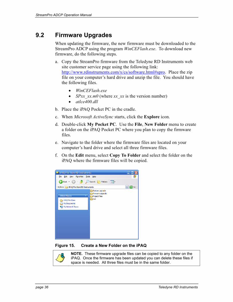
d. Double-click My Pocket PC. Use the File, New Folder menu to create a folder on the iPAQ Pocket PC where you plan to copy the firmware files.
e. Navigate to the folder where the firmware files are located on your computer’s hard drive and select all three firmware files.
f. On the Edit menu, select Copy To Folder and select the folder on the iPAQ where the firmware files will be copied.
Figure 15. Create a New Folder on the iPAQ
NOTE. These firmware upgrade files can be copied to any folder on the iPAQ. Once the firmware has been updated you can delete these files if space is needed. All three files must be in the same folder.
StreamPro ADCP Operation Manual
P/N 95B-6003-00 (February 2008) page 37
g. Before continuing, make sure the following conditions are met.
• Disconnect the transducer cable from the electronics housing. • StreamPro program is not running on the iPAQ Pocket PC. • StreamPro ADCP has fresh batteries. • StreamPro ADCP power turned ON. • iPAQ Pocket PC has fully charged battery. • Turn the iPAQ Pocket PC Bluetooth ON. • Make sure the iPAQ and StreamPro ADCP are in close proximity
to each other.
CAUTION. If the transducer cable is not removed from the electronic housing before the firmware upgrade starts, the beam matrix in the transducer will be overwritten. This will seriously degrade your measurements. If this happens, please contact TRDI for information on how to restore the beam matrix.
If the StreamPro ADCP batteries go dead or communications between the iPAQ and StreamPro ADCP is lost during the firmware upgrade, the firmware may be corrupted. If this happens, return the StreamPro ADCP to TRDI.
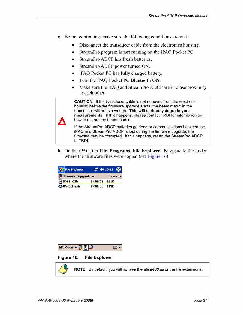
h. On the iPAQ, tap File, Programs, File Explorer. Navigate to the folder where the firmware files were copied (see Figure 16).
Figure 16. File Explorer
NOTE. By default, you will not see the atlce400.dll or the file extensions.
StreamPro ADCP Operation Manual
page 38 Teledyne RD Instruments
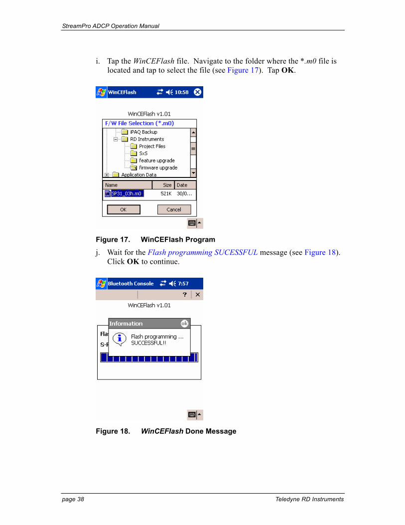
i. Tap the WinCEFlash file. Navigate to the folder where the *.m0 file is located and tap to select the file (see Figure 17). Tap OK.
Figure 17. WinCEFlash Program
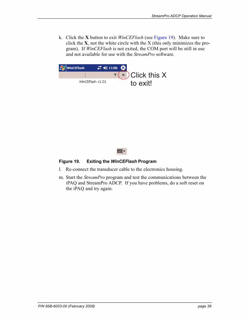
j. Wait for the Flash programming SUCESSFUL message (see Figure 18). Click OK to continue.
Figure 18. WinCEFlash Done Message
StreamPro ADCP Operation Manual
P/N 95B-6003-00 (February 2008) page 39
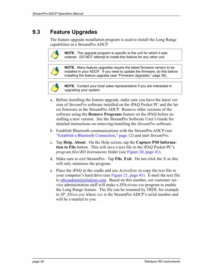
k. Click the X button to exit WinCEFlash (see Figure 19). Make sure to click the X, not the white circle with the X (this only minimizes the pro-gram). If WinCEFlash is not exited, the COM port will be still in use and not available for use with the StreamPro software.
Click this Xto exit!
Figure 19. Exiting the WinCEFlash Program
l. Re-connect the transducer cable to the electronics housing.
m. Start the StreamPro program and test the communications between the iPAQ and StreamPro ADCP. If you have problems, do a soft reset on the iPAQ and try again.
StreamPro ADCP Operation Manual
page 40 Teledyne RD Instruments
9.3 Feature Upgrades The feature upgrade installation program is used to install the Long Range capabilities in a StreamPro ADCP.
NOTE. The upgrade program is specific to the unit for which it was ordered. DO NOT attempt to install this feature for any other unit.
NOTE. Many feature upgrades require the latest firmware version to be installed in your ADCP. If you need to update the firmware, do this before installing the feature upgrade (see “Firmware Upgrades,” page 36).
NOTE. Contact your local sales representative if you are interested in upgrading your system.
a. Before installing the feature upgrade, make sure you have the latest ver-sion of StreamPro software installed on the iPAQ Pocket PC and the lat-est firmware in the StreamPro ADCP. Remove older versions of the software using the Remove Programs feature on the iPAQ before in-stalling a new version. See the StreamPro Software User’s Guide for detailed instructions on removing/installing the StreamPro software.
b. Establish Bluetooth communications with the StreamPro ADCP (see “Establish a Bluetooth Connection,” page 12) and start StreamPro.
c. Tap Help, About. On the Help screen, tap the Capture PS0 Informa-tion to File button. This will save a text file to the iPAQ Pocket PC’s program files\RD Instruments folder (see Figure 20, page 41).
d. Make sure to exit StreamPro. Tap File, Exit. Do not click the X as this will only minimize the program.
e. Place the iPAQ in the cradle and use ActiveSync to copy the text file to your computer’s hard drive (see Figure 21, page 41). E-mail the text file to [email protected]. Based on this number, our customer ser-vice administration staff will make a SPActivate.exe program to enable the Long Range feature. The file can be renamed by TRDI, for example to SP_SNxxx.exe where xxx is the StreamPro ADCP’s serial number and will be e-mailed to you.
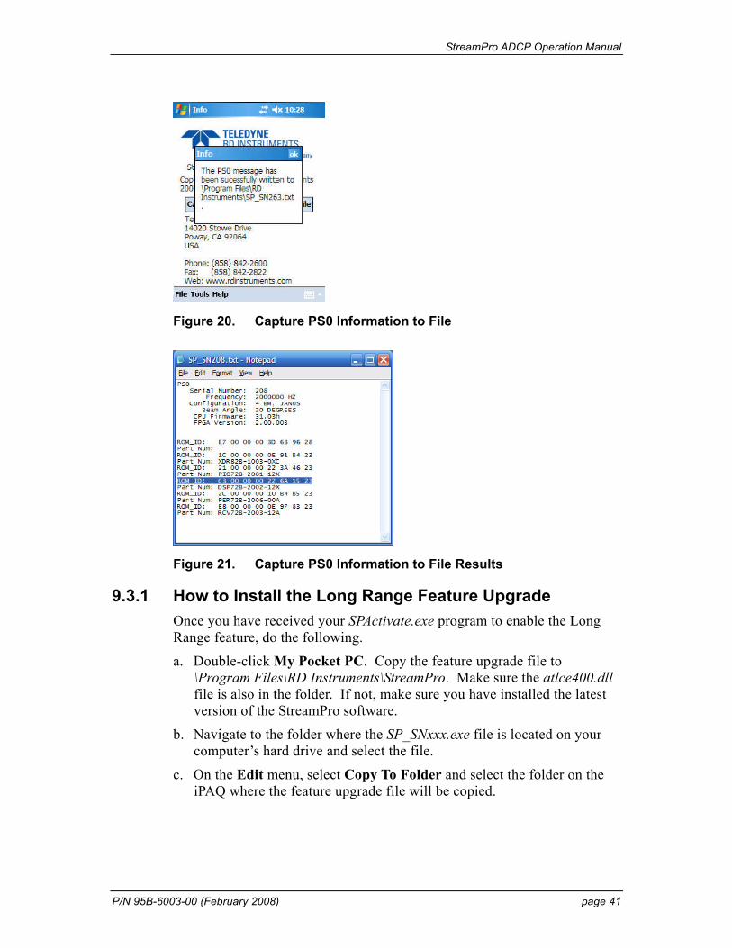
StreamPro ADCP Operation Manual
P/N 95B-6003-00 (February 2008) page 41
Figure 20. Capture PS0 Information to File
Figure 21. Capture PS0 Information to File Results
9.3.1 How to Install the Long Range Feature Upgrade Once you have received your SPActivate.exe program to enable the Long Range feature, do the following.
a. Double-click My Pocket PC. Copy the feature upgrade file to \Program Files\RD Instruments\StreamPro. Make sure the atlce400.dll file is also in the folder. If not, make sure you have installed the latest version of the StreamPro software.
b. Navigate to the folder where the SP_SNxxx.exe file is located on your computer’s hard drive and select the file.
c. On the Edit menu, select Copy To Folder and select the folder on the iPAQ where the feature upgrade file will be copied.
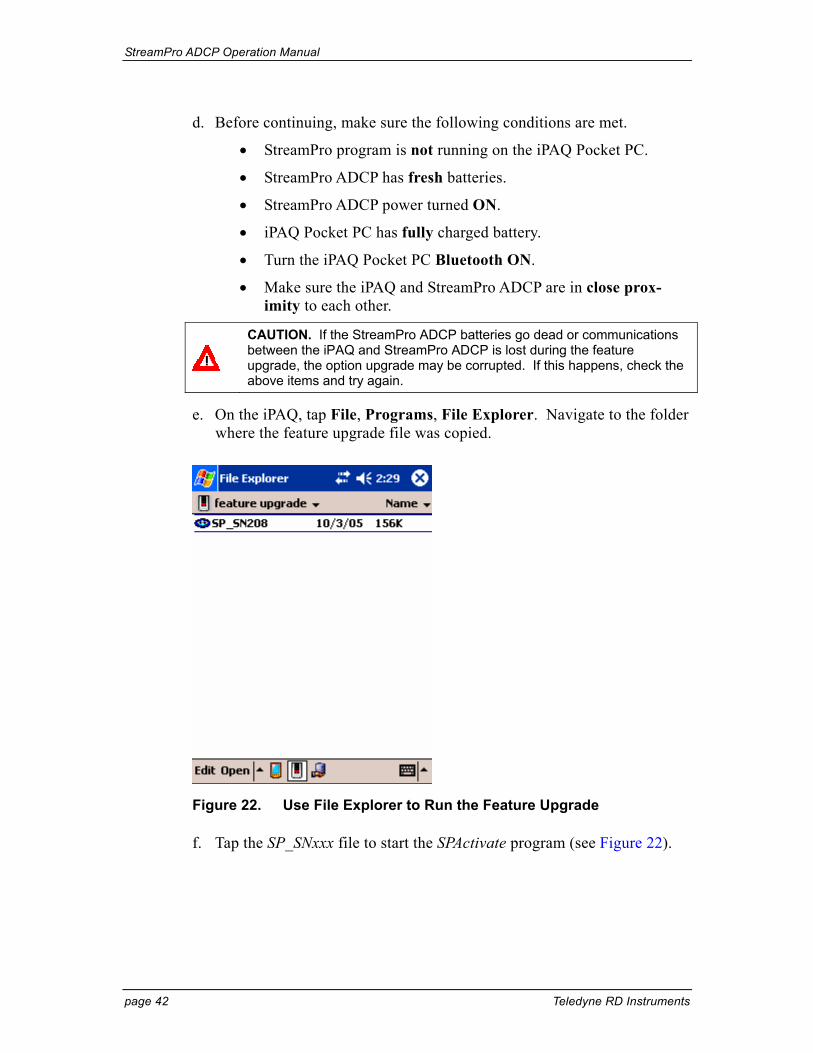
StreamPro ADCP Operation Manual
page 42 Teledyne RD Instruments
d. Before continuing, make sure the following conditions are met.
• StreamPro program is not running on the iPAQ Pocket PC.
• StreamPro ADCP has fresh batteries.
• StreamPro ADCP power turned ON.
• iPAQ Pocket PC has fully charged battery.
• Turn the iPAQ Pocket PC Bluetooth ON.
• Make sure the iPAQ and StreamPro ADCP are in close prox-imity to each other.
CAUTION. If the StreamPro ADCP batteries go dead or communications between the iPAQ and StreamPro ADCP is lost during the feature upgrade, the option upgrade may be corrupted. If this happens, check the above items and try again.
e. On the iPAQ, tap File, Programs, File Explorer. Navigate to the folder where the feature upgrade file was copied.
Figure 22. Use File Explorer to Run the Feature Upgrade
f. Tap the SP_SNxxx file to start the SPActivate program (see Figure 22).

StreamPro ADCP Operation Manual
P/N 95B-6003-00 (February 2008) page 43
Tap this Xto exit!
Figure 23. Feature Enable Program
g. Wait for the Long Range Option Enabled message (see Figure 23). Click OK to continue.
h. Click the X button to exit the SPActivate program. Make sure to click the X, not the white circle with the X (this only minimizes the program). If SPActivate is not exited, the COM port will be still in use and not available for use with the StreamPro software.
i. Start the StreamPro program and test the communications between the iPAQ and StreamPro ADCP. If you have problems, do a soft reset on the iPAQ and try again.
StreamPro ADCP Operation Manual
page 44 Teledyne RD Instruments
9.4 Command Descriptions Each listing includes the command’s purpose, format, default setting (if ap-plicable) range, recommended setting, and description. When appropriate, we include amplifying notes and examples. If a numeric value follows the command, the StreamPro uses it to set a processing value (time, range, per-centage, processing flags). All measurement values are in metric units (mm, cm, and dm).
9.4.1 Miscellaneous Commands
? – Help Menus Purpose Lists the major help groups.
Format x? (see description)
Description Entering a “?” by itself displays all command groups. To dis-play help for one command group, enter x?, where x is the command group you wish to view. When the StreamPro dis-plays the help for a command group, it also shows the format and present setting of those commands. To see the help or set-ting for one command, enter the command followed by a ques-tion mark. For example, to view the CB-command setting en-ter CB?.
Examples See below. >? Available Commands: C ---------- Control E ---------- Environment P ---------- Performance T ---------- Time W ---------- Water Profiling ? ---------- This Menu
StreamPro ADCP Operation Manual
P/N 95B-6003-00 (February 2008) page 45
9.4.2 Control System Commands The StreamPro uses the following commands to control certain system pa-rameters.
CK - Keep Parameters Purpose Stores present parameters to non-volatile memory.
Format CK
Recommended Setting. Use as needed.
Description CK saves the present user command parameters to non-volatile memory on the CPU board. The StreamPro maintains data stored in the non-volatile memory (user settings) even if power is lost. It does not need a battery. You can recall pa-rameters stored in non-volatile memory with the CR0-command.
CR – Retrieve Parameters Purpose Resets the StreamPro command set to factory settings.
Format CRn
Range n = 0 (User), 1 (Factory)
Recommended Setting. Use as needed.
Description The StreamPro automatically stores the last set of commands used in RAM. The StreamPro will continue to be configured from RAM unless it receives a CR-command or until the RAM loses its power.
Table 5: Retrieve Parameters Format Description
CR0 Loads into RAM the command set last stored in non-volatile memory (user settings) using the CK-Command.
CR1 Loads into RAM the factory default command set stored in ROM (factory settings).
StreamPro ADCP Operation Manual
page 46 Teledyne RD Instruments
CS – Start Pinging (Go) Purpose Starts the data collection cycle.
Format CS
Recommended Setting. Use as needed. Use WinRiver to create the command file. The CS command will be added to the end of the command file or sent by the software.
Description Use CS to tell the StreamPro to start pinging its transducers and collecting data as programmed by the other commands.
NOTE. After a CS-command is sent to the StreamPro, no changes to the commands can occur until a = = = is sent.
StreamPro ADCP Operation Manual
P/N 95B-6003-00 (February 2008) page 47
9.4.3 Environmental Commands The StreamPro uses the following commands to control the environmental and positional information that affects internal data processing.
EC - Speed of Sound Purpose Sets the speed of sound value used for ADCP data processing.
Format ECnnnn
Range nnnn = 1400 to 1600 meters per second
Default EC1500
Recommended Setting. The default setting for this command is recommended for most applications.
Description EC sets the sound speed value used by the ADCP to scale ve-locity data, depth cell size, and range to the bottom. The ADCP assumes the speed of sound reading is taken at the transducer head. See the primer for information on speed of sound calculations.
NOTE. If the EZ Speed of Sound field = 1, the ADCP overrides the manually-set EC value and calculates speed of sound using the values determined by transducer depth (ED), salinity (ES), and transducer temperature (ET). EZ also selects the source for ED, ES, and ET.
ES – Salinity Purpose Sets the water’s salinity value.
Format ESnn
Range nn = 0 to 40
Default ES0
Recommended Setting. The default setting for this command is recommended for most applications.
Description ES sets the water’s salinity value. The StreamPro uses ES in its speed of sound calculations. The StreamPro assumes the speed of sound reading is taken at the transducer head.
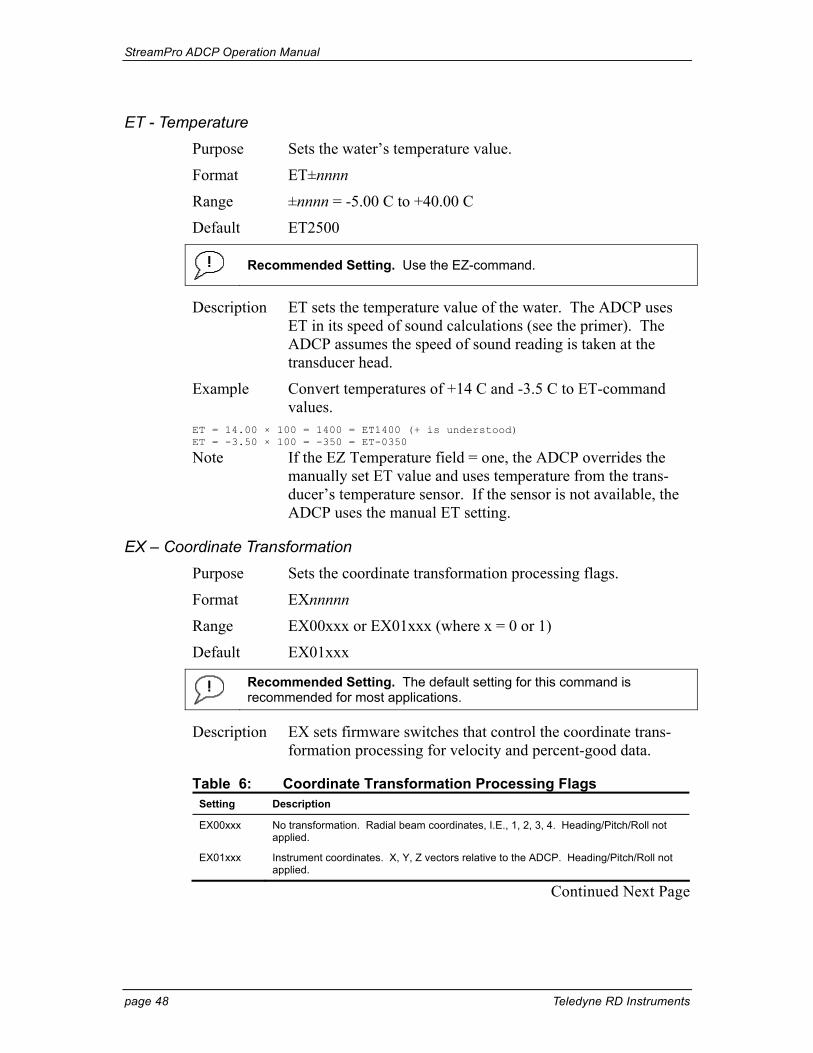
StreamPro ADCP Operation Manual
page 48 Teledyne RD Instruments
ET - Temperature Purpose Sets the water’s temperature value.
Format ET±nnnn
Range ±nnnn = -5.00 C to +40.00 C
Default ET2500
Recommended Setting. Use the EZ-command.
Description ET sets the temperature value of the water. The ADCP uses ET in its speed of sound calculations (see the primer). The ADCP assumes the speed of sound reading is taken at the transducer head.
Example Convert temperatures of +14 C and -3.5 C to ET-command values.
ET = 14.00 × 100 = 1400 = ET1400 (+ is understood) ET = -3.50 × 100 = -350 = ET-0350
Note If the EZ Temperature field = one, the ADCP overrides the manually set ET value and uses temperature from the trans-ducer’s temperature sensor. If the sensor is not available, the ADCP uses the manual ET setting.
EX – Coordinate Transformation Purpose Sets the coordinate transformation processing flags.
Format EXnnnnn
Range EX00xxx or EX01xxx (where x = 0 or 1)
Default EX01xxx
Recommended Setting. The default setting for this command is recommended for most applications.
Description EX sets firmware switches that control the coordinate trans-formation processing for velocity and percent-good data.
Table 6: Coordinate Transformation Processing Flags Setting Description
EX00xxx No transformation. Radial beam coordinates, I.E., 1, 2, 3, 4. Heading/Pitch/Roll not applied.
EX01xxx Instrument coordinates. X, Y, Z vectors relative to the ADCP. Heading/Pitch/Roll not applied.
Continued Next Page
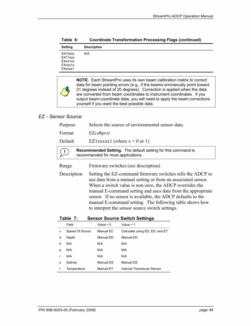
StreamPro ADCP Operation Manual
P/N 95B-6003-00 (February 2008) page 49
Table 6: Coordinate Transformation Processing Flags (continued) Setting Description
EX10xxx EX11xxx EXxx1xx EXxxx1x EXxxxx1
N/A
NOTE. Each StreamPro uses its own beam calibration matrix to correct data for beam pointing errors (e.g., if the beams erroneously point toward 21 degrees instead of 20 degrees). Correction is applied when the data are converted from beam coordinates to instrument coordinates. If you output beam-coordinate data, you will need to apply the beam corrections yourself if you want the best possible data.
EZ - Sensor Source Purpose Selects the source of environmental sensor data.
Format EZcdhprst
Default EZ1xxxxx1 (where x = 0 or 1)
Recommended Setting. The default setting for this command is recommended for most applications.
Range Firmware switches (see description)
Description Setting the EZ-command firmware switches tells the ADCP to use data from a manual setting or from an associated sensor. When a switch value is non-zero, the ADCP overrides the manual E-command setting and uses data from the appropriate sensor. If no sensor is available, the ADCP defaults to the manual E-command setting. The following table shows how to interpret the sensor source switch settings.
Table 7: Sensor Source Switch Settings Field Value = 0 Value = 1
c Speed Of Sound Manual EC Calculate using ED, ES, and ET
d Depth Manual ED Manual ED
h N/A N/A N/A
p N/A N/A N/A
r N/A N/A N/A
s Salinity Manual ES Manual ES
t Temperature Manual ET Internal Transducer Sensor
StreamPro ADCP Operation Manual
page 50 Teledyne RD Instruments
9.4.4 Performance and Testing Commands The StreamPro uses the following commands for calibration and testing.
PS – Display System Parameters Purpose Sends/displays StreamPro system configuration data.
Format PSn
Range n = 0, 3 (see description)
Recommended Setting. Use as needed.
Description See below.
PS0 – System Configuration PS0 sends the StreamPro hardware/firmware information. For example, the output may look like this: >PS0 Serial Number: 208 Frequency: 2000000 HZ Configuration: 4 BM, JANUS Beam Angle: 20 DEGREES CPU Firmware: 31.03h FPGA Version: 2.00.003 ROM_ID: E7 00 00 00 3D 68 96 28 Part Num: ROM_ID: 1C 00 00 00 0E 91 B4 23 Part Num: XDR82B-1003-0XC ROM_ID: 21 00 00 00 22 3A 46 23 Part Num: PIO72B-2001-12X ROM_ID: C3 00 00 00 22 6A 15 23 Part Num: DSP72B-2002-12X ROM_ID: 2C 00 00 00 10 B4 B5 23 Part Num: PER72B-2006-00A ROM_ID: E8 00 00 00 0E 97 83 23 Part Num: RCV72B-2003-12A >
PS3 – Instrument Transformation Matrix PS3 sends information about the transducer beams. The StreamPro uses this information in its coordinate-transformation calculations; for example, the output may look like this: >ps3 -1.4619 1.4619 0.0000 0.0000 0.0000 0.0000 -1.4619 1.4619 0.2660 0.2660 0.2660 0.2660 1.0337 1.0337 1.0337 1.0337
If the StreamPro has beam angle errors, they are reflected in the instrument transformation matrix. This matrix, when multiplied by the raw beam data gives currents in the x, y, z, and e directions.
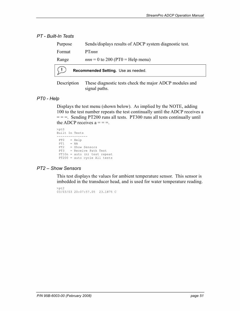
StreamPro ADCP Operation Manual
P/N 95B-6003-00 (February 2008) page 51
PT - Built-In Tests Purpose Sends/displays results of ADCP system diagnostic test.
Format PTnnn
Range nnn = 0 to 200 (PT0 = Help menu)
Recommended Setting. Use as needed.
Description These diagnostic tests check the major ADCP modules and signal paths.
PT0 - Help Displays the test menu (shown below). As implied by the NOTE, adding 100 to the test number repeats the test continually until the ADCP receives a = = =. Sending PT200 runs all tests. PT300 runs all tests continually until the ADCP receives a = = =. >pt0 Built In Tests ---------------- PT0 = Help PT1 = NA PT2 = Show Sensors PT3 = Receive Path Test PT10n = auto (n) test repeat PT200 = auto cycle All tests
PT2 – Show Sensors This test displays the values for ambient temperature sensor. This sensor is imbedded in the transducer head, and is used for water temperature reading. >pt2 03/03/03 20:07:57.05 23.1875 C
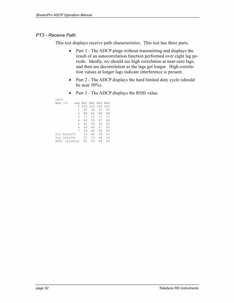
StreamPro ADCP Operation Manual
page 52 Teledyne RD Instruments
PT3 - Receive Path This test displays receive path characteristics. This test has three parts.
• Part 1 - The ADCP pings without transmitting and displays the result of an autocorrelation function performed over eight lag pe-riods. Ideally, we should see high correlation at near-zero lags, and then see decorrelation as the lags get longer. High correla-tion values at longer lags indicate interference is present.
• Part 2 - The ADCP displays the hard limited duty cycle (should be near 50%).
• Part 3 - The ADCP displays the RSSI value. >pt3 Mag (%) Lag Bm1 Bm2 Bm3 Bm4 0 100 100 100 100 1 97 96 97 97 2 88 86 88 88 3 77 72 77 77 4 66 59 67 68 5 61 50 60 63 6 58 46 57 60 7 58 44 56 59 Sin Duty(%) 33 42 39 41 Cos Duty(%) 21 19 18 16 RSSI (counts) 65 60 69 65
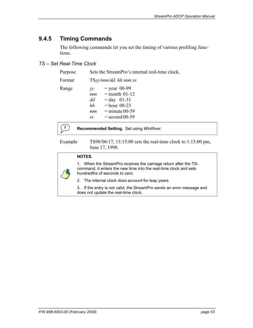
StreamPro ADCP Operation Manual
P/N 95B-6003-00 (February 2008) page 53
9.4.5 Timing Commands The following commands let you set the timing of various profiling func-tions.
TS – Set Real-Time Clock Purpose Sets the StreamPro’s internal real-time clock.
Format TSyy/mm/dd, hh:mm:ss
Range yy = year 00-99 mm = month 01-12 dd = day 01-31 hh = hour 00-23 mm = minute 00-59 ss = second 00-59
Recommended Setting. Set using WinRiver.
Example TS98/06/17, 13:15:00 sets the real-time clock to 1:15:00 pm, June 17, 1998.
NOTES.
1. When the StreamPro receives the carriage return after the TS-command, it enters the new time into the real-time clock and sets hundredths of seconds to zero.
2. The internal clock does account for leap years.
3. If the entry is not valid, the StreamPro sends an error message and does not update the real-time clock.
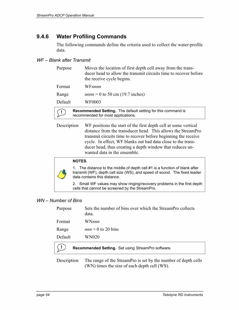
StreamPro ADCP Operation Manual
page 54 Teledyne RD Instruments
9.4.6 Water Profiling Commands The following commands define the criteria used to collect the water-profile data.
WF – Blank after Transmit Purpose Moves the location of first depth cell away from the trans-
ducer head to allow the transmit circuits time to recover before the receive cycle begins.
Format WFnnnn
Range nnnn = 0 to 50 cm (19.7 inches)
Default WF0003
Recommended Setting. The default setting for this command is recommended for most applications.
Description WF positions the start of the first depth cell at some vertical distance from the transducer head. This allows the StreamPro transmit circuits time to recover before beginning the receive cycle. In effect, WF blanks out bad data close to the trans-ducer head, thus creating a depth window that reduces un-wanted data in the ensemble.
NOTES.
1. The distance to the middle of depth cell #1 is a function of blank after transmit (WF), depth cell size (WS), and speed of sound. The fixed leader data contains this distance.
2. Small WF values may show ringing/recovery problems in the first depth cells that cannot be screened by the StreamPro.
WN – Number of Bins Purpose Sets the number of bins over which the StreamPro collects
data.
Format WNnnn
Range nnn = 0 to 20 bins
Default WN020
Recommended Setting. Set using StreamPro software.
Description The range of the StreamPro is set by the number of depth cells (WN) times the size of each depth cell (WS).
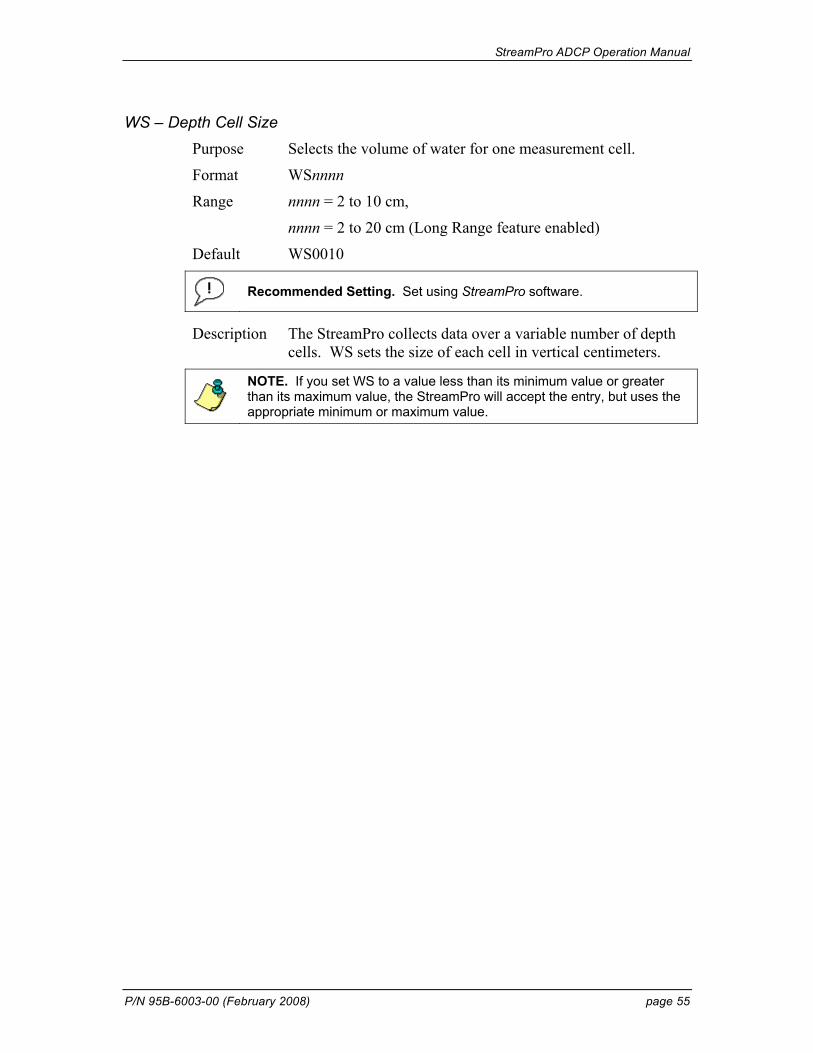
StreamPro ADCP Operation Manual
P/N 95B-6003-00 (February 2008) page 55
WS – Depth Cell Size Purpose Selects the volume of water for one measurement cell.
Format WSnnnn
Range nnnn = 2 to 10 cm,
nnnn = 2 to 20 cm (Long Range feature enabled)
Default WS0010
Recommended Setting. Set using StreamPro software.
Description The StreamPro collects data over a variable number of depth cells. WS sets the size of each cell in vertical centimeters.
NOTE. If you set WS to a value less than its minimum value or greater than its maximum value, the StreamPro will accept the entry, but uses the appropriate minimum or maximum value.
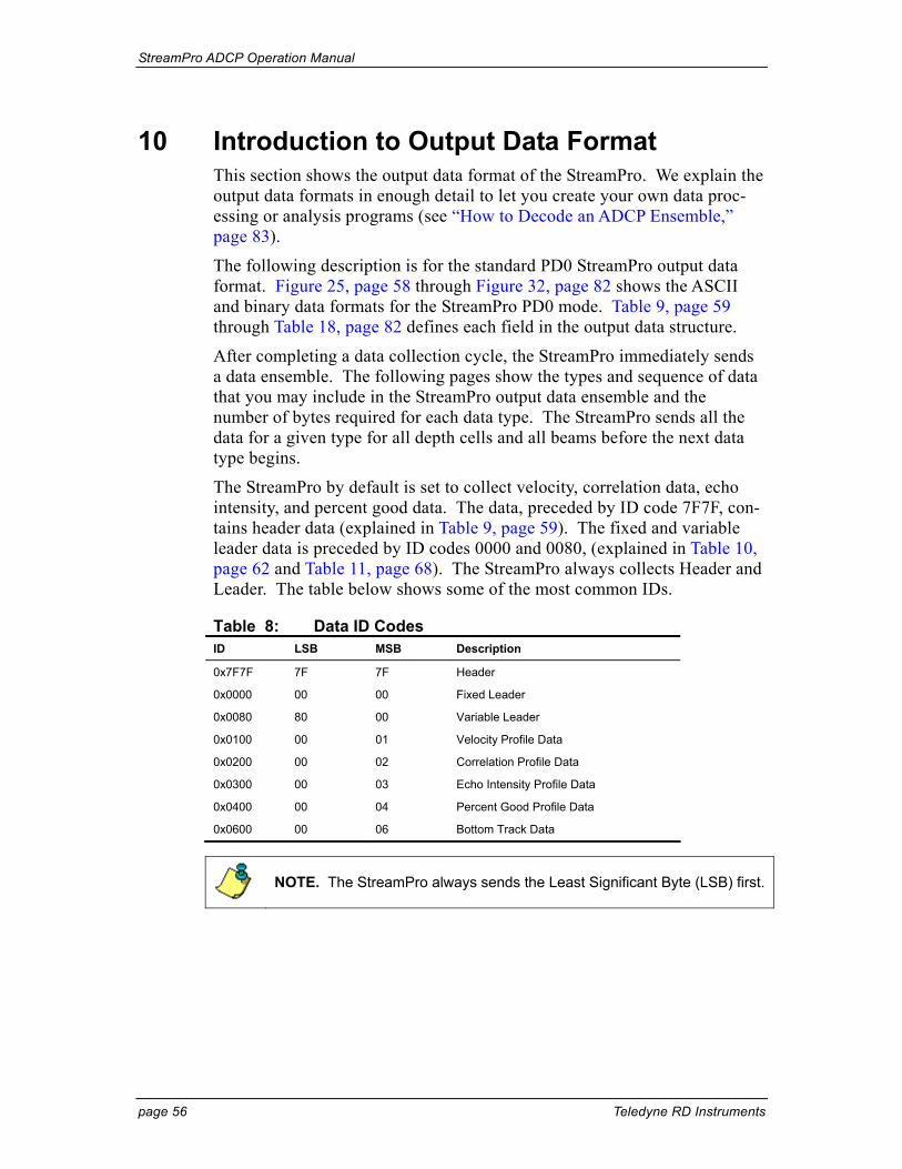
StreamPro ADCP Operation Manual
page 56 Teledyne RD Instruments
10 Introduction to Output Data Format This section shows the output data format of the StreamPro. We explain the output data formats in enough detail to let you create your own data proc-essing or analysis programs (see “How to Decode an ADCP Ensemble,” page 83).
The following description is for the standard PD0 StreamPro output data format. Figure 25, page 58 through Figure 32, page 82 shows the ASCII and binary data formats for the StreamPro PD0 mode. Table 9, page 59 through Table 18, page 82 defines each field in the output data structure.
After completing a data collection cycle, the StreamPro immediately sends a data ensemble. The following pages show the types and sequence of data that you may include in the StreamPro output data ensemble and the number of bytes required for each data type. The StreamPro sends all the data for a given type for all depth cells and all beams before the next data type begins.
The StreamPro by default is set to collect velocity, correlation data, echo intensity, and percent good data. The data, preceded by ID code 7F7F, con-tains header data (explained in Table 9, page 59). The fixed and variable leader data is preceded by ID codes 0000 and 0080, (explained in Table 10, page 62 and Table 11, page 68). The StreamPro always collects Header and Leader. The table below shows some of the most common IDs.
Table 8: Data ID Codes ID LSB MSB Description
0x7F7F 7F 7F Header
0x0000 00 00 Fixed Leader
0x0080 80 00 Variable Leader
0x0100 00 01 Velocity Profile Data
0x0200 00 02 Correlation Profile Data
0x0300 00 03 Echo Intensity Profile Data
0x0400 00 04 Percent Good Profile Data
0x0600 00 06 Bottom Track Data
NOTE. The StreamPro always sends the Least Significant Byte (LSB) first.
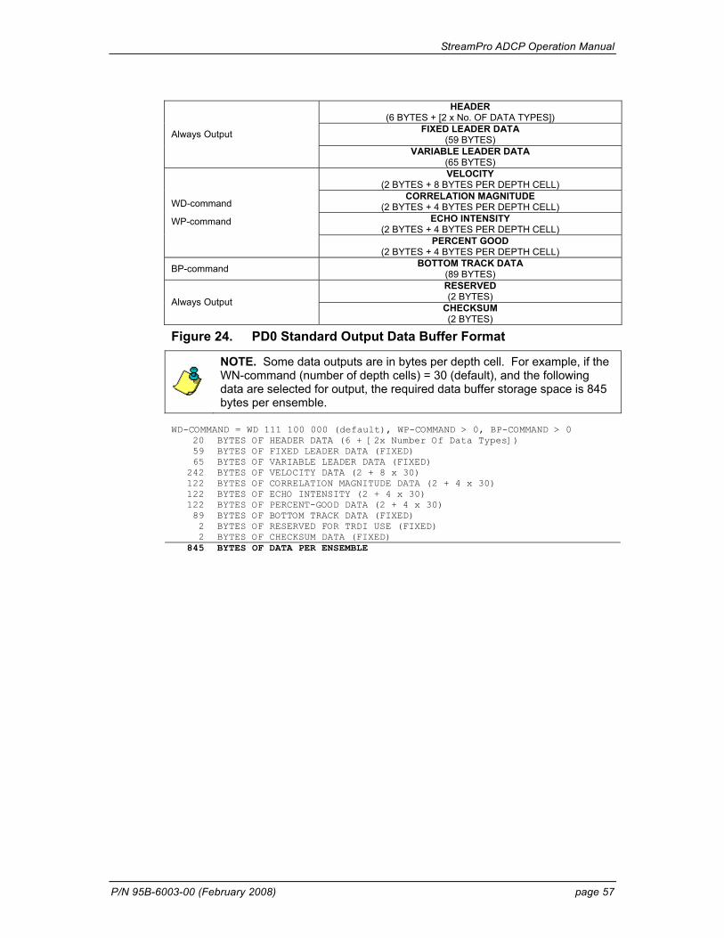
StreamPro ADCP Operation Manual
P/N 95B-6003-00 (February 2008) page 57
HEADER (6 BYTES + [2 x No. OF DATA TYPES])
FIXED LEADER DATA (59 BYTES) Always Output
VARIABLE LEADER DATA (65 BYTES) VELOCITY
(2 BYTES + 8 BYTES PER DEPTH CELL) CORRELATION MAGNITUDE
(2 BYTES + 4 BYTES PER DEPTH CELL) ECHO INTENSITY
(2 BYTES + 4 BYTES PER DEPTH CELL)
WD-command
WP-command
PERCENT GOOD (2 BYTES + 4 BYTES PER DEPTH CELL)
BP-command BOTTOM TRACK DATA (89 BYTES) RESERVED (2 BYTES) Always Output CHECKSUM (2 BYTES)
Figure 24. PD0 Standard Output Data Buffer Format
NOTE. Some data outputs are in bytes per depth cell. For example, if the WN-command (number of depth cells) = 30 (default), and the following data are selected for output, the required data buffer storage space is 845 bytes per ensemble.
WD-COMMAND = WD 111 100 000 (default), WP-COMMAND > 0, BP-COMMAND > 0
20 BYTES OF HEADER DATA (6 + [2x Number Of Data Types]) 59 BYTES OF FIXED LEADER DATA (FIXED) 65 BYTES OF VARIABLE LEADER DATA (FIXED)
242 BYTES OF VELOCITY DATA (2 + 8 x 30) 122 BYTES OF CORRELATION MAGNITUDE DATA (2 + 4 x 30) 122 BYTES OF ECHO INTENSITY (2 + 4 x 30) 122 BYTES OF PERCENT-GOOD DATA (2 + 4 x 30) 89 BYTES OF BOTTOM TRACK DATA (FIXED) 2 BYTES OF RESERVED FOR TRDI USE (FIXED) 2 BYTES OF CHECKSUM DATA (FIXED)
845 BYTES OF DATA PER ENSEMBLE
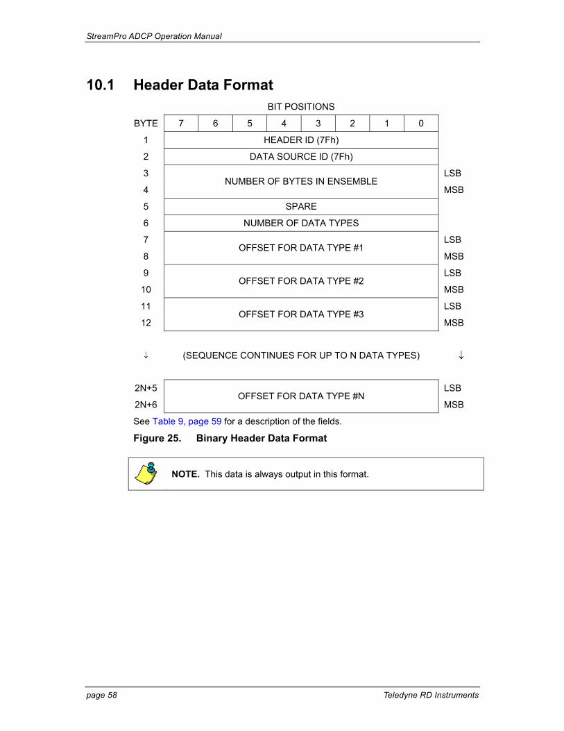
StreamPro ADCP Operation Manual
page 58 Teledyne RD Instruments
10.1 Header Data Format BIT POSITIONS
BYTE 7 6 5 4 3 2 1 0
1 HEADER ID (7Fh)
2 DATA SOURCE ID (7Fh)
3 LSB
4 NUMBER OF BYTES IN ENSEMBLE
MSB
5 SPARE
6 NUMBER OF DATA TYPES
7 LSB
8 OFFSET FOR DATA TYPE #1
MSB
9 LSB
10 OFFSET FOR DATA TYPE #2
MSB
11 LSB
12 OFFSET FOR DATA TYPE #3
MSB
↓ (SEQUENCE CONTINUES FOR UP TO N DATA TYPES) ↓
2N+5 LSB
2N+6 OFFSET FOR DATA TYPE #N
MSB
See Table 9, page 59 for a description of the fields.
Figure 25. Binary Header Data Format
NOTE. This data is always output in this format.
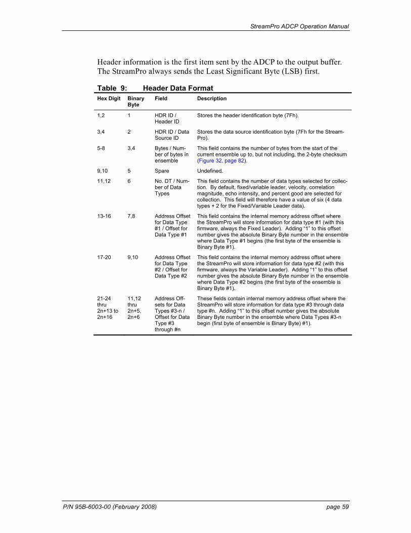
StreamPro ADCP Operation Manual
P/N 95B-6003-00 (February 2008) page 59
Header information is the first item sent by the ADCP to the output buffer. The StreamPro always sends the Least Significant Byte (LSB) first.
Table 9: Header Data Format Hex Digit Binary
Byte Field Description
1,2 1 HDR ID / Header ID
Stores the header identification byte (7Fh).
3,4 2 HDR ID / Data Source ID
Stores the data source identification byte (7Fh for the Stream-Pro).
5-8 3,4 Bytes / Num-ber of bytes in ensemble
This field contains the number of bytes from the start of the current ensemble up to, but not including, the 2-byte checksum (Figure 32, page 82).
9,10 5 Spare Undefined.
11,12 6 No. DT / Num-ber of Data Types
This field contains the number of data types selected for collec-tion. By default, fixed/variable leader, velocity, correlation magnitude, echo intensity, and percent good are selected for collection. This field will therefore have a value of six (4 data types + 2 for the Fixed/Variable Leader data).
13-16 7,8 Address Offset for Data Type #1 / Offset for Data Type #1
This field contains the internal memory address offset where the StreamPro will store information for data type #1 (with this firmware, always the Fixed Leader). Adding “1” to this offset number gives the absolute Binary Byte number in the ensemble where Data Type #1 begins (the first byte of the ensemble is Binary Byte #1).
17-20 9,10 Address Offset for Data Type #2 / Offset for Data Type #2
This field contains the internal memory address offset where the StreamPro will store information for data type #2 (with this firmware, always the Variable Leader). Adding “1” to this offset number gives the absolute Binary Byte number in the ensemble where Data Type #2 begins (the first byte of the ensemble is Binary Byte #1).
21-24 thru 2n+13 to 2n+16
11,12 thru 2n+5, 2n+6
Address Off-sets for Data Types #3-n / Offset for Data Type #3 through #n
These fields contain internal memory address offset where the StreamPro will store information for data type #3 through data type #n. Adding “1” to this offset number gives the absolute Binary Byte number in the ensemble where Data Types #3-n begin (first byte of ensemble is Binary Byte) #1).
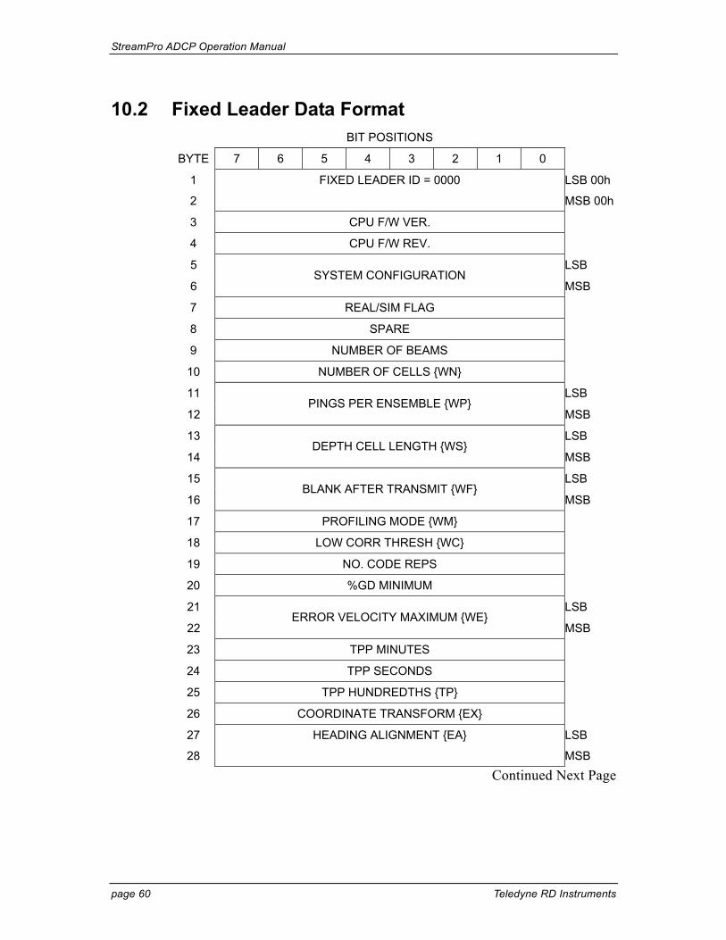
StreamPro ADCP Operation Manual
page 60 Teledyne RD Instruments
10.2 Fixed Leader Data Format BIT POSITIONS
BYTE 7 6 5 4 3 2 1 0
1 FIXED LEADER ID = 0000 LSB 00h
2 MSB 00h
3 CPU F/W VER.
4 CPU F/W REV.
5 LSB
6 SYSTEM CONFIGURATION
MSB
7 REAL/SIM FLAG
8 SPARE
9 NUMBER OF BEAMS
10 NUMBER OF CELLS {WN}
11 LSB
12 PINGS PER ENSEMBLE {WP}
MSB
13 LSB
14 DEPTH CELL LENGTH {WS}
MSB
15 LSB
16 BLANK AFTER TRANSMIT {WF}
MSB
17 PROFILING MODE {WM}
18 LOW CORR THRESH {WC}
19 NO. CODE REPS
20 %GD MINIMUM
21 LSB
22 ERROR VELOCITY MAXIMUM {WE}
MSB
23 TPP MINUTES
24 TPP SECONDS
25 TPP HUNDREDTHS {TP}
26 COORDINATE TRANSFORM {EX}
27 HEADING ALIGNMENT {EA} LSB
28 MSB
Continued Next Page
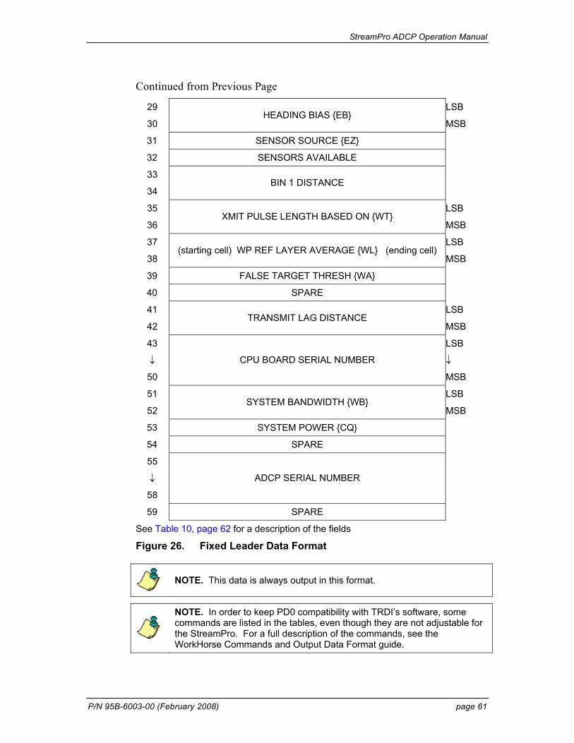
StreamPro ADCP Operation Manual
P/N 95B-6003-00 (February 2008) page 61
Continued from Previous Page
29 LSB
30 HEADING BIAS {EB}
MSB
31 SENSOR SOURCE {EZ}
32 SENSORS AVAILABLE
33
34 BIN 1 DISTANCE
35 LSB
36 XMIT PULSE LENGTH BASED ON {WT}
MSB
37 LSB
38 (starting cell) WP REF LAYER AVERAGE {WL} (ending cell)
MSB
39 FALSE TARGET THRESH {WA}
40 SPARE
41 LSB
42 TRANSMIT LAG DISTANCE
MSB
43 LSB
↓ ↓
50
CPU BOARD SERIAL NUMBER
MSB
51 LSB
52 SYSTEM BANDWIDTH {WB}
MSB
53 SYSTEM POWER {CQ}
54 SPARE
55
↓
58
ADCP SERIAL NUMBER
59 SPARE
See Table 10, page 62 for a description of the fields
Figure 26. Fixed Leader Data Format
NOTE. This data is always output in this format.
NOTE. In order to keep PD0 compatibility with TRDI’s software, some commands are listed in the tables, even though they are not adjustable for the StreamPro. For a full description of the commands, see the WorkHorse Commands and Output Data Format guide.
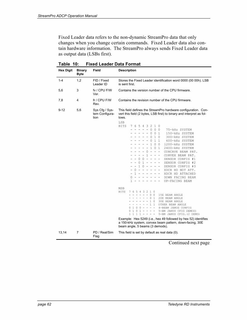
StreamPro ADCP Operation Manual
page 62 Teledyne RD Instruments
Fixed Leader data refers to the non-dynamic StreamPro data that only changes when you change certain commands. Fixed Leader data also con-tain hardware information. The StreamPro always sends Fixed Leader data as output data (LSBs first).
Table 10: Fixed Leader Data Format Hex Digit Binary
Byte Field Description
1-4 1,2 FID / Fixed Leader ID
Stores the Fixed Leader identification word 0000 (00 00h). LSB is sent first.
5,6 3 fv / CPU F/W Ver.
Contains the version number of the CPU firmware.
7,8 4 fr / CPU F/W Rev.
Contains the revision number of the CPU firmware.
9-12 5,6 Sys Cfg / Sys-tem Configura-tion
This field defines the StreamPro hardware configuration. Con-vert this field (2 bytes, LSB first) to binary and interpret as fol-lows. LSB BITS 7 6 5 4 3 2 1 0 - - - - - 0 0 0 75-kHz SYSTEM - - - - - 0 0 1 150-kHz SYSTEM - - - - - 0 1 0 300-kHz SYSTEM - - - - - 0 1 1 600-kHz SYSTEM - - - - - 1 0 0 1200-kHz SYSTEM - - - - - 1 0 1 2400-kHz SYSTEM - - - - 0 - - - CONCAVE BEAM PAT. - - - - 1 - - - CONVEX BEAM PAT. - - 0 0 - - - - SENSOR CONFIG #1 - - 0 1 - - - - SENSOR CONFIG #2 - - 1 0 - - - - SENSOR CONFIG #3 - 0 - - - - - - XDCR HD NOT ATT. - 1 - - - - - - XDCR HD ATTACHED 0 - - - - - - - DOWN FACING BEAM 1 - - - - - - - UP-FACING BEAM MSB BITS 7 6 5 4 3 2 1 0 - - - - - - 0 0 15E BEAM ANGLE - - - - - - 0 1 20E BEAM ANGLE - - - - - - 1 0 30E BEAM ANGLE - - - - - - 1 1 OTHER BEAM ANGLE 0 1 0 0 - - - - 4-BEAM JANUS CONFIG 0 1 0 1 - - - - 5-BM JANUS CFIG DEMOD) 1 1 1 1 - - - - 5-BM JANUS CFIG.(2 DEMD)
Example: Hex 5249 (i.e., hex 49 followed by hex 52) identifies a 150-kHz system, convex beam pattern, down-facing, 30E beam angle, 5 beams (3 demods).
13,14 7 PD / Real/Sim Flag
This field is set by default as real data (0).
Continued next page
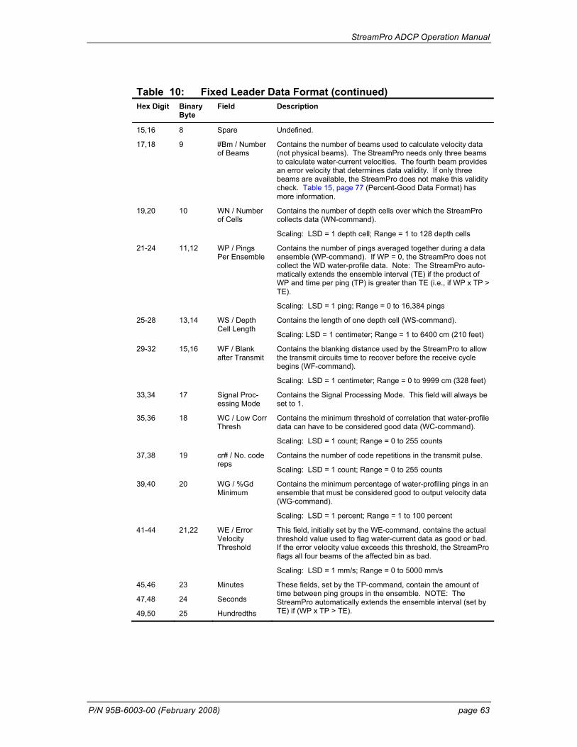
StreamPro ADCP Operation Manual
P/N 95B-6003-00 (February 2008) page 63
Table 10: Fixed Leader Data Format (continued) Hex Digit Binary
Byte Field Description
15,16 8 Spare Undefined.
17,18 9 #Bm / Number of Beams
Contains the number of beams used to calculate velocity data (not physical beams). The StreamPro needs only three beams to calculate water-current velocities. The fourth beam provides an error velocity that determines data validity. If only three beams are available, the StreamPro does not make this validity check. Table 15, page 77 (Percent-Good Data Format) has more information.
19,20 10 WN / Number of Cells
Contains the number of depth cells over which the StreamPro collects data (WN-command).
Scaling: LSD = 1 depth cell; Range = 1 to 128 depth cells
21-24 11,12 WP / Pings Per Ensemble
Contains the number of pings averaged together during a data ensemble (WP-command). If WP = 0, the StreamPro does not collect the WD water-profile data. Note: The StreamPro auto-matically extends the ensemble interval (TE) if the product of WP and time per ping (TP) is greater than TE (i.e., if WP x TP > TE).
Scaling: LSD = 1 ping; Range = 0 to 16,384 pings
25-28 13,14 WS / Depth Cell Length
Contains the length of one depth cell (WS-command).
Scaling: LSD = 1 centimeter; Range = 1 to 6400 cm (210 feet)
29-32 15,16 WF / Blank after Transmit
Contains the blanking distance used by the StreamPro to allow the transmit circuits time to recover before the receive cycle begins (WF-command).
Scaling: LSD = 1 centimeter; Range = 0 to 9999 cm (328 feet)
33,34 17 Signal Proc-essing Mode
Contains the Signal Processing Mode. This field will always be set to 1.
35,36 18 WC / Low Corr Thresh
Contains the minimum threshold of correlation that water-profile data can have to be considered good data (WC-command).
Scaling: LSD = 1 count; Range = 0 to 255 counts
37,38 19 cr# / No. code reps
Contains the number of code repetitions in the transmit pulse.
Scaling: LSD = 1 count; Range = 0 to 255 counts
39,40 20 WG / %Gd Minimum
Contains the minimum percentage of water-profiling pings in an ensemble that must be considered good to output velocity data (WG-command).
Scaling: LSD = 1 percent; Range = 1 to 100 percent
41-44 21,22 WE / Error Velocity Threshold
This field, initially set by the WE-command, contains the actual threshold value used to flag water-current data as good or bad. If the error velocity value exceeds this threshold, the StreamPro flags all four beams of the affected bin as bad.
Scaling: LSD = 1 mm/s; Range = 0 to 5000 mm/s
45,46
47,48
49,50
23
24
25
Minutes
Seconds
Hundredths
These fields, set by the TP-command, contain the amount of time between ping groups in the ensemble. NOTE: The StreamPro automatically extends the ensemble interval (set by TE) if (WP x TP > TE).
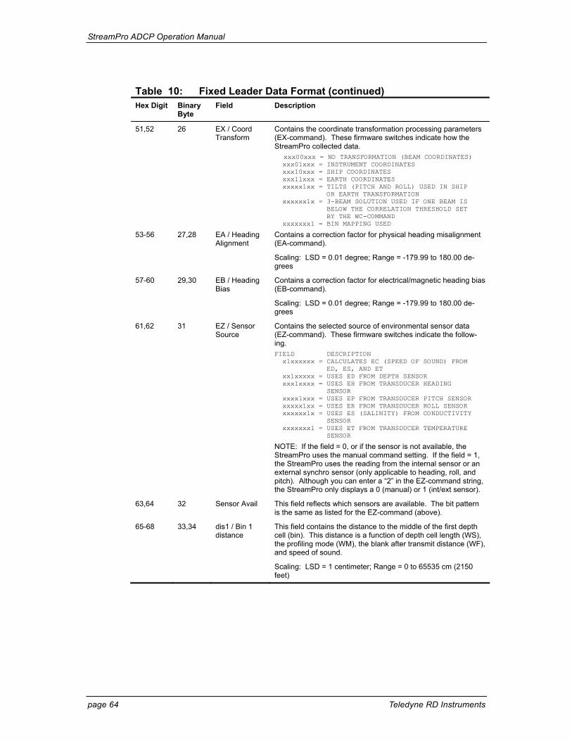
StreamPro ADCP Operation Manual
page 64 Teledyne RD Instruments
Table 10: Fixed Leader Data Format (continued) Hex Digit Binary
Byte Field Description
51,52 26 EX / Coord Transform
Contains the coordinate transformation processing parameters (EX-command). These firmware switches indicate how the StreamPro collected data. xxx00xxx = NO TRANSFORMATION (BEAM COORDINATES) xxx01xxx = INSTRUMENT COORDINATES xxx10xxx = SHIP COORDINATES xxx11xxx = EARTH COORDINATES xxxxx1xx = TILTS (PITCH AND ROLL) USED IN SHIP OR EARTH TRANSFORMATION xxxxxx1x = 3-BEAM SOLUTION USED IF ONE BEAM IS BELOW THE CORRELATION THRESHOLD SET BY THE WC-COMMAND xxxxxxx1 = BIN MAPPING USED
53-56 27,28 EA / Heading Alignment
Contains a correction factor for physical heading misalignment (EA-command).
Scaling: LSD = 0.01 degree; Range = -179.99 to 180.00 de-grees
57-60 29,30 EB / Heading Bias
Contains a correction factor for electrical/magnetic heading bias (EB-command).
Scaling: LSD = 0.01 degree; Range = -179.99 to 180.00 de-grees
61,62 31 EZ / Sensor Source
Contains the selected source of environmental sensor data (EZ-command). These firmware switches indicate the follow-ing. FIELD DESCRIPTION x1xxxxxx = CALCULATES EC (SPEED OF SOUND) FROM ED, ES, AND ET xx1xxxxx = USES ED FROM DEPTH SENSOR xxx1xxxx = USES EH FROM TRANSDUCER HEADING SENSOR xxxx1xxx = USES EP FROM TRANSDUCER PITCH SENSOR xxxxx1xx = USES ER FROM TRANSDUCER ROLL SENSOR xxxxxx1x = USES ES (SALINITY) FROM CONDUCTIVITY SENSOR xxxxxxx1 = USES ET FROM TRANSDUCER TEMPERATURE SENSOR
NOTE: If the field = 0, or if the sensor is not available, the StreamPro uses the manual command setting. If the field = 1, the StreamPro uses the reading from the internal sensor or an external synchro sensor (only applicable to heading, roll, and pitch). Although you can enter a “2” in the EZ-command string, the StreamPro only displays a 0 (manual) or 1 (int/ext sensor).
63,64 32 Sensor Avail This field reflects which sensors are available. The bit pattern is the same as listed for the EZ-command (above).
65-68 33,34 dis1 / Bin 1 distance
This field contains the distance to the middle of the first depth cell (bin). This distance is a function of depth cell length (WS), the profiling mode (WM), the blank after transmit distance (WF), and speed of sound.
Scaling: LSD = 1 centimeter; Range = 0 to 65535 cm (2150 feet)
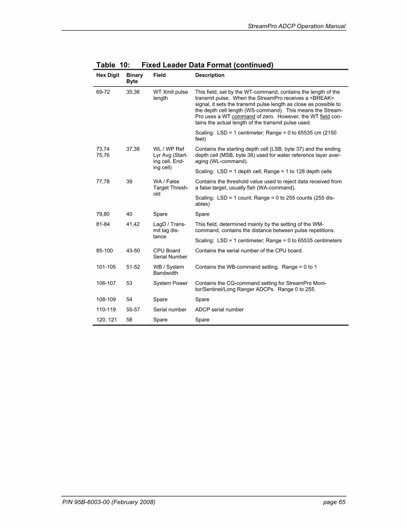
StreamPro ADCP Operation Manual
P/N 95B-6003-00 (February 2008) page 65
Table 10: Fixed Leader Data Format (continued) Hex Digit Binary
Byte Field Description
69-72 35,36 WT Xmit pulse length
This field, set by the WT-command, contains the length of the transmit pulse. When the StreamPro receives a <BREAK> signal, it sets the transmit pulse length as close as possible to the depth cell length (WS-command). This means the Stream-Pro uses a WT command of zero. However, the WT field con-tains the actual length of the transmit pulse used.
Scaling: LSD = 1 centimeter; Range = 0 to 65535 cm (2150 feet)
73,74 75,76
37,38 WL / WP Ref Lyr Avg (Start-ing cell, End-ing cell)
Contains the starting depth cell (LSB, byte 37) and the ending depth cell (MSB, byte 38) used for water reference layer aver-aging (WL-command).
Scaling: LSD = 1 depth cell; Range = 1 to 128 depth cells
77,78 39 WA / False Target Thresh-old
Contains the threshold value used to reject data received from a false target, usually fish (WA-command).
Scaling: LSD = 1 count; Range = 0 to 255 counts (255 dis-ables)
79,80 40 Spare Spare
81-84 41,42 LagD / Trans-mit lag dis-tance
This field, determined mainly by the setting of the WM-command, contains the distance between pulse repetitions.
Scaling: LSD = 1 centimeter; Range = 0 to 65535 centimeters
85-100 43-50 CPU Board Serial Number
Contains the serial number of the CPU board.
101-105 51-52 WB / System Bandwidth
Contains the WB-command setting. Range = 0 to 1
106-107 53 System Power Contains the CQ-command setting for StreamPro Moni-tor/Sentinel/Long Ranger ADCPs. Range 0 to 255.
108-109 54 Spare Spare
110-119 55-57 Serial number ADCP serial number
120, 121 58 Spare Spare
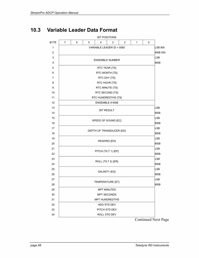
StreamPro ADCP Operation Manual
page 66 Teledyne RD Instruments
10.3 Variable Leader Data Format BIT POSITIONS
BYTE 7 6 5 4 3 2 1 0
1 VARIABLE LEADER ID = 0080 LSB 80h
2 MSB 00h
3 LSB
4 ENSEMBLE NUMBER
MSB
5 RTC YEAR {TS}
6 RTC MONTH {TS}
7 RTC DAY {TS}
8 RTC HOUR {TS}
9 RTC MINUTE {TS}
10 RTC SECOND {TS}
11 RTC HUNDREDTHS {TS}
12 ENSEMBLE # MSB
13 LSB
14 BIT RESULT
MSB
15 LSB
16 SPEED OF SOUND {EC}
MSB
17 LSB
18 DEPTH OF TRANSDUCER {ED}
MSB
19 LSB
20 HEADING {EH}
MSB
21 LSB
22 PITCH (TILT 1) {EP}
MSB
23 LSB
24 ROLL (TILT 2) {ER}
MSB
25 LSB
26 SALINITY {ES}
MSB
27 LSB
28 TEMPERATURE {ET}
MSB
29 MPT MINUTES
30 MPT SECONDS
31 MPT HUNDREDTHS
32 HDG STD DEV
33 PITCH STD DEV
34 ROLL STD DEV
Continued Next Page
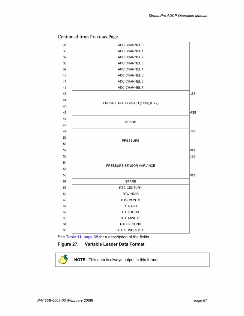
StreamPro ADCP Operation Manual
P/N 95B-6003-00 (February 2008) page 67
Continued from Previous Page 35 ADC CHANNEL 0
36 ADC CHANNEL 1
37 ADC CHANNEL 2
38 ADC CHANNEL 3
39 ADC CHANNEL 4
40 ADC CHANNEL 5
41 ADC CHANNEL 6
42 ADC CHANNEL 7
43 LSB
44
45
46
ERROR STATUS WORD (ESW) {CY?}
MSB
47
48 SPARE
49 LSB
50
51
52
PRESSURE
MSB
53 LSB
54
55
56
PRESSURE SENSOR VARIANCE
MSB
57 SPARE
58 RTC CENTURY
59 RTC YEAR
60 RTC MONTH
61 RTC DAY
62 RTC HOUR
63 RTC MINUTE
64 RTC SECOND
65 RTC HUNDREDTH
See Table 11, page 68 for a description of the fields.
Figure 27. Variable Leader Data Format
NOTE. This data is always output in this format.
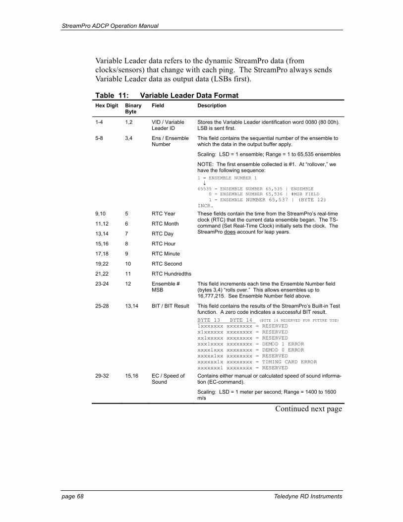
StreamPro ADCP Operation Manual
page 68 Teledyne RD Instruments
Variable Leader data refers to the dynamic StreamPro data (from clocks/sensors) that change with each ping. The StreamPro always sends Variable Leader data as output data (LSBs first).
Table 11: Variable Leader Data Format Hex Digit Binary
Byte Field Description
1-4 1,2 VID / Variable Leader ID
Stores the Variable Leader identification word 0080 (80 00h). LSB is sent first.
5-8 3,4 Ens / Ensemble Number
This field contains the sequential number of the ensemble to which the data in the output buffer apply.
Scaling: LSD = 1 ensemble; Range = 1 to 65,535 ensembles
NOTE: The first ensemble collected is #1. At “rollover,” we have the following sequence: 1 = ENSEMBLE NUMBER 1 ↓ 65535 = ENSEMBLE NUMBER 65,535 | ENSEMBLE 0 = ENSEMBLE NUMBER 65,536 | #MSB FIELD 1 = ENSEMBLE NUMBER 65,537 | (BYTE 12) INCR.
9,10
11,12
13,14
15,16
17,18
19,22
21,22
5
6
7
8
9
10
11
RTC Year
RTC Month
RTC Day
RTC Hour
RTC Minute
RTC Second
RTC Hundredths
These fields contain the time from the StreamPro’s real-time clock (RTC) that the current data ensemble began. The TS-command (Set Real-Time Clock) initially sets the clock. The StreamPro does account for leap years.
23-24 12 Ensemble # MSB
This field increments each time the Ensemble Number field (bytes 3,4) “rolls over.” This allows ensembles up to 16,777,215. See Ensemble Number field above.
25-28 13,14 BIT / BIT Result This field contains the results of the StreamPro’s Built-in Test function. A zero code indicates a successful BIT result. BYTE 13 BYTE 14 (BYTE 14 RESERVED FOR FUTURE USE) 1xxxxxxx xxxxxxxx = RESERVED x1xxxxxx xxxxxxxx = RESERVED xx1xxxxx xxxxxxxx = RESERVED xxx1xxxx xxxxxxxx = DEMOD 1 ERROR xxxx1xxx xxxxxxxx = DEMOD 0 ERROR xxxxx1xx xxxxxxxx = RESERVED xxxxxx1x xxxxxxxx = TIMING CARD ERROR xxxxxxx1 xxxxxxxx = RESERVED
29-32 15,16 EC / Speed of Sound
Contains either manual or calculated speed of sound informa-tion (EC-command).
Scaling: LSD = 1 meter per second; Range = 1400 to 1600 m/s
Continued next page
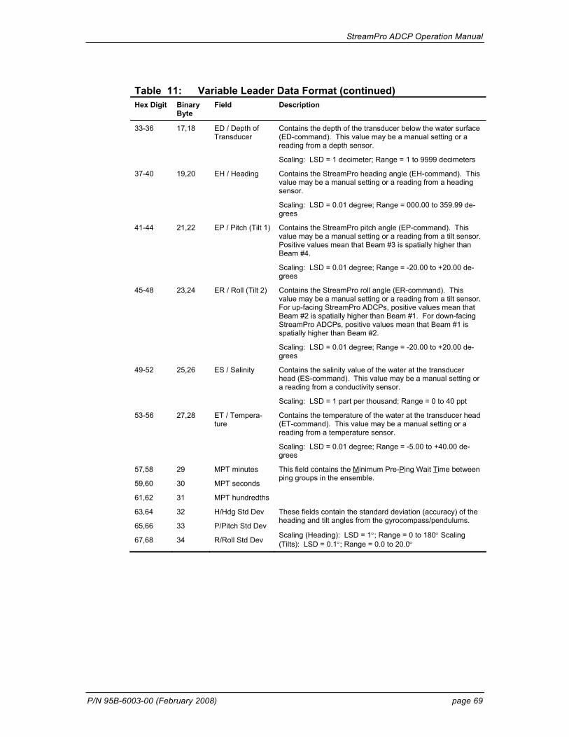
StreamPro ADCP Operation Manual
P/N 95B-6003-00 (February 2008) page 69
Table 11: Variable Leader Data Format (continued) Hex Digit Binary
Byte Field Description
33-36 17,18 ED / Depth of Transducer
Contains the depth of the transducer below the water surface (ED-command). This value may be a manual setting or a reading from a depth sensor.
Scaling: LSD = 1 decimeter; Range = 1 to 9999 decimeters
37-40 19,20 EH / Heading Contains the StreamPro heading angle (EH-command). This value may be a manual setting or a reading from a heading sensor.
Scaling: LSD = 0.01 degree; Range = 000.00 to 359.99 de-grees
41-44 21,22 EP / Pitch (Tilt 1) Contains the StreamPro pitch angle (EP-command). This value may be a manual setting or a reading from a tilt sensor. Positive values mean that Beam #3 is spatially higher than Beam #4.
Scaling: LSD = 0.01 degree; Range = -20.00 to +20.00 de-grees
45-48 23,24 ER / Roll (Tilt 2) Contains the StreamPro roll angle (ER-command). This value may be a manual setting or a reading from a tilt sensor. For up-facing StreamPro ADCPs, positive values mean that Beam #2 is spatially higher than Beam #1. For down-facing StreamPro ADCPs, positive values mean that Beam #1 is spatially higher than Beam #2.
Scaling: LSD = 0.01 degree; Range = -20.00 to +20.00 de-grees
49-52 25,26 ES / Salinity Contains the salinity value of the water at the transducer head (ES-command). This value may be a manual setting or a reading from a conductivity sensor.
Scaling: LSD = 1 part per thousand; Range = 0 to 40 ppt
53-56 27,28 ET / Tempera-ture
Contains the temperature of the water at the transducer head (ET-command). This value may be a manual setting or a reading from a temperature sensor.
Scaling: LSD = 0.01 degree; Range = -5.00 to +40.00 de-grees
57,58
59,60
61,62
29
30
31
MPT minutes
MPT seconds
MPT hundredths
This field contains the Minimum Pre-Ping Wait Time between ping groups in the ensemble.
63,64
65,66
67,68
32
33
34
H/Hdg Std Dev
P/Pitch Std Dev
R/Roll Std Dev
These fields contain the standard deviation (accuracy) of the heading and tilt angles from the gyrocompass/pendulums.
Scaling (Heading): LSD = 1°; Range = 0 to 180° Scaling (Tilts): LSD = 0.1°; Range = 0.0 to 20.0°
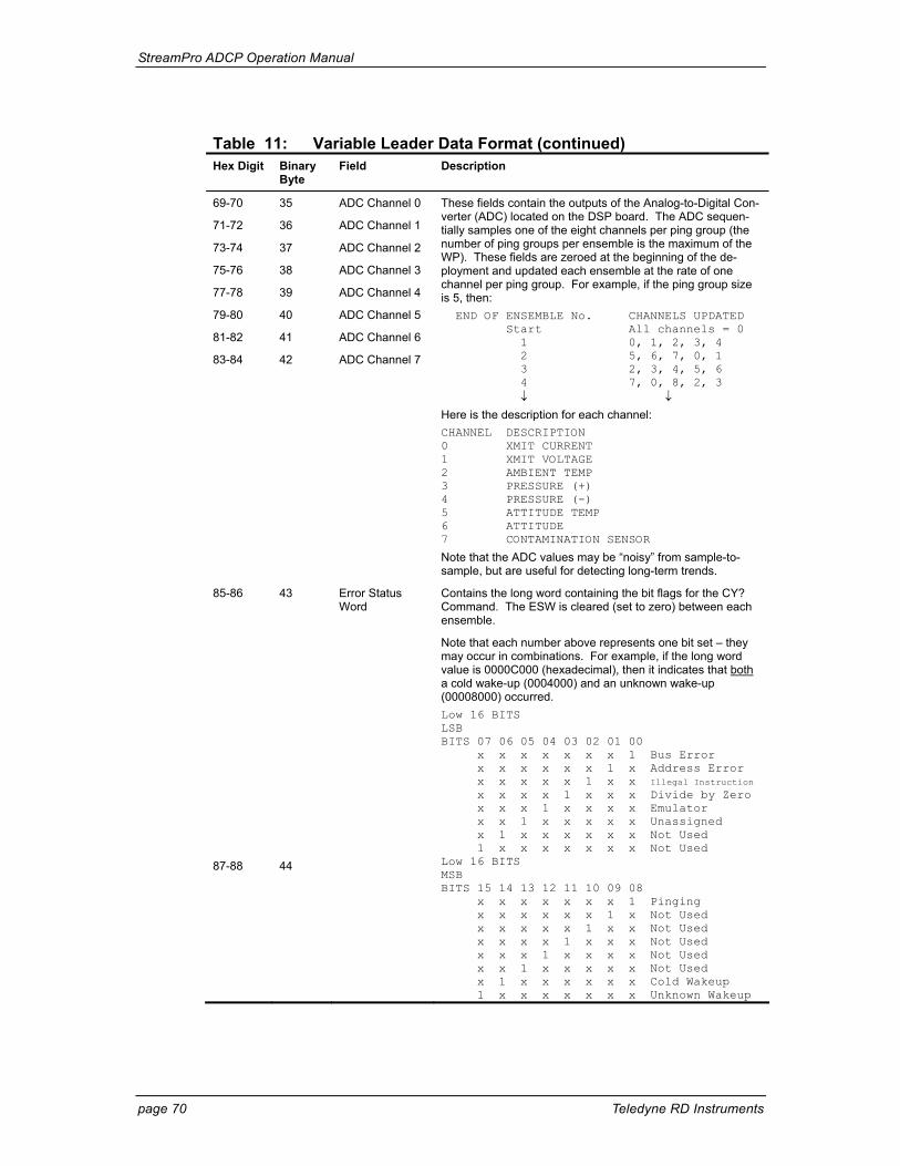
StreamPro ADCP Operation Manual
page 70 Teledyne RD Instruments
Table 11: Variable Leader Data Format (continued) Hex Digit Binary
Byte Field Description
69-70
71-72
73-74
75-76
77-78
79-80
81-82
83-84
35
36
37
38
39
40
41
42
ADC Channel 0
ADC Channel 1
ADC Channel 2
ADC Channel 3
ADC Channel 4
ADC Channel 5
ADC Channel 6
ADC Channel 7
These fields contain the outputs of the Analog-to-Digital Con-verter (ADC) located on the DSP board. The ADC sequen-tially samples one of the eight channels per ping group (the number of ping groups per ensemble is the maximum of the WP). These fields are zeroed at the beginning of the de-ployment and updated each ensemble at the rate of one channel per ping group. For example, if the ping group size is 5, then: END OF ENSEMBLE No. CHANNELS UPDATED Start All channels = 0 1 0, 1, 2, 3, 4 2 5, 6, 7, 0, 1 3 2, 3, 4, 5, 6 4 7, 0, 8, 2, 3 ↓ ↓ Here is the description for each channel: CHANNEL DESCRIPTION 0 XMIT CURRENT 1 XMIT VOLTAGE 2 AMBIENT TEMP 3 PRESSURE (+) 4 PRESSURE (-) 5 ATTITUDE TEMP 6 ATTITUDE 7 CONTAMINATION SENSOR
Note that the ADC values may be “noisy” from sample-to-sample, but are useful for detecting long-term trends.
85-86 43 Error Status Word
Contains the long word containing the bit flags for the CY? Command. The ESW is cleared (set to zero) between each ensemble.
Note that each number above represents one bit set – they may occur in combinations. For example, if the long word value is 0000C000 (hexadecimal), then it indicates that both a cold wake-up (0004000) and an unknown wake-up (00008000) occurred. Low 16 BITS LSB BITS 07 06 05 04 03 02 01 00 x x x x x x x 1 Bus Error x x x x x x 1 x Address Error x x x x x 1 x x Illegal Instruction x x x x 1 x x x Divide by Zero x x x 1 x x x x Emulator x x 1 x x x x x Unassigned x 1 x x x x x x Not Used 1 x x x x x x x Not Used
87-88 44 Low 16 BITS MSB BITS 15 14 13 12 11 10 09 08 x x x x x x x 1 Pinging x x x x x x 1 x Not Used x x x x x 1 x x Not Used x x x x 1 x x x Not Used x x x 1 x x x x Not Used x x 1 x x x x x Not Used x 1 x x x x x x Cold Wakeup 1 x x x x x x x Unknown Wakeup
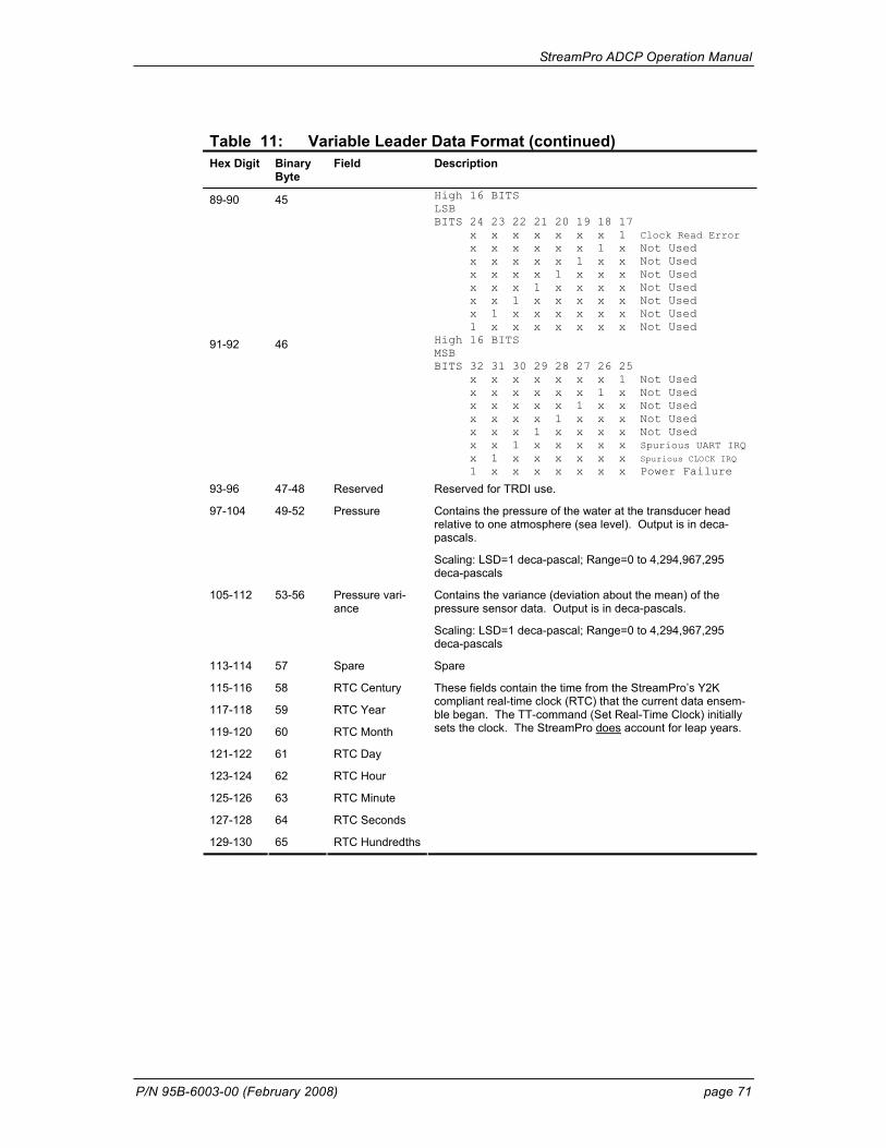
StreamPro ADCP Operation Manual
P/N 95B-6003-00 (February 2008) page 71
Table 11: Variable Leader Data Format (continued) Hex Digit Binary
Byte Field Description
89-90 45 High 16 BITS LSB BITS 24 23 22 21 20 19 18 17 x x x x x x x 1 Clock Read Error x x x x x x 1 x Not Used x x x x x 1 x x Not Used x x x x 1 x x x Not Used x x x 1 x x x x Not Used x x 1 x x x x x Not Used x 1 x x x x x x Not Used 1 x x x x x x x Not Used
91-92 46 High 16 BITS MSB BITS 32 31 30 29 28 27 26 25 x x x x x x x 1 Not Used x x x x x x 1 x Not Used x x x x x 1 x x Not Used x x x x 1 x x x Not Used x x x 1 x x x x Not Used x x 1 x x x x x Spurious UART IRQ x 1 x x x x x x Spurious CLOCK IRQ 1 x x x x x x x Power Failure
93-96 47-48 Reserved Reserved for TRDI use.
97-104 49-52 Pressure Contains the pressure of the water at the transducer head relative to one atmosphere (sea level). Output is in deca-pascals.
Scaling: LSD=1 deca-pascal; Range=0 to 4,294,967,295 deca-pascals
105-112 53-56 Pressure vari-ance
Contains the variance (deviation about the mean) of the pressure sensor data. Output is in deca-pascals.
Scaling: LSD=1 deca-pascal; Range=0 to 4,294,967,295 deca-pascals
113-114 57 Spare Spare
115-116 58 RTC Century
117-118 59 RTC Year
119-120 60 RTC Month
121-122 61 RTC Day
123-124 62 RTC Hour
125-126 63 RTC Minute
127-128 64 RTC Seconds
129-130 65 RTC Hundredths
These fields contain the time from the StreamPro’s Y2K compliant real-time clock (RTC) that the current data ensem-ble began. The TT-command (Set Real-Time Clock) initially sets the clock. The StreamPro does account for leap years.
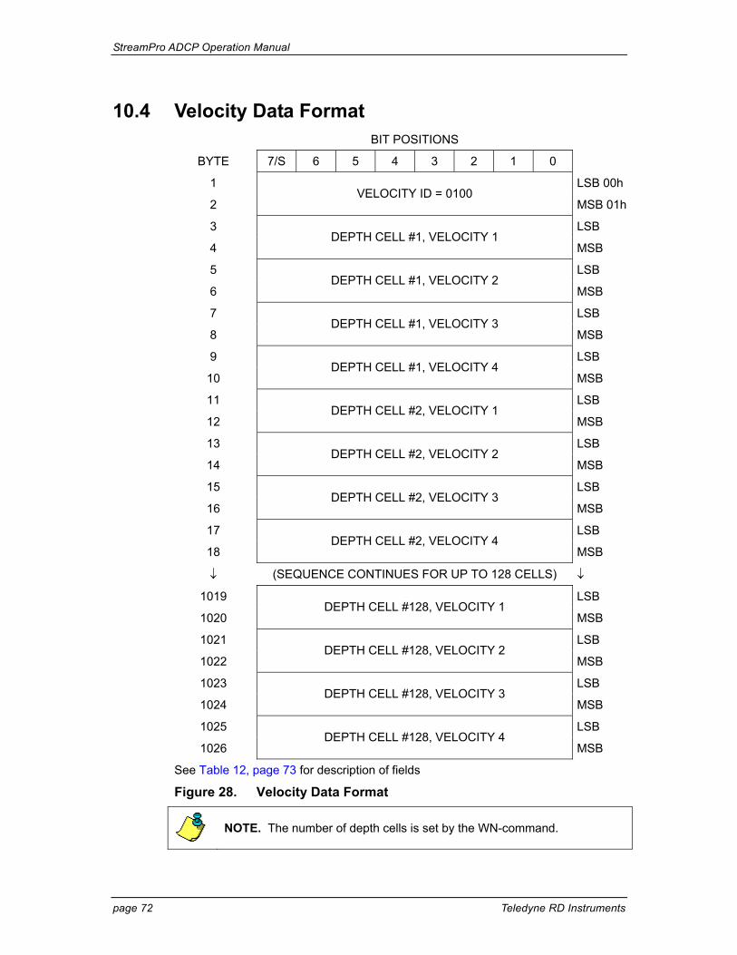
StreamPro ADCP Operation Manual
page 72 Teledyne RD Instruments
10.4 Velocity Data Format BIT POSITIONS
BYTE 7/S 6 5 4 3 2 1 0
1 LSB 00h
2 VELOCITY ID = 0100
MSB 01h
3 LSB
4 DEPTH CELL #1, VELOCITY 1
MSB
5 LSB
6 DEPTH CELL #1, VELOCITY 2
MSB
7 LSB
8 DEPTH CELL #1, VELOCITY 3
MSB
9 LSB
10 DEPTH CELL #1, VELOCITY 4
MSB
11 LSB
12 DEPTH CELL #2, VELOCITY 1
MSB
13 LSB
14 DEPTH CELL #2, VELOCITY 2
MSB
15 LSB
16 DEPTH CELL #2, VELOCITY 3
MSB
17 LSB
18 DEPTH CELL #2, VELOCITY 4
MSB
↓ (SEQUENCE CONTINUES FOR UP TO 128 CELLS) ↓
1019 LSB
1020 DEPTH CELL #128, VELOCITY 1
MSB
1021 LSB
1022 DEPTH CELL #128, VELOCITY 2
MSB
1023 LSB
1024 DEPTH CELL #128, VELOCITY 3
MSB
1025 LSB
1026 DEPTH CELL #128, VELOCITY 4
MSB
See Table 12, page 73 for description of fields
Figure 28. Velocity Data Format
NOTE. The number of depth cells is set by the WN-command.
StreamPro ADCP Operation Manual
P/N 95B-6003-00 (February 2008) page 73
The StreamPro packs velocity data for each depth cell of each beam into a two-byte, two’s-complement integer [-32768, 32767] with the LSB sent first. The StreamPro scales velocity data in millimeters per second (mm/s). A value of –32768 (8000h) indicates bad velocity values.
All velocities are relative based on a stationary instrument. To obtain abso-lute velocities, algebraically remove the velocity of the instrument. For ex-ample, RELATIVE WATER CURRENT VELOCITY: EAST 650 mm/s INSTRUMENT VELOCITY : (-) EAST 600 mm/s ABSOLUTE WATER VELOCITY : EAST 50 mm/s
The setting of the EX-command (Coordinate Transformation) determines how the StreamPro references the velocity data as shown below.
EX-CMD COORD SYS VEL 1 VEL 2 VEL 3 VEL 4
xxx00xxx BEAM TO BEAM 1 TO BEAM 2 TO BEAM 3 TO BEAM 4
xxx01xxx INST Bm1-Bm2 Bm4-Bm3 TO XDUCER ERR VEL
xxx10xxx SHIP PRT-STBD AFT-FWD TO SURFACE ERR VEL
xxx11xxx EARTH TO EAST TO NORTH TO SURFACE ERR VEL
POSITIVE VALUES INDICATE WATER MOVEMENT
Table 12: Velocity Data Format Hex Digit Binary
Byte Field Description
1-4 1,2 Velocity ID Stores the velocity data identification word 0100 (00 01h). LSB is sent first.
5-8 3,4 Depth Cell 1, Velocity 1
Stores velocity data for depth cell #1, velocity 1. See above.
9-12 5,6 Depth Cell 1, Velocity 2
Stores velocity data for depth cell #1, velocity 2. See above.
13-16 7,8 Depth Cell 1, Velocity 3
Stores velocity data for depth cell #1, velocity 3. See above.
17-20 9,10 Depth Cell 1, Velocity 4
Stores velocity data for depth cell #1, velocity 4. See above.
21-2052 11-1026 Cells 2 – 128 (if used)
These fields store the velocity data for depth cells 2 through 128 (depending on the setting of the WN-command). These fields follow the same format as listed above for depth cell 1.
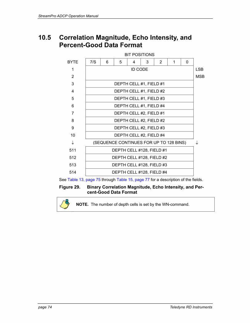
StreamPro ADCP Operation Manual
page 74 Teledyne RD Instruments
10.5 Correlation Magnitude, Echo Intensity, and Percent-Good Data Format
BIT POSITIONS
BYTE 7/S 6 5 4 3 2 1 0
1 ID CODE LSB
2 MSB
3 DEPTH CELL #1, FIELD #1
4 DEPTH CELL #1, FIELD #2
5 DEPTH CELL #1, FIELD #3
6 DEPTH CELL #1, FIELD #4
7 DEPTH CELL #2, FIELD #1
8 DEPTH CELL #2, FIELD #2
9 DEPTH CELL #2, FIELD #3
10 DEPTH CELL #2, FIELD #4
↓ (SEQUENCE CONTINUES FOR UP TO 128 BINS) ↓
511 DEPTH CELL #128, FIELD #1
512 DEPTH CELL #128, FIELD #2
513 DEPTH CELL #128, FIELD #3
514 DEPTH CELL #128, FIELD #4
See Table 13, page 75 through Table 15, page 77 for a description of the fields.
Figure 29. Binary Correlation Magnitude, Echo Intensity, and Per-cent-Good Data Format
NOTE. The number of depth cells is set by the WN-command.
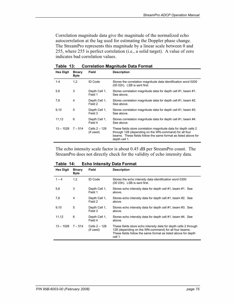
StreamPro ADCP Operation Manual
P/N 95B-6003-00 (February 2008) page 75
Correlation magnitude data give the magnitude of the normalized echo autocorrelation at the lag used for estimating the Doppler phase change. The StreamPro represents this magnitude by a linear scale between 0 and 255, where 255 is perfect correlation (i.e., a solid target). A value of zero indicates bad correlation values.
Table 13: Correlation Magnitude Data Format Hex Digit Binary
Byte Field Description
1-4 1,2 ID Code Stores the correlation magnitude data identification word 0200 (00 02h). LSB is sent first.
5,6 3 Depth Cell 1, Field 1
Stores correlation magnitude data for depth cell #1, beam #1. See above.
7,8 4 Depth Cell 1, Field 2
Stores correlation magnitude data for depth cell #1, beam #2. See above.
9,10 5 Depth Cell 1, Field 3
Stores correlation magnitude data for depth cell #1, beam #3. See above.
11,12 6 Depth Cell 1, Field 4
Stores correlation magnitude data for depth cell #1, beam #4. See above.
13 – 1028 7 – 514 Cells 2 – 128 (if used)
These fields store correlation magnitude data for depth cells 2 through 128 (depending on the WN-command) for all four beams. These fields follow the same format as listed above for depth cell 1.
The echo intensity scale factor is about 0.45 dB per StreamPro count. The StreamPro does not directly check for the validity of echo intensity data.
Table 14: Echo Intensity Data Format Hex Digit Binary
Byte Field Description
1 – 4 1,2 ID Code Stores the echo intensity data identification word 0300 (00 03h). LSB is sent first.
5,6 3 Depth Cell 1, Field 1
Stores echo intensity data for depth cell #1, beam #1. See above.
7,8 4 Depth Cell 1, Field 2
Stores echo intensity data for depth cell #1, beam #2. See above.
9,10 5 Depth Cell 1, Field 3
Stores echo intensity data for depth cell #1, beam #3. See above.
11,12 6 Depth Cell 1, Field 4
Stores echo intensity data for depth cell #1, beam #4. See above.
13 – 1028 7 – 514 Cells 2 – 128 (if used)
These fields store echo intensity data for depth cells 2 through 128 (depending on the WN-command) for all four beams. These fields follow the same format as listed above for depth cell 1.
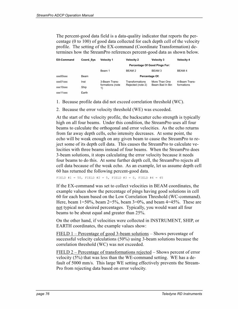
StreamPro ADCP Operation Manual
page 76 Teledyne RD Instruments
The percent-good data field is a data-quality indicator that reports the per-centage (0 to 100) of good data collected for each depth cell of the velocity profile. The setting of the EX-command (Coordinate Transformation) de-termines how the StreamPro references percent-good data as shown below.
Velocity 1 Velocity 2 Velocity 3 Velocity 4
Percentage Of Good Pings For:
EX-Command Coord. Sys
Beam 1 BEAM 2 BEAM 3 BEAM 4
xxx00xxx Beam Percentage Of:
xxx01xxx Inst
xxx10xxx Ship
xxx11xxx Earth
3-Beam Trans-formations (note 1)
Transformations Rejected (note 2)
More Than One Beam Bad In Bin
4-Beam Trans-formations
1. Because profile data did not exceed correlation threshold (WC).
2. Because the error velocity threshold (WE) was exceeded.
At the start of the velocity profile, the backscatter echo strength is typically high on all four beams. Under this condition, the StreamPro uses all four beams to calculate the orthogonal and error velocities. As the echo returns from far away depth cells, echo intensity decreases. At some point, the echo will be weak enough on any given beam to cause the StreamPro to re-ject some of its depth cell data. This causes the StreamPro to calculate ve-locities with three beams instead of four beams. When the StreamPro does 3-beam solutions, it stops calculating the error velocity because it needs four beams to do this. At some further depth cell, the StreamPro rejects all cell data because of the weak echo. As an example, let us assume depth cell 60 has returned the following percent-good data. FIELD #1 = 50, FIELD #2 = 5, FIELD #3 = 0, FIELD #4 = 45
If the EX-command was set to collect velocities in BEAM coordinates, the example values show the percentage of pings having good solutions in cell 60 for each beam based on the Low Correlation Threshold (WC-command). Here, beam 1=50%, beam 2=5%, beam 3=0%, and beam 4=45%. These are not typical nor desired percentages. Typically, you would want all four beams to be about equal and greater than 25%.
On the other hand, if velocities were collected in INSTRUMENT, SHIP, or EARTH coordinates, the example values show:
FIELD 1 – Percentage of good 3-beam solutions – Shows percentage of successful velocity calculations (50%) using 3-beam solutions because the correlation threshold (WC) was not exceeded.
FIELD 2 – Percentage of transformations rejected – Shows percent of error velocity (5%) that was less than the WE-command setting. WE has a de-fault of 5000 mm/s. This large WE setting effectively prevents the Stream-Pro from rejecting data based on error velocity.
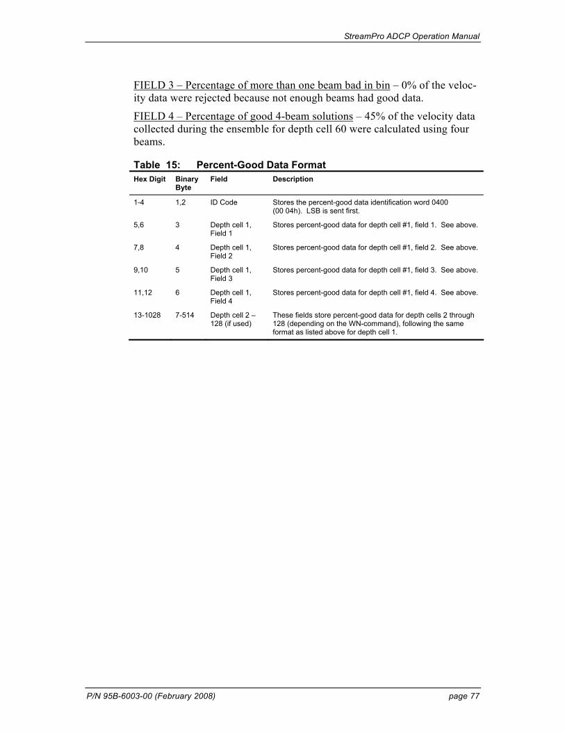
StreamPro ADCP Operation Manual
P/N 95B-6003-00 (February 2008) page 77
FIELD 3 – Percentage of more than one beam bad in bin – 0% of the veloc-ity data were rejected because not enough beams had good data.
FIELD 4 – Percentage of good 4-beam solutions – 45% of the velocity data collected during the ensemble for depth cell 60 were calculated using four beams.
Table 15: Percent-Good Data Format Hex Digit Binary
Byte Field Description
1-4 1,2 ID Code Stores the percent-good data identification word 0400 (00 04h). LSB is sent first.
5,6 3 Depth cell 1, Field 1
Stores percent-good data for depth cell #1, field 1. See above.
7,8 4 Depth cell 1, Field 2
Stores percent-good data for depth cell #1, field 2. See above.
9,10 5 Depth cell 1, Field 3
Stores percent-good data for depth cell #1, field 3. See above.
11,12 6 Depth cell 1, Field 4
Stores percent-good data for depth cell #1, field 4. See above.
13-1028 7-514 Depth cell 2 – 128 (if used)
These fields store percent-good data for depth cells 2 through 128 (depending on the WN-command), following the same format as listed above for depth cell 1.
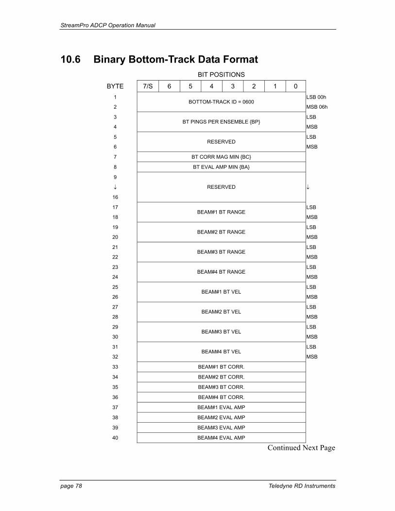
StreamPro ADCP Operation Manual
page 78 Teledyne RD Instruments
10.6 Binary Bottom-Track Data Format BIT POSITIONS
BYTE 7/S 6 5 4 3 2 1 0 1 LSB 00h
2 BOTTOM-TRACK ID = 0600
MSB 06h
3 LSB
4 BT PINGS PER ENSEMBLE {BP}
MSB
5 LSB
6 RESERVED
MSB
7 BT CORR MAG MIN {BC}
8 BT EVAL AMP MIN {BA}
9
↓ ↓
16
RESERVED
17 LSB
18 BEAM#1 BT RANGE
MSB
19 LSB
20 BEAM#2 BT RANGE
MSB
21 LSB
22 BEAM#3 BT RANGE
MSB
23 LSB
24 BEAM#4 BT RANGE
MSB
25 LSB
26 BEAM#1 BT VEL
MSB
27 LSB
28 BEAM#2 BT VEL
MSB
29 LSB
30 BEAM#3 BT VEL
MSB
31 LSB
32 BEAM#4 BT VEL
MSB
33 BEAM#1 BT CORR.
34 BEAM#2 BT CORR.
35 BEAM#3 BT CORR.
36 BEAM#4 BT CORR.
37 BEAM#1 EVAL AMP
38 BEAM#2 EVAL AMP
39 BEAM#3 EVAL AMP
40 BEAM#4 EVAL AMP
Continued Next Page
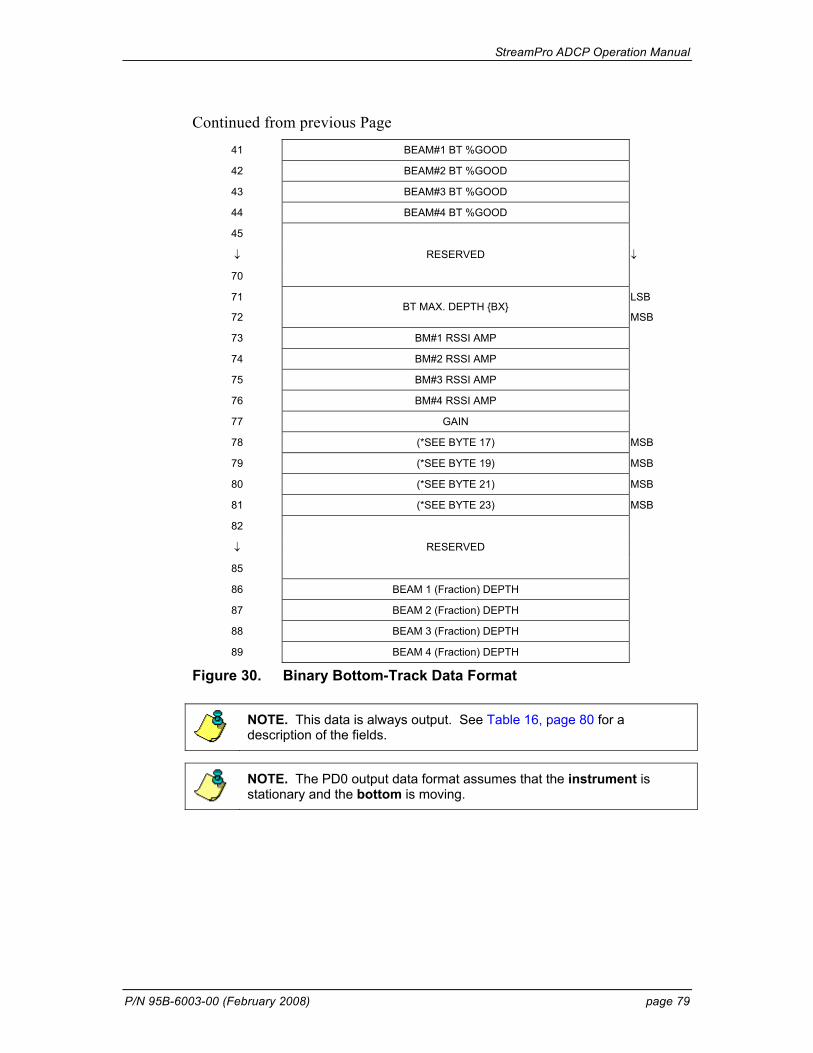
StreamPro ADCP Operation Manual
P/N 95B-6003-00 (February 2008) page 79
Continued from previous Page 41 BEAM#1 BT %GOOD
42 BEAM#2 BT %GOOD
43 BEAM#3 BT %GOOD
44 BEAM#4 BT %GOOD
45
↓ ↓
70
RESERVED
71 LSB
72 BT MAX. DEPTH {BX}
MSB
73 BM#1 RSSI AMP
74 BM#2 RSSI AMP
75 BM#3 RSSI AMP
76 BM#4 RSSI AMP
77 GAIN
78 (*SEE BYTE 17) MSB
79 (*SEE BYTE 19) MSB
80 (*SEE BYTE 21) MSB
81 (*SEE BYTE 23) MSB
82
↓
85
RESERVED
86 BEAM 1 (Fraction) DEPTH
87 BEAM 2 (Fraction) DEPTH
88 BEAM 3 (Fraction) DEPTH
89 BEAM 4 (Fraction) DEPTH
Figure 30. Binary Bottom-Track Data Format
NOTE. This data is always output. See Table 16, page 80 for a description of the fields.
NOTE. The PD0 output data format assumes that the instrument is stationary and the bottom is moving.
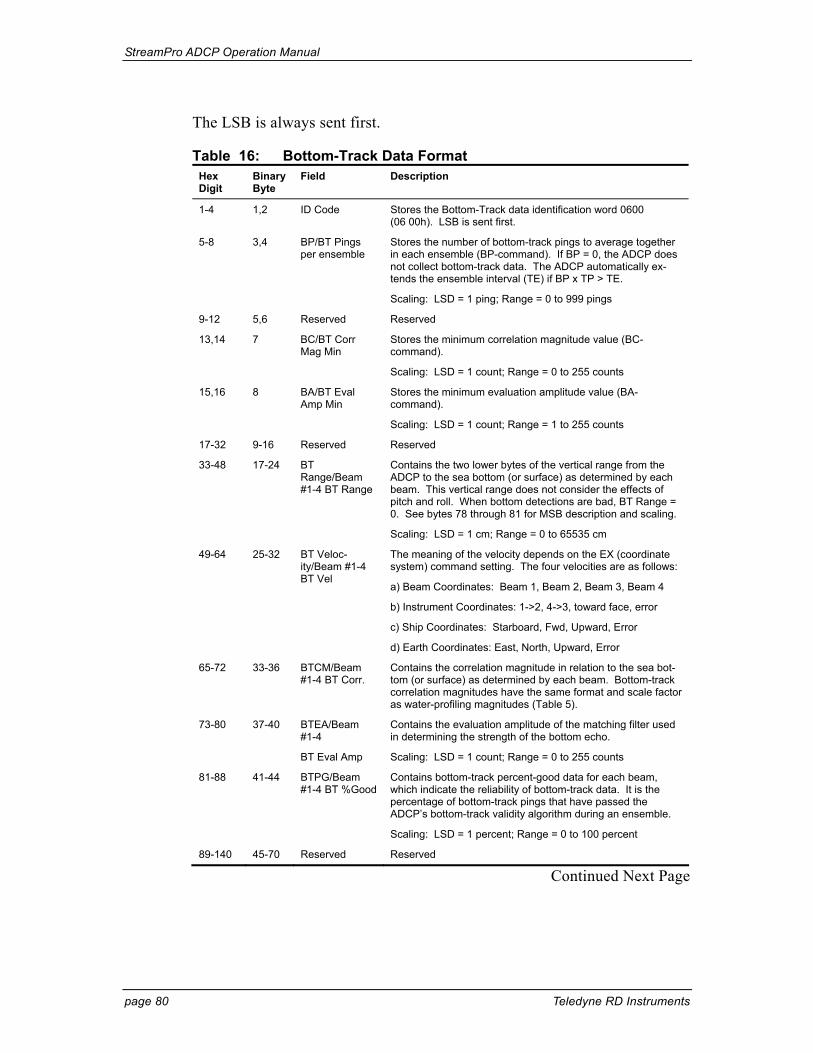
StreamPro ADCP Operation Manual
page 80 Teledyne RD Instruments
The LSB is always sent first.
Table 16: Bottom-Track Data Format Hex Digit
Binary Byte
Field Description
1-4 1,2 ID Code Stores the Bottom-Track data identification word 0600 (06 00h). LSB is sent first.
5-8 3,4 BP/BT Pings per ensemble
Stores the number of bottom-track pings to average together in each ensemble (BP-command). If BP = 0, the ADCP does not collect bottom-track data. The ADCP automatically ex-tends the ensemble interval (TE) if BP x TP > TE.
Scaling: LSD = 1 ping; Range = 0 to 999 pings
9-12 5,6 Reserved Reserved
13,14 7 BC/BT Corr Mag Min
Stores the minimum correlation magnitude value (BC-command).
Scaling: LSD = 1 count; Range = 0 to 255 counts
15,16 8 BA/BT Eval Amp Min
Stores the minimum evaluation amplitude value (BA-command).
Scaling: LSD = 1 count; Range = 1 to 255 counts
17-32 9-16 Reserved Reserved
33-48 17-24 BT Range/Beam #1-4 BT Range
Contains the two lower bytes of the vertical range from the ADCP to the sea bottom (or surface) as determined by each beam. This vertical range does not consider the effects of pitch and roll. When bottom detections are bad, BT Range = 0. See bytes 78 through 81 for MSB description and scaling.
Scaling: LSD = 1 cm; Range = 0 to 65535 cm
49-64 25-32 BT Veloc-ity/Beam #1-4 BT Vel
The meaning of the velocity depends on the EX (coordinate system) command setting. The four velocities are as follows:
a) Beam Coordinates: Beam 1, Beam 2, Beam 3, Beam 4
b) Instrument Coordinates: 1->2, 4->3, toward face, error
c) Ship Coordinates: Starboard, Fwd, Upward, Error
d) Earth Coordinates: East, North, Upward, Error
65-72 33-36 BTCM/Beam #1-4 BT Corr.
Contains the correlation magnitude in relation to the sea bot-tom (or surface) as determined by each beam. Bottom-track correlation magnitudes have the same format and scale factor as water-profiling magnitudes (Table 5).
73-80 37-40 BTEA/Beam #1-4
BT Eval Amp
Contains the evaluation amplitude of the matching filter used in determining the strength of the bottom echo.
Scaling: LSD = 1 count; Range = 0 to 255 counts
81-88 41-44 BTPG/Beam #1-4 BT %Good
Contains bottom-track percent-good data for each beam, which indicate the reliability of bottom-track data. It is the percentage of bottom-track pings that have passed the ADCP’s bottom-track validity algorithm during an ensemble.
Scaling: LSD = 1 percent; Range = 0 to 100 percent
89-140 45-70 Reserved Reserved
Continued Next Page
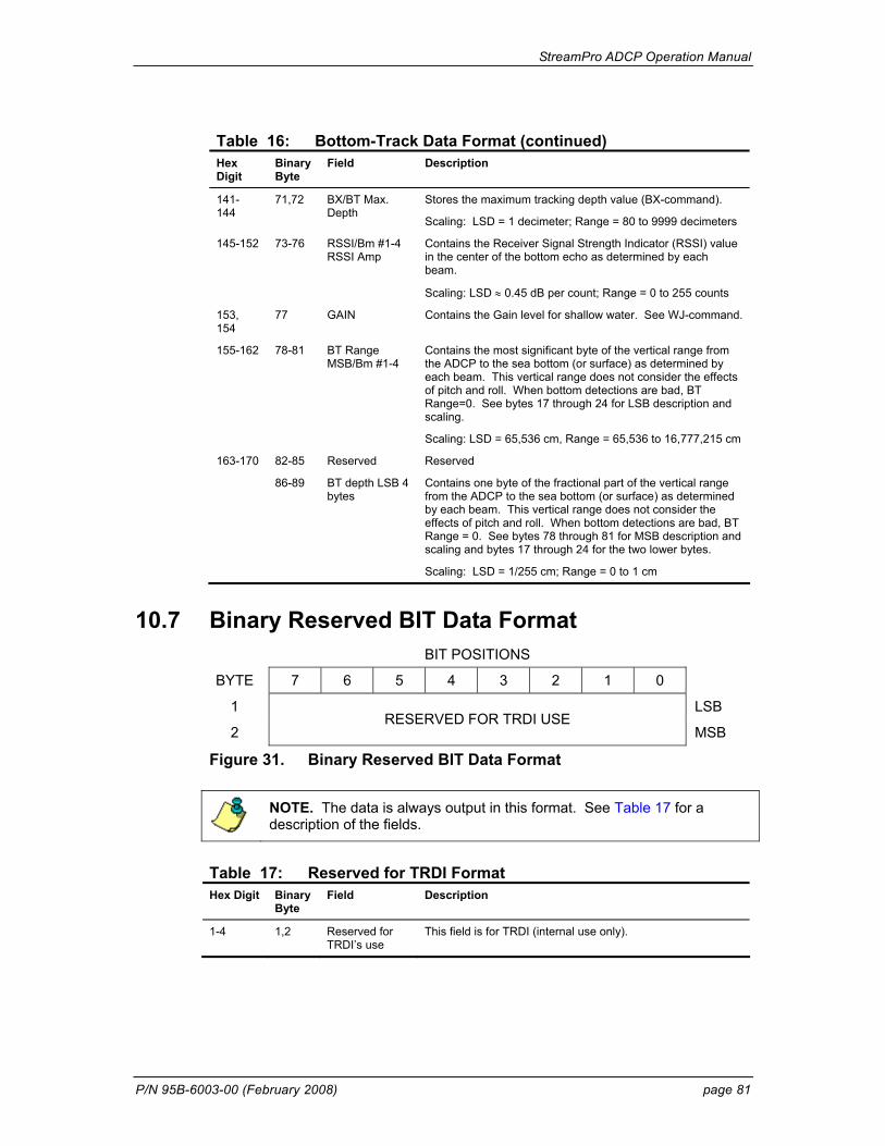
StreamPro ADCP Operation Manual
P/N 95B-6003-00 (February 2008) page 81
Table 16: Bottom-Track Data Format (continued) Hex Digit
Binary Byte
Field Description
141- 144
71,72 BX/BT Max. Depth
Stores the maximum tracking depth value (BX-command).
Scaling: LSD = 1 decimeter; Range = 80 to 9999 decimeters
145-152 73-76 RSSI/Bm #1-4 RSSI Amp
Contains the Receiver Signal Strength Indicator (RSSI) value in the center of the bottom echo as determined by each beam.
Scaling: LSD ≈ 0.45 dB per count; Range = 0 to 255 counts
153, 154
77 GAIN Contains the Gain level for shallow water. See WJ-command.
155-162 78-81 BT Range MSB/Bm #1-4
Contains the most significant byte of the vertical range from the ADCP to the sea bottom (or surface) as determined by each beam. This vertical range does not consider the effects of pitch and roll. When bottom detections are bad, BT Range=0. See bytes 17 through 24 for LSB description and scaling.
Scaling: LSD = 65,536 cm, Range = 65,536 to 16,777,215 cm
163-170 82-85 Reserved Reserved
86-89 BT depth LSB 4 bytes
Contains one byte of the fractional part of the vertical range from the ADCP to the sea bottom (or surface) as determined by each beam. This vertical range does not consider the effects of pitch and roll. When bottom detections are bad, BT Range = 0. See bytes 78 through 81 for MSB description and scaling and bytes 17 through 24 for the two lower bytes.
Scaling: LSD = 1/255 cm; Range = 0 to 1 cm
10.7 Binary Reserved BIT Data Format BIT POSITIONS
BYTE 7 6 5 4 3 2 1 0
1 LSB
2 RESERVED FOR TRDI USE
MSB
Figure 31. Binary Reserved BIT Data Format
NOTE. The data is always output in this format. See Table 17 for a description of the fields.
Table 17: Reserved for TRDI Format Hex Digit Binary
Byte Field Description
1-4 1,2 Reserved for TRDI’s use
This field is for TRDI (internal use only).

StreamPro ADCP Operation Manual
page 82 Teledyne RD Instruments
10.8 Binary Checksum Data Format BIT POSITIONS
BYTE 7 6 5 4 3 2 1 0
1 LSB
2 CHECKSUM DATA
MSB
Figure 32. Binary Checksum Data Format
NOTE. The data is always output in this format. See Table 18 for a description of the fields.
Table 18: Checksum Data Format Hex Digit Binary
Byte Field Description
1-4 1,2 Checksum Data This field contains a modulo 65535 checksum. The Stream-Pro computes the checksum by summing all the bytes in the output buffer excluding the checksum.
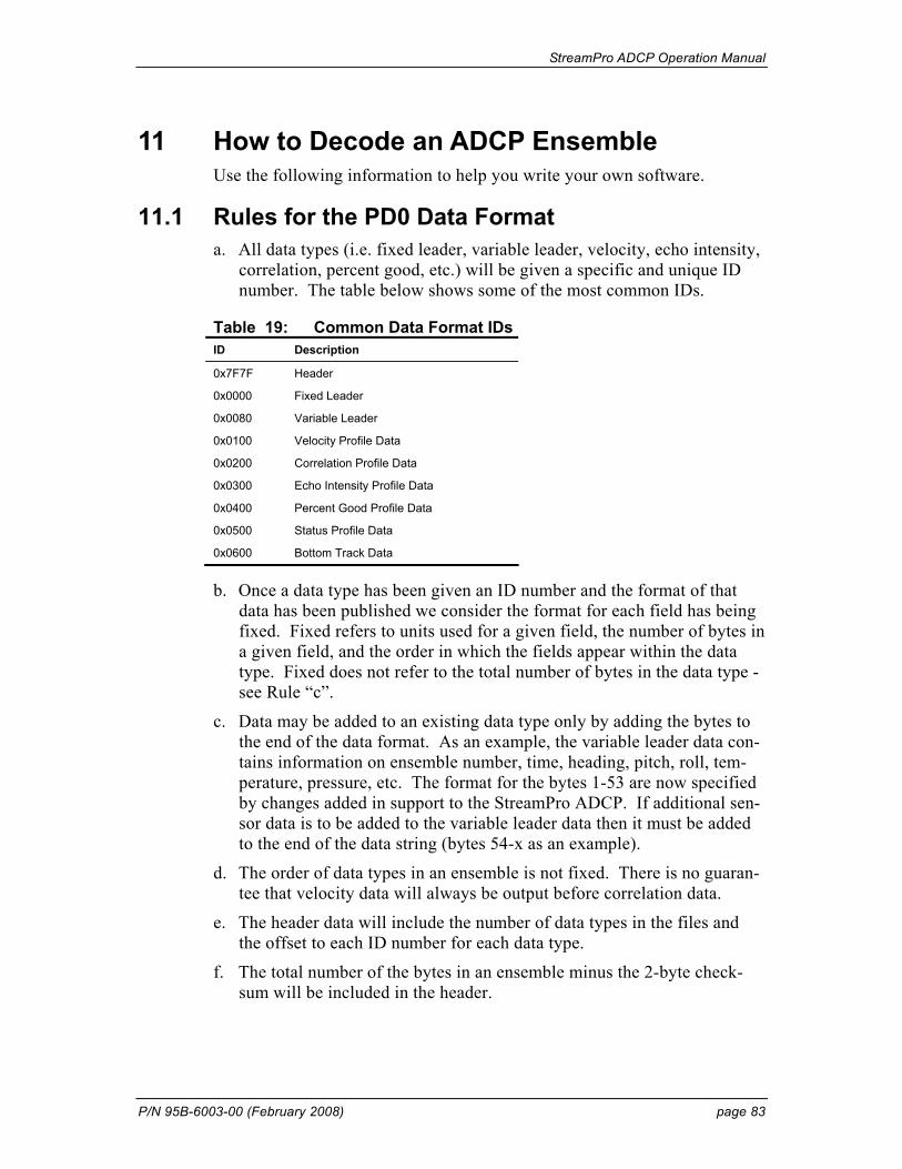
StreamPro ADCP Operation Manual
P/N 95B-6003-00 (February 2008) page 83
11 How to Decode an ADCP Ensemble Use the following information to help you write your own software.
11.1 Rules for the PD0 Data Format a. All data types (i.e. fixed leader, variable leader, velocity, echo intensity,
correlation, percent good, etc.) will be given a specific and unique ID number. The table below shows some of the most common IDs.
Table 19: Common Data Format IDs ID Description
0x7F7F Header
0x0000 Fixed Leader
0x0080 Variable Leader
0x0100 Velocity Profile Data
0x0200 Correlation Profile Data
0x0300 Echo Intensity Profile Data
0x0400 Percent Good Profile Data
0x0500 Status Profile Data
0x0600 Bottom Track Data
b. Once a data type has been given an ID number and the format of that data has been published we consider the format for each field has being fixed. Fixed refers to units used for a given field, the number of bytes in a given field, and the order in which the fields appear within the data type. Fixed does not refer to the total number of bytes in the data type - see Rule “c”.
c. Data may be added to an existing data type only by adding the bytes to the end of the data format. As an example, the variable leader data con-tains information on ensemble number, time, heading, pitch, roll, tem-perature, pressure, etc. The format for the bytes 1-53 are now specified by changes added in support to the StreamPro ADCP. If additional sen-sor data is to be added to the variable leader data then it must be added to the end of the data string (bytes 54-x as an example).
d. The order of data types in an ensemble is not fixed. There is no guaran-tee that velocity data will always be output before correlation data.
e. The header data will include the number of data types in the files and the offset to each ID number for each data type.
f. The total number of the bytes in an ensemble minus the 2-byte check-sum will be included in the header.
StreamPro ADCP Operation Manual
page 84 Teledyne RD Instruments
11.2 Recommended Data Decoding Sequence for PD0 Data Format a. Locate the header data by locating the header ID number (in the case of
PD0 profile data that will be 7F7F).
b. Confirm that you have the correct header ID by:
1. Locating the total number of bytes (located in the header data) in the ensemble. This will be your offset to the next ensemble.
2. Calculate the checksum of total number of bytes in the ensemble ex-cluding the checksum. The checksum is calculated by adding the value of each byte. The 2-byte least significant digits that you calcu-late will be the checksum.
3. Read the 2-byte checksum word at the end of the ensemble, located by using the checksum offset in the header (determined in step “b-1”) and compare this checksum word to the value calculated in step “b-2”.
4. If the checksums match then you have a valid ensemble. If the checksums do not match then you do not have a valid ensemble and you need to go back to step “a” and search for the next header ID number occurrence.
c. Locate the number of data types (located in the header data).
d. Locate the offset to each data type (located in the header data).
e. Locate the data ID type you wish to decode by using the offset to each data type and confirm the data ID number at that offset matches the ID type you are looking for.
f. Once the proper ID type has been located, use the ADCP Technical Manual for the ADCP you are using to understand what each byte repre-sents in that particular data type.
11.3 Pseudo-Code for Decoding PD0 Ensemble Data The following examples show the pseudo-code for decoding PD0 and PD5 ensemble data.
g. Define structures, which contain all fields in all data types of the PD0 format.
1. typedef struct { <lists of types and fields> } FixedLeader.
2. typedef struct { <lists of types and fields> } VariableLeader.
3. typedef struct { <lists of types and fields> } BottomTrack.
4. typedef struct { <lists of types and fields> } VelocityType
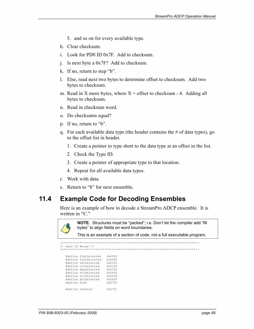
StreamPro ADCP Operation Manual
P/N 95B-6003-00 (February 2008) page 85
5. and so on for every available type.
h. Clear checksum.
i. Look for PD0 ID 0x7F. Add to checksum.
j. Is next byte a 0x7F? Add to checksum.
k. If no, return to step “b”.
l. Else, read next two bytes to determine offset to checksum. Add two bytes to checksum.
m. Read in X more bytes, where X = offset to checksum - 4. Adding all bytes to checksum.
n. Read in checksum word.
o. Do checksums equal?
p. If no, return to “b”.
q. For each available data type (the header contains the # of data types), go to the offset list in header.
1. Create a pointer to type short to the data type at an offset in the list.
2. Check the Type ID.
3. Create a pointer of appropriate type to that location.
4. Repeat for all available data types.
r. Work with data.
s. Return to “b” for next ensemble.
11.4 Example Code for Decoding Ensembles Here is an example of how to decode a StreamPro ADCP ensemble. It is written in “C.”
NOTE. Structures must be “packed”; i.e. Don’t let the compiler add “fill bytes” to align fields on word boundaries.
This is an example of a section of code, not a full executable program. /****************************************************************************/ /* Data ID Words */ /****************************************************************************/ #define FLdrSelected 0x0000 #define VLdrSelected 0x0080 #define VelSelected 0x0100 #define CorSelected 0x0200 #define AmpSelected 0x0300 #define PctSelected 0x0400 #define SttSelected 0x0500 #define BotSelected 0x0600 #define Prm0 0x0700 #define VelGood 0x0701
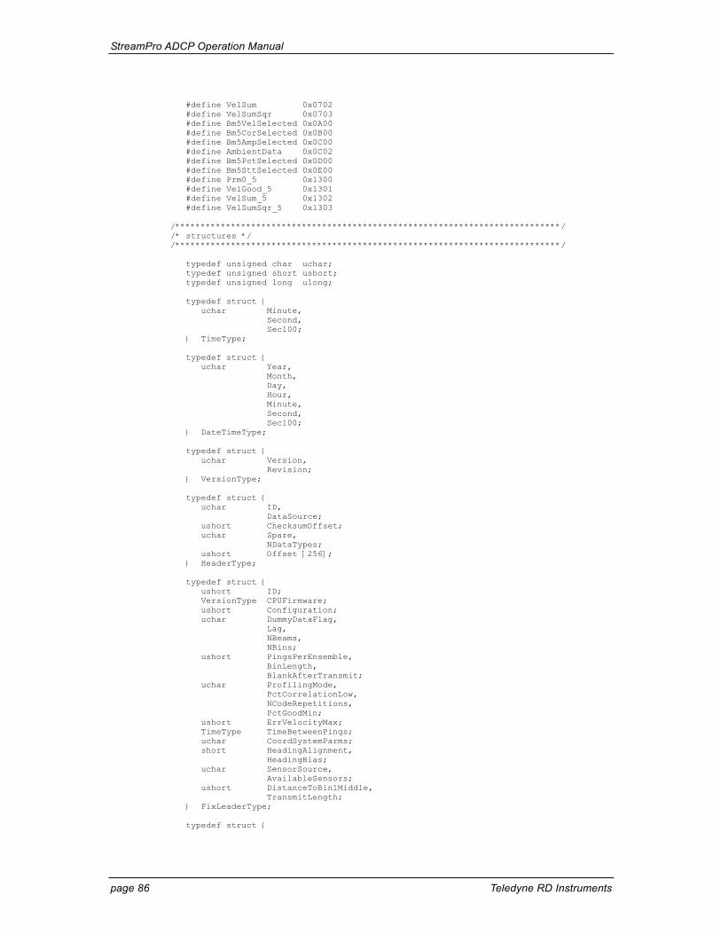
StreamPro ADCP Operation Manual
page 86 Teledyne RD Instruments
#define VelSum 0x0702 #define VelSumSqr 0x0703 #define Bm5VelSelected 0x0A00 #define Bm5CorSelected 0x0B00 #define Bm5AmpSelected 0x0C00 #define AmbientData 0x0C02 #define Bm5PctSelected 0x0D00 #define Bm5SttSelected 0x0E00 #define Prm0_5 0x1300 #define VelGood_5 0x1301 #define VelSum_5 0x1302 #define VelSumSqr_5 0x1303 /****************************************************************************/ /* structures */ /****************************************************************************/ typedef unsigned char uchar; typedef unsigned short ushort; typedef unsigned long ulong; typedef struct { uchar Minute, Second, Sec100; } TimeType; typedef struct { uchar Year, Month, Day, Hour, Minute, Second, Sec100; } DateTimeType; typedef struct { uchar Version, Revision; } VersionType; typedef struct { uchar ID, DataSource; ushort ChecksumOffset; uchar Spare, NDataTypes; ushort Offset [256]; } HeaderType; typedef struct { ushort ID; VersionType CPUFirmware; ushort Configuration; uchar DummyDataFlag, Lag, NBeams, NBins; ushort PingsPerEnsemble, BinLength, BlankAfterTransmit; uchar ProfilingMode, PctCorrelationLow, NCodeRepetitions, PctGoodMin; ushort ErrVelocityMax; TimeType TimeBetweenPings; uchar CoordSystemParms; short HeadingAlignment, HeadingBias; uchar SensorSource, AvailableSensors; ushort DistanceToBin1Middle, TransmitLength; } FixLeaderType; typedef struct {
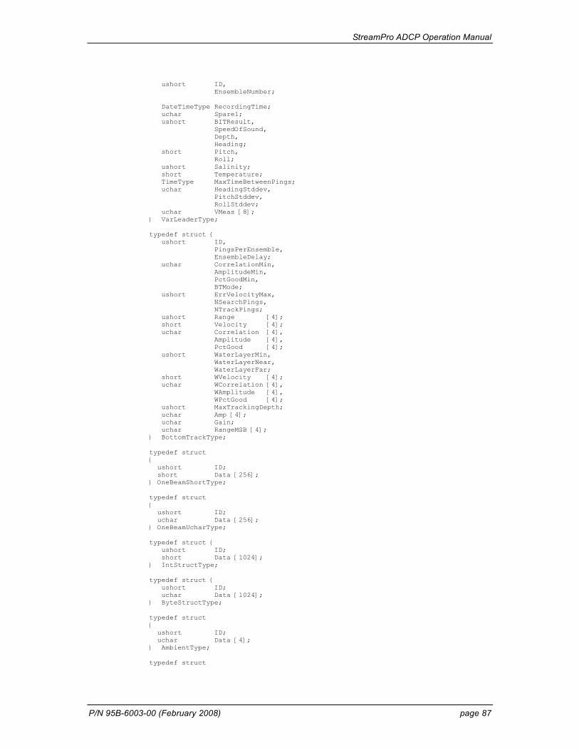
StreamPro ADCP Operation Manual
P/N 95B-6003-00 (February 2008) page 87
ushort ID, EnsembleNumber; DateTimeType RecordingTime; uchar Spare1; ushort BITResult, SpeedOfSound, Depth, Heading; short Pitch, Roll; ushort Salinity; short Temperature; TimeType MaxTimeBetweenPings; uchar HeadingStddev, PitchStddev, RollStddev; uchar VMeas [8]; } VarLeaderType; typedef struct { ushort ID, PingsPerEnsemble, EnsembleDelay; uchar CorrelationMin, AmplitudeMin, PctGoodMin, BTMode; ushort ErrVelocityMax, NSearchPings, NTrackPings; ushort Range [4]; short Velocity [4]; uchar Correlation [4], Amplitude [4], PctGood [4]; ushort WaterLayerMin, WaterLayerNear, WaterLayerFar; short WVelocity [4]; uchar WCorrelation [4], WAmplitude [4], WPctGood [4]; ushort MaxTrackingDepth; uchar Amp [4]; uchar Gain; uchar RangeMSB [4]; } BottomTrackType; typedef struct { ushort ID; short Data [256]; } OneBeamShortType; typedef struct { ushort ID; uchar Data [256]; } OneBeamUcharType; typedef struct { ushort ID; short Data [1024]; } IntStructType; typedef struct { ushort ID; uchar Data [1024]; } ByteStructType; typedef struct { ushort ID; uchar Data [4]; } AmbientType; typedef struct
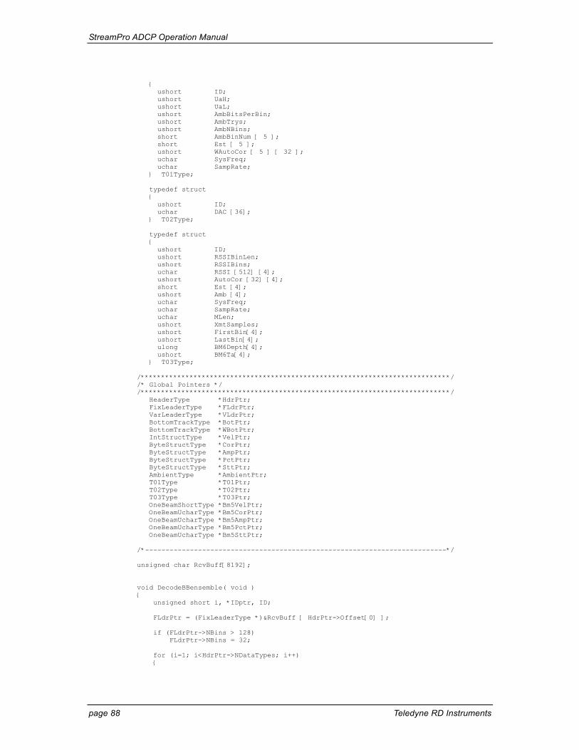
StreamPro ADCP Operation Manual
page 88 Teledyne RD Instruments
{ ushort ID; ushort UaH; ushort UaL; ushort AmbBitsPerBin; ushort AmbTrys; ushort AmbNBins; short AmbBinNum [ 5 ]; short Est [ 5 ]; ushort WAutoCor [ 5 ] [ 32 ]; uchar SysFreq; uchar SampRate; } T01Type; typedef struct { ushort ID; uchar DAC [36]; } T02Type; typedef struct { ushort ID; ushort RSSIBinLen; ushort RSSIBins; uchar RSSI [512] [4]; ushort AutoCor [32] [4]; short Est [4]; ushort Amb [4]; uchar SysFreq; uchar SampRate; uchar MLen; ushort XmtSamples; ushort FirstBin[4]; ushort LastBin[4]; ulong BM6Depth[4]; ushort BM6Ta[4]; } T03Type; /****************************************************************************/ /* Global Pointers */ /****************************************************************************/ HeaderType *HdrPtr; FixLeaderType *FLdrPtr; VarLeaderType *VLdrPtr; BottomTrackType *BotPtr; BottomTrackType *WBotPtr; IntStructType *VelPtr; ByteStructType *CorPtr; ByteStructType *AmpPtr; ByteStructType *PctPtr; ByteStructType *SttPtr; AmbientType *AmbientPtr; T01Type *T01Ptr; T02Type *T02Ptr; T03Type *T03Ptr; OneBeamShortType *Bm5VelPtr; OneBeamUcharType *Bm5CorPtr; OneBeamUcharType *Bm5AmpPtr; OneBeamUcharType *Bm5PctPtr; OneBeamUcharType *Bm5SttPtr; /*--------------------------------------------------------------------------*/ unsigned char RcvBuff[8192]; void DecodeBBensemble( void ) { unsigned short i, *IDptr, ID; FLdrPtr = (FixLeaderType *)&RcvBuff [ HdrPtr->Offset[0] ]; if (FLdrPtr->NBins > 128) FLdrPtr->NBins = 32; for (i=1; i<HdrPtr->NDataTypes; i++) {
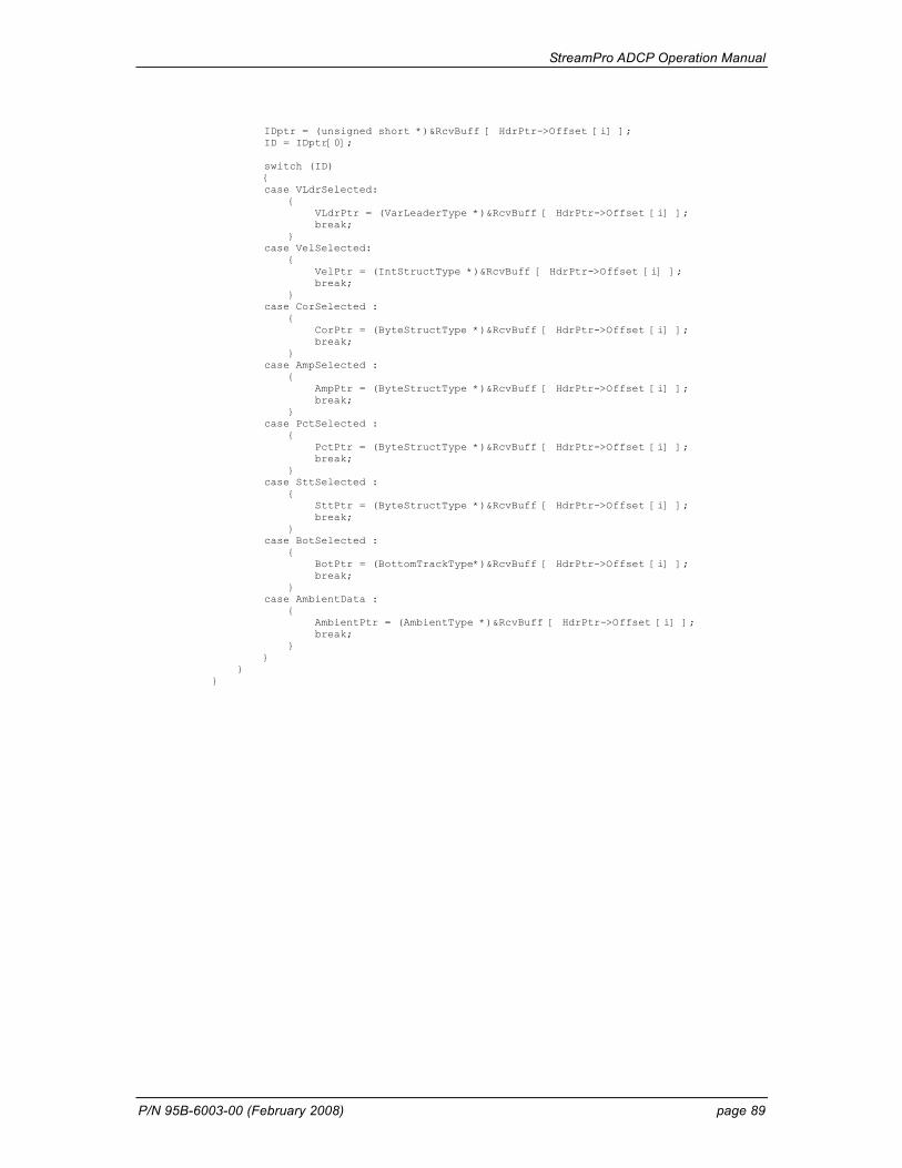
StreamPro ADCP Operation Manual
P/N 95B-6003-00 (February 2008) page 89
IDptr = (unsigned short *)&RcvBuff [ HdrPtr->Offset [i] ]; ID = IDptr[0]; switch (ID) { case VLdrSelected: { VLdrPtr = (VarLeaderType *)&RcvBuff [ HdrPtr->Offset [i] ]; break; } case VelSelected: { VelPtr = (IntStructType *)&RcvBuff [ HdrPtr->Offset [i] ]; break; } case CorSelected : { CorPtr = (ByteStructType *)&RcvBuff [ HdrPtr->Offset [i] ]; break; } case AmpSelected : { AmpPtr = (ByteStructType *)&RcvBuff [ HdrPtr->Offset [i] ]; break; } case PctSelected : { PctPtr = (ByteStructType *)&RcvBuff [ HdrPtr->Offset [i] ]; break; } case SttSelected : { SttPtr = (ByteStructType *)&RcvBuff [ HdrPtr->Offset [i] ]; break; } case BotSelected : { BotPtr = (BottomTrackType*)&RcvBuff [ HdrPtr->Offset [i] ]; break; } case AmbientData : { AmbientPtr = (AmbientType *)&RcvBuff [ HdrPtr->Offset [i] ]; break; } } } }
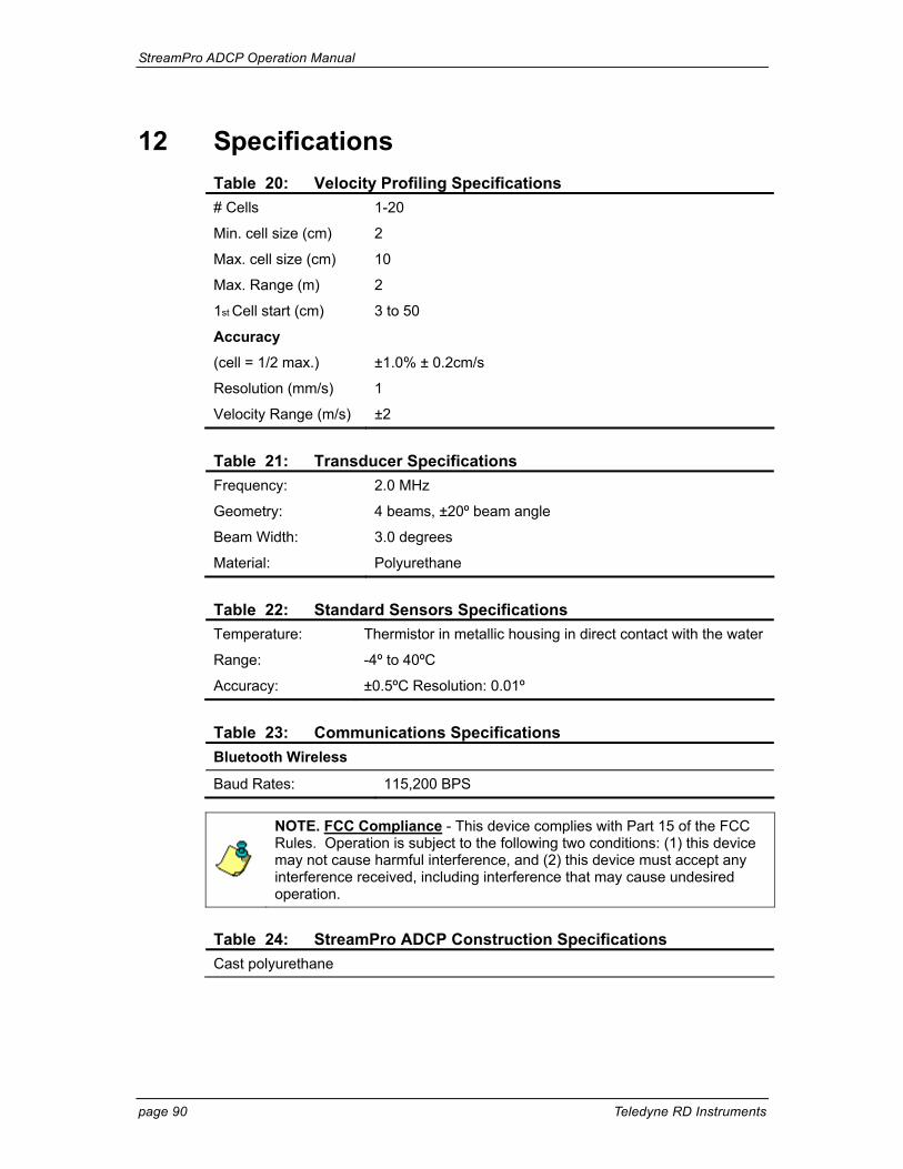
StreamPro ADCP Operation Manual
page 90 Teledyne RD Instruments
12 Specifications Table 20: Velocity Profiling Specifications # Cells 1-20
Min. cell size (cm) 2
Max. cell size (cm) 10
Max. Range (m) 2
1st Cell start (cm) 3 to 50
Accuracy
(cell = 1/2 max.) ±1.0% ± 0.2cm/s
Resolution (mm/s) 1
Velocity Range (m/s) ±2
Table 21: Transducer Specifications Frequency: 2.0 MHz
Geometry: 4 beams, ±20º beam angle
Beam Width: 3.0 degrees
Material: Polyurethane
Table 22: Standard Sensors Specifications Temperature: Thermistor in metallic housing in direct contact with the water
Range: -4º to 40ºC
Accuracy: ±0.5ºC Resolution: 0.01º
Table 23: Communications Specifications Bluetooth Wireless
Baud Rates: 115,200 BPS
NOTE. FCC Compliance - This device complies with Part 15 of the FCC Rules. Operation is subject to the following two conditions: (1) this device may not cause harmful interference, and (2) this device must accept any interference received, including interference that may cause undesired operation.
Table 24: StreamPro ADCP Construction Specifications Cast polyurethane
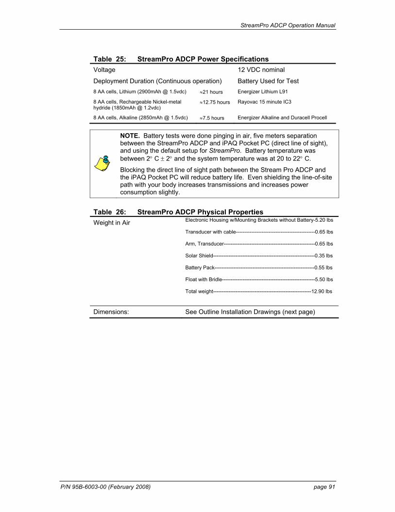
StreamPro ADCP Operation Manual
P/N 95B-6003-00 (February 2008) page 91
Table 25: StreamPro ADCP Power Specifications Voltage 12 VDC nominal
Deployment Duration (Continuous operation) Battery Used for Test 8 AA cells, Lithium (2900mAh @ 1.5vdc) ≈21 hours Energizer Lithium L91
8 AA cells, Rechargeable Nickel-metal hydride (1850mAh @ 1.2vdc)
≈12.75 hours Rayovac 15 minute IC3
8 AA cells, Alkaline (2850mAh @ 1.5vdc) ≈7.5 hours Energizer Alkaline and Duracell Procell
NOTE. Battery tests were done pinging in air, five meters separation between the StreamPro ADCP and iPAQ Pocket PC (direct line of sight), and using the default setup for StreamPro. Battery temperature was between 2° C ± 2° and the system temperature was at 20 to 22° C.
Blocking the direct line of sight path between the Stream Pro ADCP and the iPAQ Pocket PC will reduce battery life. Even shielding the line-of-site path with your body increases transmissions and increases power consumption slightly.
Table 26: StreamPro ADCP Physical Properties Weight in Air Electronic Housing w/Mounting Brackets without Battery-5.20 lbs
Transducer with cable----------------------------------------------0.65 lbs Arm, Transducer-----------------------------------------------------0.65 lbs Solar Shield-----------------------------------------------------------0.35 lbs Battery Pack----------------------------------------------------------0.55 lbs Float with Bridle------------------------------------------------------5.50 lbs Total weight---------------------------------------------------------12.90 lbs
Dimensions: See Outline Installation Drawings (next page)
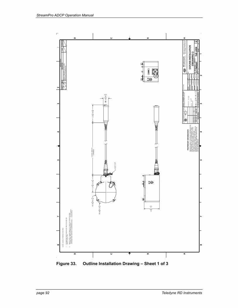
StreamPro ADCP Operation Manual
page 92 Teledyne RD Instruments
4.6
117
CA
BLE
LEN
GTH
VARI
ABL
E5.
1913
1.85
R3.1
078
.61
R3.6
392
.20
5.35
135.
8
1.53
38.9
DUS
T CA
P
1
DATE
0407
09
1/2OUT
LINE/
INST
ALL
ATIO
N
3
S. W
OLF
E
96B-
6004
NO
TES:
UN
LESS
OTH
ERW
ISE
SPEC
IFIE
D
1.
D
IMEN
SIO
NS
AN
D T
OLE
RAN
CES
ARE
IN IN
CHE
S PE
R
ASM
E Y1
4.5M
-199
4.
2.
W
EIG
HT W
ITH 1
MET
ER (D
EFA
ULT)
CA
BLE
INC
LUD
ING
BA
TTER
Y:
FO
LDED
ARM
, WITH
CO
UNTE
R BA
LAN
CE.
......
......
......
13.6
LB
[6.2
KG]
EXT
END
ED A
RM, W
ITHO
UT C
OUN
TER
BALA
NC
E....
....1
3 LB
[5.9
KG]
TITLE
:
SIZE
CA
GE
CO
DE
SHEE
T
DWG
NO
.RE
V
DA
4
A
9W05
0
87
65
43
D C B A
12
35
67
8
D C B
DO N
OT S
CA
LE D
RAW
ING
DA
TE
DATE
DATE
DA
TE
DATE
SCA
LE
TBD
APP
LIC
ATIO
N
DESC
RIPT
ION
DATE
REV
REV
ISIO
N H
ISTO
RY
ZON
E2
DRAW
N:
ENG
R/DS
GN
:
CHE
CKE
D:
APP
ROVE
D:
RELE
ASE
D
UNLE
SS O
THER
WIS
E SP
ECIF
IED:
DIM
ENSI
ON
S A
RE IN
INC
HES.
CO
NTR
AC
T NUM
BER:
TOLE
RAN
CES
:
1.5
NEX
T ASS
YUS
ED O
N
APP
ROVE
D
OF
AD
WG
CRE
ATE
D A
T TH
IS R
EV
RD In
stru
men
ts98
55 B
usin
essp
ark
Ave
.Sa
n D
iego
CA
921
31A
cout
stic
Dop
ple
r So
lutio
s
ECO
#
AN
GLE
S
END
ITEM
DRI
LLED
HO
LES:
0-
.500
+.00
5-.0
02.5
01-
1.00
0+.
007
-.004
THIR
D A
NG
LE P
ROJE
CTIO
N
THIS
DO
CUM
ENT C
ON
TAIN
S IN
FORM
ATIO
NPR
OPR
IETA
RY TO
RD
INST
RUM
ENT,
AN
DSH
ALL
NO
T BE
DIS
CLO
SED
, DUP
LIC
ATE
DO
R US
ED A
S A
BA
SIS
FOR
DES
IGN
,M
AN
UFA
CTU
RE, O
R SA
LE O
F A
PPA
RATU
SW
ITHO
UT E
XPRE
SS W
RITT
EN P
ERM
ISSI
ON
OF
RD IN
STRU
MEN
TS.
STRE
AM
PRO
2
PRO
PRIE
TARY
INFO
RMA
TION
.12
[3]
PRO
DUC
TION
REL
EASE
D.G
REEN
E
M.TE
RZIC
D.G
REEN
E
D.G
REEN
E
0407
12
0407
12
0407
12
0407
15
Figure 33. Outline Installation Drawing – Sheet 1 of 3
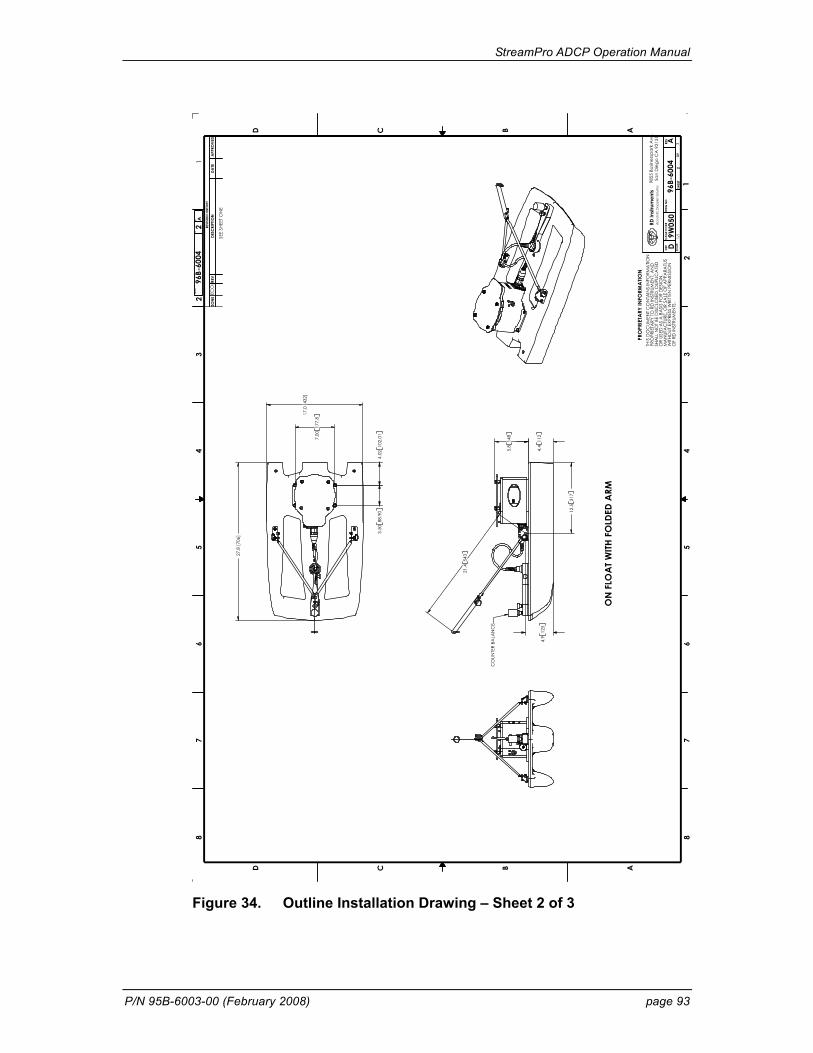
StreamPro ADCP Operation Manual
P/N 95B-6003-00 (February 2008) page 93
4.4
112
21.4
543
4.9
125
12.5
317
5.8
148
ON
FLO
AT W
ITH F
OLD
ED A
RM
CO
UNTE
R BA
LAN
CE
7.00
177.
8
4.02
102.
013.
5088
.90
17.0
[432
]
27.8
[706
]
1/1
396
B-60
04
96B-
6004
2
SIZE
CA
GE
CO
DE
SHEE
T
DWG
NO
.RE
V
DA
4
A
9W05
0
87
65
43
D C B A
12
35
67
8
D C B
SCA
LE
DESC
RIPT
ION
DATE
REV
DWG
NO
.
REV
ISIO
N H
ISTO
RY
ZON
E
SHRE
V
2A
PPRO
VED
2
OF
SEE
SHEE
T O
NE
RD In
stru
men
ts98
55 B
usin
essp
ark
Ave
.Sa
n D
iego
CA
921
31A
cout
stic
Dop
ple
r Sol
utio
s
ECO
#
THIS
DO
CUM
ENT C
ON
TAIN
S IN
FORM
ATIO
NPR
OPR
IETA
RY T
O R
D IN
STRU
MEN
T, A
ND
SHA
LL N
OT
BE D
ISC
LOSE
D, D
UPLI
CA
TED
OR
USED
AS
A B
ASI
S FO
R D
ESIG
N,
MA
NUF
AC
TURE
, OR
SALE
OF
APP
ARA
TUS
WITH
OUT
EXP
RESS
WRI
TTEN
PER
MIS
SIO
NO
F RD
INST
RUM
ENTS
.
PRO
PRIE
TARY
INFO
RMA
TION
Figure 34. Outline Installation Drawing – Sheet 2 of 3

StreamPro ADCP Operation Manual
page 94 Teledyne RD Instruments
34.0
864
ON
FLO
AT W
ITH E
XTEN
DED
ARM
1/4
396
B-60
04
96B-
6004
3
SIZE
CA
GE
CO
DE
SHEE
T
DWG
NO
.RE
V
DA
4
A
9W05
0
87
65
43
D C B A
12
35
67
8
D C B
SCA
LE
DESC
RIPT
ION
DATE
REV
DW
G N
O.
REV
ISIO
N H
ISTO
RY
ZON
E
SHRE
V
2A
PPRO
VED
3
OF
SEE
SHEE
T O
NE
RD In
stru
men
ts98
55 B
usin
essp
ark
Ave
.Sa
n D
iego
CA
921
31A
cout
stic
Dop
ple
r Sol
utio
s
ECO
#
THIS
DO
CUM
ENT
CO
NTA
INS
INFO
RMA
TION
PRO
PRIE
TARY
TO R
D IN
STRU
MEN
T, A
ND
SHA
LL N
OT
BE D
ISC
LOSE
D, D
UPLI
CA
TED
OR
USED
AS
A B
ASI
S FO
R D
ESIG
N,
MA
NUF
AC
TURE
, OR
SALE
OF
APP
ARA
TUS
WITH
OUT
EXP
RESS
WRI
TTEN
PER
MIS
SIO
NO
F RD
INST
RUM
ENTS
.
PRO
PRIE
TARY
INFO
RMA
TION
Figure 35. Outline Installation Drawing – Sheet 3 of 3
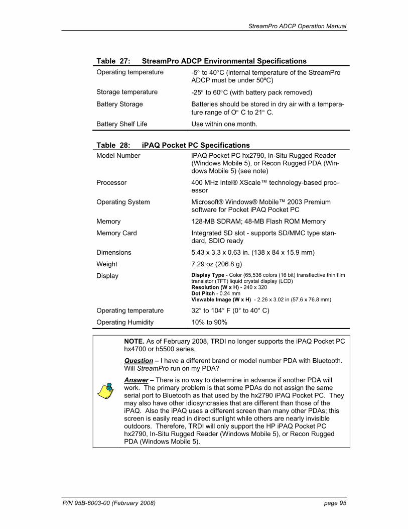
StreamPro ADCP Operation Manual
P/N 95B-6003-00 (February 2008) page 95
Table 27: StreamPro ADCP Environmental Specifications Operating temperature -5° to 40°C (internal temperature of the StreamPro
ADCP must be under 50ºC)
Storage temperature -25° to 60°C (with battery pack removed)
Battery Storage Batteries should be stored in dry air with a tempera-ture range of O° C to 21° C.
Battery Shelf Life Use within one month.
Table 28: iPAQ Pocket PC Specifications Model Number iPAQ Pocket PC hx2790, In-Situ Rugged Reader
(Windows Mobile 5), or Recon Rugged PDA (Win-dows Mobile 5) (see note)
Processor 400 MHz Intel® XScale™ technology-based proc-essor
Operating System Microsoft® Windows® Mobile™ 2003 Premium software for Pocket iPAQ Pocket PC
Memory 128-MB SDRAM; 48-MB Flash ROM Memory
Memory Card Integrated SD slot - supports SD/MMC type stan-dard, SDIO ready
Dimensions 5.43 x 3.3 x 0.63 in. (138 x 84 x 15.9 mm)
Weight 7.29 oz (206.8 g)
Display Display Type - Color (65,536 colors (16 bit) transflective thin film transistor (TFT) liquid crystal display (LCD) Resolution (W x H) - 240 x 320 Dot Pitch - 0.24 mm Viewable Image (W x H) - 2.26 x 3.02 in (57.6 x 76.8 mm)
Operating temperature 32° to 104° F (0° to 40° C)
Operating Humidity 10% to 90%
NOTE. As of February 2008, TRDI no longer supports the iPAQ Pocket PC hx4700 or h5500 series.
Question – I have a different brand or model number PDA with Bluetooth. Will StreamPro run on my PDA?
Answer – There is no way to determine in advance if another PDA will work. The primary problem is that some PDAs do not assign the same serial port to Bluetooth as that used by the hx2790 iPAQ Pocket PC. They may also have other idiosyncrasies that are different than those of the iPAQ. Also the iPAQ uses a different screen than many other PDAs; this screen is easily read in direct sunlight while others are nearly invisible outdoors. Therefore, TRDI will only support the HP iPAQ Pocket PC hx2790, In-Situ Rugged Reader (Windows Mobile 5), or Recon Rugged PDA (Windows Mobile 5).
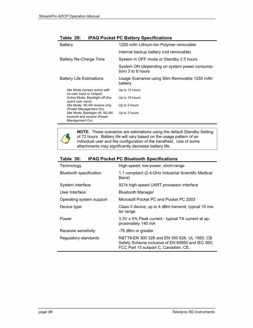
StreamPro ADCP Operation Manual
page 96 Teledyne RD Instruments
Table 29: iPAQ Pocket PC Battery Specifications Battery 1250 mAh Lithium-Ion Polymer removable
Internal backup battery (not removable)
Battery Re-Charge Time System in OFF mode or Standby 2.5 hours
System ON (depending on system power consump-tion) 3 to 6 hours
Battery Life Estimations Usage Scenarios using Slim Removable 1250 mAh battery
Idle Mode (screen active with no user Input or Output)
Up to 12 hours
Active Mode, Backlight off (fre-quent user input)
Up to 10 hours
Idle Mode, WLAN receive only (Power Management On)
Up to 3 hours
Idle Mode, Backlight off, WLAN transmit and receive (Power Management On)
Up to 3 hours
NOTE. These scenarios are estimations using the default Standby Setting of 72 hours. Battery life will vary based on the usage pattern of an individual user and the configuration of the handheld. Use of some attachments may significantly decrease battery life.
Table 30: iPAQ Pocket PC Bluetooth Specifications Technology High-speed, low-power, short-range
Bluetooth specification 1.1 compliant (2.4-GHz Industrial Scientific Medical Band)
System interface 921k high-speed UART processor interface
User Interface Bluetooth Manager
Operating system support Microsoft Pocket PC and Pocket PC 2003
Device type Class II device; up to 4 dBm transmit, typical 10 me-ter range
Power 3.3V ± 5% Peak current - typical TX current at ap-proximately 140 mA
Receiver sensitivity -78 dBm or greater
Regulatory standards R&TT#-EN 300 328 and EN 300 826, UL 1950, CB Safety Scheme inclusive of EN 60950 and IEC 950, FCC Part 15 subpart C, Canadian, CE,
StreamPro ADCP Operation Manual
P/N 95B-6003-00 (February 2008) page 97
Table 31: Software Requirements Microsoft ActiveSync Windows XP®, Windows 2000®, Windows ME®,
Windows NT 4.0® with Service Pack 6 installed, or Windows 98®
Microsoft Outlook 98 or later required for synchroni-zation to the PC (Outlook 2003 is recommended)
Microsoft Internet Explorer 4.01 SP1 or later (re-quired)
12 to 65 MB Free Disk Space
One Serial Port or USB Port (recommended)
CD-ROM Drive
VGA graphics card with 256 color or higher
StreamPro iPAQ Pocket PC hx2790 series, In-Situ Rugged Reader (Windows Mobile 5), or Recon Rugged PDA (Windows Mobile 5).
NOTE. Please register your iPAQ Pocket PC as soon as you verify it is functional. Register your iPAQ Pocket PC at http://www.register.hp.com in order to receive warranty protection and updates.
NOTE. If the iPAQ Pocket PC fails “out of the box” or within 30 days of delivery (accidental damage caused by the customer is not covered), then TRDI will replace the iPAQ Pocket PC and handle the warranty issue with HP directly.
NOTE. If the iPAQ Pocket PC is damaged or fails after 30 days of use, then contact HP directly.
The iPAQs come with a one-year parts and labor warranty that has a turn around time of 5 to 7 Business days from when the iPAQ has been received by the HP repair center. HP has Carepaqs units that will provide next business day exchange service (again, from when the unit has been received) for three years as well as service that covers accidental damage for an additional cost. Please contact HP Customer Care at 800-888-0292 Opt 5, then Option 2.
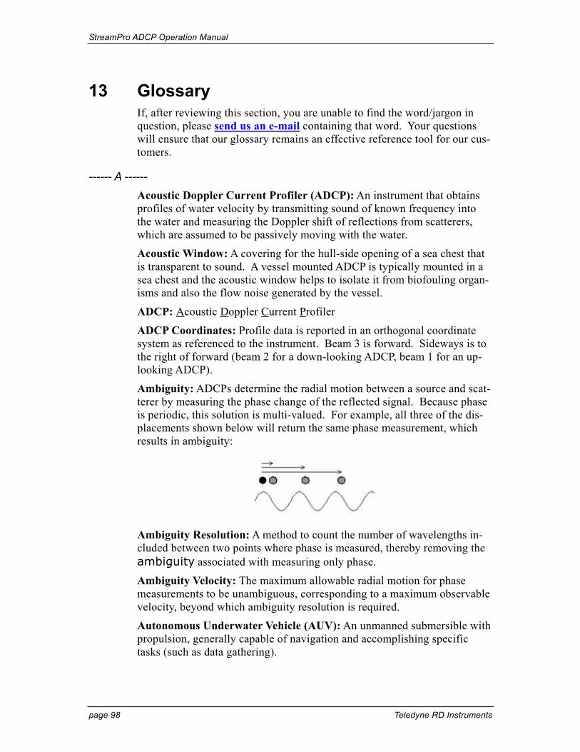
StreamPro ADCP Operation Manual
page 98 Teledyne RD Instruments
13 Glossary If, after reviewing this section, you are unable to find the word/jargon in question, please send us an e-mail containing that word. Your questions will ensure that our glossary remains an effective reference tool for our cus-tomers.
------ A ------ Acoustic Doppler Current Profiler (ADCP): An instrument that obtains profiles of water velocity by transmitting sound of known frequency into the water and measuring the Doppler shift of reflections from scatterers, which are assumed to be passively moving with the water.
Acoustic Window: A covering for the hull-side opening of a sea chest that is transparent to sound. A vessel mounted ADCP is typically mounted in a sea chest and the acoustic window helps to isolate it from biofouling organ-isms and also the flow noise generated by the vessel.
ADCP: Acoustic Doppler Current Profiler
ADCP Coordinates: Profile data is reported in an orthogonal coordinate system as referenced to the instrument. Beam 3 is forward. Sideways is to the right of forward (beam 2 for a down-looking ADCP, beam 1 for an up-looking ADCP).
Ambiguity: ADCPs determine the radial motion between a source and scat-terer by measuring the phase change of the reflected signal. Because phase is periodic, this solution is multi-valued. For example, all three of the dis-placements shown below will return the same phase measurement, which results in ambiguity:
Ambiguity Resolution: A method to count the number of wavelengths in-cluded between two points where phase is measured, thereby removing the ambiguity associated with measuring only phase.
Ambiguity Velocity: The maximum allowable radial motion for phase measurements to be unambiguous, corresponding to a maximum observable velocity, beyond which ambiguity resolution is required.
Autonomous Underwater Vehicle (AUV): An unmanned submersible with propulsion, generally capable of navigation and accomplishing specific tasks (such as data gathering).
StreamPro ADCP Operation Manual
P/N 95B-6003-00 (February 2008) page 99
AUV: Autonomous Underwater Vehicle
------ B ------ Backscatter: 1) The portion of a sound wave that is reflected by scatterers directly back toward the source. 2) A qualitative measurement (in decibels) of scatterer concentration which is calculated in the WinRiver software. This calculation corrects the echo intensity data for sound absorption, beam spreading, transducer temperature, etc. and provides an excellent means of tracking relative concentration (e.g. “Is most of the sediment in the water here or is it there?”). Obtaining a quantitative measurement (e.g. “How many mg/L of bottom sediment are in this parcel of water?”) requires a field calibration at the measurement site. There is a third-party software pack-age, Sediview, designed for this task.
BBBatch: Utility program to allow automated conversion of a series of raw binary ADCP files to ASCII files.
BBCheck: Utility program that checks the integrity and quality of raw bi-nary ADCP files.
BBConv: Utility program to convert some portion of a raw binary ADCP file into an ASCII file using a decoder file. Several decoder files are in-cluded on the TRDI Tools CD, for example: extract only distance to first bin, extract only navigation data, etc. Complete documentation on these decoder files as well as information on how to write your own is available.
BBList: Utility program for viewing and converting raw binary ADCP data files. It is a menu-driven program offering a step-by-step process to convert raw binary files to ASCII files.
BBMerge: Utility program to convert comma-delimited ASCII files back into raw binary ADCP format.
BBSlice: A raw data sub-sectioning utility program. BBSlice converts a raw data file into a series of ASCII files, opening a new ASCII file when-ever there is a jump in the sequence of ensemble numbers.
BBss: Utility program to calculate the speed of sound when given tempera-ture, salinity and depth.
BBSub: A raw data sub-sectioning utility program. BBSub allows you to extract subsets of raw data from a large raw data file by choosing the start-ing and ending ensemble number.
BBTalk: Terminal emulator program for direct communication with the CPU of an ADCP or DVL.
Beam Angle: The angle between a transducer beam’s main axis and the ver-tical axis of the ADCP or DVL (typically 20 or 30º).
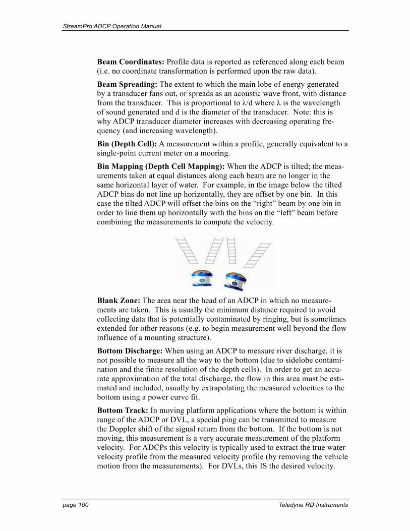
StreamPro ADCP Operation Manual
page 100 Teledyne RD Instruments
Beam Coordinates: Profile data is reported as referenced along each beam (i.e. no coordinate transformation is performed upon the raw data).
Beam Spreading: The extent to which the main lobe of energy generated by a transducer fans out, or spreads as an acoustic wave front, with distance from the transducer. This is proportional to λ/d where λ is the wavelength of sound generated and d is the diameter of the transducer. Note: this is why ADCP transducer diameter increases with decreasing operating fre-quency (and increasing wavelength).
Bin (Depth Cell): A measurement within a profile, generally equivalent to a single-point current meter on a mooring.
Bin Mapping (Depth Cell Mapping): When the ADCP is tilted; the meas-urements taken at equal distances along each beam are no longer in the same horizontal layer of water. For example, in the image below the tilted ADCP bins do not line up horizontally, they are offset by one bin. In this case the tilted ADCP will offset the bins on the “right” beam by one bin in order to line them up horizontally with the bins on the “left” beam before combining the measurements to compute the velocity.
Blank Zone: The area near the head of an ADCP in which no measure-ments are taken. This is usually the minimum distance required to avoid collecting data that is potentially contaminated by ringing, but is sometimes extended for other reasons (e.g. to begin measurement well beyond the flow influence of a mounting structure).
Bottom Discharge: When using an ADCP to measure river discharge, it is not possible to measure all the way to the bottom (due to sidelobe contami-nation and the finite resolution of the depth cells). In order to get an accu-rate approximation of the total discharge, the flow in this area must be esti-mated and included, usually by extrapolating the measured velocities to the bottom using a power curve fit.
Bottom Track: In moving platform applications where the bottom is within range of the ADCP or DVL, a special ping can be transmitted to measure the Doppler shift of the signal return from the bottom. If the bottom is not moving, this measurement is a very accurate measurement of the platform velocity. For ADCPs this velocity is typically used to extract the true water velocity profile from the measured velocity profile (by removing the vehicle motion from the measurements). For DVLs, this IS the desired velocity.
StreamPro ADCP Operation Manual
P/N 95B-6003-00 (February 2008) page 101
Bottom Track Modes: There are currently four bottom tracking modes of operation available from TRDI:
Bottom Mode 4: Uses ambiguity resolution, and adjusts lags for re-duced variance at higher elevations (or deeper depths).
Bottom Mode 5: Specifically designed for reduced variance in shal-low water/low elevations. It transmits several pings with computa-tions to best determine depth and speed. This mode is the default mode, but it will automatically switch to Bottom Mode 4 if condi-tions warrant.
Bottom Mode 6: Offers special narrow bandwidth operation to re-duce the potential for interference or for stealth. No ambiguity reso-lution, instead bottom mode 6 requires user input of an approximate operating elevation (or depth).
Bottom Mode 7: Similar to bottom mode 5, except that it is opti-mized for slow-moving platforms in very shallow, high backscatter environments.
Break: A wake up command to an ADCP or DVL that places the instrument in command mode.
Broadband ADCP: An ADCP that uses broadband processing.
Broadband Processing: Use of coded pulses to make multiple measure-ments of phase with a single ping, and thereby greatly increase the precision of the measurement.
------ C ------ Channel Master: Model name for an ADCP designed to use horizontal profiling for flow monitoring in inland waterways.
Command Mode: The state into which an ADCP or DVL goes upon receiv-ing a break. In this mode the ADCP or DVL is waiting to receive a com-mand. It draws relatively high power, so the ADCP or DVL will go to sleep if no command is received for five minutes.
Correlation: A key quality control parameter, this is essentially a meas-urement of how much the particle distribution has changed between phase measurements. The less the distribution has changed, the higher the corre-lation, and the more precise the velocity measurement.
------ D ------ Dead Reckoning: A navigation method where position is estimated by measuring velocity, heading and time from the last known position.
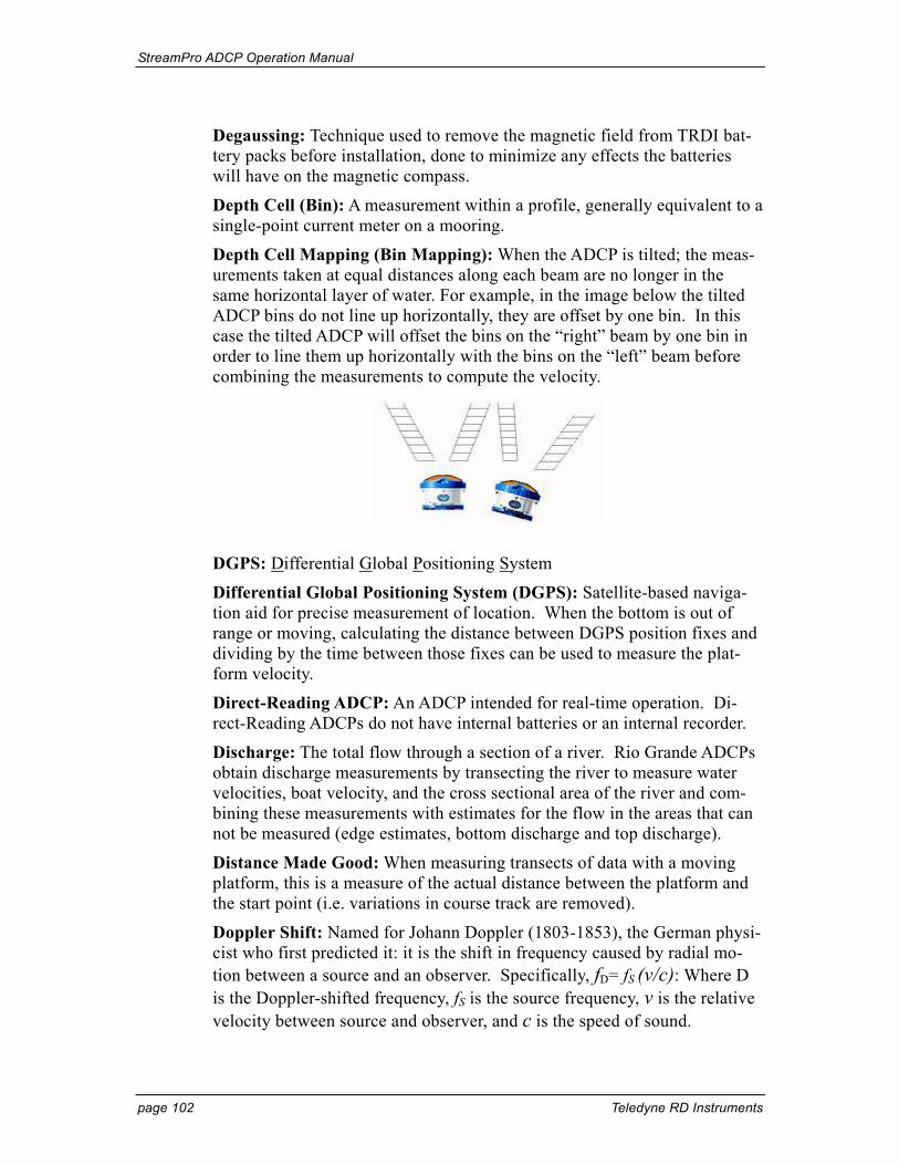
StreamPro ADCP Operation Manual
page 102 Teledyne RD Instruments
Degaussing: Technique used to remove the magnetic field from TRDI bat-tery packs before installation, done to minimize any effects the batteries will have on the magnetic compass.
Depth Cell (Bin): A measurement within a profile, generally equivalent to a single-point current meter on a mooring.
Depth Cell Mapping (Bin Mapping): When the ADCP is tilted; the meas-urements taken at equal distances along each beam are no longer in the same horizontal layer of water. For example, in the image below the tilted ADCP bins do not line up horizontally, they are offset by one bin. In this case the tilted ADCP will offset the bins on the “right” beam by one bin in order to line them up horizontally with the bins on the “left” beam before combining the measurements to compute the velocity.
DGPS: Differential Global Positioning System
Differential Global Positioning System (DGPS): Satellite-based naviga-tion aid for precise measurement of location. When the bottom is out of range or moving, calculating the distance between DGPS position fixes and dividing by the time between those fixes can be used to measure the plat-form velocity.
Direct-Reading ADCP: An ADCP intended for real-time operation. Di-rect-Reading ADCPs do not have internal batteries or an internal recorder.
Discharge: The total flow through a section of a river. Rio Grande ADCPs obtain discharge measurements by transecting the river to measure water velocities, boat velocity, and the cross sectional area of the river and com-bining these measurements with estimates for the flow in the areas that can not be measured (edge estimates, bottom discharge and top discharge).
Distance Made Good: When measuring transects of data with a moving platform, this is a measure of the actual distance between the platform and the start point (i.e. variations in course track are removed).
Doppler Shift: Named for Johann Doppler (1803-1853), the German physi-cist who first predicted it: it is the shift in frequency caused by radial mo-tion between a source and an observer. Specifically, fD= fS (v/c): Where D is the Doppler-shifted frequency, fS is the source frequency, v is the relative velocity between source and observer, and c is the speed of sound.
StreamPro ADCP Operation Manual
P/N 95B-6003-00 (February 2008) page 103
Doppler Velocity Log (DVL): An instrument designed to measure the ve-locity and elevation of a moving platform with bottom tracking. Most DVLs will switch to measuring velocity relative to the water when the bot-tom is out of range.
DVL: Doppler Velocity Log.
------ E ------ Earth Coordinates: Profile data is reported in an orthogonal coordinate frame as referenced to the Earth (East, North and Up). “North” can mean magnetic or true, depending on the heading input.
Echo Intensity: A key quality control parameter, echo intensity is a meas-ure of the signal strength intensity returned to the transducer. High echo intensity can show solid targets (e.g. a boundary, obstruction or fish), while low echo intensity can show insufficient scatterers or the limits of profiling range for the environment.
Edge Estimate: When measuring river discharge with an ADCP it is not possible to measure to zero depth at the banks of the river. The flow through this unmeasured area must be approximated in order to obtain an accurate estimate of the total discharge.
Ensemble: A group of measurements (pings) considered together. An en-semble is usually the average of the individual measurements, and has a higher precision than any individual measurement.
Error Velocity: A key quality control parameter that derives from the four beam geometry of an ADCP. Each pair of opposing beams provides one measurement of the vertical velocity and one component of the horizontal velocity, so there are actually two independent measurements of vertical velocity that can be compared. If the flow field is homogeneous, the differ-ence between these vertical velocities will average to zero. To put the error velocity on a more intuitive footing, it is scaled to be comparable to the variance in the horizontal velocity. In a nutshell, the error velocity can be treated as an indication of the standard deviation of the horizontal velocity measurements.
------ F ------ Fish Detection Threshold: Used to identify and mark as bad any velocity measurement that was potentially contaminated by a fish (because fish are generally not passively following the flow). It is a flag on the maximum allowable value for the measured echo intensity return.
Frequency: The number of wave crests passing a given point per unit time.
StreamPro ADCP Operation Manual
page 104 Teledyne RD Instruments
------ G ------ Gimbals: Frame that will support the weight of an object but allow its free rotation. Gimbals can be constructed to allow free rotation in one, two, or three axes.
Gyro: A rapidly spinning device mounted on gimbals to maintain a constant orientation. These devices are commonly used to measure heading on ships because, unlike magnetic compasses, they are unaffected by ferrous metals or by varying electromagnetic fields. They can also be used to measure pitch and roll because, unlike liquid level sensors, they are unaffected by accelerations.
------ H ------ Homogeneity: The extent to which the current measured by all four beams is the same. A key assumption of all ADCP processing is that the currents are horizontally homogeneous across the four beams. This assumption is checked for each measurement by using the error velocity measurement.
Horizontal ADCP (H-ADCP): Instrument designed to measure velocity profiles in a horizontal plane.
------ I ------ Inertial Navigation: Method for estimating the attitude and position of a moving platform (of primary interest here are AUVs) by integrating meas-urements from gyros and accelerometers. This integration is subject to large errors over time, so DVLs and pressure sensors are commonly incor-porated as external inputs to measure and correct these errors.
------ J ------
------ K ------
------ L ------ Lag: A time delay between pulses or pings.
Long Ranger: Model name for Workhorse ADCPs of frequency 75 kHz.
Lowered ADCP (L-ADCP): Technique whereby one or two ADCPs are lowered through the water column (typically on a rosette) to obtain velocity profiles over the full ocean depth. Note that a whole body of research exists on how to properly remove the motion of the rosette from the velocity measurements obtained in this manner.
StreamPro ADCP Operation Manual
P/N 95B-6003-00 (February 2008) page 105
------ M ------ Main Lobe: The main focus of energy emitted from a transducer. If the transducer were a flashlight, the main lobe would be the visible beam of light.
Mariner: Model name for a Workhorse Monitor ADCP configured for un-derway current measurement in shallow water (as opposed to the deep water Ocean Surveyor systems).
Modes: TRDI offers several modes of operation that are optimized for cer-tain conditions. There are currently five modes of operation for water pro-filing available from TRDI:
Mode 1: General purpose water profiling. This is the most robust profiling mode, designed for the widest variety of measurement ap-plications. Mode 1 can resolve high velocities and can measure over long ranges.
Mode 5: For high resolution profiling in shallow water with low flows. Mode 5 should be used with bottom tracking. It offers the lowest standard deviation per measurement, but is also the most lim-ited in its allowed performance envelope (e.g. low velocity flow, slow platform movement, no high shears or turbulence).
Mode 8: Also for high resolution profiling in shallow water. Mode 8 should also be used with bottom tracking. It has higher standard deviation per measurement than mode 5, but allows a somewhat wider performance envelope.
Mode 11: The latest in our high resolution profiling modes. In-tended for the shallowest water, it is also well suited for boundary layer studies. Mode 11 should be used with bottom tracking. It al-lows smaller depth cells (1 cm), more depth cells, and has improved signal processing which allows faster ping rates and a wider per-formance envelope than modes 5 and 8. Mode 11 is intended to su-percede mode 5.
Mode 12: Offers increased resolution (1 cm depth cells) and uses multiple sub-pings to improve the standard deviation of each meas-urement. Mode 12 allows measurement of fast moving, shallow wa-ter; and can also be used to improve the standard deviations of any measurement (any range, any velocity) when the ADCP heading is fixed or reasonably steady.
Monitor: Model name for a direct reading Workhorse ADCP.
Moving Bottom: Some rivers carry such a heavy sediment load that they do not have a clearly identifiable bottom. In essence, the mud just keeps getting thicker and slower with depth. In such environments it is not un-
StreamPro ADCP Operation Manual
page 106 Teledyne RD Instruments
common for bottom tracking measurements to lock onto a sediment layer that is still moving, resulting in a bias to the bottom tracking velocity. This is especially important for river discharge measurements, where the vessel’s navigation must be substituted for the bottom track velocity to obtain accu-rate results.
------ N ------ Navigator: Model name for the TRDI Doppler Velocity Log.
Narrowband ADCP: An ADCP that uses narrowband processing.
Narrowband Processing: Uses a single pulse per ping to measure velocity. The lack of coding in the pulse makes a narrowband measurement much less precise, but it allows profiling over a longer range. Narrowband proc-essing generally requires much larger ensembles to get a precise measure-ment.
------ O ------ Ocean Observer: Low frequency Phased Array ADCP for cabled deploy-ment, usually from an oilrig.
Ocean Surveyor: Low frequency Phased Array ADCP for vessel-mounted operations.
------ P ------ Percent Good: A key quality control parameter, percent good indicates what fraction of the pings passed the various error thresholds. Each depth cell reports four values for percent good, and the meaning depends on the coordinate frame. If data is collected in beam coordinates, then the four percent good values represent the percentage of the pings collected by each beam for that depth cell whose correlation exceeded a low correlation threshold. In the other coordinate frames (ADCP, Ship and Earth Coordi-nates), the four Percent Good values represent (in order): 1) The percentage of good three beam solutions (one beam rejected); 2) The percentage of good transformations (error velocity threshold not exceeded); 3) The per-centage of measurements where more than one beam was bad; and 4) The percentage of measurements with four beam solutions.
Phase: An engineering measure of the propagation delay caused by radial motion between scatterer and source. Phase is ambiguous in that it is cycli-cal (e.g. 10 º is the same phase as 370 º).
Phased Array Transducer: A single, flat, multi-element transducer that uses a TRDI proprietary technique to simultaneously form all four beams. Available phased array transducers are generally low frequency (38 kHz, 75 kHz and 150 kHz) long range devices.
StreamPro ADCP Operation Manual
P/N 95B-6003-00 (February 2008) page 107
Ping: The entirety of the sound generated by an ADCP transducer for a sin-gle measurement cycle. A broadband ping contains a coded series of pulses and lags, while a narrowband ping contains a single pulse.
Ping Mode: Power conserving mode for a deployed ADCP or DVL, where only the power needed for the immediate deployment task is drawn (as op-posed to command mode, where the ADCP consumes considerable power while simply waiting for input). This mode saves the deployment configu-ration so that, in the event of a power interruption, the ADCP or DVL will be able to automatically resume the configured deployment upon return of power.
PlanADCP: Windows-based software package allowing the user to config-ure, and evaluate the consequences of, a deployment command-set for an ADCP.
Profile: A series of regularly spaced depth cells in which the ADCP meas-ures velocity along with several quality control parameters.
Pulse: A sound wave generated by a transducer.
Propagation Delay: The change in the travel time of sound between a source and scatterer, generally due to radial motion. As an example: if it takes longer for sound to reflect back from a scatterer than it did a short while ago (and the speed of sound has not changed), then the scatterer must be getting farther away.
------ Q ------ Quartermaster: The model name for a self-contained 150kHz Workhorse ADCP.
------ R ------ Radial Motion: Movement which alters the distance between source and scatterer.
Range: The maximum profile length of an ADCP, it depends on several fac-tors (note that these factors are inter-related in a complex way, and the gen-eralizations below are intended only as rules of thumb – use PlanADCP to check specific combinations):
1. Frequency: the lower the frequency, the longer the range.
2. Depth cell size: the larger the cell, the longer the range.
3. Mode of operation: mode 1 has the longest range.
4. Bandwidth: the narrower the bandwidth, the longer the range.
5. Concentration of scatterers: generally, the more scatterers, the longer the range.
StreamPro ADCP Operation Manual
page 108 Teledyne RD Instruments
6. Temperature: generally, the colder the water, the longer the range.
7. Salinity: generally, the fresher the water, the longer the range.
Range Gating: After sending a ping into the water, the ADCP transducers listen for returned signal. The time series of the returned signal is then bro-ken into a sequence of time segments, or range gates. Each segment is equivalent to a depth cell, with the last segment coming from the farthest range from the ADCP.
RDI Tools: Software package containing all of the BB* programs (BBTalk, BBList, etc.) as well as several commonly used decoder files.
Reference Layer: In moving platform applications where the bottom is out of range, the vessel motion can be approximated by assuming the water is motionless at some point in the measured profile. This point is the refer-ence layer.
Remotely Operated Vehicle (ROV): unmanned submersible controlled by an operator via a tethering cable.
Ringing: After transmission the ADCP electronics, transducer and immedi-ate surrounding equipment (particularly in vessel mounted ADCPs) all re-quire some finite time to dampen the transmit energy, during which time any signal return from scatterers will be contaminated.
Rio Grande ADCP: The model name for an ADCP optimally configured for measurement of river discharge. A distinguishing feature of Rio Grande ADCPs is that they are designed to operate from a 12 VDC power supply (all other ADCPs operate from 20 – 50 VDC).
Rosette: Oceanographic instrumentation package found on most research vessels. Rosettes are designed to be lowered to depths of interest while col-lecting data of various types. Most Lowered-ADCPs are mounted on ro-settes.
ROV: Remotely Operated Vehicle
------ S ------ Scatterers: Small particles or plankton in the water which reflect sound waves.
Sea Chest: Cavity in the hull of a vessel to allow stream-lined, recessed mounting of equipment such as a Vessel Mount ADCP.
Sediview: Third party software designed to use ADCP echo intensity meas-urements and in situ sampling to obtain quantitative estimates of sediment concentration.
StreamPro ADCP Operation Manual
P/N 95B-6003-00 (February 2008) page 109
Self-Contained ADCP: An ADCP equipped with internal batteries and an internal recorder for autonomous operation.
Sentinel: The model name for a self-contained Workhorse ADCP.
Ship Coordinates: Profile data is reported in an orthogonal coordinate frame as referenced to the ship (if beam 3 is forward then ship coordinates are the same as instrument coordinates).
Sidelobes: Peaks in sound intensity generated by a transducer found to the side of the main lobe.
Sidelobe Contamination: This only need be considered when operating an ADCP near a boundary (e.g. in shallow water). The beam angle of the main lobe of an ADCP transducer is 20 or 30º off the vertical, which means that the distance to the boundary along the ADCP centerline is shorter than the distance to the boundary along a beam. Because most boundaries will re-flect very strongly (much more strongly than the scatterers), sidelobe en-ergy can travel the shorter path directly to the surface and thereby include the “velocity” of the boundary with the velocity measurements taken along the beams at any longer distance. This potential for interference depends strictly on the beam angle. An ADCP with a 20º beam angle has the poten-tial for sidelobe contamination at (distance to the boundary)*cos(20º), or equivalently, the last 6% of the profile. Note: Sidelobe contamination is not relevant for DVLs, which specifically look for the bottom.
Software Break: When using radio or acoustic telemetry, it is usually not possible to send a break signal. Under these circumstances an ADCP can be configured to recognize a series of keystrokes (i.e. = = =) as a break.
Source: Originator of sound of known frequency, here typically the trans-ducer of an ADCP.
StreamPro: Model name for ADCP designed for discharge measurement in shallow waterways.
------ T ------ Top Discharge: When using an ADCP to measure river discharge, it is not possible to measure all the way to the surface (due to the blank zone and to the need to mount the transducers at sufficient depth to remain submerged with no air entraining past the transducers). In order to get an accurate ap-proximation of the total discharge, the flow in this area must be estimated and included, usually by extrapolating the measured velocities to the sur-face.
Transducer: A device to convert electrical energy into sound waves, and vice versa.
StreamPro ADCP Operation Manual
page 110 Teledyne RD Instruments
------ U ------ Unmanned Underwater Vehicle (UUV): Generic term referring to both AUVs and ROVs.
UUV: Unmanned Underwater Vehicle
------ V ------ Vessel Mount: An ADCP mounted to the hull of a vessel, typically in a sea chest, and having inputs from the vessel’s navigation equipment.
VM-DAS: Windows-based data acquisition package for vessel mount ADCPs. This package includes the ability to incorporate the ship’s naviga-tion equipment.
------ W ------ Wavelength: The distance between successive wave crests in a sound wave.
WinADCP: Windows-based post-processing package for ADCP data.
WinH-ADCP: Windows-based data acquisition and playback package for Horizontal ADCPs.
WinRiver: Windows-based software package for real time ADCP data gathering. It is designed primarily for measurement of river discharge and allows integration of the platform’s navigation equipment. It also converts echo intensity measurements to qualitative estimates of backscatter.
WinSC: Windows-based software package for self-contained ADCPs in-cludes configuring, testing, data recovery and viewing options.
Workhorse ADCP: The generic model name for all of the non-phased ar-ray broadband ADCPs currently produced by TRDI.
------ X ------ Xdcr: A common abbreviation for transducer.
------ Y ------
------ Z ------ ZedHed: TRDI trade name for a transducer designed to minimize ringing.

StreamPro ADCP Operation Manual
P/N 95B-6003-00 (February 2008) page 111
NOTES

StreamPro ADCP Operation Manual
page 112 Teledyne RD Instruments
NOTES