strength of materials · 2019-11-19 · mechanics of materials or strength of materials is central...
TRANSCRIPT

STRENGTH OF MATERIALS
For MECHANICAL ENGINEERING
CIVIL ENGINEERING


SYLLABUS Stress and strain, elastic constants, Poisson's ratio; Mohr’s circle for plane stress and plane strain; thin cylinders; shear force and bending moment diagrams; bending and shear stresses; deflection of beams; torsion of circular shafts; Euler’s theory of columns; energy methods; thermal stresses; strain gauges and rosettes; testing of materials with universal testing machine; testing of hardness and impact strength.
ANALYSIS OF GATE PAPERS
MECHANICAL
Exam Year 1 Mark Ques.
2 Mark Ques. Total
2003 6 4 14 2004 3 4 11 2005 2 6 14 2006 2 5 12 2007 2 6 14 2008 4 8 20 2009 2 2 6 2010 1 2 5 2011 4 3 10 2012 3 3 9 2013 2 1 4
2014 Set-1 2 3 8 2014 Set-2 3 2 7 2014 Set-3 2 2 6 2014 Set-4 2 2 6 2015 Set-1 3 2 5 2015 Set-2 2 5 12 2015 Set-3 1 1 3 2016 Set-1 3 4 11 2016 Set-2 2 4 10 2016 Set-3 2 3 8 2017 Set-1 5 4 13 2017 Set-2 3 4 7 2018 Set-1 4 5 14 2018 Set-2 2 4 10
CIVIL
Exam Year 1 Mark Ques.
2 Mark Ques. Total
2003 2 5 12 2004 1 6 13 2005 2 3 8 2006 3 9 21 2007 3 5 13 2008 1 8 17 2009 2 5 12 2010 5 2 9 2011 1 3 7 2012 3 3 9 2013 2 2 9
2014 Set-1 1 3 7 2014 Set-2 1 5 11 2015 Set-1 2 2 6 2015 Set-2 2 2 6 2016 Set-1 3 6 2016 Set-2 4 8 2017 Set-1 2 2 6 2017 Set-2 1 4 9 2018 Set-1 1 3 7 2018 Set-2 1 2 5
STRENGTH OF MATERIALS
© Copyright Reserved by Gateflix.in No part of this material should be copied or reproduced without permission
Topics Page No 1. SIMPLE STRESS AND STRAIN 1.1 Introduction 1
1.2 Stresses and Strains 1 1.3 Types of stress and strain 2 1.4 Hook’s law and Elastic Property 5 1.5 True Stress and True Strain 5 1.6 Elastic Constants 6 1.7 Types of Materials 7 1.8 Strain Under Tri Axial Loading 7 1.9 Axial Stress in Compound Bars 7 1.10 Elongation of the Taper Beam under Axial Load 8 1.11 Elongation Due to Self-Weight of the Body 9 1.12 Thermal Stress 9 Gate Questions 11
2. STRAIN ENERGY AND IMPACT LOAD
2.1 Strain Energy 29 Gate Questions 31
3. SHEAR FORCE AND BENDING MOMENT DIAGRAM
3.1 Shear Force and Bending Moment 34 3.2 Beam 35 3.3 Free Body Diagram 37 3.4 Method of Analysis 37 3.5 Equations of Equilibrium 37 3.6 Example Problems 37 3.7 Special Case of Shear Force Diagram and Bending Moment 39 Gate Questions 46
4. BENDING STRESS AND SHEAR STRESS
4.1 Pure Bending Moment 49 4.2 Beam under Uniform Strength 50 4.3 Direct Shear Stress 51 Gate Questions 54
5. PURE TORSION
CONTENTS
© Copyright Reserved by Gateflix.in No part of this material should be copied or reproduced without permission
5.1 Pure Torsion 70 5.2 Composite Shafts 71 5.3 Spring 73 5.4 Connection of Springs 76 Gate Questions 77 6. COMBINED STRESS AND STRAIN 6.1 Introduction 88 6.2 Normal Stress and Shear Stress 88 6.3 Principal Planes and Principal Stress 88 6.4 Maximum Shear Stress Plane and Maximum Shear Stress 88 6.5 Principal Strain and Shear strain 89 6.6 Combined Bending & Torsion 89 6.7 Mohr’s circle 90 Gate Questions 91 7. COLUMN AND PRESSURE VESSEL 7.1 Introduction 95 7.2 Types of Column 95 7.3 Slenderness ratio 95 7.4 Load analysis of column 95 7.5 Pressure vessel 96 Gate Questions 100 8. SLOPE AND DEFLECTION 8.1 Introduction 107 8.2 General Expression 107 8.3 Methods for Slope &Deflection 107 8.4 Special Case of Slope and Deflection 109 9. ASSIGNMENT QUESTIONS 114 10. CIVIL GATE QUESTIONS 126
© Copyright Reserved by Gateflix.in No part of this material should be copied or reproduced without permission
1.1 INTRODUCTION
1. ENGINEERING MECHANICS
The engineering mechanics may be defined as a branch of applied mechanics that deals with behaviors of solid bodies subjected to various types of loadings. This is usually subdivided into further two streams i.e Mechanics of rigid bodies or simply Mechanics and Mechanics of deformable solids. The mechanics of deformable solids is known by several names i.e. strength of materials, mechanics of materials etc.
2. MECHANICS OF RIGID BODIES
The mechanics of rigid bodies is concerned with the static and dynamic behavior under external forces of engineering components and systems which are treated as infinitely strong and under formable primarily we deal here with the forces and motions associated with particles and rigid bodies. Mechanics of rigid bodies is further divided in to two subdivision i.e. kinematics of mechanics and dynamics of mechanics.
3. STRENGTH OF MATERIALS
Strength of material is branch of mechanics that concerns with study of the forces and its effect on the properties of the deformed body. It is concerned with the internal forces and associated changes in the geometry of the components. Particular objective of SOM is that whether the components fail by breaking in service, and the amount of deformation they suffer is acceptable. Therefore, the subject of mechanics of materials or strength of materials is central to the whole activity of engineering design. Usually the objectives in analysis here will be the determination of
the stresses, strains, and deflections produced by loads. 1.2 STRESSES AND STRAINS
1. STRESS
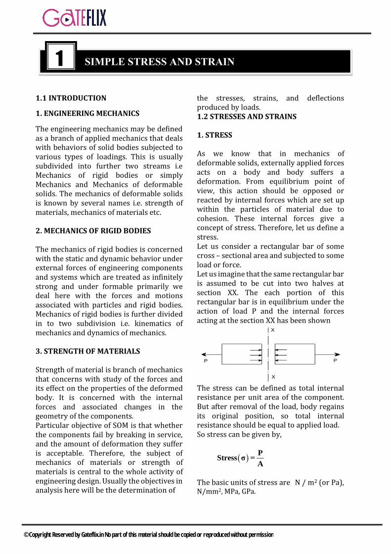
As we know that in mechanics of deformable solids, externally applied forces acts on a body and body suffers a deformation. From equilibrium point of view, this action should be opposed or reacted by internal forces which are set up within the particles of material due to cohesion. These internal forces give a concept of stress. Therefore, let us define a stress. Let us consider a rectangular bar of some cross – sectional area and subjected to some load or force. Let us imagine that the same rectangular bar is assumed to be cut into two halves at section XX. The each portion of this rectangular bar is in equilibrium under the action of load P and the internal forces acting at the section XX has been shown
The stress can be defined as total internal resistance per unit area of the component. But after removal of the load, body regains its original position, so total internal resistance should be equal to applied load. So stress can be given by,
( ) PStress σ =A
The basic units of stress are N / m2 (or Pa), N/mm2, MPa, GPa.
1 SIMPLE STRESS AND STRAIN
© Copyright Reserved by Gateflix.in No part of this material should be copied or reproduced without permission
6
9
3
MPa 10 PaGPa 10 PaKPa 10 Pa
=
=
=
Some times N / mm2 units are also used, because this is an equivalent to MPa. For direct stresses, if area under consideration is original area, then it is known as Engineering stress or nominal stress or simply stress. But, if the area taken is actual area at the time of considering the stress, then stress is known as true stress.
;o
Nominal Str s = PA
es True Stress = PA
Where, Ao = Original area of specimen. A = Actual area of specimen.
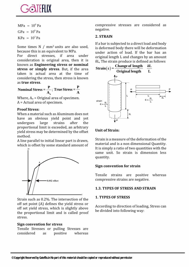
Proof Stress: When a material such as Aluminum does not have an obvious yield point and yet undergoes large strains after the proportional limit is exceeded, an arbitrary yield stress may be determined by the offset method. A line parallel to initial linear part is drawn, which is offset by some standard amount of
Strain such as 0.2%. The intersection of the off set point (A) defines the yield stress or off set yield stress, which is slightly above the proportional limit and is called proof stress.
Sign convention for stress Tensile Stresses or pulling Stresses are considered as positive whereas
compressive stresses are considered as negative.
2. STRAIN
If a bar is subjected to a direct load and body is deformed body there will be deformation under action of load. If the bar has an original length L and changes by an amount δL, The strain produce is defined as follows
( ) Change of length δLStrain ε = =Original length L
Unit of Strain: Strain is a measure of the deformation of the material and is a non dimensional Quantity. It is simply a ratio of two quantities with the same unit. So strain is dimension less quantity. Sign convention for strain Tensile strains are positive whereas compressive strains are negative.
1.3. TYPES OF STRESS AND STRAIN 1. TYPES OF STRESS According to direction of loading, Stress can be divided into following way:
© Copyright Reserved by Gateflix.in No part of this material should be copied or reproduced without permission

Normal stress (σ ) We have defined stress as force per unit area. If the stresses are normal to the areas concerned, then these are termed as normal stresses. The normal stresses are generally denoted by a Greek letter ( σ ).
Tensile or compressive stresses
The normal stresses can be either tensile or compressive whether the stresses act out of the area or into the area.
Axial Stress ( )aσ Stress produced due to load acting along the axis of the component is called as axial stress. It may be tensile or compressive in nature.
Axial Stress = o
PA
Where, Ao = Original area of specimen Bending Stress ( )bσ
Stress produced due to load in the form of bending moment or eccentric axial load is known as bending stress. Nature of bending stress is tensile and compressive. Shear stress ( )τ
Let us consider now the situation, where the cross – sectional area of a block of material is subject to a distribution of forces which are parallel, rather than normal, to the area concerned.
Such forces are associated with a shearing of the material, and are referred to as shear forces. The resulting force per unit area is known as shear stress. The resulting force intensities are known as shear stresses, the mean shear stress is given by
PShear Stress τ =A
Where P is the total force and A the area over which it acts.
2. TYPES OF STRAIN
According to basis of the deformation, strain can be classified as
© Copyright Reserved by Gateflix.in No part of this material should be copied or reproduced without permission

Normal Strain ( )ε
Deformation produced under the action of the load in the direction of the load is called as linear or normal strain. In normal strain, dimension of the body changes but the shape of the body remains same. Longitudinal Strain The linear deformation in the direction of the load is known as the longitudinal deformation. It may be tensile and compressive in nature depend upon the nature of the loading.
( )x
Change of length δLLongitudinal Strain ε = =Original length L
Lateral Strain The linear deformation in perpendicular direction of the load is known as the lateral deformation. It may be tensile and compressive in nature depend upon the nature of the longitudinal Strain.
( )yChange of diameter δDLateral Strain ε = = -Original diameter D
Volumetric Strain It is the ratio of total change of the volume to the original volume of the component.
( ) −vChange of volumeVolumetric Strain ε =Original volume
vdVε = -V
Every longitudinal strain is associated with two lateral strains.
Longitudinal strain and lateral strain are opposite in nature.
Shear strain:
When a body is subjected to shearing stresses, the shape of the body gets distorted. The measurement of this distortion is done by angle of distortion. Under pure shear the shape of the body gets distorted but the volume remains same.
( ) sheaModu r strlus of r ess=shear s
igtr
idity, Gain
G τ=γ
As we know that the shear stresses acts along the surface. The action of the Stress is to produce or being about the deformation in the body considers the distortion produced shear strain on an element or rectangular block.
If under the shear, the shear strain is γ then the linear strain in the diagonal of the specimen is given by.
d i.e.2γ
ε = Linear strain of diagonal is half of
the shear strain in the body. 3. STRAIN FOR DIFFERENT CROSS SECTIONS a) Rectangular Co- ordinates Let us consider a rectangular block of length L, width D and thickness t. after application of load P in x direction change in dimension is dL, dD and dt respectively. The strain produced in x- direction is given by
( )xChange of length dLε = =Original length L
The strain produced in y- direction is given by
( )yChange of width dWε = =Original width W
The strain produced in z- direction is given by
© Copyright Reserved by Gateflix.in No part of this material should be copied or reproduced without permission

( )zChange of thickness dtε = =Original thickness t
The volume of the rectangular body is given by V = Lwt Taking the log in both sides and differentiating the equation, volumetric strain
VdV dL dw dtεV L w t
= = + +
V x y zε = ε + +ε ε b) Cylindrical co-ordinates Let us consider a cylinder of length L, diameter. After application of load P in x direction change in dimension is dL, dD respectively. The strain produced in x and y- direction is given by
( )xChange of length dLεOriginal length L
= =
( )rChange of diameter dDεOriginal diameter D
= =
Volume of the cylinder is given by 2πV D L
4=
Taking the log in both sides and differentiating, we get volumetric strain
V l cdV dL dDε = = + 2 = ε + 2εV L D
c) Spherical co-ordinates Let us consider a sphere of diameter D. After application of load P in x direction change in diameter is dD respectively. Volumetric strain produced in spherical body is given by
V cdV dDε 3 3V D
= = = ε
1.4 HOOK’S LAW & ELASTIC PROPERTY 1. HOOKE’S LAW A material is said to be elastic if it returns to its original, unloaded dimensions when load
is removed. According to Hook’s law, Up to proportional limit stress is directly proportional to strain. Stress strain∝ Stress Const. EStrain
= =
This constant is given by the symbol E and is termed as the modulus of elasticity or
Young's modulus of elasticity σE=ε
The unit of modulus of elasticity is MPa.
Curve 1 represents actual or true stress
strain diagram. Curve 2 represents theoretical stress
strain diagram. Hooke`s law is valid up to limit of
proportionality. However for mild steel, Proportional limit and Elastic limit are almost equal, but for other metals & materials elastic limit may be higher than proportional limit, for example-Rubber.
1.5 True stress and True Strain
1. True stress: The true stress is defined as the ratio of the load to the cross section area at any instant
( ) ( )Tloadσ = = σ 1+ ε
Instantaneous area
Where σ and ε is the engineering stress and engineering strain respectively.
© Copyright Reserved by Gateflix.in No part of this material should be copied or reproduced without permission
2. True Strain:
( ) ( )
( )
∫o
L
T0L
0 0T
dl Lε = = ln = ln 1+εl L
A dε = ln =2lnA d
OR engineering strain ( ) Tεε = e -1
The volume of the specimen is assumed to be constant during plastic deformation
0 0A L =AL Q .It is valid till the neck
formation.
Where, &oA A are original & final area
respectively. &oL L are original & final length
respectively.
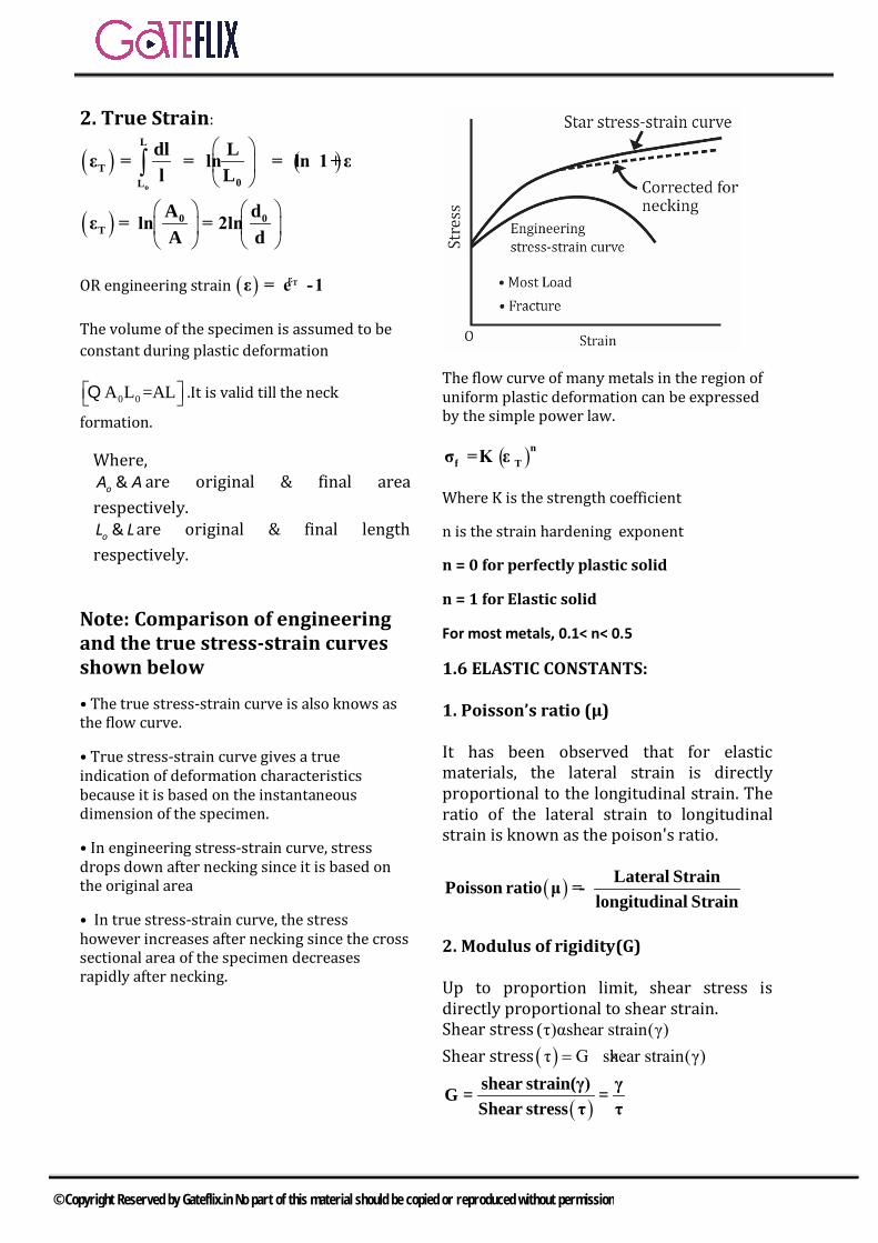
Note: Comparison of engineering and the true stress-strain curves shown below
• The true stress-strain curve is also knows as the flow curve.
• True stress-strain curve gives a true indication of deformation characteristics because it is based on the instantaneous dimension of the specimen.
• In engineering stress-strain curve, stress drops down after necking since it is based on the original area
• In true stress-strain curve, the stress however increases after necking since the cross sectional area of the specimen decreases rapidly after necking.
The flow curve of many metals in the region of uniform plastic deformation can be expressed by the simple power law.
( )nf Tσ = K ε
Where K is the strength coefficient
n is the strain hardening exponent
n = 0 for perfectly plastic solid
n = 1 for Elastic solid
For most metals, 0.1< n< 0.5
1.6 ELASTIC CONSTANTS: 1. Poisson’s ratio (μ) It has been observed that for elastic materials, the lateral strain is directly proportional to the longitudinal strain. The ratio of the lateral strain to longitudinal strain is known as the poison's ratio.
( ) Lateral StrainPoisson ratio μ = -longitudinal Strain
2. Modulus of rigidity(G) Up to proportion limit, shear stress is directly proportional to shear strain. Shear stress (τ)αshear strain(γ) Shear stress ( )τ G shear strain(γ)= ×
( )shear strain(γ) γG = =Shear stress τ τ
© Copyright Reserved by Gateflix.in No part of this material should be copied or reproduced without permission

G is known as shear modulus and its unit is same as the unit of stress i.e. MPa. 3. Bulk Modulus(K) Up to proportional limit, the hydrostatic stress is directly proportional to volumetric strain.
dVdPV
∝ −
dPK= - dVV
K is known as bulk modulus and its unit is MPa. Note: RELATIONSHIP BETWEEN ELASTIC CONSTANTS
Linear stressYoung s mod ulus,ELinear strain
=
Shear stressModulus of regidity,Gshear strain
=
Direct stressBulk mod ulus,KVolumetricstrain
=
1 LateralstrainPoisson s ratio,m Linear strain
µ = = −
1E = 2G 1+ = 2G(1+μ)m
2E = 3K 1- = 3K(1- 2μ)m
9KGE =
3K + G
1 3K 2Gm 6K 2G
−µ = =
+
1.7 TYPES OF MATERIALS 1. HOMOGENEOUS MATERIAL A material is homogenous if it has the same composition throughout body. Hence the
elastic properties are the same at every point in the body. However, the properties need not to be the same in all the direction for the material to be homogenous. Isotropic materials have the same elastic properties in all the directions. Therefore, the material must be both homogenous and isotropic in order to have the lateral strains to be same at every point in a particular component. 2. ISOTROPIC MATERIAL If the response of the material is independent of the orientation of the load axis of the sample, then we say that the material is isotropic or in other words we can say that isotropy of a material is a characteristics, which gives us the information that the properties are the same in the different direction, on the other hand if the response is dependent on orientation it is known as anisotropic. 1.8 STRAIN UNDER TRI AXIAL LOADING If a rectangular block is subjected to three normal stresses σx, σy & σz on all its faces, mutually perpendicular to each other in x, y & z directions respectively as shown in fig.
Then volumetric strain of the specimen is given by
V x y Zε = ε + ε + ε
[ ]x y zv 1 2
Eσ +σ +σ
ε = − µ
1.9 AXIAL STRESS IN COMPOUND BARS
© Copyright Reserved by Gateflix.in No part of this material should be copied or reproduced without permission

Case (a):Let the axial load is applied on the free end of the member as shown in fig. Then the load shared by each member P1 =P2 = P3 = P
Deformation produced in member 1 is given by
1 11 2
1 1 1 1
Pl 4Plδ = =A E πd E
Deformation produced in member 2 is given by
2 22 2
2 2 2 2
Pl 4Plδ = =A E πd E
Deformation produced in member 1 is given by
3 33 2
3 3 3 3
Pl 4PlδA E πd E
= =
Total deformation produced in members is given by
31 2Total
1 1 2 2 3 3
PlPl PlδA E A E A E
= + +
31 2Total 2 2 2
1 1 2 2 3 3
4Pl4Pl 4Plδπd E πd E πd E
= + +
Stress produced in member 1 is given by 1
1 21 1
P 4PσA πd
= =
Stress produced in member 2 is given by 2
2 22 2
P 4PσA πd
= =
Stress produced in member 3 is given by 3
3 23 3
P 4PσA πd
= =
Case (B): Let both ends of the members are fixed as shown in the figure.
A beam is subjected under the load P at point B and it is fixed at both the ends, the deformation produced in the body is zero, so
total 1 1δ δ δ 0= + =
1 1 2 2
1 1 2 2
P l P lor 0A E A E
+ =
1 1 2 22 2
1 1 2 2
4P l 4P lor 0πd E πd E
+ =
Where P1 and P2 is the load on member 1 and member 2 respectively If the reaction at point A and B are RA and RB, then RA+ RB = P 1.10 ELONGATION OF THE TAPER BEAM UNDER AXIAL LOAD A taper beam having circular cross section is subjected under axial load P at the free and as shown in the fig.
Maximum stress produced in the taper beam is given by
1max 2
min min
P 4PσA πd
= =
Minimum stress produced in the taper beam is given by
1min 2
max max
P 4PσA πd
= =
© Copyright Reserved by Gateflix.in No part of this material should be copied or reproduced without permission

Elongation of the taper beam at the free end
is given by total1 2
4Plδπd d E
=
Where E is modulus of elasticity d1, d2 are the diameters of the smallest and biggest end of the beam and l is the length of the beam. 1.11. ELONGATION DUE TO SELF WEIGHT OF THE BODY 1. For bar of uniform section: Due to self weight of the component, the
deformation produced in the component is given by
2L WLL
2E 2AEλ
∆ = =
Where ,g Unit weight of the material.λ = ρ = −
L = Length of the specimen E = Modulus of Elasticity of the
component W = Total self weight of specimen
A = Cross-sectional area. Thus, the deformation of the bar under
its own weight is half the deformation, if the body is subjected to the direct load equal to the weight of the body.
2. For bar of tapering section: due to self
weight of the component, the deformation produced in the component is given by
2L WLL
6E 6AEλ
∆ = =
Thus, the deformation of taper bar under its own weight is one third of the
deformation in uniform cross section under its self weight.
1.12 THERMAL STRESS
If temperature of the component is increased or decreased, thermal expansion or contraction in the component takes place. If this thermal expansion or contraction is restricted either completely or partially, then thermal stress produces in the component. The stress produced due to thermal expansion or contraction is called as thermal stress. If there is free thermal expansion and
contraction or it is not resisted by any Resistance then thermal stress is zero.
1. FREE EXPANSION When beam is supported at one end and its other end is free, temperature increase ΔT, due to this temperature difference change in length of the beam is ΔL. If thermal expansion co-efficient of the material of the beam is α, Free expansion in length is given by
ΔL = α L ΔT Stress produced in the member is given by
thermalσ 0= 2. WHEN ENDS OF THE COMPOSITE BAR ARE RESTRICTED If the free expansion or contraction is prevented then stresses will be developed
© Copyright Reserved by Gateflix.in No part of this material should be copied or reproduced without permission
Let us consider the separate effect of the temperature and the reaction at the fixed reactions.
Thermal expansion in the body is given by ΔL = α L ΔT Axial compression in the member due to reaction in the beam is given by ΔLa =-α L ΔT Thermal stress produced in the member is given by thermal Eσ T= α ∆− If temperature of the component is
increased the thermal stress produced in the member is compressive and vice versa.
3. WHEN ENDS OF THE COMPOSITE BAR ARE RESTRICTED PARTIALLY If partial elongation is allowed, thermal stress produced in the component
thermalαLΔT δσ E
L− =
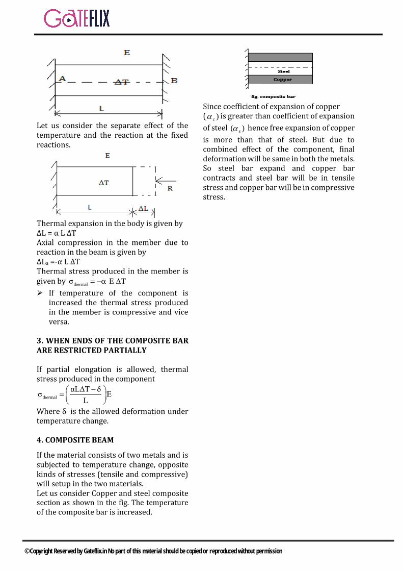
Where δ is the allowed deformation under temperature change. 4. COMPOSITE BEAM
If the material consists of two metals and is subjected to temperature change, opposite kinds of stresses (tensile and compressive) will setup in the two materials. Let us consider Copper and steel composite section as shown in the fig. The temperature of the composite bar is increased.
Since coefficient of expansion of copper ( )cα is greater than coefficient of expansion of steel )( sα hence free expansion of copper is more than that of steel. But due to combined effect of the component, final deformation will be same in both the metals. So steel bar expand and copper bar contracts and steel bar will be in tensile stress and copper bar will be in compressive stress.
© Copyright Reserved by Gateflix.in No part of this material should be copied or reproduced without permission
Q.1 Two identical circular rods of same diameter and same length are subjected to same magnitude of axial tensile force. One of the rod is made out of mild steel having the modulus of elasticity of 206 GPa. The other rod is made out of cast iron having the modulus of elasticity of 100 GPa. Assume both the materials to be homogeneous and isotropic and the axial force causes the same amount of uniform stress in both the rods. The stresses developed are within the proportional limit of the respective materials. Which of the following observations is correct? a) Both rods elongate by the same
amount b) Mild steel rod elongates more
than the cast iron rod c) Cast iron rod elongates more
than the mild steel rods d) As the stresses are equal strains
are also equal in both the rods [GATE-2003]
Q.2 The figure below shows a steel rod of 25 mm2 cross sectional area. It is loaded at four points, K, L, M and N. Assume Esteel =200 GPa. The total change in length of the rod due to loading is
a) 1 µm b) −10 µmc) 16 µm d) −20 µm
[GATE-2004]
Q.3 A steel bar of 40mm×40 mm square cross-section is subjected to an
axial compressive load of 200 kN. If the length of the bar is 2m and E=200 GPa, the contraction of the bar will be a) 1.25 mm b) 2.70 mmc) 4.05 mm d) 5.40 mm
[GATE-2006]
Q.4 A bar having a cross-sectional area of 700 mm2 is subjected to axial loads at the positions indicated. The value of stress in the segment QR is
a) 40 MPa b) 50 MPac) 70 MPa d) 120 MPa
[GATE-2006]
Q.5 A 200×100×50 mm steel block is subjected to a hydrostatic pressure of 15 MPa. The Young's modulus and Poisson's ratio of the material are 200 GPa and 0.3 respectively. The change in the volume of the block in mm3 is a) 85 b) 90c) 100 d) 110
[GATE-2007]
Q.6 A rod of length L and diameter D is subjected to a tensile load P. Which of the following is sufficient to calculate the resulting change in diameter? a) Young’s modulusb) Shear modulusc) Poisson’s ratiod) Both Young’s modulus and shear
modulus [GATE-2008]
Common Data For Q. 7 and 8:
GATE QUESTIONS
© Copyright Reserved by Gateflix.in No part of this material should be copied or reproduced without permission

A cylindrical container of radius R = 1 m, wall thickness 1 mm is filled with water up to a depth of 2 m and suspended along its upper rim. The density of water is 1000 kg/m3 and acceleration due to gravity is 10 m/s2. The self-weight of the cylinder is negligible. The formula for hoop stress in a thin-walled cylinder can be used at all points along the height of the cylindrical container.
Q.7 The axial and circumference stress
(σa,σc) experienced by the cylinder wall at mid-depth (1m as shown) are a) (10, 10)MPa b) (5,10)MPa c) (10, 5)MPa d) (5, 5)MPa [GATE-2008]
Q.8 If the Young's modulus and
Poisson's ratio of the container material are 100 GPa and 0.3, respectively, the axial strain in the cylinder wall at mid-depth is
a) 52 10−× b) 56 10−× c) 57 10−× d) 41.2 10−×
[GATE-2008] Q.9 A rod of length L having uniform
cross-sectional area A is subjected to a tensile force P as shown in the figure below. If the Young’s modulus of the material varies linearly from E1 to E2 along the length of the rod, the normal stress developed at the section-SS is
a) PA
b) 1 2
1 2
P(E E )A(E E )
−+
c) 2
1
PEAE
d) 1
2
PEPE
[GATE-2013] Q.10 A circular rod of length ‘L’ and area
of cross-section ‘A’ has a modulus of elasticity ‘E’ and coefficient of thermal expansion ‘α’. One end of the rod is fixed and other end is free. If the temperature of the rod is increased by ∆T, then a) stress developed in the rod is E α
∆T and strain developed in the rod is α ∆T
b) both stress and strain developed in the rod are zero.
c) stress developed in the rod is zero and strain developed in the rod is α ∆T
d) stress developed in the rod is EαΔT and strain developed in the rod is zero
[GATE-2014 (1)] Q.11 The stress-strain curve for mild
steel is shown in figure given below. Choose the correct option referring to both figure and table.
Point on the
graph Description of the point
P. 1. Upper yield point Q. 2. Ultimate Tensile strength R. 3. Proportionality limit S. 4. Elastic limit T. 5. Lower yield point U. 6. Failure
© Copyright Reserved by Gateflix.in No part of this material should be copied or reproduced without permission
a) P-1, Q-2, R-3, S-4, T-5, U-6 b) P-3,Q-1,R-4,S-2,T-6,U-5 c) P-3, Q-4, R-1, S-5, T-2, U-6 d) P-4, Q-1, R-5, S-2,T-3,U-6
[GATE-2014(3)] Q.12 Which one of the following types of
stress- strain relationship best describes the behavior of brittle materials, such as ceramics and thermosetting plastics, (σ = stress and ε = strain)? a) b)
c) d)
[GATE-2015 (1)]
Q.13 A horizontal bar with a constant
cross-section is subjected to loading as shown in the figure. The Young’s modul i for the sections AB and BC are 3E and E, respectively.
For the deflection at C to be zero, the ratio P/F is ____________
[GATE-2016 (1)] Q.14 A circular metallic rod of length 250
mm is placed between two rigid immovable walls as shown in the figure. The rod is in perfect contact with the wall on the left side and there is a gap of 0.2 mm between the rod and the wall on the right side. If the temperature of the rod is increased by 200℃, the axial stress
developed in the rod is __________ MPa. Young’s modulus of the material of the rod is 200 GPa and the coefficient of thermal expansion is 10−5 per oC.
[GATE-2016 (2)]
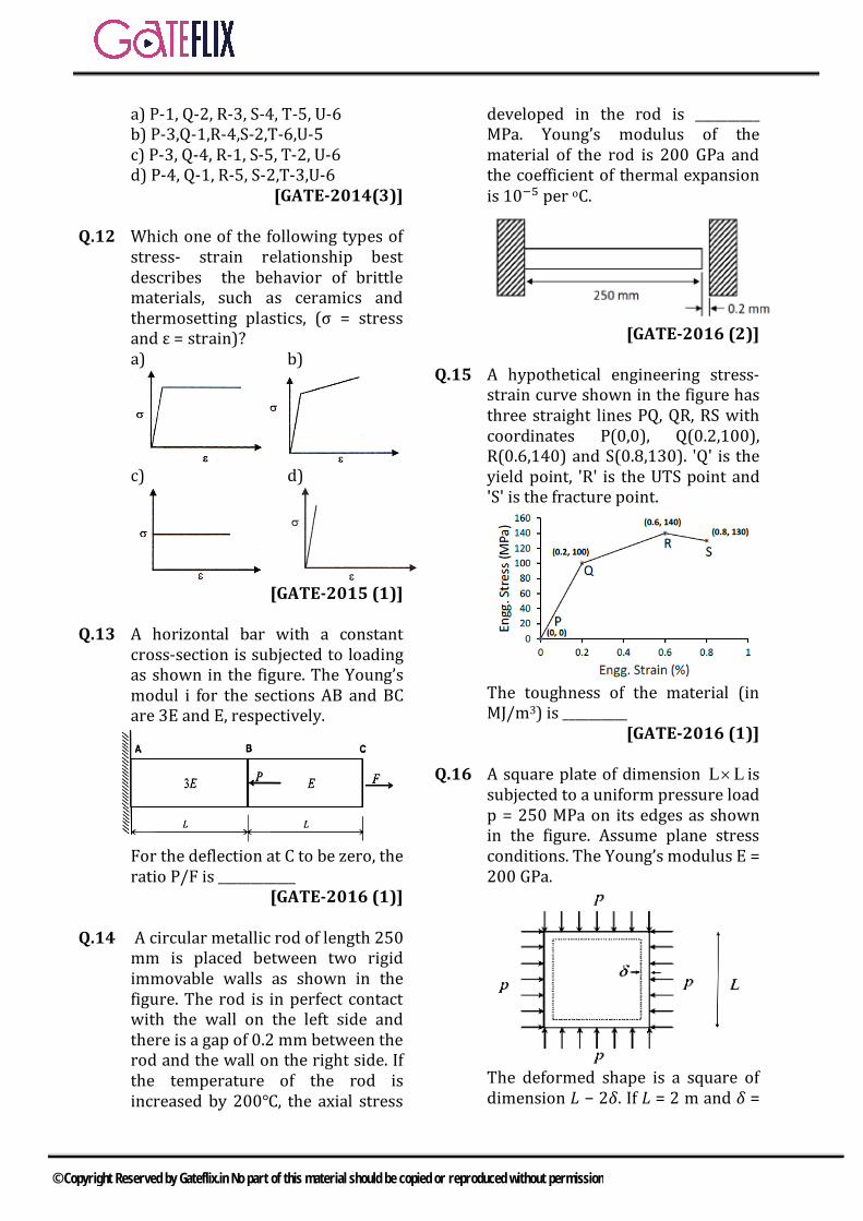
Q.15 A hypothetical engineering stress-
strain curve shown in the figure has three straight lines PQ, QR, RS with coordinates P(0,0), Q(0.2,100), R(0.6,140) and S(0.8,130). 'Q' is the yield point, 'R' is the UTS point and 'S' is the fracture point.
The toughness of the material (in MJ/m3) is __________
[GATE-2016 (1)] Q.16 A square plate of dimension L L× is
subjected to a uniform pressure load p = 250 MPa on its edges as shown in the figure. Assume plane stress conditions. The Young’s modulus E = 200 GPa.
The deformed shape is a square of dimension 𝐿𝐿 − 2𝛿𝛿. If 𝐿𝐿 = 2 m and 𝛿𝛿 =
© Copyright Reserved by Gateflix.in No part of this material should be copied or reproduced without permission
0.001 m, the Poisson’s ratio of the plate material is __________
[GATE-2016 (3)] Q.17 The state of stress at a point 0x y z xz zx yz zyσ σ σ τ τ τ τ= = = = = = =
and 50 MPaxy yxτ τ= = . The maximum normal stress (in MPa) at that point is _________ [GATE-2017 (2)] Q.18 In the engineering stress-strain curve for mild steel, the Ultimate Tensile Strength (UTS) refers to
[GATE-2017 (1)] (A) Yield stress (B) Proportional limit (C) Maximum stress
(D) Fracture stress.
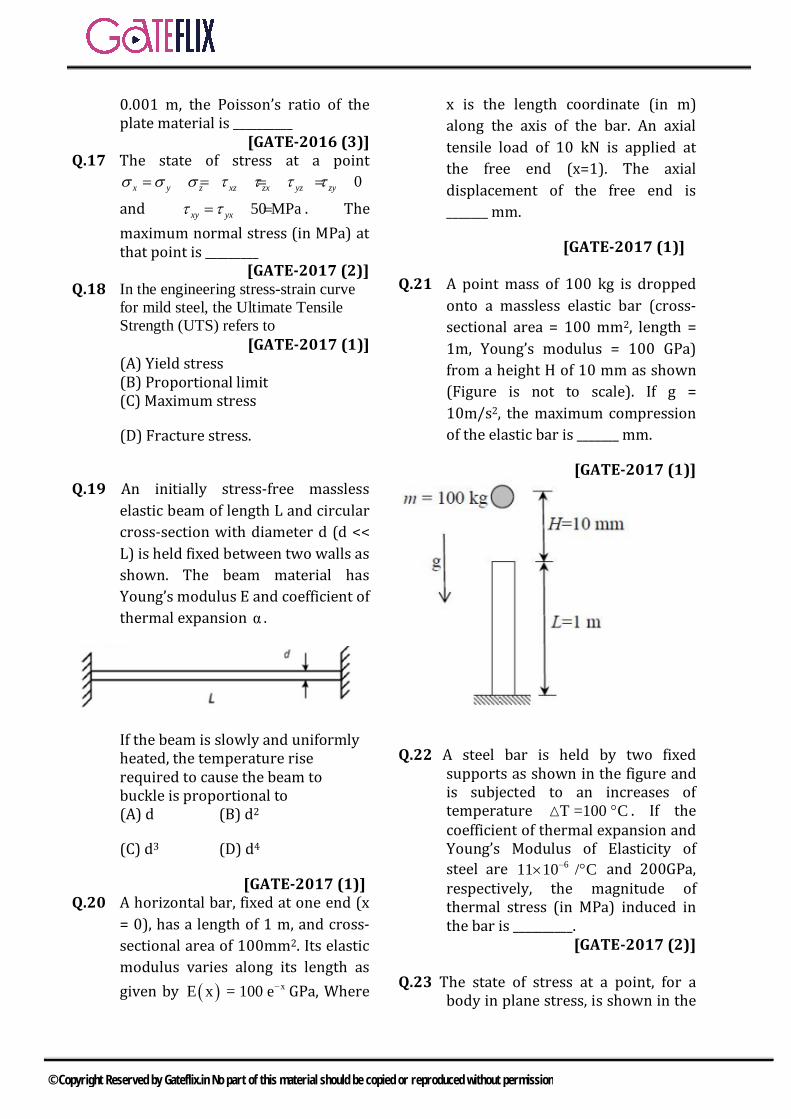
Q.19 An initially stress-free massless elastic beam of length L and circular cross-section with diameter d (d << L) is held fixed between two walls as shown. The beam material has Young’s modulus E and coefficient of thermal expansion α .
If the beam is slowly and uniformly heated, the temperature rise required to cause the beam to buckle is proportional to (A) d (B) d2
(C) d3 (D) d4
[GATE-2017 (1)] Q.20 A horizontal bar, fixed at one end (x = 0), has a length of 1 m, and cross- sectional area of 100mm2. Its elastic modulus varies along its length as given by ( ) xE x = 100 e− GPa, Where
x is the length coordinate (in m) along the axis of the bar. An axial tensile load of 10 kN is applied at the free end (x=1). The axial displacement of the free end is _______ mm.
[GATE-2017 (1)] Q.21 A point mass of 100 kg is dropped onto a massless elastic bar (cross- sectional area = 100 mm2, length = 1m, Young’s modulus = 100 GPa) from a height H of 10 mm as shown (Figure is not to scale). If g = 10m/s2, the maximum compression of the elastic bar is _______ mm.
[GATE-2017 (1)]
Q.22 A steel bar is held by two fixed supports as shown in the figure and is subjected to an increases of temperature T =100 C° . If the coefficient of thermal expansion and Young’s Modulus of Elasticity of steel are 611 10 / C−× ° and 200GPa, respectively, the magnitude of thermal stress (in MPa) induced in the bar is __________.
[GATE-2017 (2)]
Q.23 The state of stress at a point, for a body in plane stress, is shown in the
© Copyright Reserved by Gateflix.in No part of this material should be copied or reproduced without permission
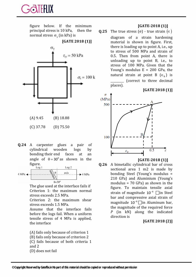
figure below. If the minimum principal stress is 10 kPa, then the normal stress yσ (in kPa) is
[GATE 2018 (1)]
(A) 9.45 (B) 18.88
(C) 37.78 (D) 75.50
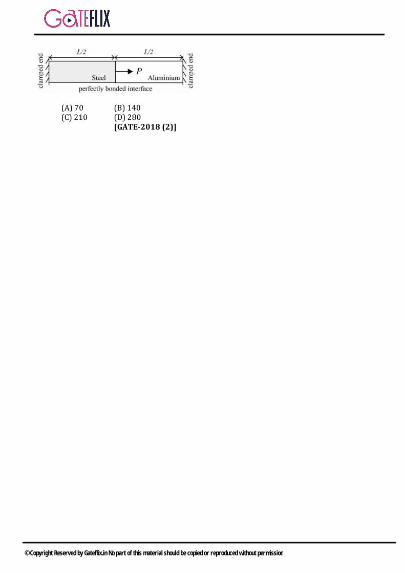
Q.24 A carpenter glues a pair of cylindrical wooden logs by bonding their end faces at an angle of 030θ = as shown in the figure.
The glue used at the interface fails if Criterion 1: the maximum normal stress exceeds 2.5 MPa. Criterion 2: the maximum shear stress exceeds 1.5 MPa. Assume that the interface fails before the logs fail. When a uniform tensile stress of 4 MPa is applied, the interface (A) fails only because of criterion 1 (B) fails only because of criterion 2 (C) fails because of both criteria 1 and 2 (D) does not fail
[GATE-2018 (1)] Q.25 The true stress (σ) - true strain ( )∈ diagram of a strain hardening material is shown in figure. First, there is loading up to point A, i.e., up to stress of 500 MPa and strain of 0.5. Then from point A, there is unloading up to point B, i.e., to stress of 100 MPa. Given that the Young’s modulus E = 200 GPa, the natural strain at point B ( B∈ ) is _________ (correct to three decimal places).
[GATE 2018 (1)]
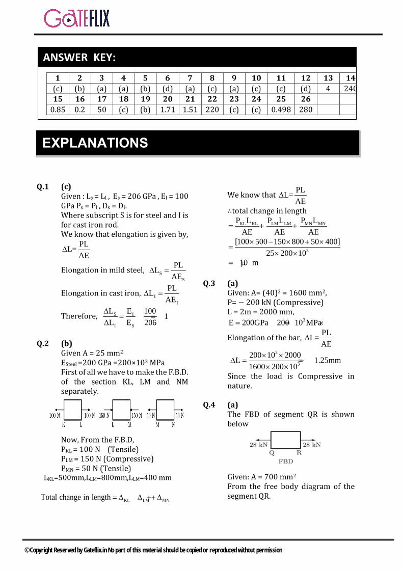
[GATE-2018 (1)] Q.26 A bimetallic cylindrical bar of cross sectional area 1 m2 is made by bonding Steel (Young’s modulus = 210 GPa) and Aluminium (Young’s modulus = 70 GPa) as shown in the figure. To maintain tensile axial strain of magnitude 610− in Steel bar and compressive axial strain of magnitude 610− in Aluminum bar, the magnitude of the required force P (in kN) along the indicated direction is
[GATE 2018 (2)]
© Copyright Reserved by Gateflix.in No part of this material should be copied or reproduced without permission
(A) 70 (B) 140 (C) 210 (D) 280 [GATE-2018 (2)]
© Copyright Reserved by Gateflix.in No part of this material should be copied or reproduced without permission
Q.1 (c) Given : Ls = LI , Es = 206 GPa , EI = 100 GPa Ps = PI , Ds = DI. Where subscript S is for steel and I is for cast iron rod. We know that elongation is given by,
PLL=AE
∆
Elongation in mild steel, SS
PLLAE
=∆
Elongation in cast iron, II
PLLAE
=∆
Therefore, S I
I S
L E 100 1L E 206
∆= = <
∆
Q.2 (b) Given A = 25 mm2 ESteel =200 GPa =200×103 MPa First of all we have to make the F.B.D. of the section KL, LM and NM separately.
Now, From the F.B.D, PKL = 100 N (Tensile) PLM = 150 N (Compressive) PMN = 50 N (Tensile)
LKL=500mm,LLM=800mm,LLM=400 mm
KL LM MNTotal change in length ∆∆ + ∆= +
We know that PLL=AE
∆
∴total change in length MN MNKL KL LM LM P LP L P L
AE AE AE= + +
3
[100 500 150 800 50 400]25 200 10
× − × + ×=
× ×10 m= − µ
Q.3 (a) Given: A= (40)2 = 1600 mm2, P= − 200 kN (Compressive) L = 2m = 2000 mm,
3E 200GPa 200 10 MPa= = ×
Elongation of the bar, PLL=AE
∆
3
3
200 10 2000L 1.25mm1600 200 10
× ×∆ = = −
× ×Since the load is Compressive in nature.
Q.4 (a) The FBD of segment QR is shown below
Given: A = 700 mm2 From the free body diagram of the segment QR.
1 2 3 4 5 6 7 8 9 10 11 12 13 14 (c) (b) (a) (a) (b) (d) (a) (c) (a) (c) (c) (d) 4 240 15 16 17 18 19 20 21 22 23 24 25 26
0.85 0.2 50 (c) (b) 1.71 1.51 220 (c) (c) 0.498 280
ANSWER KEY:
EXPLANATIONS
© Copyright Reserved by Gateflix.in No part of this material should be copied or reproduced without permission

Force acting on QR=28 kN (Tensile)Stress in segment QR is given by
328 10 40MPa
700×
σ = =
Q.5 (b) We know that,
( )V 3σ 1 2μV E
∆= −
[ ]3
V 3 15 1 (2 0.3)200 100 50 200 10
∆ ×= − ×
× × ×
∴ΔV = 90 mm3
Q.6 (d)
Q.7 (a) Pressure(P)=hρg=1×1000×10=10 kPa Axial Stress ( )aσ
2aσ 2πRt ρg πR L⇒ × = ×
Or
a 3
ρgRL 1000 10 1 1σ 10MPat 1 10−
× × ×= = =
×
Circumferential Stress
( )c 3
PR 10 1σ 10MPat 1 10−
×= = =
×
Q.8 (c) a c
aσ σε μE E
= −
3 3
10 100.3100 10 100 10− −= − ×
× ×57 10−= ×
Q.9 (a)
The normal stress is given by PσA
=
We see that normal stress only depends on force and area and it does not depends on E.
Q.10 (c)
For thermal stress to be developed there must be constraint in the system. So, although strain develops but there is no thermal stress.
Q.11 (c)
P:Proportional limit Q: Elastic limit R: Upper Yield Point S: Lower Yield Point T: Ultimate Tensile Strength U: Failure /Rupture
Q.12 (d) Q.13 (4)
Cδ 0=
AB BCδ δ 0⇒ + =
[ ]P F L FL 0A(3E) AE
− −+ =
F P F 03−
+ =
4F = P
P 4F
∴ =
Q.14 (240)
( )3PLLα T 0.2 10AE
−∆ − = ×
Multiplying above equation by EL
3 EEα T σ (0.2 10 )L
−∆ − = ×
( )9
9 5 3 200 10σ 200 10 10 20 0.2 10
0.25− − ×
= × × × − × ×
6σ 240 10 Pa= × σ 240MPa=
Q.15 (0.85)
© Copyright Reserved by Gateflix.in No part of this material should be copied or reproduced without permission
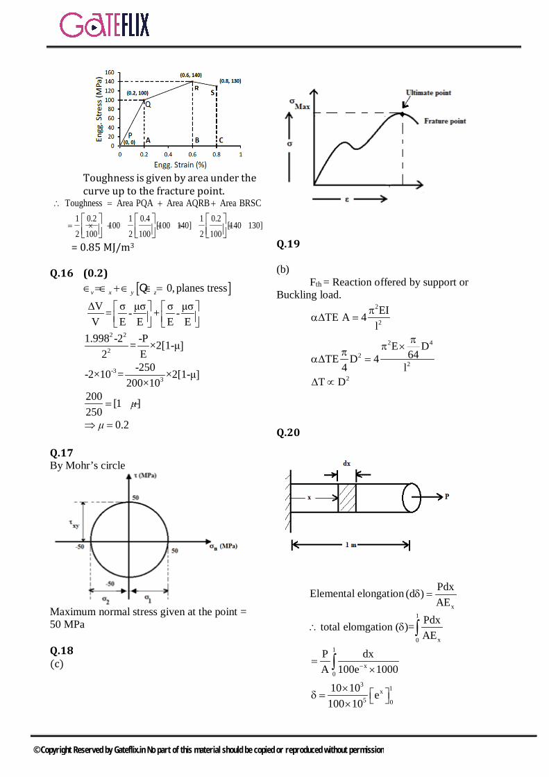
Toughness is given by area under the curve up to the fracture point.
Toughness Area PQA Area AQRB Area BRSC∴ = + + 1 0.2 1 0.4 1 0.2
100 [100 140] [140 130]2 100 2 100 2 100
= × + + + +
= 0.85 MJ/m3
Q.16 (0.2) [ ]0,planes tressv x y z∈ =∈ + ∈ ∈ =Q
V σ μσ σ μσ= - + -V E E E E
∆
2 2
2
1.998 -2 -P= ×2[1-μ]2 E
-33
-250-2×10 = ×2[1-μ]200×10
200 [1 ]250
= − μ
0.2⇒ =μ Q.17 By Mohr’s circle
Maximum normal stress given at the point = 50 MPa Q.18 (c)
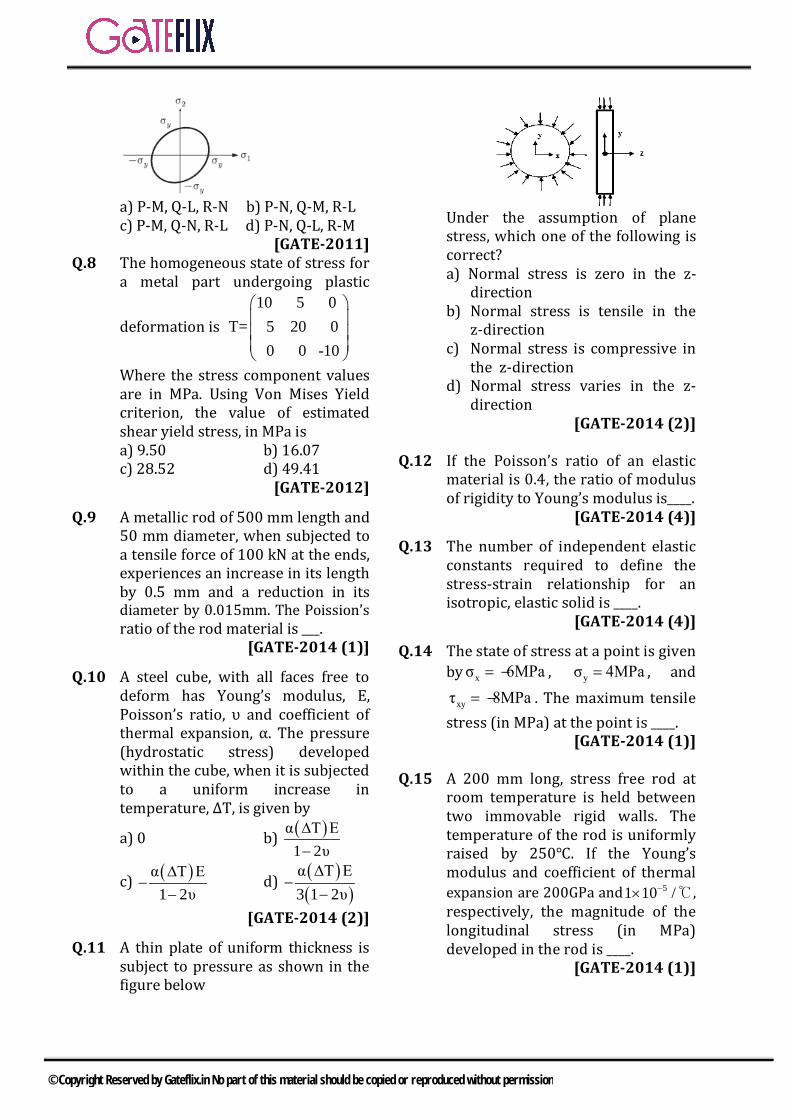
Q.19 (b) Fth = Reaction offered by support or Buckling load.
2
2
EITE A 4l
πα∆ =
2 4
22
E D64TE D 4
4 l
ππ ×π
α∆ =
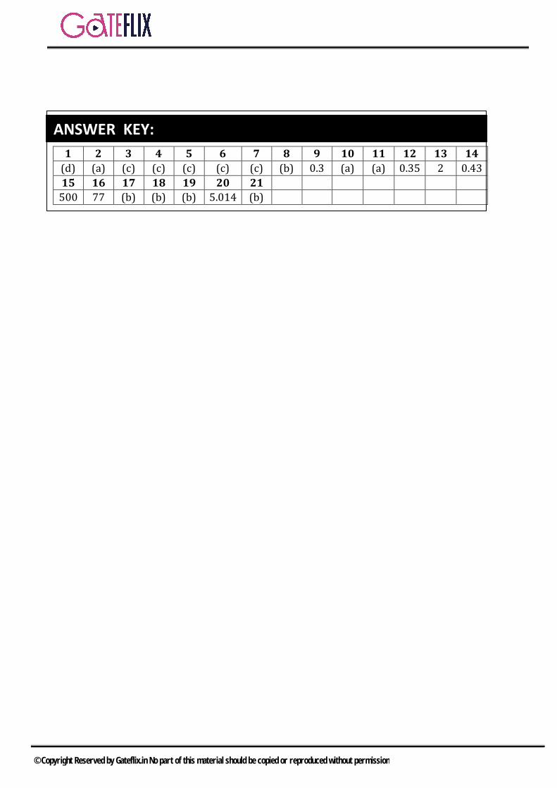
2DT∆ ∝ Q.20
Elemental elongationx
Pdx(d )AE
δ =
1
x0
Pdxtotal elomgation ( )=AE
∴ δ ∫
1
x0
P dxA 100e 1000−=
×∫
3 1x5 0
10 10 e100 10
× δ = ×
© Copyright Reserved by Gateflix.in No part of this material should be copied or reproduced without permission

3
1 [e 1]10
δ = −
1.718mmδ = Q.21 Let the compression is x meter For the conservation of energy P.E=Elastic energy
21mg[h x] kx2
+ =
Where, EAkl
=
21 EAmg[h x] x2 l
+ =
3 21 100 10 100x100 10[0.01 x]
2 1× ×
× + = ×
20.01 x 5000x+ = 25000x x 0.01 0− − =
2
1,2b b 4acx
2a− ± −
=
1,21 1 4 5000 0.01 1 14.17x
2 5000 10000± + × × ±
= =×
If take positive then
115.17x meter 1.517mm10000
= =
1x 1.517mm= Q.22 Sol: (220)
Since th t.Eσ = α∆ 6 311 10 100 200 10−= × × × ×
th 220MPaσ = Q.23
x xy
2
2xy
2
2
2
2
2
Ans. (c)100 kPa, 50 kPa
Minimum principal strees =
2 2
100 10010 50
2 2
50 50 50 102 2
402
By squaring
2500+ 504
x y x y
y y
y y
y
yy
τ
τ
= =
+ −− +
+ −= − +
∴ − + = + −
= +
− +
2
2500 1600 404
90 3400
37.78 MPa
yy
y
y
= + +
∴ =
=
Q.24(c)
2
2
o
Normal stress on inclined planeT ' cos
cos 30 3 MPa
Shear stress on inclined plane ' = sin 22
2 sin 60
x
xτ
= θ
= 4 =
θ
=
1.73 MPa
Since both the stress exceeds the given limits, So, Answer is option (c)
=
Q.25
© Copyright Reserved by Gateflix.in No part of this material should be copied or reproduced without permission

( )
( )3
3
Ans. 0.498We know thatSlope of AB lineis E
ACE =BC
500 100 MPa200 10 MPa =
BC400BC = 0.002
200 100.5 0.002 0.498E
−
=
∴ ∈ = − =
Q.26
611
1 16
1
622
2 26 9
2
1 2
P 10A E
P 10 1 210 210 kNP 10
A EP 10 1 70 10 70kN
P = P P 210 70 280 kN
−
−
−
−
∈ = =
= =
∈ = =
⇒ = =
+ = + =
© Copyright Reserved by Gateflix.in No part of this material should be copied or reproduced without permission

Q.1 A shaft subjected to torsion experiences pure shear stress τ on the surface. The maximum principal stress on the surface which is at 45° to the axis will have a value a)τ cos 45° b) 2τ cos 45°c) τ cos245° d) 2τ sin 45° cos 45°
[GATE-2003]
Q.2 In terms of Poisson's ratio (υ) the ratio of Young's Modulus (E) to Shear Modulus (G) of elastic materials is a) 2 (1 + υ) b) 2 (1 − υ)c) 1/2 (1 + υ) d) 1 /2 (1 − υ)
[GATE-2004]
Q.3 According to Von-Mises distortion energy theory, the distortion energy under three dimensional stress stage is represented by a) ( )2 2 2
1 2 3 1 2 3 2 1 31 2
2Eσ σ σ υ σ σ σ σ σ σ + + − + +
b) ( )2 2 21 2 3 1 2 3 2 1 3
1 2 26E
υ σ σ σ σ σ σ σ σ σ− + + + + +
c) ( )1 2 2 21 2 3 1 2 3 2 1 33E
υσ σ σ σ σ σ σ σ σ
++ + − + +
d) ( )2 2 21 2 3 1 2 3 2 1 3
13E
σ σ σ υ σ σ σ σ σ σ + + − + +
[GATE-2006]
Q.4 If the principal stresses in a plane stress problem are 1σ = 100 MPa, 2σ= 40 MPa, the magnitude of the maximum shear stress (in MPa) will be a) 60 b) 50c) 30 d) 20
[GATE-2010]
Q.5 A solid circular shaft of diameter d is subjected to a combined bending moment M and torque, T. The material property to be used for
designing the shaft using the
relation 2 23
16 M Tπd
+ is
a) Ultimate tensile strength (Su)b) Tensile yield strength (Sy)c) Torsional yield strength (Ssy)d) Endurance strength (Se)
[GATE-2009]
Q.6 The state of plane-stress at a point is given by σx = −200MPa, σy=100 MPa τxy = 100 MPa. The maximum shear stress (in MPa) is a) 111.8 b) 150.1c) 180.3 d) 223.6
[GATE-2010]
Q.7 Match the following criteria of material failure, under biaxial stresses σ1 and σ2 and yield stress σy, with their corresponding graphic representations. List I P. Maximum-normal-stress criterion Q. Maximum-distortion-energy criterion R. Maximum-shear-stress criterion List II L.
M.
N.
GATE QUESTIONS
© Copyright Reserved by Gateflix.in No part of this material should be copied or reproduced without permission
a) P-M, Q-L, R-N b) P-N, Q-M, R-L
c) P-M, Q-N, R-L d) P-N, Q-L, R-M [GATE-2011]
Q.8 The homogeneous state of stress for a metal part undergoing plastic
deformation is 10 5 0
T= 5 20 0 0 0 -10
Where the stress component values are in MPa. Using Von Mises Yield criterion, the value of estimated shear yield stress, in MPa is
a) 9.50 b) 16.07 c) 28.52 d) 49.41
[GATE-2012]
Q.9 A metallic rod of 500 mm length and 50 mm diameter, when subjected to a tensile force of 100 kN at the ends, experiences an increase in its length by 0.5 mm and a reduction in its diameter by 0.015mm. The Poission’s ratio of the rod material is ___.
[GATE-2014 (1)]
Q.10 A steel cube, with all faces free to deform has Young’s modulus, E, Poisson’s ratio, υ and coefficient of thermal expansion, α. The pressure (hydrostatic stress) developed within the cube, when it is subjected to a uniform increase in temperature, ∆T, is given by
a) 0 b) ( )α T E1 2υ
∆−
c) ( )α T E1 2υ
∆−
− d) ( )
( )α T E3 1 2υ
∆−
−
[GATE-2014 (2)]
Q.11 A thin plate of uniform thickness is subject to pressure as shown in the figure below
Under the assumption of plane stress, which one of the following is correct? a) Normal stress is zero in the z-
direction b) Normal stress is tensile in the
z-direction c) Normal stress is compressive in
the z-direction d) Normal stress varies in the z-
direction [GATE-2014 (2)]
Q.12 If the Poisson’s ratio of an elastic
material is 0.4, the ratio of modulus of rigidity to Young’s modulus is____.
[GATE-2014 (4)]
Q.13 The number of independent elastic constants required to define the stress-strain relationship for an isotropic, elastic solid is ____.
[GATE-2014 (4)]
Q.14 The state of stress at a point is given by xσ 6MPa= − , yσ 4MPa= , and
xyτ 8MPa= − . The maximum tensile stress (in MPa) at the point is ____.
[GATE-2014 (1)]
Q.15 A 200 mm long, stress free rod at room temperature is held between two immovable rigid walls. The temperature of the rod is uniformly raised by 250℃. If the Young’s modulus and coefficient of thermal expansion are 200GPa and 51 10 /−× ℃, respectively, the magnitude of the longitudinal stress (in MPa) developed in the rod is ____.
[GATE-2014 (1)]
© Copyright Reserved by Gateflix.in No part of this material should be copied or reproduced without permission

Q.16 A rod is subjected to a uni-axial load within linear elastic limit. When the change in the stress is 200 MPa, the change in the strain is 0.001, If the Possion’s ratio of the rod is 0.3, the modulus of rigidity (in GPa) is ____
[GATE-2015 (2)]
Q.17 A shaft with a circular cross-section is subjected to pure twisting moment. The ratio of the maximum shear stress to the largest principal stress is a) 2.0 b) 1.0 c) 0.5 d) 0
[GATE-2016 (2)] Q.18 The state of stress at a point on an
element is shown in figure (a). The same state of stress is shown in another coordinate system in figure (b).
The components xx yy xy(τ , τ , τ ) are given by
a) (P / 2, P / 2,0)− b) (0 , 0 , P) c) (P, P, P / 2) − d) (0,0,P / 2)
[GATE-2016 (3)]
Q.19 The Poisson’s ratio for a perfectly incompressible linear elastic material is
(A) 1 (B) 0.5
(C) 0 (D) infinity
[GATE-2017 (1)]
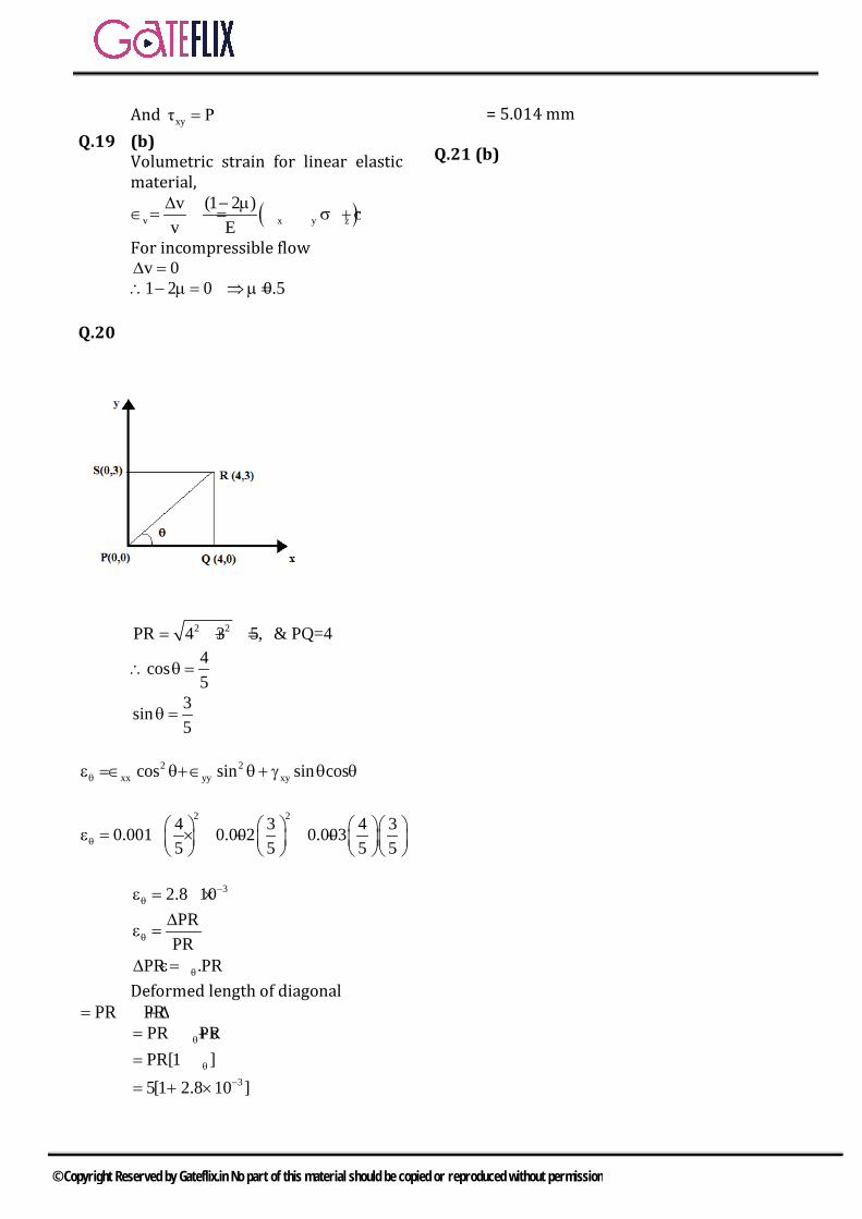
Q.20 A rectangular region in a solid is in a state of plane strain. The (x,y) coordinates of the corners of the
under deformed rectangle are given by P(0,0), Q (4,0), S (0,3). The rectangle is subjected to uniform strains, ε 0.001,ε 0.002, 0.003xx yy xyγ= = = .
The deformed length of the elongated diagonal, up to three decimal places, is _________ units.
[GATE-2017 (1)]
Q.21 If 1σ and 3σ are the algebraically largest and smallest principal stresses respectively, the value of the maximum shear stress is
(A) 1 3
2+ (B) 1 3
2−
(C) 1 3
2+
(D) 1 3
2−
[GATE-2018 (1)]
© Copyright Reserved by Gateflix.in No part of this material should be copied or reproduced without permission
1 2 3 4 5 6 7 8 9 10 11 12 13 14 (d) (a) (c) (c) (c) (c) (c) (b) 0.3 (a) (a) 0.35 2 0.43 15 16 17 18 19 20 21
500 77 (b) (b) (b) 5.014 (b)
ANSWER KEY:
© Copyright Reserved by Gateflix.in No part of this material should be copied or reproduced without permission
Q.1 (d) 2
x y x y 21/2 xy
σ σ σ σσ τ
2 2+ −
= ± +
For pure shear, xσ 0= and yσ 0= and xyτ τ=
21/2σ 0 τ⇒ = ±
1/2σ τ= ±∴ maximum principal stress = τ It can be written as 2τ sin 45° cos 45°
1 12
22
×= ×τ× = τ
Q.2 (a) Relation between, E G and u is given by,
( )E 2G 1 υ= +Where E = Young’s modulus G = Shear Modulus υ = Poisson’s ratio
Now, E 2( )1G= + υ
Q.3 (c)
Q.4 (c) Given = 21 100MPa, 4σ Paσ 0M= =We know, the maximum shear stress for the plane complex stress is given by
1 2max
σ σ 100 40τ 30MPa2 2− −
= ==
Q.5 (c)
We know that, for a shaft subjected to combined bending moment M and torque T, the equivalent Torque is,
2 2eT M T= +
Induced shear stress is, 2 2
3
16 M Tπd
+τ =
Now, for safe design, should be
less then SYSN
Where Ssy = Torsional yield strength and N = Factor of safety.
Q.6 (c)
Q.7 (c) So correct pairs are, P-M, Q-N, R-L
Q.8 (b) x y xy zσ 10,σ 20, τ 5,σ 10= = = = −
2x y x y 2
1,2 xy
σ σ σ σσ τ
2 2+ −
= ± +
1σ 15 25 25= + +
1σ 22.07MPa=
2σ 7.928MPa=
3 zσ σ 10= = −
ytσ = yield stress in tension
ysσ = yield stress in shear According to Von mises theory
( ) ( )( ) ( )
22 1 2
yt 2 22 3 3 1
σ σ1σ2 σ σ σ σ
− ≥ + − + −
( )2
ytσ 772.435≥
ytσ 27.79≥
Now ytys
σσ
3=
EXPLANATIONS
© Copyright Reserved by Gateflix.in No part of this material should be copied or reproduced without permission

ysσ 16.046MPa∴ = Q.9 (0.3)
Lateral strainµLongitudinal strain
= −
DDL
L
∆ = −∆
L DD L
∆ µ = − ∆
Given , L = 500mm, D = 50mm, ∆D = - 0.015, ∆L = +0.5mm
500 0.015µ 0.350 0.500
∴ = × =
Q.10 (a)
As all faces are free to deform, there are no thermal stresses.
Q.11 (a)
Thin plate of uniform thickness pertains to plane stress condition. So, stress out of plane would be zero.
Q.12 (0.357)
E = 2G (1 + µ)
G 1 1 1E 2(1 µ) 2 1.4 2.8= = =
+ ×
0.357= Q.13 (2)
Either E or G, 2 independent constant Either G or K, 2 independent constant Either E or K, 2 independent constant
Q.14 (8.43)
2x y x y 2
1 xy
σ σ σ σσ τ
2 2+ −
= + +
2
26 4 6 4 ( 8)2 2
− + − + = + + −
1 25 64= − + + 1 89 8.4339MPa= − + = Q.15 (500)
Given, L = 200 mm ∆T = 250°C
51 10 /−α = × ℃ E = 200 GPa σ = ? σ = α ∆TE
5 310 250 200 10−= × × × = 500 MPa
Q.16 (77)
Modulus of rigidity (G) E
2( μG
1 )=
+
It has given change in stress=200 MPa Change in strain = 0.001 Here, 200 = E × 0.001
3200MPaE 200 10 MPa0.001
⇒ = == ×
= 200 GPa 200 200 100 1000G
2(1 0.3) 2 1.3 1.3 13= = = =
+ × 77GPa= Q.17 (b)
A state of pure shear can be depicted as shown in the above figure.
1
max
σ 1τ
∴ =
Q.18 (b)
The given state of stress is pure shear
xx yyτ τ 0∴ = =
© Copyright Reserved by Gateflix.in No part of this material should be copied or reproduced without permission
And xyτ P= Q.19 (b) Volumetric strain for linear elastic material,
( )v x y zv (1 2 )
v E∆ − µ
∈ = = σ +σ +σ
For incompressible flow v 0∆ = 1 2 0 0.5∴ − µ = ⇒µ = Q.20
2 2PR 4 3 5, & PQ=4= + =
4cos5
∴ θ =
3sin5
θ =
2 2
xx yy xycos sin sin cosθε =∈ θ+∈ θ+ γ θ θ
2 24 3 4 30.001 0.002 0.0035 5 5 5θ
ε = × + +
32.8 10−
θε = ×
PRPRθ
∆ε =
PR .PRθ∆ = ε Deformed length of diagonal
PR PR= + ∆ PR PRθ= + ε PR[1 ]θ= + ε 35[1 2.8 10 ]−= + ×
= 5.014 mm Q.21 (b)
© Copyright Reserved by Gateflix.in No part of this material should be copied or reproduced without permission

2.1 STRAIN ENERGY
Strain Energy is defined as the energy absorption capacity of a material of the component when it is strained under the action of the load. Let us consider case of bar of cross section area A length l and subjected under the load W. Deformation produced in the bar under the action of W is δl. The strain energy stored in member is equal to the work done by internal resisting force F developed due to deformation. Strain Energy (U) = Work done by internal resisting force (F) = Work done by Load W. U = 1
2Wδl
If W vs. δl diagram is drawn, then it can be given as
Fig. load vs. deformation
Strain Energy U = Area of W vs. δl21 Wl W lU= W
2 AE 2AE× =
2 2 2W l σ lA σU Volume2AE 2E 2E
= = = ×
1. STRAIN ENERGY UNDER THE TORSIONIS GIVEN AS
21 T lU Tθ2 2JG
= =
Where T=Torsion applied on rotating beam J = Polar modulus of cross section
G = Modulus of rigidity
2. STRAIN ENERGY UNDER THE BENDINGMXX IS GIVEN AS
b 2xx
a
MU dx2EI
= ∫
a and b are initial and final point of the variation of the moment 3. STRAIN ENERGY UNDER THE PURESHEAR STRESS IS GIVEN BY
2τU volume2G
= ×
τ direct shear stress=
4. RESILIENCE
Resilience is defined as the energy absorption capacity of the material of the component within the elastic limit when the component is deformed under the action of the load.
Let at point A load is given by W1 and deflection is given by δ1, then resilience is given by
Resilience = 1 11 W δ2
5. PROOF RESILIENCE
Proof Resilience is defined as the energy absorption capacity of the material of the component up to the elastic limit when the
2 STRAIN ENERGY AND IMPACT LOAD
© Copyright Reserved by Gateflix.in No part of this material should be copied or reproduced without permission
component is deformed under the action of the load. Let at point E, load is given by WEL and deflection is given by δEL, then proof resilience is given by
Proof Resilience EL EL1 W δ2
=
6. MODULUS OF RESILIENCE Modulus of Resilience is defined as the energy absorption capacity of the material of the component up to the elastic limit per unit volume when the component is deformed under the action of the load. Let at point E, load is given by WEL and deflection is given by δEL, then modulus of resilience is given by
Proof ResilienceModulus of Resilience volume
=
2EL ELEL EL EL
1 W δ σ ε σ2A l 2 2E
= =×
=
7. TOUGHNESS Toughness is defined as the energy absorption capacity of the material of the component just before fracture under the action of the load.
Toughness = Area under W vs. δl up to fracture point. 8. Modulus of Toughness Modulus of Toughness is defined as the energy absorption capacity of the material of the component per unit volume just before fracture under the action of the load.
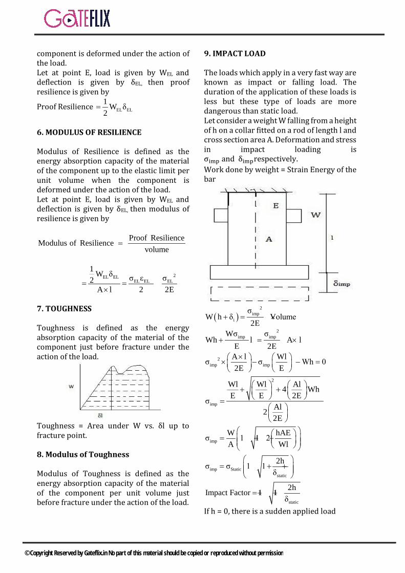
9. IMPACT LOAD The loads which apply in a very fast way are known as impact or falling load. The duration of the application of these loads is less but these type of loads are more dangerous than static load. Let consider a weight W falling from a height of h on a collar fitted on a rod of length l and cross section area A. Deformation and stress in impact loading is σimp and δimprespectively. Work done by weight = Strain Energy of the bar
( )2
impi
σW h δ Volume
2E+ = ×
2imp impWσ σ
Wh l A lE 2E
+ = × ×
2imp imp
A l Wlσ σ Wh 02E E× × − − =
2
imp
Wl Wl Al4 Wh E E 2Eσ
Al22E
+ + =
impW hAEσ 1 1 2A Wl = + +
imp Staticstatic
2hσ σ 1 1δ
= + +
static
2hImpact Factor 1 1δ
= + +
If h = 0, there is a sudden applied load
© Copyright Reserved by Gateflix.in No part of this material should be copied or reproduced without permission

Impact factor for sudden applied load = 2 So, Impact factor 2≥
imp Staticσ 2σ≥
© Copyright Reserved by Gateflix.in No part of this material should be copied or reproduced without permission
Q.1 A uniform, slender cylindrical rod is made of a homogeneous and isotropic material. The rod rests on a frictionless surface. The rod is heated uniformly. If the radial and longitudinal thermal stresses are represented by σr and σz , respectively, then a) σr = 0, σz = 0 b) σr ≠ 0, σz =0 c) σr = 0, σz ≠ 0 d) σr ≠ 0, σz ≠0
[GATE-2005]
Q.2 A steel rod of length L and diameter D , fixed at both ends, is uniformly heated to a temperature rise of ∆T . The Young's modulus is E and the co-efficient of linear expansion is α. The thermal stress in the rod is a) 0 b) α∆Tc) E α∆T d) E α∆TL
[GATE-2007]
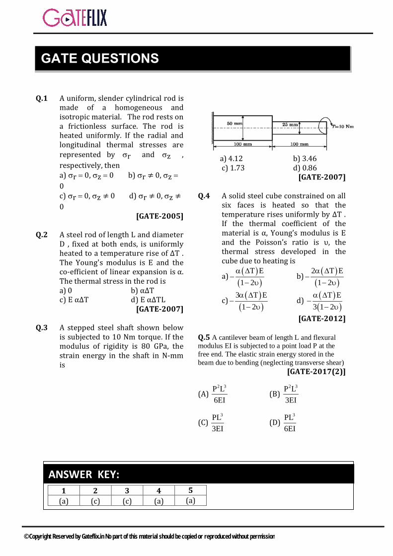
Q.3 A stepped steel shaft shown below is subjected to 10 Nm torque. If the modulus of rigidity is 80 GPa, the strain energy in the shaft in N-mm is
a) 4.12 b) 3.46c) 1.73 d) 0.86
[GATE-2007]
Q.4 A solid steel cube constrained on all six faces is heated so that the temperature rises uniformly by ΔT . If the thermal coefficient of the material is α, Young’s modulus is E and the Poisson’s ratio is υ, the thermal stress developed in the cube due to heating is
a) ( )( )
T E1 2
α ∆−
− υ b) ( )
( )2 T E
1 2α ∆
−− υ
c) ( )( )
3 T E1 2
α ∆−
− υ d) ( )
( )T E
3 1 2α ∆
−− υ
[GATE-2012]
Q.5 A cantilever beam of length L and flexural modulus EI is subjected to a point load P at the free end. The elastic strain energy stored in the beam due to bending (neglecting transverse shear)
[GATE-2017(2)]
(A) 2 3P L
6EI(B)
2 3P L3EI
(C) 3PL
3EI(D)
3PL6EI
1 2 3 4 5 (a) (c) (c) (a) (a)
ANSWER KEY:
GATE QUESTIONS
© Copyright Reserved by Gateflix.in No part of this material should be copied or reproduced without permission

Q.1 (a) We know that due to temperature changes, dimensions of the material change. If these changes in the dimensions are prevented partially or fully, stresses are generated in the material and if the changes in the dimensions are not prevented, there will be no stress set up. (Zero stresses). So, σρ = 0 ανδ σζ = 0
Q.2 (c)
Q.3 (c) Given : T = 10 N m = 104 N mm G = 80 GPa = 80 ×103 N/mm2 L1 = L2 = 100 mm, d1 = 50 mm, d2 = 25 mm We know that for a shaft of length l and polar moment of inertia J, subjected to a torque T with an angle of twist θ. The expression of strain energy,
U 1 T θ2
= × × and TLGJ
θ = .
So total strain energy 2
1 2
T L 1 1U2G J J
= +
Where ( )4πJ d32
=
Substituting the values, we get U = 1.73 N-mm
Q.4 (a) Let the side of cube be ’a’
Now since the cube is uniformly constrained to expand, the stress produced in all the three directions will be same ∴ Strain in x direction
( ) yx xυσσ υσα TE E E
− ∆ = − −
x y zσ σ σ σ= = =
( )α T Eσ
(1 2υ)=∴
∆−
−
Q.5 (a) There can be more than one Possibility. So identities P,Q cannot be determined.
EXPLANATIONS
© Copyright Reserved by Gateflix.in No part of this material should be copied or reproduced without permission
3.1 SHEAR FORCE & BENDING MOMENT
1. SHEAR FORCE
Shear force is defined at the vertical force at the section of a beam. The Shear force is given by summation of all vertical forces acting at the section of the beam either left or right of the section.
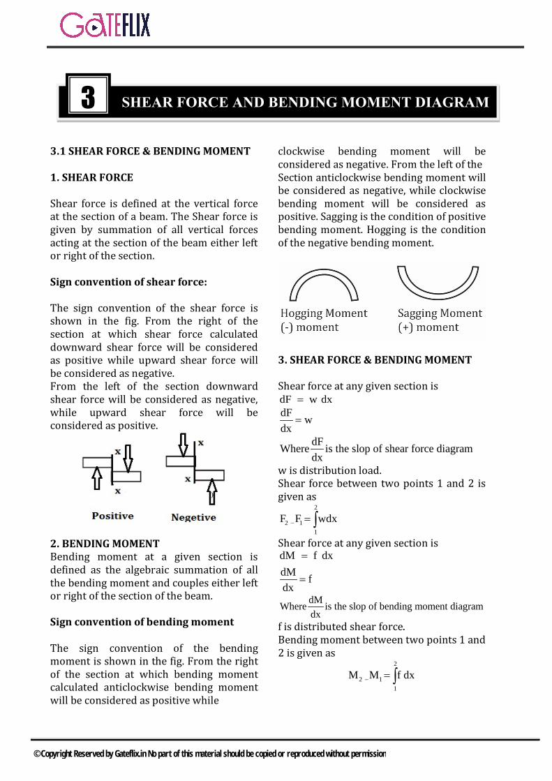
Sign convention of shear force:
The sign convention of the shear force is shown in the fig. From the right of the section at which shear force calculated downward shear force will be considered as positive while upward shear force will be considered as negative. From the left of the section downward shear force will be considered as negative, while upward shear force will be considered as positive.
2. BENDING MOMENTBending moment at a given section is defined as the algebraic summation of all the bending moment and couples either left or right of the section of the beam.
Sign convention of bending moment
The sign convention of the bending moment is shown in the fig. From the right of the section at which bending moment calculated anticlockwise bending moment will be considered as positive while
clockwise bending moment will be considered as negative. From the left of the Section anticlockwise bending moment will be considered as negative, while clockwise bending moment will be considered as positive. Sagging is the condition of positive bending moment. Hogging is the condition of the negative bending moment.
3. SHEAR FORCE & BENDING MOMENT
Shear force at any given section is dF w dx = dF wdx
=
dFWhere is the slop of shear force diagramdx
w is distribution load. Shear force between two points 1 and 2 is given as
2
2 11
F F wdx− = ∫Shear force at any given section is dM f dxdM fdx
=
=
dMWhere is the slop of bending moment diagramdx
f is distributed shear force. Bending moment between two points 1 and 2 is given as
2
2 11
M M f dx− = ∫
3 SHEAR FORCE AND BENDING MOMENT DIAGRAM
© Copyright Reserved by Gateflix.in No part of this material should be copied or reproduced without permission

Note: Variation of shear force and bending moment diagram
S. No. Load SFD BMD 1 Point Load Horizontal Line Inclined Line 2 UDL Inclined Line Parabolic Curve 3 IVL Parabolic Curve Cubic Parabolic Curve 4 Pure Bending Zero Value Horizontal Line
3.2 BEAMS 1. BEAM Beam is defined as any structural member which is subjected under transverse loads. Due to the transverse loading, there is a variation of shear force and bending moment over the entire span of the beam. So it is better to draw SFD and BMD to check the maximum value of shear force and bending moment. 2. SUPPORTS: (i) ROLLER SUPPORTS: Roller supports are free to rotate and translate along the surface upon which the roller rests. The surface can be horizontal, vertical, or sloped at any angle. The resulting reaction force is always a single force that is perpendicular to, and away from, the surface. Roller supports are commonly located at one end of long bridges. This allows the bridge structure to expand and contract with temperature changes. The expansion forces could fracture the supports at the banks if the bridge structure was "locked" in place. Roller supports can also take the form of rubber bearings, rockers, or a set of gears which are designed to allow a limited amount of lateral movement. A roller support cannot provide resistance to lateral forces. Imagine a structure (perhaps a person) on roller skates. It would remain in place as long as the structure must only support itself and perhaps a perfectly vertical load. As soon as a lateral load of any kind pushes on the structure it will roll away in response to
the force. The lateral load could be a shove, a gust of wind or an earthquake. Since most structures are subjected to lateral loads it follows that a building must have other types of support in addition to roller supports. (ii) PINNED SUPPORTS A pinned support can resist both vertical and horizontal forces but not a moment. They will allow the structural member to rotate, but not to translate in any direction. Many connections are assumed to be pinned connections even though they might resist a small amount of moment in reality. It is also true that a pinned connection could allow rotation in only one direction; providing resistance to rotation in any other direction. The knee can be idealized as a connection which allows rotation in only one direction and provides resistance to lateral movement. The design of a pinned connection is a good example of the idealization of the reality. A single pinned connection is usually not sufficient to make a structure stable. Another support must be provided at some point to prevent rotation of the structure. The representation of a pinned support includes both horizontal and vertical forces. (iii) FIXED SUPPORTS Fixed supports can resist vertical and horizontal forces as well as a moment. Since they restrain both rotation and translation, they are also known as rigid supports. This means that a structure only needs one fixed support in order to be stable. All three equations of equilibrium can be satisfied. A flagpole set into a concrete base is a good example of this kind of support. The representation of fixed supports always includes two forces (horizontal and vertical) and a moment. (iv) SIMPLE SUPPORTS
© Copyright Reserved by Gateflix.in No part of this material should be copied or reproduced without permission
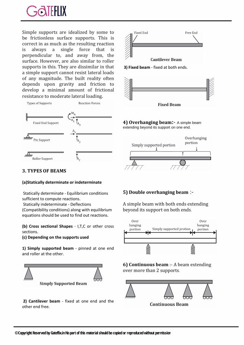
Simple supports are idealized by some to be frictionless surface supports. This is correct in as much as the resulting reaction is always a single force that is perpendicular to, and away from, the surface. However, are also similar to roller supports in this. They are dissimilar in that a simple support cannot resist lateral loads of any magnitude. The built reality often depends upon gravity and friction to develop a minimal amount of frictional resistance to moderate lateral loading.
3. TYPES OF BEAMS (a)Statically determinate or indeterminate
Statically determinate - Equilibrium conditions sufficient to compute reactions. Statically indeterminate - Deflections (Compatibility conditions) along with equilibrium equations should be used to find out reactions. (b) Cross sectional Shapes - I,T,C or other cross sections. (c) Depending on the supports used 1) Simply supported beam - pinned at one end and roller at the other.
2) Cantilever beam - fixed at one end and the other end free.
3) Fixed beam - fixed at both ends.
4) Overhanging beam:- A simple beam extending beyond its support on one end.
5) Double overhanging beam :-
A simple beam with both ends extending beyond its support on both ends.
6) Continuous beam :- A beam extending over more than 2 supports.
© Copyright Reserved by Gateflix.in No part of this material should be copied or reproduced without permission

3.3 Free-Body Diagrams
Before calculating for the support reactions on a body, a free-body diagram should be drawn. A free-body diagram is a representation of a body that is free from any support or external object; however, the forces and moments from the supports attached to the body are to be considered when drawing a free-body diagram, along with any other external forces or moments. If there is a force that acts in both the x and y direction (i.e. the force is on an angle), it must be broken up into its respective x and y components. Once all the known and unknown forces are drawn, the free-body diagram is complete. From here, all the forces that need to be solved can be clearly seen, and their respective directions clearly labeled, therefore all forces and moments are able to be separated into their respective equations of equilibrium. All forces in the x-direction are to be placed into the x-direction equation of equilibrium; the same procedure is used for the y-direction as well as all the moments that act on the body.
3.4 Method of Analysis.
1. Draw the Free-Body Diagram including all applied forces and support reactions. 2. Using the Equations of Equilibrium, solve reactions if possible.
3. For more complicated structures, it may be cut into sections. Sections should be cut between every time the loading condition changes. It is also useful to cut at hinges where no moments occur.
4. Continue using the Equilibrium equations to solve the structure. 5. Redraw the Free-Body Diagram with forces and reactions in the correct directions. A negative answer shows that the direction drawn on the initial Free-Body Diagram was assumed incorrectly.
3.5 Equations of Equilibrium
The equations of equilibrium are as follows: 1. Fx 0 ∑ = , Equation 1 represents the sum of all the forces acting on a body in the x direction, and states that this sum must be equal to zero. 2. Fy 0 ∑ = , Equation 2 represents the sum of all the forces acting on a body in the y direction, and states that this sum must be equal to zero. 3. Mo 0 ∑ = , Equation 3 represents the sum of all the couple moments and the moments caused by all force components acting on the member around the z axis, which is perpendicular to both the x and y axis and passes through an arbitrary point o.
3.6 EXAMPLE PROBLEMS
Problem 1
Solve the following support reactions.
© Copyright Reserved by Gateflix.in No part of this material should be copied or reproduced without permission
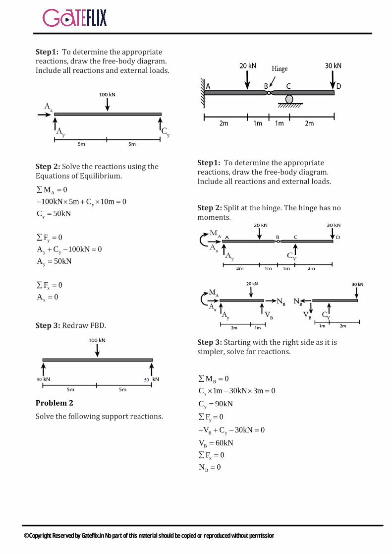
Step1: To determine the appropriate reactions, draw the free-body diagram. Include all reactions and external loads.
Step 2: Solve the reactions using the Equations of Equilibrium.
A
y
y
y
y y
y
x
x
M 0100kN 5m C 10m 0
C 50kN
F 0A C 100kN 0A 50kN
F 0A 0
∑ =− × + × =
=
∑ =+ − ==
∑ ==
Step 3: Redraw FBD.
Problem 2
Solve the following support reactions.
Step1: To determine the appropriate reactions, draw the free-body diagram. Include all reactions and external loads.
Step 2: Split at the hinge. The hinge has no moments.
Step 3: Starting with the right side as it is simpler, solve for reactions.
B
y
y
y
B y
B
x
B
M 0C 1m 30kN 3m 0C 90kN
F 0V C 30kN 0
V 60kN F 0
N 0
∑ =× − × =
=
∑ =
− + − =
=∑ =
=
© Copyright Reserved by Gateflix.in No part of this material should be copied or reproduced without permission

Step 4: Transfer the internal reactions to the other side of the hinge. Solve for remaining unknowns.
A
A
A
y
y B
y
x
x
M 0M 20kN 2m 60kN 3m 0
M 140kNmF 0
A V 20kN 0A 40kN
F 0A 0
∑ =− − × + × =
=∑ =
+ − =
= −
∑ ==
Step 5: Redraw FBD.
Step 6: Check the answers by checking the equilibrium of the entire system.
A
y
x
M 0140kNm 20kN 2m 90kN 4m 30kN 6m 0
0 0F 0
40kN 20kN 90kN 30kN 00 0
F 00 0
∑ =− − × + × − × ==
∑ =
− − + − ==
∑ ==
3.7 SPECIAL CASE OF SHEAR FORCE DIAGRAM AND BENDING MOMENT DIAGRAM Case (A) Cantilevers Beam
i) Cantilever of length l carrying a concentrated load W at the free end
Sx = - w Mx = - W.x Mmax = - Wl
ii) Cantilever of length l carrying a
uniformly distributed load of w per unit run over the whole length Sx = - wx
2
xwxM
2= −
2
maxwlM2
= −
maxS wl= −
© Copyright Reserved by Gateflix.in No part of this material should be copied or reproduced without permission
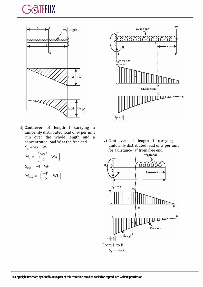
iii) Cantilever of length l carrying a uniformly distributed load of w per unit run over the whole length and a concentrated load W at the free end.
xS wx W= + 2
xwxM Wx
2
= − +
maxS wl W= + 2
maxwlM WI2
= − +
iv) Cantilever of length l carrying a uniformly distributed load of w per unit for a distance “a” from free end.
From D to B
xS wx= +
© Copyright Reserved by Gateflix.in No part of this material should be copied or reproduced without permission
2
xwxM
2= −
from D to A
xS wa= +
xaM wa x2
= − −
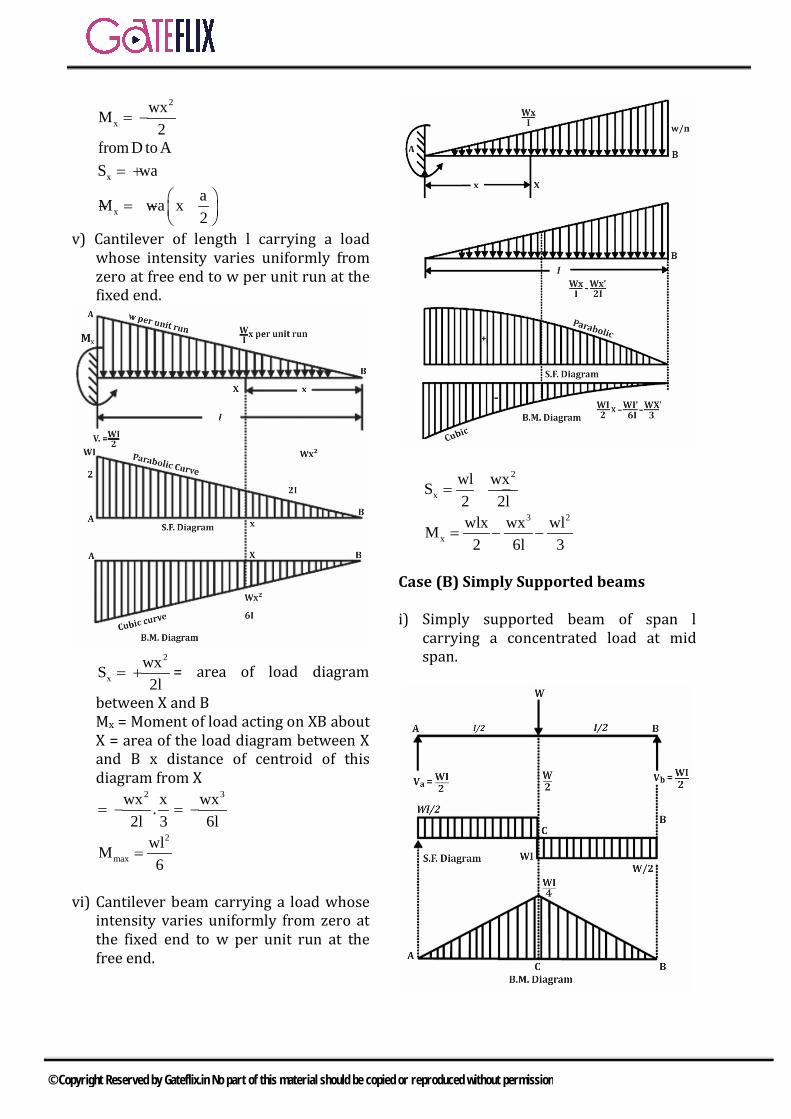
v) Cantilever of length l carrying a load whose intensity varies uniformly from zero at free end to w per unit run at the fixed end.
2
xwxS2l
= + = area of load diagram
between X and B Mx = Moment of load acting on XB about X = area of the load diagram between X and B x distance of centroid of this diagram from X
2wx x.2l 3
= −3wx
6l= −
2
maxwlM6
=
vi) Cantilever beam carrying a load whose
intensity varies uniformly from zero at the fixed end to w per unit run at the free end.
2
xwl wxS2 2l
= −
3 2
xwlx wx wlM
2 6l 3= − −
Case (B) Simply Supported beams i) Simply supported beam of span l
carrying a concentrated load at mid span.
© Copyright Reserved by Gateflix.in No part of this material should be copied or reproduced without permission

xWS (betweenAC)2
= +
W (between CB)2
= −
xWM x (from A to C) (at a dis tan ce x`from A)2
= +
max CWlM M4
= =
ii) Simply supported beam carrying a concentrated load eccentrically the span. The load W is subjected at the length ‘a’ from one end and at ‘b’ from the other end. Shear stress between A and D can be given as
xWbS (from A to D)
l= +
Wa (from D to B)l
= −
at a dis tan ce x`from A
max DWabM M
l= =
Note: Maximum B.M. occurs where S.F. changes its sign.
iii) Simply supported beam carrying a
uniformly distributed load of w per unit run over the whole span
xwlS wx2
= −
2
xwl wxM .x2 2
= −
2
max CwlM M8
= =
iv) Simply supported beam carrying a load whose intensity varies uniformly from zero at each end to w per unit run at the mid span.
© Copyright Reserved by Gateflix.in No part of this material should be copied or reproduced without permission
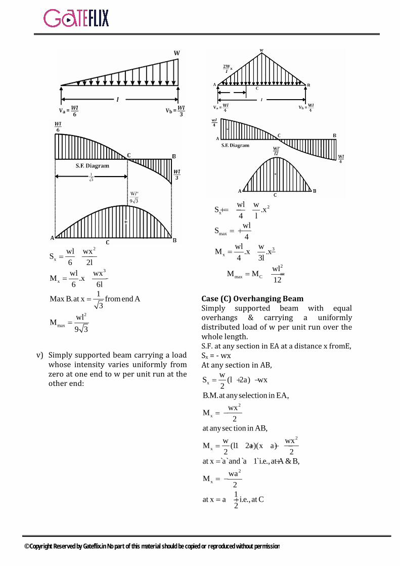
2
xwl wxS6 2l
= −
3
xwl wxM .x6 6l
= −
1Max B.at x from end A3
=
2
maxwlM9 3
=
v) Simply supported beam carrying a load whose intensity varies uniformly from zero at one end to w per unit run at the other end:
2
xwl wS .x4 l
= + −
maxwlS4
= +
3x
wl wM .x .x4 3l
= −
2
max CwlM M12
= =
Case (C) Overhanging Beam Simply supported beam with equal overhangs & carrying a uniformly distributed load of w per unit run over the whole length. S.F. at any section in EA at a distance x fromE, Sx = - wx At any section in AB,
xwS (l 2a) wx2
= + −
B.M.at anyselection in EA, 2
xwxM
2= −
at anysec tion in AB, 2
xw wxM (l1 2a)(x a)2 2
= + − −
at x a`and a 1 i.e., at A & B,= + 2
xwaM
2= −
1at x a i.e., at C2
= +
© Copyright Reserved by Gateflix.in No part of this material should be copied or reproduced without permission
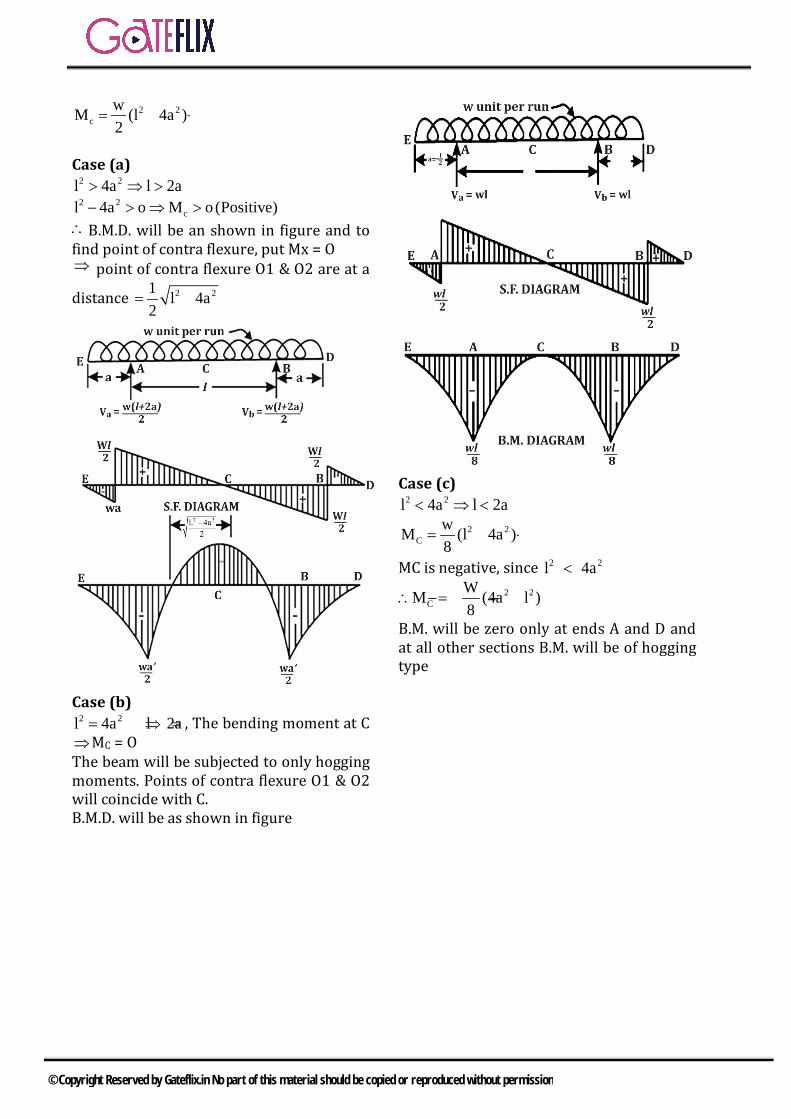
2 2c
wM (l 4a )2
= −
Case (a)
2 2l 4a l 2a> ⇒ > 2 2
cl 4a o M o(Positive)− > ⇒ > ∴B.M.D. will be an shown in figure and to find point of contra flexure, put Mx = O ⇒ point of contra flexure O1 & O2 are at a
distance 2 21 l 4a2
= −
Case (b)
2 2l 4a l 2a= ⇒ = , The bending moment at C ⇒MC = O
The beam will be subjected to only hogging moments. Points of contra flexure O1 & O2 will coincide with C.
B.M.D. will be as shown in figure
Case (c)
2 2l 4a l 2a< ⇒ <
2 2C
wM (l 4a )8
= −
MC is negative, since 2 2l 4a<
2 2C
WM (4a l )8
∴ = − −
B.M. will be zero only at ends A and D and at all other sections B.M. will be of hogging type
© Copyright Reserved by Gateflix.in No part of this material should be copied or reproduced without permission
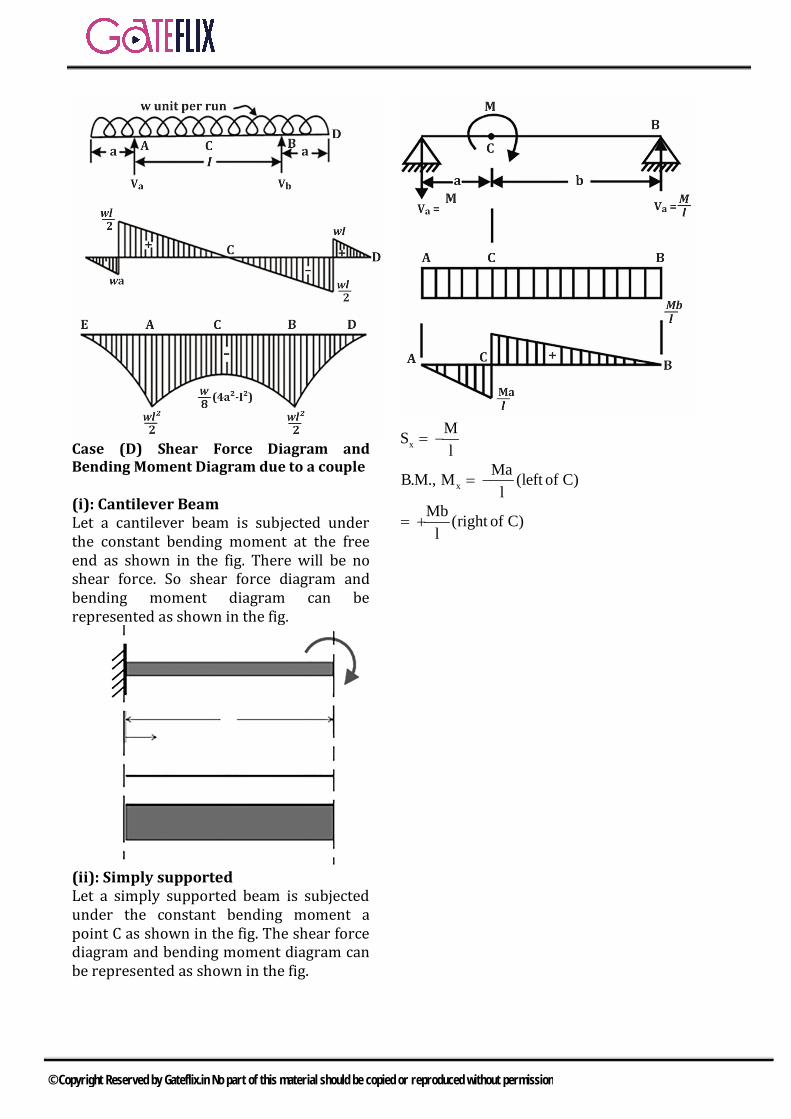
Case (D) Shear Force Diagram and Bending Moment Diagram due to a couple (i): Cantilever Beam Let a cantilever beam is subjected under the constant bending moment at the free end as shown in the fig. There will be no shear force. So shear force diagram and bending moment diagram can be represented as shown in the fig.
(ii): Simply supported Let a simply supported beam is subjected under the constant bending moment a point C as shown in the fig. The shear force diagram and bending moment diagram can be represented as shown in the fig.
xMSl
= −
B.M., xMaM (left of C)
l= −
Mb (right of C)l
= +
© Copyright Reserved by Gateflix.in No part of this material should be copied or reproduced without permission

Q.1 A cantilever beam carries the anti-symmetric load shown, where w0 is the peak intensity of the distributed load. Qualitatively, the correct bending moment diagram for this beam is
a) b)
c) d)
[GATE-2005]
Q.2 A cantilever beam has the square cross section of 10 mm × 10 mm. It carries a transverse load of 10 N. Consider only the bottom fibers of the beam, the correct representation of the longitudinal variation of the bending stress is a) b)
c) d)
[GATE-2005]
Q.3 A simply supported beam of length L is subjected to a varying
distributed load 3πxsin( )L
Nm−1
where the distance x is measured from the left support. The
magnitude of the vertical reaction force in N at the left support is
a) Zero b) L3π
c) Lπ
d) 2Lπ
[GATE-2013]
Q.4 A cantilever beam OP is connected to another beam PQ with a pin joint as shown in the figure. A load of 10 kN is applied at midpoint of PQ. The magnitude of bending moment (in kN-m) at fixed end O is______.
a) 2.5 b) 5c) 10 d) 25
[GATE-2015(2)]
Q.5 For the overhanging beam shown in figure, the magnitude of maximum bending moment (in kN-m) is _____
[GATE-2015(3)]
GATE QUESTIONS
© Copyright Reserved by Gateflix.in No part of this material should be copied or reproduced without permission
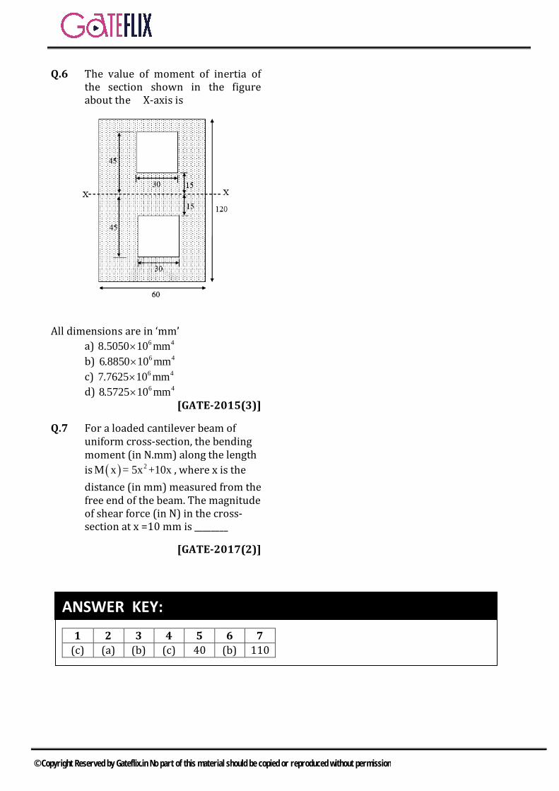
Q.6 The value of moment of inertia of the section shown in the figure about the X-axis is
All dimensions are in ‘mm’
a) 6 48.5050 10 mm× b) 6 46 18850 0. mm× c) 6 47 17625 0. mm× d) 6 48 15725 0. mm×
[GATE-2015(3)]
Q.7 For a loaded cantilever beam of uniform cross-section, the bending moment (in N.mm) along the length is ( ) 2M x = 5x +10x , where x is the distance (in mm) measured from the free end of the beam. The magnitude of shear force (in N) in the cross- section at x =10 mm is ________
[GATE-2017(2)]
1 2 3 4 5 6 7 (c) (a) (b) (c) 40 (b) 110
ANSWER KEY:
© Copyright Reserved by Gateflix.in No part of this material should be copied or reproduced without permission
Q.1 (c)
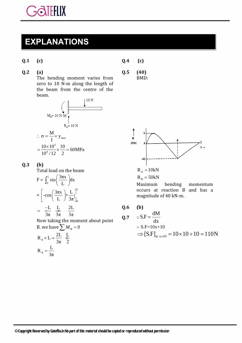
Q.2 (a) The bending moment varies from zero to 10 N-m along the length of the beam from the centre of the beam.
maxM yI×∴σ =
3
4
10 10 10 60MPa10 /12 2
× ==×
Q.3 (b) Total load on the beam
F = L
0
3πxsin dxL
∫
= L
0
3πx L-cos ×L 3π
L L 2L3π 3π 3π−
= − − =
Now taking the moment about point B. we have 0=∑ BM
A2L LR L3π 2
× = ×
ALR3π
=
Q.4 (c)
Q.5 (40) BMD:
AR 10kN=
BR 50kN=Maximum bending momentum occurs at reaction B and has a magnitude of 40 kN-m.
Q.6 (b)
Q.7 ∵dMS.Fdx
=
∴ S.F=10x+10
at x 10[S.F] 10 10 10 110N=⇒ = × + =
EXPLANATIONS
© Copyright Reserved by Gateflix.in No part of this material should be copied or reproduced without permission

4.1 PURE BENDING MOMENT
A member is said to be under pure bending moment when it subjected to two equal and opposite couple in the plane passing through the axis of the beam.
Fig. Pure bending
1. EULER BERNOULLI’S EQUATION OR(BENDING STRESS FORMULA) OR BENDING EQUATION
M σ E I y R= =
( )
Where Bending Stress M Bending Moment I Moment of Inertia E Modulus of elasticity R Radius of curvature y Distance of the fibre from NA Neutral axis
σ ==
====
2. Assumptions in Simple BendingTheory All of the foregoing theory has been developed for the case of pure bending i.e. constant B.M along the length of the beam. In such case:
• The shear force at each c/s is zero.• Normal stress due to bending is only
produced.• Beams are initially straight• •
• The material is homogenous andisotropic i.e. it has a uniformcomposition and its mechanical
• properties are the same in alldirections
• The stress-strain relationship islinear and elastic
• Young’s Modulus is the same intension as in compression
• Sections are symmetrical about theplane of bending
• Sections which are plane beforebending remain plane after bending
3. BENDING STRESS DISTRIBUTION
As per bending stress equation, bending stress is directly proportional to y, extreme fiber of the component from the neutral axis is under the maximum bending stress. For the symmetrical cross section, extreme fiber will be under same amount of stress but for unsymmetrical cross section extreme fiber will not be under same amount of bending stress.
Fig. Bending stress distribution So the bending strain can be given as
yyεR
= ±
It means if at the top side from neutralaxis is tensile bending stress thenbottom side from neutral axis will havecompressive bending stressAs per Hook’s law, up to elastic limit
by yσ ε y∝ ∝
4 BENDING STRESS AND SHEAR STRESS
© Copyright Reserved by Gateflix.in No part of this material should be copied or reproduced without permission

by yyσ Eε ER
= = ±
byσ Ey R
=
So the ratio of bending stress and strain at the top of the fiber and bottom of the fiber is given as
ytop top
ybottom bottom
ε yε y
=
bytop ytop top
bybottom ybottom bottom
σ ε yσ ε y
= =
4. Section Modulus(Z) Iy
Z =
• Z is a function of beam cross section only • It is also called the strength of the beam • Section modulus is the first moment of area about the axis of bending for a beam cross-section • The strength of the beam sections depends mainly on the section modulus
The flexural formula may be written as.
The flexural formula may be written as. MZ
=
Rectangular cross section of width is ‘‘b’’ &
depth ‘’h’’ with sides horizontal:2
6bhZ =
Square beam with sides horizontal:3
6aZ =
Square cross section with diagonal horizontal :
3
6 2aZ =
Circular cross section of diameter ‘‘d’’ 3
32dZ π
=
5. Flexural Rigidity (EI) Reflects both
• Stiffness of the material (measured by E)
• Proportions of the cross section area(measured by I )
4.2 BEAM UNDER UNIFORM STRENGTH A beam is said to be under uniform bending strength if the bending stress developed is same on every cross section along the length of the beam.
b 2 2xx
2
M 6M 6PxσZ bd bd
For uniform strength M bd
= = =
∝
So uniform bending strength can be achieved by varying width of the cross section or depth of the cross section. There are following methods: a) By changing the width and keeping depth as constant Let d and b are depth and width of the cross section at the fixed end as shown in the fig. The length of the beam is l, then for uniform strength
b2 2 b3 3σ σ− −=
2 2x
6Px 6Plb d bd
=
© Copyright Reserved by Gateflix.in No part of this material should be copied or reproduced without permission
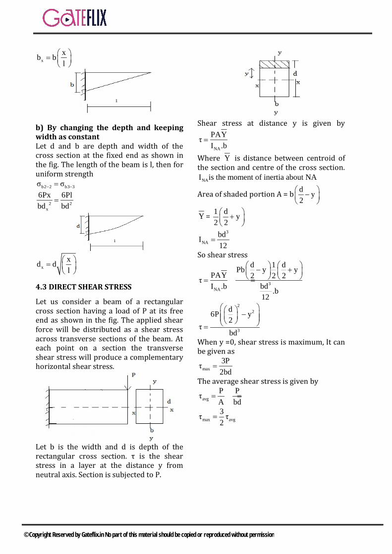
xxb bl
=
b) By changing the depth and keeping width as constant Let d and b are depth and width of the cross section at the fixed end as shown in the fig. The length of the beam is l, then for uniform strength
b2 2 b3 3σ σ− −=
2 2x
6Px 6Plbd bd
=
xxd dl
=
4.3 DIRECT SHEAR STRESS
Let us consider a beam of a rectangular cross section having a load of P at its free end as shown in the fig. The applied shear force will be distributed as a shear stress across transverse sections of the beam. At each point on a section the transverse shear stress will produce a complementary horizontal shear stress.
Let b is the width and d is depth of the rectangular cross section. τ is the shear stress in a layer at the distance y from neutral axis. Section is subjected to P.
Shear stress at distance y is given by
NA
PAYτI .b
=
Where Y is distance between centroid of the section and centre of the cross section.
NAI is the moment of inertia about NA
Area of shaded portion A = b d y2
−
Y = 1 d y2 2 +
3
NAbdI12
=
So shear stress
3NA
d 1 dPb y yPAY 2 2 2τ
bdI .b .b12
− + = =
22
3
d6P y2
τbd
− =
When y =0, shear stress is maximum, It can be given as
max3Pτ2bd
=
The average shear stress is given by
avgP PτA bd
= =
max avg3τ τ2
=
© Copyright Reserved by Gateflix.in No part of this material should be copied or reproduced without permission

1 .SHEAR STRESS DISTRIBUTION Shear stress is a parabolic function of y for the rectangular cross section. So the shear stress distribution can be given by
Shear stress distribution for I section is given by
Shear stress distribution for T section is given as
Shear stress distribution for L section is given as
Shear stress distribution for Hollow circular section is given as
Shear stress distribution for Cross section is given as
2. SHEAR CENTRE
Shear centre of a section can be defined as a point about which the applied force is
© Copyright Reserved by Gateflix.in No part of this material should be copied or reproduced without permission
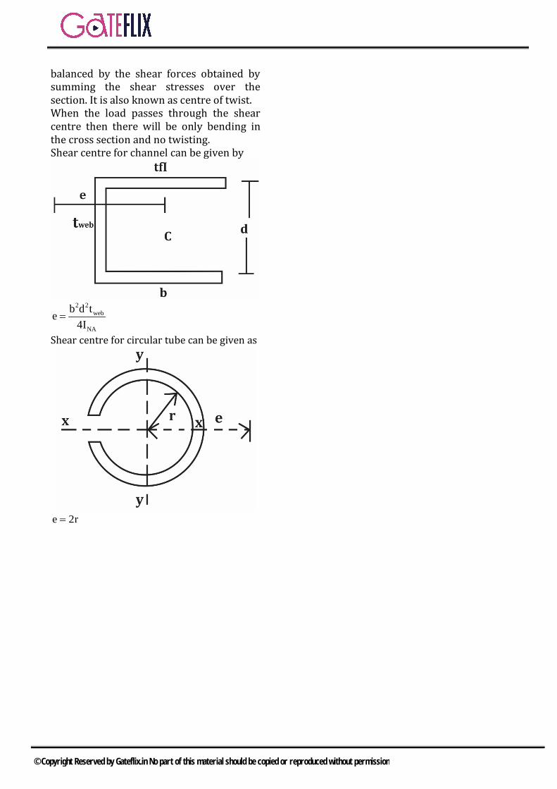
balanced by the shear forces obtained by summing the shear stresses over the section. It is also known as centre of twist. When the load passes through the shear centre then there will be only bending in the cross section and no twisting. Shear centre for channel can be given by
2 2
web
NA
b d te4I
=
Shear centre for circular tube can be given as
e 2r=
© Copyright Reserved by Gateflix.in No part of this material should be copied or reproduced without permission

Q.1 The second moment of a circular area about the diameter is given by (D is the diameter). a) 4πd / 4 b) 4πd /16c) 4πd / 32 d) 4πd / 64
[GATE-2003]
Q.2 A concentrated load of P acts on a simply supported beam of span L at a distance L/3 from the left support. The bending moment at the point of application of the load is given by a) PL/3 b) 2PL/3c) PL/9 d) 2PL/9
[GATE-2003]
Q.3 The beams, one having square cross section and another circular cross-section, are subjected to the same amount of bending moment. If the cross sectional area as well as the material of both the beams are same then a) maximum bending stress
developed in both the beams is same
b) the circular beam experiencemore bending stress than the square one
c) the square beam experiencemore bending stress than the circular one
d) as the material is same, both thebeams will experience same deformation.
[GATE-2003]
Q.4 A simply supported laterally loaded beam was found to deflect more than a specified value. Which of the following measures will reduce the deflection? a) Increase the area moment of
inertia
b) Increase the span of the beamc) Select a different material
having lesser modulus ofelasticity
d) Magnitude of the load to beincreased
[GATE-2003]
Common Data For Q.5 and 6 are given below. A steel beam of breadth 120 mm and height 750 mm is loaded as shown in the figure. Assume Esteel = 200 GPa.
Q.5 The beam is subjected to a maximum bending moment of a) 3375 kN-m b) 4750 kN-mc) 6750 kN-m d) 8750 kN-m
[GATE-2004]
Q.6 The value of maximum deflection of the beam is a) 93.75 mm b) 83.75 mmc) 73.75 mm d) 63.75 mm
[GATE-2004]
Q.7 Two identical cantilever beams are supported as shown, with their free ends in contact through a rigid roller. After the load P is applied, the free ends will have
GATE QUESTIONS
© Copyright Reserved by Gateflix.in No part of this material should be copied or reproduced without permission
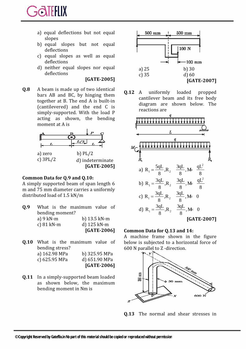
a) equal deflections but not equal slopes
b) equal slopes but not equal deflections
c) equal slopes as well as equal deflections
d) neither equal slopes nor equal deflections
[GATE-2005]
Q.8 A beam is made up of two identical bars AB and BC, by hinging them together at B. The end A is built-in (cantilevered) and the end C is simply-supported. With the load P acting as shown, the bending moment at A is
a) zero b) PL/2
c) 3PL/2 d) indeterminate [GATE-2005]
Common Data for Q.9 and Q.10: A simply supported beam of span length 6 m and 75 mm diameter carries a uniformly distributed load of 1.5 kN/m Q.9 What is the maximum value of
bending moment? a) 9 kN-m b) 13.5 kN-m
c) 81 kN-m d) 125 kN-m [GATE-2006]
Q.10 What is the maximum value of
bending stress? a) 162.98 MPa b) 325.95 MPa c) 625.95 MPa d) 651.90 MPa
[GATE-2006] Q.11 In a simply-supported beam loaded
as shown below, the maximum bending moment in Nm is
a) 25 b) 30 c) 35 d) 60
[GATE-2007] Q.12 A uniformly loaded propped
cantilever beam and its free body diagram are shown below. The reactions are
a) 2
1 25qL 3qL qLR ,R ,M
8 8 8= = =
b) 2
1 23qL 3qL qLR ,R ,M
8 8 8= = =
c) 1 23qL 3qLR ,R ,M 0
8 8= = =
d) 1 23qL 3qLR ,R ,M 0
8 8= = =
[GATE-2007] Common Data for Q.13 and 14: A machine frame shown in the figure below is subjected to a horizontal force of 600 N parallel to Z -direction.
Q.13 The normal and shear stresses in
© Copyright Reserved by Gateflix.in No part of this material should be copied or reproduced without permission
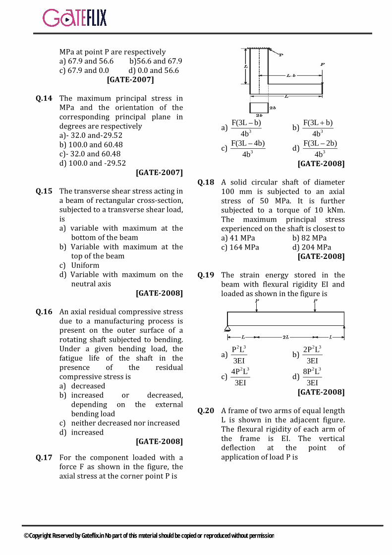
MPa at point P are respectively a) 67.9 and 56.6 b)56.6 and 67.9
c) 67.9 and 0.0 d) 0.0 and 56.6 [GATE-2007] Q.14 The maximum principal stress in
MPa and the orientation of the corresponding principal plane in degrees are respectively
a)- 32.0 and-29.52 b) 100.0 and 60.48 c)- 32.0 and 60.48
d) 100.0 and -29.52 [GATE-2007]
Q.15 The transverse shear stress acting in
a beam of rectangular cross-section, subjected to a transverse shear load, is a) variable with maximum at the
bottom of the beam b) Variable with maximum at the
top of the beam c) Uniform d) Variable with maximum on the
neutral axis [GATE-2008]
Q.16 An axial residual compressive stress
due to a manufacturing process is present on the outer surface of a rotating shaft subjected to bending. Under a given bending load, the fatigue life of the shaft in the presence of the residual compressive stress is a) decreased b) increased or decreased,
depending on the external bending load
c) neither decreased nor increased d) increased
[GATE-2008]
Q.17 For the component loaded with a force F as shown in the figure, the axial stress at the corner point P is
a) 3
F(3L – b)4b
b) 3F(3L b)
4b+
c) 3F(3L – 4b)
4b d) 3
F(3L – 2b)4b
[GATE-2008]
Q.18 A solid circular shaft of diameter 100 mm is subjected to an axial stress of 50 MPa. It is further subjected to a torque of 10 kNm. The maximum principal stress experienced on the shaft is closest to a) 41 MPa b) 82 MPa c) 164 MPa d) 204 MPa
[GATE-2008] Q.19 The strain energy stored in the
beam with flexural rigidity EI and loaded as shown in the figure is
a) 2 3P L
3EI b)
2 32P L3EI
c) 2 34P L
3EI d)
2 38P L3EI
[GATE-2008] Q.20 A frame of two arms of equal length
L is shown in the adjacent figure. The flexural rigidity of each arm of the frame is EI. The vertical deflection at the point of application of load P is
© Copyright Reserved by Gateflix.in No part of this material should be copied or reproduced without permission
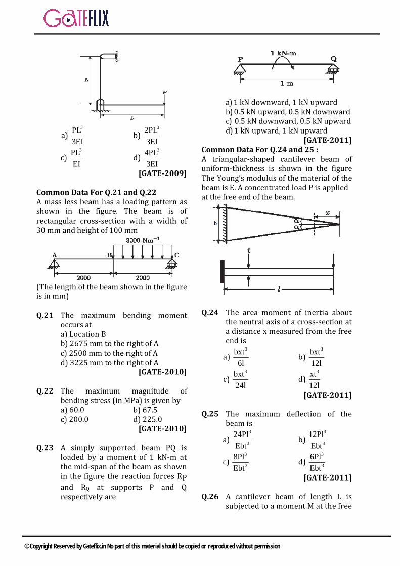
a) 3PL
3EI b)
32PL3EI
c) 3PL
EI d)
34PL3EI
[GATE-2009] Common Data For Q.21 and Q.22 A mass less beam has a loading pattern as shown in the figure. The beam is of rectangular cross-section with a width of 30 mm and height of 100 mm
(The length of the beam shown in the figure is in mm) Q.21 The maximum bending moment
occurs at a) Location B
b) 2675 mm to the right of A c) 2500 mm to the right of A
d) 3225 mm to the right of A [GATE-2010]
Q.22 The maximum magnitude of
bending stress (in MPa) is given by a) 60.0 b) 67.5 c) 200.0 d) 225.0
[GATE-2010] Q.23 A simply supported beam PQ is
loaded by a moment of 1 kN-m at the mid-span of the beam as shown in the figure the reaction forces RP and RQ at supports P and Q respectively are
a) 1 kN downward, 1 kN upward b) 0.5 kN upward, 0.5 kN downward
c) 0.5 kN downward, 0.5 kN upward d) 1 kN upward, 1 kN upward
[GATE-2011] Common Data For Q.24 and 25 : A triangular-shaped cantilever beam of uniform-thickness is shown in the figure The Young’s modulus of the material of the beam is E. A concentrated load P is applied at the free end of the beam.
Q.24 The area moment of inertia about
the neutral axis of a cross-section at a distance x measured from the free end is
a) 3bxt
6l b)
3bxt12l
c) 3bxt
24l d)
3xt12l
[GATE-2011]
Q.25 The maximum deflection of the beam is
a) 3
324PlEbt
b) 3
312PlEbt
c) 3
38PlEbt
d) 3
36PlEbt
[GATE-2011] Q.26 A cantilever beam of length L is
subjected to a moment M at the free
© Copyright Reserved by Gateflix.in No part of this material should be copied or reproduced without permission

end. The moment of inertia of the beam cross section about the neutral axis is I and the Young's modulus is E . The magnitude of the maximum deflection is
a) 2ML
2EI b)
2MLEI
c) 22ML
EI d)
24MLEI
[GATE-2012] Q.27 Consider a cantilever beam, having
negligible mass and uniform flexural rigidity, with length 0.01 m. The frequency of vibration of the beam, with a 0.5 kg mass attached at the free tip, is 100 Hz. The flexural rigidity (in 2Nm ) of the beam is __________.
[GATE-2014 (1)]
Q.28 The flexural rigidity (EI) of a cantilever beam is assumed to be constant over the length of the beam shown in figure. If a load P and bending moment PL/2 are applied at the free end of the beam then the value of the slope at the free end is
a) 21 PL
2 EI b)
2PLEI
c) 23 PL
2 EI d)
25 PL2 EI
[GATE-2014 (2)]
Q.29 A cantilever beam of length, L with uniform cross section and flexural rigidity, EI, is loaded uniformly by a veridical load, w per unit length. The maximum vertical deflection of the beam is given by
a) 4wL
8EI b)
4wL16EI
c) 4wL
4EI d)
4wL24EI
[GATE-2014 (2)]
Q.30 Consider a simply supported beam of length, 50h, with a rectangular cross –section of depth, h, and width, 2h The beam carries a vertical point load, P, at its mid-point. The ratio of the maximum shear stress to the maximum bending stress in the beam is a) 0.02 b) 0.10 c) 0.05 d) 0.01
[GATE-2014 (3)]
Q.31 A force P is applied at a distance x from the end of the beam as shown in the figure. What would be the value of x so that the displacement at ‘A’ is equal to zero?
a) 0.5L b) 0.25L c) 0.33L d) 0.66L
[GATE-2014 (3)]
Q.32 A frame is subjected to a load P as shown in the figure. The frame has a constant flexural rigidity EI. The effect of axial load is neglected. The deflection at point A due to the applied load P is
a) 31 PL
3 EI b)
32 PL3 EI
c) 4PL
EI d)
34 PL3 EI
[GATE-2014(4)]
© Copyright Reserved by Gateflix.in No part of this material should be copied or reproduced without permission
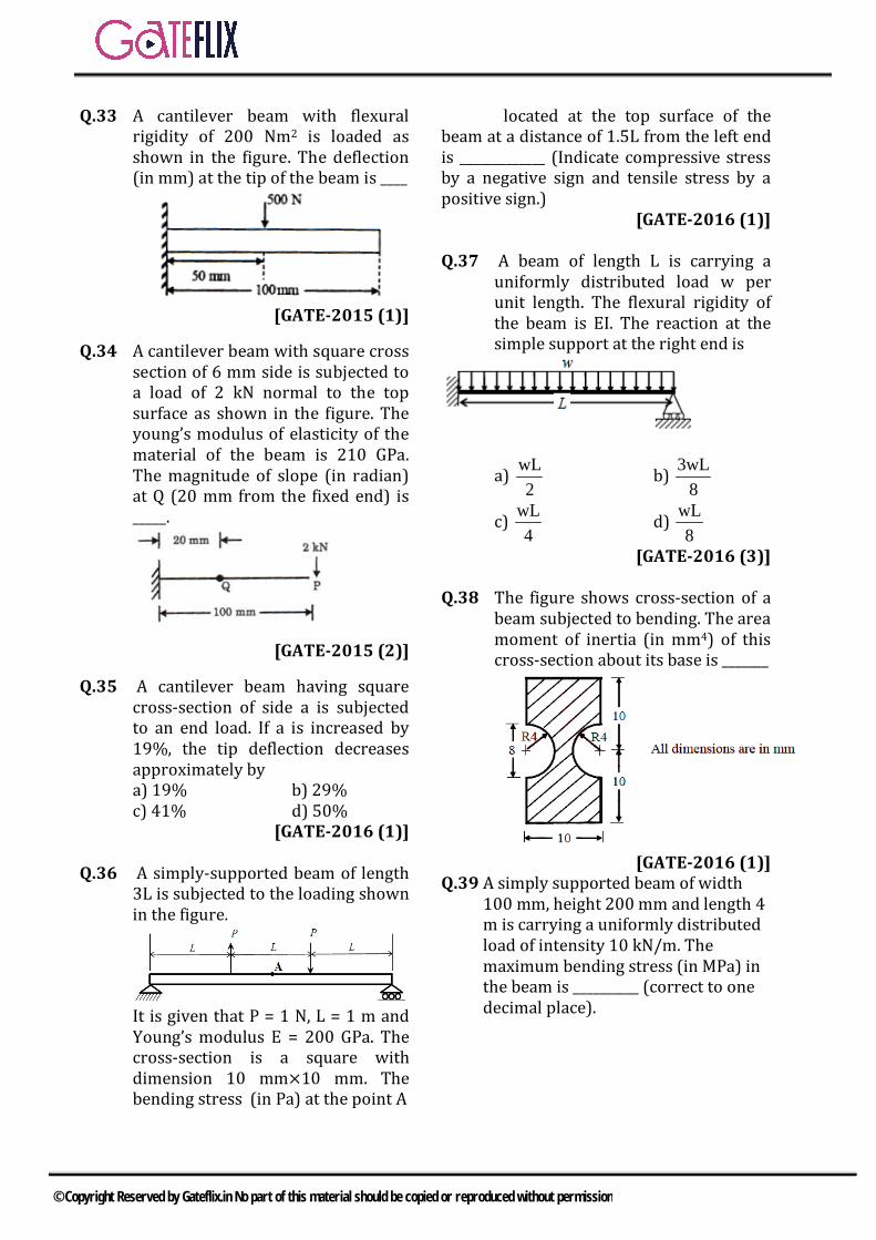
Q.33 A cantilever beam with flexural rigidity of 200 Nm2 is loaded as shown in the figure. The deflection (in mm) at the tip of the beam is ____
[GATE-2015 (1)]
Q.34 A cantilever beam with square cross section of 6 mm side is subjected to a load of 2 kN normal to the top surface as shown in the figure. The young’s modulus of elasticity of the material of the beam is 210 GPa. The magnitude of slope (in radian) at Q (20 mm from the fixed end) is _____.
[GATE-2015 (2)]
Q.35 A cantilever beam having square cross-section of side a is subjected to an end load. If a is increased by 19%, the tip deflection decreases approximately by a) 19% b) 29% c) 41% d) 50%
[GATE-2016 (1)]
Q.36 A simply-supported beam of length 3L is subjected to the loading shown in the figure.
It is given that P = 1 N, L = 1 m and Young’s modulus E = 200 GPa. The cross-section is a square with dimension 10 mm×10 mm. The bending stress (in Pa) at the point A
located at the top surface of the beam at a distance of 1.5L from the left end is _____________ (Indicate compressive stress by a negative sign and tensile stress by a positive sign.)
[GATE-2016 (1)] Q.37 A beam of length L is carrying a
uniformly distributed load w per unit length. The flexural rigidity of the beam is EI. The reaction at the simple support at the right end is
a) wL2
b) 3wL
8
c) wL4
d) wL8
[GATE-2016 (3)] Q.38 The figure shows cross-section of a
beam subjected to bending. The area moment of inertia (in mm4) of this cross-section about its base is _______
[GATE-2016 (1)]
Q.39 A simply supported beam of width 100 mm, height 200 mm and length 4 m is carrying a uniformly distributed load of intensity 10 kN/m. The maximum bending stress (in MPa) in the beam is __________ (correct to one decimal place).
© Copyright Reserved by Gateflix.in No part of this material should be copied or reproduced without permission

[GATE-2018 (1)]
© Copyright Reserved by Gateflix.in No part of this material should be copied or reproduced without permission

1 2 3 4 5 6 7 8 9 10 11 12 13 14 (d) (d) (b) (a) (a) (a) (a) (b) 6.75 (a) (b) (a) (a) (b) 15 16 17 18 19 20 21 22 23 24 25 26 27 28 (d) (d) (d) (b) (c) (d) (c) (b) (a) (b) (d) (a)
(b)
29 30 31 32 33 34 35 36 37 38 39 (a) (a) (c) (d) 0.25 0.16 (d) 0 (b) 1875 30
ANSWER KEY:
© Copyright Reserved by Gateflix.in No part of this material should be copied or reproduced without permission

Q.1 (d)
Q.2 (d) We know that, the simplest form of the simply supported beams is the beam supported on rollers at ends. The simply supported beam and the FBD are shown in the figure.
Where, RA and RB are the reactions acting at the ends of the beam. In equilibrium condition of forces, P = RA + RB ...(i) Taking the moment about point A
BLR L P3
× = ×
BPR3
∴ =
From equation (i)
A2PR3
=
Now bending moment at the point of application of the load
2P LM 2PL3 3 9
= =×
Q.3 (b) Let, d = diameter of circular cross-section a = side of square cross-section Since cross sectional area of square and circular cross-section are equal
2 2π d a4
∴ = …(i)
For circular cross-section,
c 4 3
dMMy 32M2σπdI πd64
= = =
Square cross-section
sM.yσ
I=
4 3
aM 6M2a a12
= =
Now, 3
c
s3
32Mσ πd
6Mσa
=
3
332a6πd
=
232 a a6π d d
=
= 32 π π6π 4 4
= × ×
32 π 32 π 124 4 48
= = >
c sσ σ∴ >
Q.4 (a) We know, differential equation of flexure for the beam is,
2 2
2 2
d y d y MEI Mdx dx El
= ⇒ =
Integrating both side
idy l lmdx Mx Cdx El El
= = +∫Again integrating, y =
2
1 2l Mx C x C
El 2
+ +
...(i)
where, y gives the deflection at the given point. It is easily shown from the equation (i), If we increase the
EXPLANATIONS
© Copyright Reserved by Gateflix.in No part of this material should be copied or reproduced without permission

value of E and I, then deflection reduces.
Q.5 (a)
Given : b = 120 mm , h = 750 mm , 3 2
steelE 200 GPa 200 10 N / mm= = ×
W = 120 kN/m, L = 15 m For a simply supported beam subjected to uniformly distributed load, maximum bending moment occurs at the center and is given by
2 2wL 120 15B.M 3375kN m
8 8×
= = = −
Q.6 (a)
For a simply supported beam subjected to uniformly distributed load, maximum deflection occurs at the center and is given by
4
max5 wLδ
384 EI= ×
For rectangular cross section 3 3
8bh 120 750I 42.1875 10 mm412 12
×= = = ×
( )433
max 3 3 8
15 105 120 10δ384 10 200 10 42.1875 10
××= × ×
× × ×
maxδ 93.75mm=
Q.7 (a) Q.8 (b)
First of all we have to make a free body diagram of the given beam.
Where, RA and RC are the reactions acting at points A and C. The point B is a point of contra flexure or point of inflexion or a virtual hinge. The characteristic of
the point of contra flexure is that, about this point moment equal to zero. For span BC, MB = 0
cLR L P2
× = ×
cPR2
=
Also, RA + RC = P
AP PR P2 2
= − =
Now for the bending moment about point A take the moment about point A.
a cLM R 2L P L 02
+ × − × = =
aP 3LM 2L P 02 2
+ × − × =
aM PL / 2= Q.9 None of these options is correct
Given: L=6m, W=1.5kN/m, d= 75mm We know that for a uniformly distributed load, maximum bending moment at the centre is given by,
2 8 2WL 15 10 (6)B.M.
8 8× ×
= =
B.M = 6750 N-m = 6.75 kN–m Q.10 (a)
From the bending equation. bσ My I=
Where M = Bending moment acting at the given section
I = Moment of inertia ( )4π d64
=
Y = Distance from the neutral axis to
the external fibre d2
=
© Copyright Reserved by Gateflix.in No part of this material should be copied or reproduced without permission
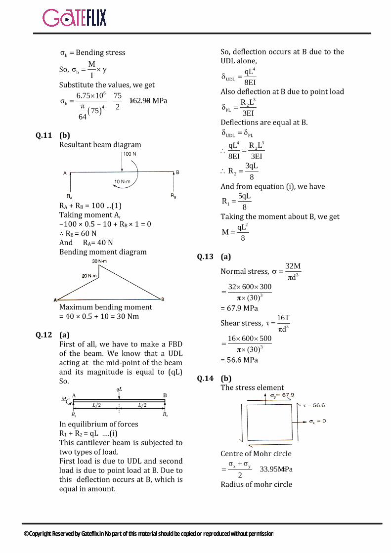
bσ =Bending stress
So, bMσ yI
= ×
Substitute the values, we get
( )
6
b4
6.75 10 75σ 162.98 MPaπ 27564
×= × =
Q.11 (b)
Resultant beam diagram
RA + RB = 100 ...(1) Taking moment A, −100 × 0.5 − 10 + RB × 1 = 0 ∴ RB = 60 N And RA= 40 N Bending moment diagram
Maximum bending moment = 40 × 0.5 + 10 = 30 Nm
Q.12 (a)
First of all, we have to make a FBD of the beam. We know that a UDL acting at the mid-point of the beam and its magnitude is equal to (qL) So.
In equilibrium of forces
R1 + R2 = qL ….(i) This cantilever beam is subjected to two types of load. First load is due to UDL and second load is due to point load at B. Due to this deflection occurs at B, which is equal in amount.
So, deflection occurs at B due to the UDL alone,
4
UDLqL8EI
δ =
Also deflection at B due to point load
3
2PL
R Lδ3EI
=
Deflections are equal at B. UDL PLδ δ=
342R LqL
8EI 3EI∴ =
23qLR
8∴ =
And from equation (i), we have
15qLR
8=
Taking the moment about B, we get
2qLM
8=
Q.13 (a)
Normal stress, 3
32Mπd
σ =
3
32 600 300π (30)× ×
=×
= 67.9 MPa
Shear stress, 3
16Tτπd
=
3
16 600 500π (30)× ×
=×
= 56.6 MPa Q.14 (b)
The stress element
Centre of Mohr circle
x yσ σ33.95MPa
2+
= =
Radius of mohr circle
© Copyright Reserved by Gateflix.in No part of this material should be copied or reproduced without permission
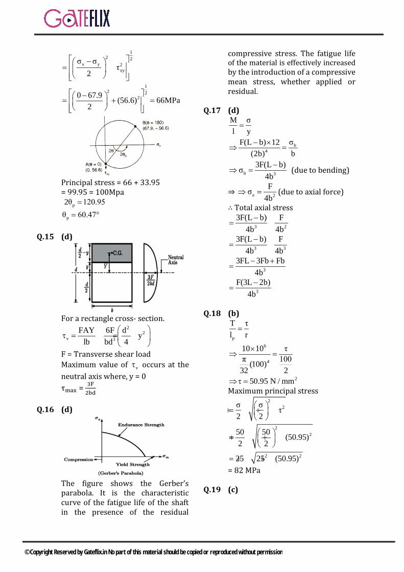
12 2
x y 2xy
σ στ
2
− = +
12 2
20 67.9 (56.6) 66MPa2
− + =
=
Principal stress = 66 + 33.95 = 99.95 = 100Mpa p2θ 120.95=
pθ 60.47°=
Q.15 (d)
For a rectangle cross- section.
22
v 3
FAY 6F d ylb bd 4
τ = = −
F = Transverse shear load Maximum value of vτ occurs at the neutral axis where, y = 0 τmax = 3F
2bd
Q.16 (d)
The figure shows the Gerber’s parabola. It is the characteristic curve of the fatigue life of the shaft in the presence of the residual
compressive stress. The fatigue life of the material is effectively increased by the introduction of a compressive mean stress, whether applied or residual.
Q.17 (d)
M σl y=
b4
σF(L b) 12(2b) b− ×
⇒ =
b 3
3F(L b)σ4b−
⇒ = (due to bending)
⇒ a 2
Fσ4b
⇒ = (due to axial force)
∴ Total axial stress
3 2
3F(L b) F4b 4b−
= +
3 3
3F(L b) F4b 4b−
= +
3
3FL 3Fb Fb4b− +
=
3
F(3L 2b)4b−
=
Q.18 (b)
p
T τl r=
6
4
10 10 τπ 100(100)
32 2
×⇒ =
2 50.95 N / mm⇒τ = Maximum principal stress
2
2σ σ τ2 2
= + +
2250 50 (50.95)
2 2 = + +
2 225 25 (50.95)= + + = 82 MPa
Q.19 (c)
© Copyright Reserved by Gateflix.in No part of this material should be copied or reproduced without permission

Total strain energy stored is given by
L 2 2
0
(Px) dx (PL) 2L22EI
.2EI
+∫
L2 2 32
0
2P P Lx dx2EI EI
= +∫
2 3 2 3P L P LEI 3 EI
= × +
2 3 2 3 2 3P L P L 4 P L3EI EI 3 EI
= + =
Q.20 (d)
For Arm AB: At any section X-X, at a distance x from A
xM Px= −
2
xAB
M dxU2EI
∴ = ∫
L 2
0
( Px) dx2EI−
= ∫
L2 3 2 3
AB0
P x P LU2EI 3 6EI
= =
For Arm BC:
At any section Y-Y at a distance y from B,
yM PL=
2
yBC
M dyU
2EI∴ = ∫
L 2
0
(PL) dy2EI
= ∫
2 2 2 3
LBC 0
P L P LU (y)2EI 2EI
= =
Total strain energy stored in the frame of two arm
AB BCU U U= + 2 3 2 3P L P LU
6EI 2EI= +
2 34P L
6EI=
Therefore, vertical deflection of A is 2 3
AU 4P LδP P 6EI
∂ ∂= = ∂ ∂
( )3
2A
4Lδ P6EI P
∂⇒ =
∂
34L (2P)6EI
=
3
A4PLδ3EI
=
Q.21 (c)
A CR R 6000N+ =
Taking moment about A
© Copyright Reserved by Gateflix.in No part of this material should be copied or reproduced without permission

C6000 3 R 4 0× − × =
CR 4500N⇒ = AR 1500N=
Taking any section at x m from A Shear force =1500-3000(x-2) And maximum bending moment occurs where shear force = 0 ⇒ 1500 – 3000(x-2) = 0 x =2.5m
or 2500 mm from A Q.22 (b)
Maximum bending moment 2
max3000(BM) 1500 (x 2)
2= ×− −
at x = 2.5 21500 2.5 1500(0.5)= × −
=3375 N.m Bending stress,
Mz
σ =
21Z bd6
=
2 9
6 337530 100 10−
×× ×
σ = 6 267.5 10 N / m 67.5MPa= × =
Q.23 (a)
First of all we have to make a free body diagram of the given beam
Here RP and RQ are the reaction forces acting at P and Q For equilibrium of forces on the beam,
RP + PQ = 0 Taking the moment about the point P,
Q QR 1 1 R 1kNm× = ⇒ =
From equation (i), P QR R 1kNm= − = −
Q.24 (b)
Let, b=width of the base of triangle ABD BD=t= thickness of cantilever beam
From similarity of triangles b / 2 h
l x= let OE = h
bxh2l
= ...(i)
Now from figure (ii), For a rectangular cross section.
3 3 2(2h)t bx t bxtl 212 2l 12 12l
= = × × =
From equation (i) Q.25 (d) Q.26 (a) Q.27 (0.064 to 0.067)
P mg 0.5 9.81 4.905N= = × = L = 0.01 m
nf 100Hz=
n nω 2πf 628rad / s= =
nkωm
=
2 2nOr k m 0.5 (6 28)×= ω =
= 197192 N/m
3PL
3EIδ =
3
P 3EIδ L
⇒ =
3P LOr EIδ 3
= ×
© Copyright Reserved by Gateflix.in No part of this material should be copied or reproduced without permission

3(0=19 .07 93
2 1)1 ×
EI = 0.06573 Nm2 Q.28 (b)
2
1PLθ2EI
=
2
2ML PLθEI 2EI
= =
By superposition,
2
1 2PLθ θ θEI
= + =
Q.29 (a)
2
2 2wxy (x 6L 4Lx)24EI
= + −
and 4
maxwLδ8EI
=
Q.30 (a)
max 2 2
3 P 3P Pτ 0.752 A 4h h
= = =
maxPL P 50hM 12.5Ph4 4
×= = =
2 3bh hZ6 3
= =
maxmax 3
M 12.5Ph 3σZ h
×= =
2
P37.5h
=
max
max
τ 0.75 0.02σ 37.5
∴ = =
Q.31 (c)
Deflection due to load 3PL ( ve)
3EI= −
Deflection due to moment ( ) 22 P L x LML ( ve)
2EI 2EI−
= = +
p Mδ δ 0+ =
( ) 2 3P L x L PL2EI 3EI−
∴ =
Or L x L2 3−
=
Or 3L – 3x = 2L
Or Lx or 0.33L3
=
Q.32 (d)
Bending moment in section AB M = - Px
M xP
∂= −
∂
Bending moment in section BC: M = −PL
M LP
∂= −
∂
( )( )
( )( )
L
0A L
0
Px x dx1δEI
PL L dx
− − +
= − −
∫
∫
L L
2 2A
0 0
Pδ x dx L dxEI
= +
∫ ∫
3 33P L 4PLL
EI 3 3EI
= + =
© Copyright Reserved by Gateflix.in No part of this material should be copied or reproduced without permission
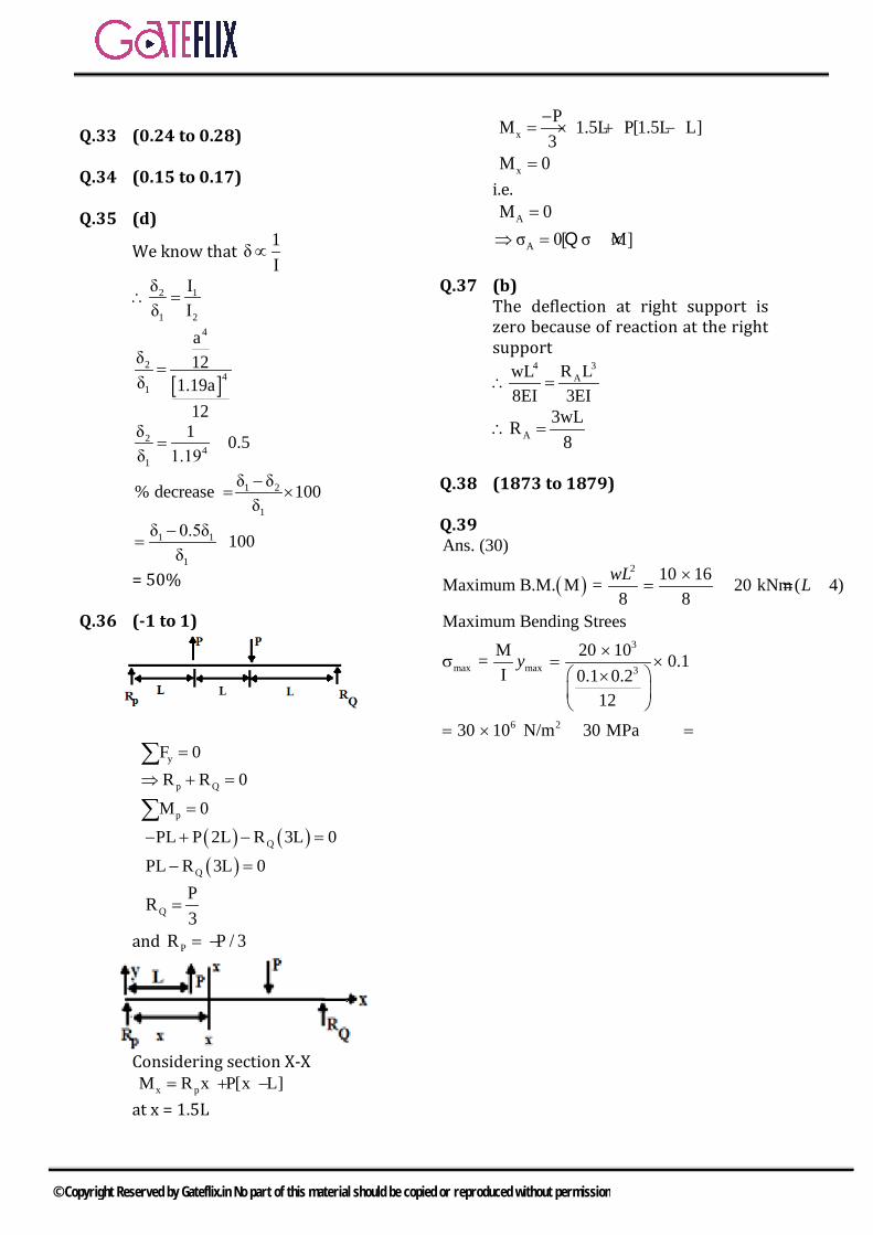
Q.33 (0.24 to 0.28) Q.34 (0.15 to 0.17) Q.35 (d)
We know that 1δI
∝
2 1
1 2
δ Iδ I
∴ =
[ ]
4
24
1
aδ 12δ 1.19a
12
=
24
1
δ 1 0.5δ 1.19
= =
1 2
1
% decrease δ δ 100δ
=−
×
1 1
1
δ 0.5δ 100δ−
= ×
= 50% Q.36 (-1 to 1)
yF 0=∑
p QR R 0⇒ + =
pM 0=∑ ( ) ( )QPL P 2L R 3L 0− + − = ( )QPL R 3L 0− =
QPR3
=
and PR P / 3= −
Considering section X-X x pM R x P[x L]= + − at x = 1.5L
xPM 1.5L P[1.5L L]
3−
= × + −
xM 0= i.e. AM 0=
Aσ 0[ σ M]⇒ = ∝Q Q.37 (b)
The deflection at right support is zero because of reaction at the right support
34AR LwL
8EI 3EI∴ =
A3wLR
8∴ =
Q.38 (1873 to 1879) Q.39
( )2
3
max max 3
6 2
Ans. (30)10 16Maximum B.M. M = 20 kNm ( 4)
8 8Maximum Bending Strees
M 20 10 = 0.1I 0.1 0.2
12
30 10 N/m 30 MPa
wL L
y
= = =
=
= =
© Copyright Reserved by Gateflix.in No part of this material should be copied or reproduced without permission

5.1 PURE TORSION
A component is said to be under pure torsion when two equal and opposite couple are subjected in a plane perpendicular to axis of the component.
Fig. pure torsion
1. TORSION EQUATIONLet us consider a shaft under the pure torsion T as shown in the fig. the angle of twist at the free end is θ and maximum shear angle is ɸ. Radius of the shaft is R and length of the shaft is l.
Figure: Twist deformation of a torque circular shaft. Deformations and rotations greatly exaggerated for visualization convenience.
From the figure it is cleared under pure torsion shear angle does not change with length of the shaft and it changes with the radius of the shaft under the same value of the torsion. But angle of twist does not
change with radius and it change with respect to length of the shaft. So Shear angle is directly proportional to
radius of the shaft but independent fromthe length of the shaft.
Angle of twist is directly proportional tolength of the shaft but independent fromthe radius of the shaft.
In triangle ABB’,
Shear angle at maximum radius is given by BB' RθtanL L
∅ = ∅ = =
Shear strain RθγL
=
So shear strain is directly proportional to radius of the shaft. As per Hook’s law, up to elastic limit
Shear stress maxGRθτ Gγ
L= =
maxτ GθR L
=
Where G = Modulus of rigidity in MPa. So maxτ γ r∝ ∝
maxτ τR r
=
Where, r is radius of the same shaft other than the extreme fiber of the shaft. The shear stress equation (Torsion equation) can be given by
maxτT GθJ R L= =
5 PURE TORSION
© Copyright Reserved by Gateflix.in No part of this material should be copied or reproduced without permission
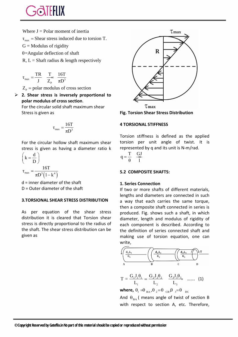
max
Where J = Polar moment of inertiaShear stress induced due to torsion T.
G = Modulus of rigidity=Angular deflection of shaft
R, L = Shaft radius & length respecti y
τ
vel
=
θ
max 3P
TR T 16TτJ Z πD
= = =
PZ polar modulus of cross section= 2. Shear stress is inversely proportional to
polar modulus of cross section. For the circular solid shaft maximum shear Stress is given as
max 3
16TτπD
=
For the circular hollow shaft maximum shear stress is given as having a diameter ratio k
dkD
=
( )max 3 4
16TτπD 1 k
=−
d = inner diameter of the shaft D = Outer diameter of the shaft 3.TORSIONAL SHEAR STRESS DISTRIBUTION As per equation of the shear stress distribution it is cleared that Torsion shear stress is directly proportional to the radius of the shaft. The shear stress distribution can be given as
Fig. Torsion Shear Stress Distribution 4 TORSIONAL STIFFNESS Torsion stiffness is defined as the applied torsion per unit angle of twist. It is represented by q and its unit is N-m/rad.
T GJqθ l
= =
5.2 COMPOSITE SHAFTS: 1. Series Connection If two or more shafts of different materials, lengths and diameters are connected in such a way that each carries the same torque, then a composite shaft connected in series is produced. Fig. shows such a shaft, in which diameter, length and modulus of rigidity of each component is described. According to the definition of series connected shaft and making use of torsion equation, one can write,
3 3 31 1 1 2 2 2
1 2 3
G J θG J θ G J θT =L L L
= = ……. (1)
where, CB DC, ,1 ΒΑ 2 3θ =θ θ = θ θ = θ And ΒΑθ ( means angle of twist of section B with respect to section A, etc. Therefore,
© Copyright Reserved by Gateflix.in No part of this material should be copied or reproduced without permission

angle of twist of section C with respect to A. i.e. DΑ 1 2 3θ = θ + θ + θ The ratio of the torque to the angle of twist, ( T/ θ ) is defined as spring constant. Thus the spring constant of the series connected system will be ACT/ ,θ whereas respective spring constants of components will be
1 2 3T/ , T/ and T/θ θ θ . If the spring constants are denoted by k1. k2, and k3 respectively, then from Equation.
AD1 2 3
ΑD
1 2 3
1 2 3
T T Tθk k k
1 1 1orT k k k
1 1 1 1i.e.k k k k
= + +
θ= + +
= + +
where k is the spring constant of composite shaft, or the equivalent spring constant. The units of k are N-m/radian or N-mm/radian. Torsional shear Stress produced in member 1 is given by
11 3
1 1
T 16TτZ πd
= =
Torsional shear Stress produced in member 2 is given by
22 3
2 2
T 16TτZ πd
= =
Torsional Shear Stress produced in member 3 is given by
33 3
3 3
T 16TτZ πd
= =
2. Statically Indeterminate Torsion Members
Or Parallel Connection
A parallel connected composite shaft system is obtained if two or more shafts are connected together such that the applied torque is changed between them. Such a system is statically indeterminate because in addition to equation of equilibrium,
relationship between the deformations or angles of twist will also have to be used. Figure shows a composite shaft made up of parts AB and BC. The shaft is rigidly held at sections A and C and a torque T is applied at section B when elements 1 and 2 are rigidly connected together. If the torques carried by components 1 and 2 are T1 and T2 respectively, then from equation of equilibrium.
1 2T T T --------- (4)+ =
This equation by itself will not give the values of T1 and T2 and hence stresses or angles of twist in two parts cannot be calculated. Since section 8 is common to both parts AB and BC,
BA BC 1 2θ θ θ θ ------(5)or∴ = = = 0
1 1 2 2
1 1 2 2
T L T I ------- (6)G J G J
=
OR
Simultaneous solution of Equation(4 ) and (6) will yield the values of T1 and T2. If Equation(4) is divided by θ .
( )
1 2
1 2
T TT
or k = k k ---------- 7
= +θ θ θ
+ Where, k is the spring constant of parallel connected shaft, and k1 and k2, are the spring constants of respective components. Note : One obvious fact from Equation( 3 ) and ( 7 ) may now be noted that the spring constant of a series connected system is less than the spring constant of each component shaft, whereas the spring constant of a
© Copyright Reserved by Gateflix.in No part of this material should be copied or reproduced without permission
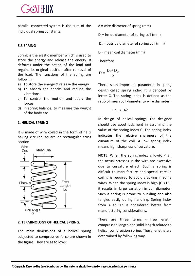
parallel connected system is the sum of the individual spring constants.
5.3 SPRING Spring is the elastic member which is used to store the energy and release the energy. It deforms under the action of the load and regains its original position after removal of the load. The functions of the spring are following: a) To store the energy & release the energy b) To absorb the shocks and reduce the
vibrations. c) To control the motion and apply the
forces d) In spring balance, to measure the weight
of the body etc. 1. HELICAL SPRING It is made of wire coiled in the form of helix having circular, square or rectangular cross section
2. TERMINOLOGY OF HELICAL SPRING:
The main dimensions of a helical spring subjected to compressive force are shown in the figure. They are as follows:
d = wire diameter of spring (mm)
Di = inside diameter of spring coil (mm)
Do = outside diameter of spring coil (mm)
D = mean coil diameter (mm)
Therefore
ODi + DD =2
There is an important parameter in spring design called spring index. It is denoted by letter C. The spring index is defined as the ratio of mean coil diameter to wire diameter.
Or C = D/d
In design of helical springs, the designer should use good judgment in assuming the value of the spring index C. The spring index indicates the relative sharpness of the curvature of the coil. A low spring index means high sharpness of curvature.
NOTE: When the spring index is low(C < 3), the actual stresses in the wire are excessive due to curvature effect. Such a spring is difficult to manufacture and special care in coiling is required to avoid cracking in some wires. When the spring index is high (C >15), it results in large variation in coil diameter. Such a spring is prone to buckling and also tangles easily during handling. Spring index from 4 to 12 is considered better from manufacturing considerations.
There are three terms - free length, compressed length and solid length related to helical compression spring. These lengths are determined by following way
© Copyright Reserved by Gateflix.in No part of this material should be copied or reproduced without permission
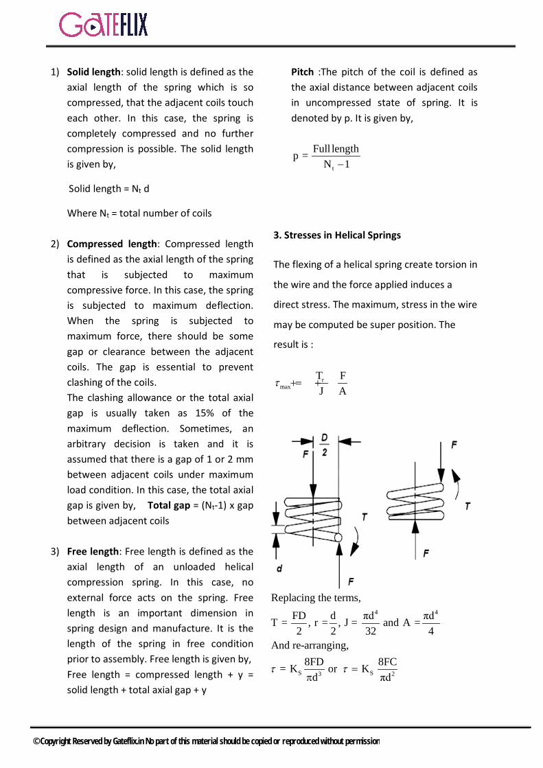
1) Solid length: solid length is defined as the axial length of the spring which is so compressed, that the adjacent coils touch each other. In this case, the spring is completely compressed and no further compression is possible. The solid length is given by,
Solid length = Nt d
Where Nt = total number of coils
2) Compressed length: Compressed length is defined as the axial length of the spring that is subjected to maximum compressive force. In this case, the spring is subjected to maximum deflection. When the spring is subjected to maximum force, there should be some gap or clearance between the adjacent coils. The gap is essential to prevent clashing of the coils. The clashing allowance or the total axial gap is usually taken as 15% of the maximum deflection. Sometimes, an arbitrary decision is taken and it is assumed that there is a gap of 1 or 2 mm between adjacent coils under maximum load condition. In this case, the total axial gap is given by, Total gap = (Nt-1) x gap between adjacent coils
3) Free length: Free length is defined as the axial length of an unloaded helical compression spring. In this case, no external force acts on the spring. Free length is an important dimension in spring design and manufacture. It is the length of the spring in free condition prior to assembly. Free length is given by, Free length = compressed length + y = solid length + total axial gap + y
Pitch :The pitch of the coil is defined as the axial distance between adjacent coils in uncompressed state of spring. It is denoted by p. It is given by,
t
Full lengthp =N 1−
3. Stresses in Helical Springs
The flexing of a helical spring create torsion in
the wire and the force applied induces a
direct stress. The maximum, stress in the wire
may be computed be super position. The
result is :
rmax
T FJ A
τ = + +
4 4
S S3 2
Replacing the terms,FD d πd πdT = , r = , J = and A =2 2 32 4
And re-arranging,8FD 8FC= K or K
d πdτ τ =
π
© Copyright Reserved by Gateflix.in No part of this material should be copied or reproduced without permission
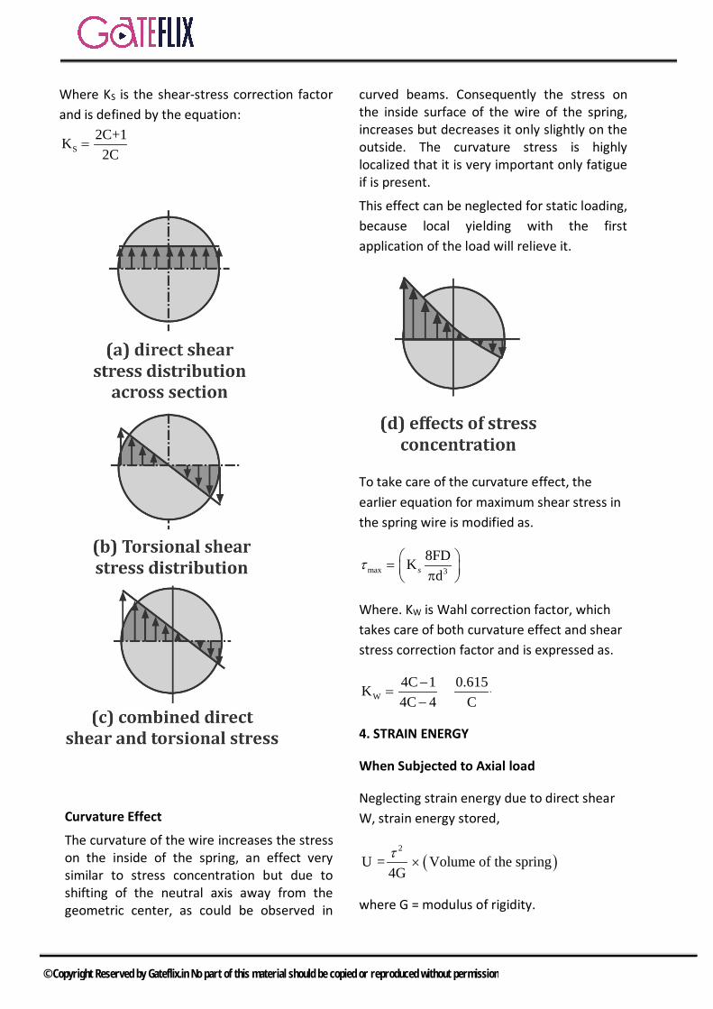
Where KS is the shear-stress correction factor and is defined by the equation:
S2C+1K2C
=
Curvature Effect
The curvature of the wire increases the stress on the inside of the spring, an effect very similar to stress concentration but due to shifting of the neutral axis away from the geometric center, as could be observed in
curved beams. Consequently the stress on the inside surface of the wire of the spring, increases but decreases it only slightly on the outside. The curvature stress is highly localized that it is very important only fatigue if is present.
This effect can be neglected for static loading, because local yielding with the first application of the load will relieve it.
To take care of the curvature effect, the earlier equation for maximum shear stress in the spring wire is modified as.
max 3
8FDKd
= π sτ
Where. KW is Wahl correction factor, which takes care of both curvature effect and shear stress correction factor and is expressed as.
W4C 1 0.615K4C 4 C
−= +
−
4. STRAIN ENERGY
When Subjected to Axial load
Neglecting strain energy due to direct shear W, strain energy stored,
( )2
U = Volume of the spring4Gτ
where G = modulus of rigidity.
© Copyright Reserved by Gateflix.in No part of this material should be copied or reproduced without permission
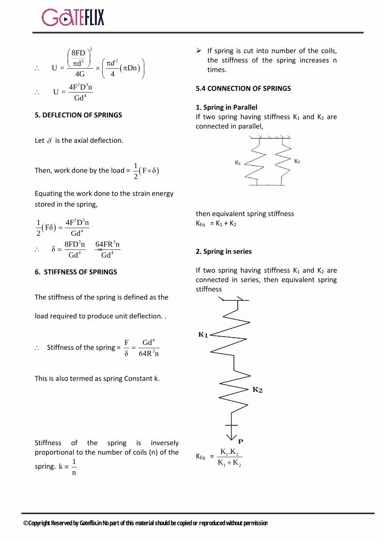
( )
2
23
2 3
4
8FDdU = Dn4G 4
4F D nU =Gd
ππ ∴ π
∴
d
5. DEFLECTION OF SPRINGS
Let δ is the axial deflection.
Then, work done by the load = ( )1 F δ2
Equating the work done to the strain energy stored in the spring,
( )2 3
4
3 3
4 4
1 4F D nFδ2 Gd
8FD n 64FR nδGd Gd
=
∴ = =
6. STIFFNESS OF SPRINGS
The stiffness of the spring is defined as the
load required to produce unit deflection. .
∴ Stiffness of the spring = 4
3
F Gdδ 64R n=
This is also termed as spring Constant k.
Stiffness of the spring is inversely proportional to the number of coils (n) of the
spring. 1kn
∝
If spring is cut into number of the coils, the stiffness of the spring increases n times.
5.4 CONNECTION OF SPRINGS 1. Spring in Parallel If two spring having stiffness K1 and K2 are connected in parallel,
then equivalent spring stiffness KEq = K1 + K2
2. Spring in series If two spring having stiffness K1 and K2 are connected in series, then equivalent spring stiffness
KEq = 1 2
1 2
K .KK K+
© Copyright Reserved by Gateflix.in No part of this material should be copied or reproduced without permission

Q.1 Maximum shear stress developed on the surface of a solid circular shaft under pure torsion is 240 MPa. If the shaft diameter is doubled then the maximum shear stress developed corresponding to the same torque will be a) 120 MPa b) 60 MPac) 30 MPa d) 15 MPa
[GATE-2003]
Q.2 A torque of 10 Nm is transmitted through a stepped shaft as shown in figure. The torsional stiffness of individual sections of length MN, NO and OP are 20 Nm/rad, 30 Nm/rad and 60 Nm/rad respectively. The angular deflection between the ends M and P of the shaft is
a) 0.5 rad b) 1.0 radc) 5.0 rad d)10.0 rad
[GATE-2004]
Q.3 A solid circular shaft of 60 mm diameter transmits a torque of 1600 Nm. The value of maximum shear stress developed is a) 37.72 MPa b) 47.72 MPac) 57.72 MPa d) 67.72 MPa
[GATE-2004]
Q.4 Two shafts AB and BC, of equal length and diameters d and 2d, are made of the same material. They are joined at B through a shaft coupling, while the ends A and C
are built-in (cantilevered). A twisting moment T is applied to the coupling. If TA and TC represent the twisting moments at the ends A and C , respectively, then
a) TC = TA b) TC = 8TAc)TC = 16TA d) TA = 16TC
[GATE-2005]
Q.5 For a circular shaft of diameter d subjected to torque T, the maximum value of the shear stress is
a) 3
64Tπd
b) 3
32Tπd
c) 3
16Tπd
d) 3
8Tπd
[GATE-2006]
Q.6 A solid shaft of diameter d and length L is fixed at both the ends. A torque, T0 is applied at a distance L/4 from the left end as shown in the figure given below
The maximum shear stress in the shaft is
a) o3
16Tπd
b) o3
12Tπd
c) o3
8Tπd
d) o3
4Tπd
[GATE-2009]
GATE QUESTIONS
© Copyright Reserved by Gateflix.in No part of this material should be copied or reproduced without permission
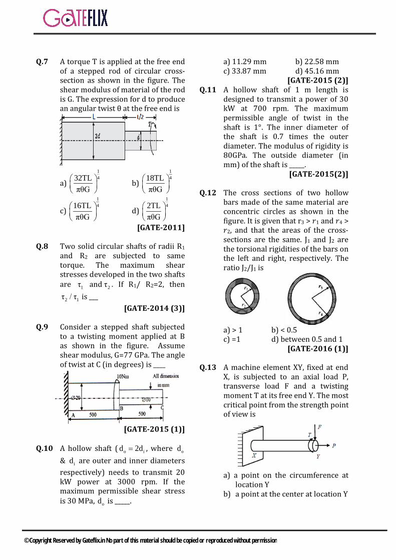
Q.7 A torque T is applied at the free end
of a stepped rod of circular cross-section as shown in the figure. The shear modulus of material of the rod is G. The expression for d to produce an angular twist θ at the free end is
a)
1432TL
πθG
b) 1418TL
πθG
c)
1416TL
πθG
d) 142TL
πθG
[GATE-2011] Q.8 Two solid circular shafts of radii R1
and R2 are subjected to same torque. The maximum shear stresses developed in the two shafts are 1τ and 2τ . If R1/ R2=2, then
2 1τ / τ is ___ [GATE-2014 (3)]
Q.9 Consider a stepped shaft subjected
to a twisting moment applied at B as shown in the figure. Assume shear modulus, G=77 GPa. The angle of twist at C (in degrees) is ____
[GATE-2015 (1)]
Q.10 A hollow shaft ( o id 2d= , where od
& id are outer and inner diameters respectively) needs to transmit 20 kW power at 3000 rpm. If the maximum permissible shear stress is 30 MPa, od is _____.
a) 11.29 mm b) 22.58 mm c) 33.87 mm d) 45.16 mm
[GATE-2015 (2)] Q.11 A hollow shaft of 1 m length is
designed to transmit a power of 30 kW at 700 rpm. The maximum permissible angle of twist in the shaft is 1°. The inner diameter of the shaft is 0.7 times the outer diameter. The modulus of rigidity is 80GPa. The outside diameter (in mm) of the shaft is _____.
[GATE-2015(2)]
Q.12 The cross sections of two hollow bars made of the same material are concentric circles as shown in the figure. It is given that r3 > 𝑟𝑟1 and 𝑟𝑟4 > 𝑟𝑟2, and that the areas of the cross-sections are the same. J1 and J2 are the torsional rigidities of the bars on the left and right, respectively. The ratio J2/J1 is
a) > 1 b) < 0.5 c) =1 d) between 0.5 and 1
[GATE-2016 (1)]
Q.13 A machine element XY, fixed at end X, is subjected to an axial load P, transverse load F and a twisting moment T at its free end Y. The most critical point from the strength point of view is
a) a point on the circumference at
location Y b) a point at the center at location Y
© Copyright Reserved by Gateflix.in No part of this material should be copied or reproduced without permission
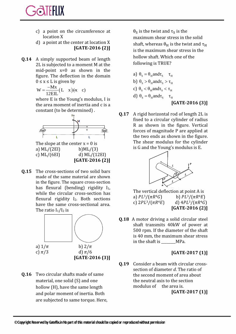
c) a point on the circumference at location X
d) a point at the center at location X [GATE-2016 (2)]
Q.14 A simply supported beam of length
2L is subjected to a moment M at the mid-point x=0 as shown in the figure. The deflection in the domain 0 ≤ x ≤ L is given by
( )MxW L x (x c)12EIL−
= − +
where E is the Young’s modulus, I is the area moment of inertia and c is a constant (to be determined) .
The slope at the center x = 0 is a) ML/(2EI) b)ML/(3) c) ML/(6EI) d) ML/(12EI)
[GATE-2016 (2)] Q.15 The cross-sections of two solid bars
made of the same material are shown in the figure. The square cross-section has flexural (bending) rigidity I1, while the circular cross-section has flexural rigidity I2. Both sections have the same cross-sectional area. The ratio I1/I2 is
a) 1/𝜋𝜋 b) 2/𝜋𝜋 c) 𝜋𝜋/3 d) 𝜋𝜋/6
[GATE-2016 (3)] Q.16 Two circular shafts made of same material, one solid (S) and one hollow (H), have the same length and polar moment of inertia. Both are subjected to same torque. Here,
θS is the twist and τS is the maximum shear stress in the solid shaft, whereas θH is the twist and τH is the maximum shear stress in the hollow shaft. Which one of the following is TRUE?
a) S H S Hθ θ andτ τ= = b) S H S Hθ θ andτ τ> > c) S H S Hθ θ andτ τ< < d) S H S Hθ θ andτ τ= <
[GATE-2016 (3)] Q.17 A rigid horizontal rod of length 2L is
fixed to a circular cylinder of radius R as shown in the figure. Vertical forces of magnitude P are applied at the two ends as shown in the figure. The shear modulus for the cylinder is G and the Young’s modulus is E.
The vertical deflection at point A is a) 𝑃𝑃𝑃𝑃3/(𝜋𝜋𝜋𝜋4𝐺𝐺) b) 𝑃𝑃𝑃𝑃3/(𝜋𝜋𝜋𝜋4𝐸𝐸) c) 2𝑃𝑃𝑃𝑃3/(𝜋𝜋𝜋𝜋4𝐸𝐸) d) 4𝑃𝑃𝑃𝑃3/(𝜋𝜋𝜋𝜋4𝐺𝐺)
[GATE-2016 (2)]
Q.18 A motor driving a solid circular steel shaft transmits 40kW of power at 500 rpm. If the diameter of the shaft is 40 mm, the maximum shear stress in the shaft is ________MPa.
[GATE-2017 (1)] Q.19 Consider a beam with circular cross- section of diameter d. The ratio of the second moment of area about the neutral axis to the section modulus of the area is.
[GATE-2017 (1)]
© Copyright Reserved by Gateflix.in No part of this material should be copied or reproduced without permission
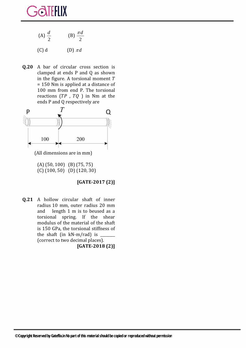
(A) 2d (B)
2dπ
(C) d (D) dπ
Q.20 A bar of circular cross section is clamped at ends P and Q as shown in the figure. A torsional moment 𝑇𝑇 = 150 Nm is applied at a distance of 100 mm from end P. The torsional reactions (𝑇𝑇𝑃𝑃 , 𝑇𝑇𝑄𝑄 ) in Nm at the ends P and Q respectively are
(All dimensions are in mm) (A) (50, 100) (B) (75, 75) (C) (100, 50) (D) (120, 30)
[GATE-2017 (2)] Q.21 A hollow circular shaft of inner radius 10 mm, outer radius 20 mm and length 1 m is to beused as a torsional spring. If the shear modulus of the material of the shaft is 150 GPa, the torsional stiffness of the shaft (in kN-m/rad) is ________ (correct to two decimal places).
[GATE-2018 (2)]
© Copyright Reserved by Gateflix.in No part of this material should be copied or reproduced without permission
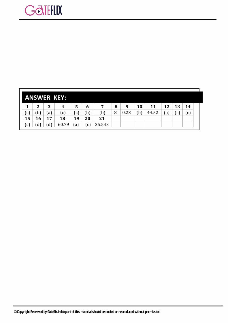
1 2 3 4 5 6 7 8 9 10 11 12 13 14 (c) (b) (a) (c) (c) (b) (b) 8 0.23 (b) 44.52 (a) (c) (c) 15 16 17 18 19 20 21 (c) (d) (d) 60.79 (a) (c) 35.543
ANSWER KEY:
© Copyright Reserved by Gateflix.in No part of this material should be copied or reproduced without permission
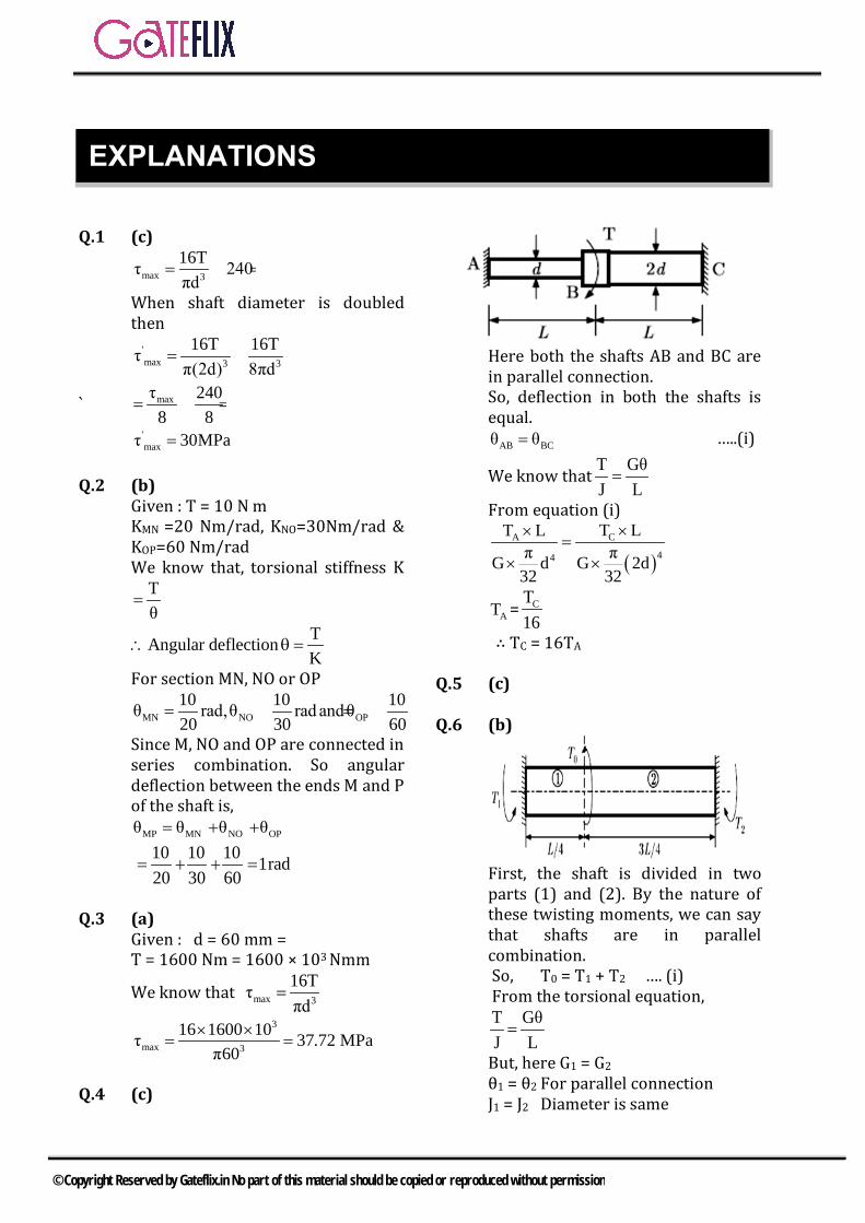
Q.1 (c)
max 3
16Tτ 240πd
= =
When shaft diameter is doubled then
'max 3 3
16T 16Tτπ(2d) 8πd
= =
` maxτ 2408 8
= =
'maxτ 30MPa=
Q.2 (b) Given : T = 10 N m KMN =20 Nm/rad, KNO=30Nm/rad & KOP=60 Nm/rad We know that, torsional stiffness K
Tθ
=
TAngular deflectionK
∴ θ =
For section MN, NO or OP
MN NO OP10 10 10θ rad,θ rad andθ20 30 60
= = =
Since M, NO and OP are connected in series combination. So angular deflection between the ends M and P of the shaft is,
MP MN NO OPθ θ θ θ= + +
10 10 10 1rad20 30 60
= + + =
Q.3 (a) Given : d = 60 mm = T = 1600 Nm = 1600 × 103 Nmm
We know that max 3
16Tτπd
=
3
max 3
16 1600 10τ 37.π
760
2 MPa×==
×
Q.4 (c)
Here both the shafts AB and BC are in parallel connection. So, deflection in both the shafts is equal.
AB BCθ θ= …..(i)
We know that T GθJ L=
From equation (i)
( )CA
44
T LT Lπ πG d G 2d
32 32
××=
× ×
AT = CT16
∴ TC = 16TA
Q.5 (c)
Q.6 (b)
First, the shaft is divided in two parts (1) and (2). By the nature of these twisting moments, we can say that shafts are in parallel combination. So, T0 = T1 + T2 …. (i) From the torsional equation, T GθJ L=
But, here G1 = G2 θ1 = θ2 For parallel connection J1 = J2 Diameter is same
EXPLANATIONS
© Copyright Reserved by Gateflix.in No part of this material should be copied or reproduced without permission

So, T1L1 =T2L2 T1 = 3T2 Now From equation (i), TO = 3T2 + T2 = 4T2
o2T T
4=
And o1T 3T
4=
Here 1 2T T> So, maximum shear stress is developed due to T1, Substitute the values, we get
oo
max 34
3 T 12Td4τ π 2 πdd32
× ==
Q.7 (b)
Here we see that shafts are in series combination. For series combination Total angular twist,
1 2θ θ θ= + … (i) From the torsion equation
τ T Gθr J L= =
TLθGJ
∴ =
Now from equation (i)
( ) ( )4 4
TL TL / 2θ π π2d G d G32 32
= =
On simplifying, we get 1418TLd
πθG =
Q.8 (8)
max 3
2TτπR
= 3
32 1
1 2
τ R (2) 8τ R
= = =
1 2( T T T)= =Q Q.9 (0.23)
Angle of twist at(C)= Angle of twist at(B)
TLGJ
⇒θ =
39 4
10 0.5 32 4.133 10 rad77 10 π 0.02
−× ×⇒ = ×
× × × 00.236⇒θ =
Q.10 (b)
P = Tω 3 2 300020 10 T
60π×
× = ×
∴ T = 63.662 N-m
Now T τJ R=
So, 6
4 ii
63.662 30 10π d(15d )
32
×=
id 11.295mm∴ =
0 id 2d 22.59mm∴ = =
Q.11 (44.52) P = Tω
30 1000 T 2π 70060
× = ××
∴ T = 409.256 N-m
T GθJ L=
9
4 40
409.256 80 10 ππ 1 180(1 0.7 )d
32
×= ×
−
Solving, we get, 0d 44.5213mm=
Q.12 (a)
Given 1 2A A= 2 2 2 22 1 4 3π r r π r r ⇒ − = −
Now 4 44 3
2
4 412 1
πG r rJ 2πJ G r r2
× − =
× −
2 2 2 24 3 4 3
2
2 2 2 212 1 2 1
π r r r rJ 2πJ r r r r2
− + =
− +
1 2 4 2 3 1A A r r r& & r= > >Q
© Copyright Reserved by Gateflix.in No part of this material should be copied or reproduced without permission

2
1
J 1J
∴ >
Q.13 (c)
At the center, shear and torsional stresses are zero.
Q.14 (c) Q.15 (c)
Given: 2
2 πda4
= ------- (1)
1
42
4aI 12πI d
64
= ------ (2)
From equation (1) and (2) 1
2
I πI 3=
Q.16 (d) Q.17 (d)
[ ]T P 2L 2PL= =
( )4
2PL LTLθ πGJ G [2R]32
= =
2
4
4PLπGR
=
3
4
4PLy RπGR
= θ =
Q.18
2 N60π
ω =
PP T. T= ω⇒ =ω
max 3 3
16T 16 P.d d
τ = =π π ω
Q
max 3
16T P. 60d 2 N
τ = ×π π
Q
3
3
16 40 10 60(0.04) 2 500× × ×
=π × π×
max 60.79Mpaτ = Q.19 (a)
N.A
max
Isec tion mod ulusY
=Q &
maxdY for circular cross sec tion.2
=
N.Amax
N.A
I dratio .YI 2
∴ = =
Q.20 (c)
( )( )
( )
1 1 2 2
1 2
1 2
1 2
2 2
2
1
Angular twist at torque must be same.T L T LTL=
GJ GJ GJT ×100 = T ×200
T 2 T 1
150 2Solving2T + T 150
T 50 . .T 100 N.m
T = 100, 50
T T T
N m
θ = =
∴ = −− − − −
+ = = − − − − −
=
∴ =
∴ =
Q.21
( )
9 4 4
Ans. 35.343
Torsionalstiffness =
150 10 0.04 0.0232
135343 Nm/rad = 35.343 kNm/rad
PGIL
π − =
=
© Copyright Reserved by Gateflix.in No part of this material should be copied or reproduced without permission

Q.1 A weighing machine consists of a 2 kg pan resting on a spring. In this condition, with the pan resting on the spring, the length of the spring is 200 mm. When a mass of 20 kg is placed on the pan, the length of the spring becomes 100 mm. For the spring, the un-deformed length L and the spring constant k (stiffness) are a) L = 220 mm, k = 1862 N/mb) L = 210 mm, k = 1960 N/mc) L = 200 mm, k = 1960 N/md) L = 200 mm, k = 2156 N/m
[GATE-2005]
Q.2 A compression spring is made of music wire of 2 mm diameter having a shear strength and shear modulus of 800 MPa and 80 GPa respectively. The mean coil diameter is 20 mm, free length is 40 mm a
the number of active coils is 10. If the mean coil diameter is reduced to 10 mm, the stiffness of the spring is approximately a) decreased by 8 timesb) decreased by 2 timesc) Increased by 2 timesd) increased by 8 times
[GATE-2008]
Q.3 The spring constant of a helical compression spring DOES NOT depend on a) coil diameterb) material strengthc) number of active turnsd) wire diameter
[GATE-2016(1)]
Q.4 A helical compression spring made of wire of circular cross-section is subjected to a compressive load. The maximum shear stress induced in the cross-section of the wire is 24 MPa. For the same compressive load, if both the wire diameter and the mean coil diameter are doubled, the maximum shear stress (in MPa) induced in the cross-section of the wire is _____.
[GATE 2017 (2)]
GATE QUESTIONS
© Copyright Reserved by Gateflix.in No part of this material should be copied or reproduced without permission

1 2 3 4 (b) (d) (b) 6
ANSWER KEY:
© Copyright Reserved by Gateflix.in No part of this material should be copied or reproduced without permission
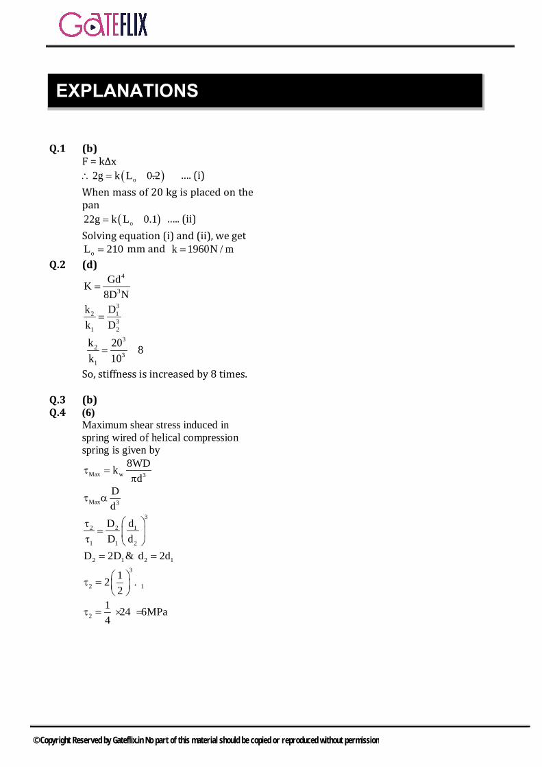
Q.1 (b) F = k∆x
( )o2g k L 0.2∴ = − …. (i)When mass of 20 kg is placed on the pan
( )o22g k L 0.1= − ….. (ii) Solving equation (i) and (ii), we get
oL 210= mm and k 1960N / m= Q.2 (d)
4
3
GdN
K8D
=
32 1
31 2
k Dk D
=
32
31
k 20 8k 10
= =
So, stiffness is increased by 8 times.
Q.3 (b) Q.4 (6)
Maximum shear stress induced in spring wired of helical compression spring is given by
Max w 3
8WDkd
τ =π
Max 3
Dd
τ α
3
2 2 1
1 1 2
D dD d
τ= τ
2 1D 2D= & 2 1d 2d=3
2 112 .2
τ = τ
21 24 6MPa4
τ = × =
EXPLANATIONS
© Copyright Reserved by Gateflix.in No part of this material should be copied or reproduced without permission
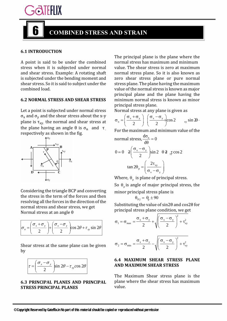
6.1 INTRODUCTION
A point is said to be under the combined stress when it is subjected under normal and shear stress. Example: A rotating shaft is subjected under the bending moment and shear stress. So it is said to subject under the combined load.
6.2 NORMAL STRESS AND SHEAR STRESS
Let a point is subjected under normal stress σx and σy and the shear stress about the x-y plane is τxy. the normal and shear stress at the plane having an angle θ is σn and τ . respectively as shown in the fig.
Considering the triangle BCP and converting the stress in the term of the forces and then resolving all the forces in the direction of the normal stress and shear stress, we get Normal stress at an angle θ
θτθσσσσ
σ 2 sin2 cos22 xy
yxyxn +
−+
+=
Shear stress at the same plane can be given by
θτθσσ
τ 2 os2in 2
cs xyyx −
−=
6.3 PRINCIPAL PLANES AND PRINCIPAL STRESS PRINCIPAL PLANES
The principal plane is the plane where the normal stress has maximum and minimum value. The shear stress is zero at maximum normal stress plane. So it is also known as zero shear stress plane or pure normal stress plane. The plane having the maximum value of the normal stress is known as major principal plane and the plane having the minimum normal stress is known as minor principal stress plane. Normal stress at any plane is given as
x y x yn xycos 2 sin 2
2 2σ +σ σ −σ
σ = + θ+ τ θ
For the maximum and minimum value of the
normal stress, ndσ 0dθ
=
x yxy0 0 2 sin 2 2 cos 2
2σ −σ
= − θ+ τ θ
xyp
x y
2tan 2
τθ = σ −σ
Where, pθ is plane of principal stress. So pθ is angle of major principal stress, the minor principal stress plane is
pP2θ 90= θ ±
Substituting the value of sin2θ and cos2θ for principal stress plane condition, we get
2x y x y 2
1 max xy2 2σ +σ σ −σ
σ = σ = + + τ
2x y x y 2
2 min xy2 2σ +σ σ −σ
σ = σ = − + τ
6.4 MAXIMUM SHEAR STRESS PLANE AND MAXIMUM SHEAR STRESS
The Maximum Shear stress plane is the plane where the shear stress has maximum value.
6 COMBINED STRESS AND STRAIN
© Copyright Reserved by Gateflix.in No part of this material should be copied or reproduced without permission

The shear stress equation can be given as x y
xysin 2 cos 22
σ −σ τ = θ− τ θ
For the maximum shear stress dτ 0dθ
=
x yxy0 2cos 2 2 sin2
2σ −σ
= θ+ τ θ
tan 22x y
sxy
σ σθ
τ −
= −
s2 s1 90θ = θ + Maximum shear stress can be given as
2x y 2
max xy2σ −σ
τ = + + τ
2x y 2
max xy'2
σ −σ τ = − + τ
τmax and τ’max are complementary shear stress. τmax is given by
1 2
maxσ στ
2−
=
6.5 PRINCIPAL STRAIN & SHEAR STRAIN
The normal strain at an angle θ is given by
x y x y xyn
ε ε ε ε γε cos 2θ sin 2θ
2 2 2+ −
= + +
The shear strain at an angle is given by
x y xyε ε γγ sin 2θ cos 2θ2 2 2θ
− = − +
The maximum and minimum strain at the principal plane can be given as
2 2x y x y xy
1,2
ε ε ε ε γε
2 2 2+ −
= ± +
The maximum shear strain is given as ( )max 1 2γ ε ε= − −
6.6 COMBINED BENDING & TORSION Let a shaft of diameter `d` be subjected to bending moment M` and a twisting moment `T` at a section. At any point in the section at radius `r` and at a distance y from the neutral axis, the bending stress is given by
M .yI
σ =
and shear stress is given by
p
T .rI
τ =
Where, I = Moment of Inertia about its NA. 4I d and
64π
=
Polar moment of inertia
4pI d
32π
=
22
1 2, 2 2σ σ σ = ± + τ
2 21 2 3
16, M M Td
σ = ± + π
The maximum shear stresses is given by 1 2
max or2
σ −στ =
2 2max 3
16 M Td
τ = +π
1. Equivalent Bending Moment & Equivalent Torque: Let `Me` be the equivalent bending moment which acting alone produces the maximum tensile stress equal to σ1, as produced by M & T.
© Copyright Reserved by Gateflix.in No part of this material should be copied or reproduced without permission
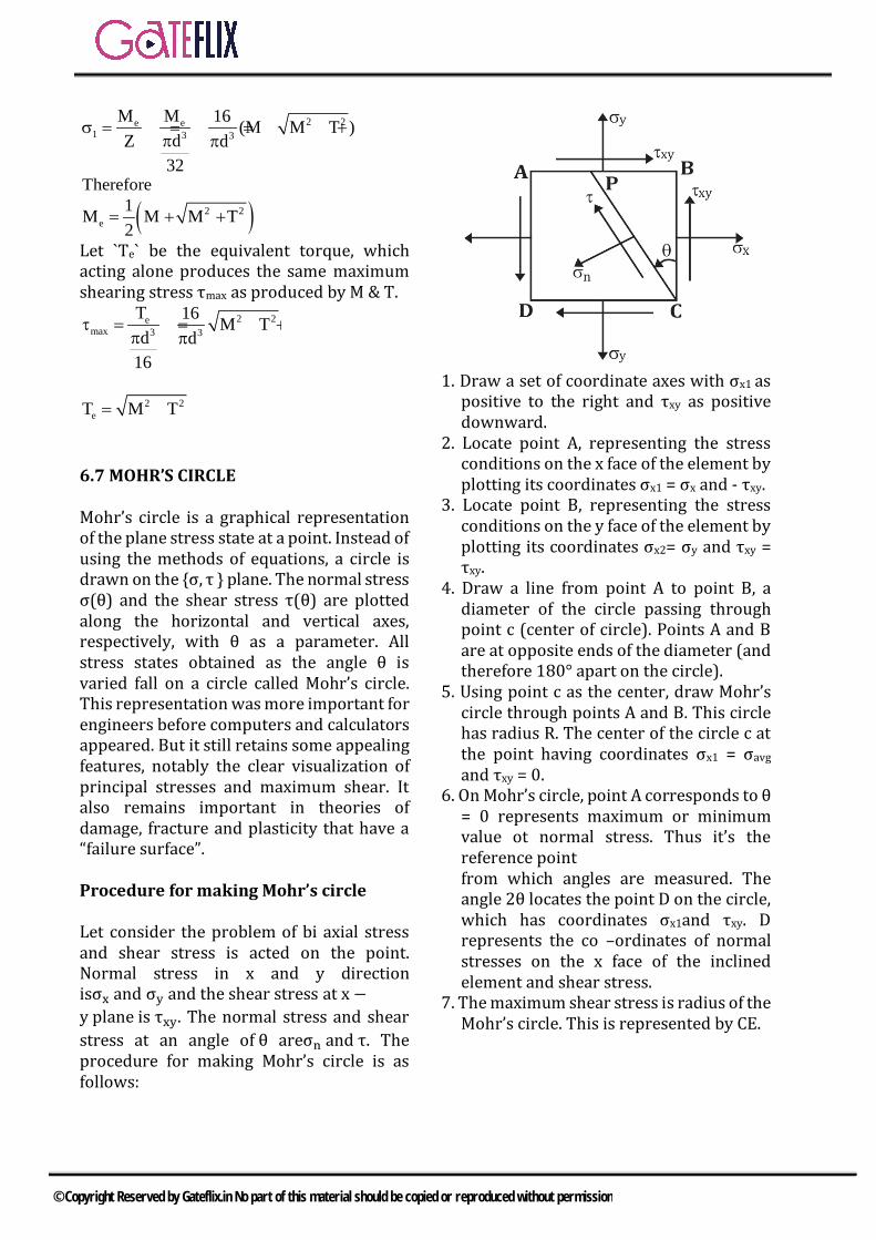
2 2e e1 3 3
M M 16 (M M T )dZ d
32
σ = = = + +π π
Therefore
( )2 2e
1M M M T2
= + +
Let `Te` be the equivalent torque, which acting alone produces the same maximum shearing stress τmax as produced by M & T.
2 2emax 3 3
T 16 M Td d
16
τ = = +π π
2 2
eT M T= + 6.7 MOHR’S CIRCLE Mohr’s circle is a graphical representation of the plane stress state at a point. Instead of using the methods of equations, a circle is drawn on the {σ, τ } plane. The normal stress σ(θ) and the shear stress τ(θ) are plotted along the horizontal and vertical axes, respectively, with θ as a parameter. All stress states obtained as the angle θ is varied fall on a circle called Mohr’s circle. This representation was more important for engineers before computers and calculators appeared. But it still retains some appealing features, notably the clear visualization of principal stresses and maximum shear. It also remains important in theories of damage, fracture and plasticity that have a “failure surface”. Procedure for making Mohr’s circle Let consider the problem of bi axial stress and shear stress is acted on the point. Normal stress in x and y direction isσx and σy and the shear stress at x −y plane is τxy. The normal stress and shear stress at an angle of θ areσn and τ. The procedure for making Mohr’s circle is as follows:
1. Draw a set of coordinate axes with σx1 as
positive to the right and τxy as positive downward.
2. Locate point A, representing the stress conditions on the x face of the element by plotting its coordinates σx1 = σx and - τxy.
3. Locate point B, representing the stress conditions on the y face of the element by plotting its coordinates σx2= σy and τxy = τxy.
4. Draw a line from point A to point B, a diameter of the circle passing through point c (center of circle). Points A and B are at opposite ends of the diameter (and therefore 180° apart on the circle).
5. Using point c as the center, draw Mohr’s circle through points A and B. This circle has radius R. The center of the circle c at the point having coordinates σx1 = σavg and τxy = 0.
6. On Mohr’s circle, point A corresponds to θ = 0 represents maximum or minimum value ot normal stress. Thus it’s the reference point
from which angles are measured. The angle 2θ locates the point D on the circle, which has coordinates σx1and τxy. D represents the co –ordinates of normal stresses on the x face of the inclined element and shear stress.
7. The maximum shear stress is radius of the Mohr’s circle. This is represented by CE.
© Copyright Reserved by Gateflix.in No part of this material should be copied or reproduced without permission

Normal stress on the plane of θ is given as
nσ OP OC CP= = + =
x y x yxycos 2 sin 2
2 2σ +σ σ −σ
+ θ+ τ θ The shear stress on the plane of the θ is given by
x yxysin 2 cos 2
2τ DP
σ −σ θ− τ θ
= =
Major Principal stress and minor principal stress is given by
1 maxσ σ OF OC CF= = = +
1 maxσ σ OG OC CG= = = + Substituting the value of OC, CF, CG, we get
2x y x y 2
1 max xy2 2σ +σ σ −σ
σ = σ = + + τ
2x y x y 2
2 min xy2 2σ +σ σ −σ
σ = σ = − + τ
The maximum shear stress is given by τmax = CE = Radius of the Mohr′scircle
Substituting the value of the radius of the Mohr’s circle
2x y 2
max xy2σ −σ
τ = + + τ
2x y 2
max xy2σ −σ
τ = − + τ
Case (1) A point is subjected under pure torsion due to which shear stress developed at that point is τ.
Case (2) A point is subjected under equal and same nature of the normal stress and shear stress is zero.
So shear stress in this condition is zero. In all the direction, normal stress is same
and of same nature. Mohr’s circle in this case will be a point.
© Copyright Reserved by Gateflix.in No part of this material should be copied or reproduced without permission

Data for Q.1 and 2 is given below. The state of stress at a point "P" in a two dimensional loading is such that the Mohr's circle is a point located at 175 MPa on the positive normal stress axis.
Q.1 The maximum and minimum principal stresses respectively from the Mohr's circle are a) +175 MPa, −175 MPab) +175 MPa, +175 MPac) 0, −175 MPad) 0, 0
[GATE-2003]
Q.2 The directions of maximum and minimum principal stresses at the point "P " from the Mohr's circle are a) 0, 90° b) 90°, 0c) 45c, 135° d) all directions
[GATE-2003]
Q.3 The figure shows the state of stress at a certain point in a stressed body. The magnitudes of normal stresses in x and y directions are 100 MPa and 20 MPa respectively. The radius of Mohr's stress circle representing this state of stress is
a) 120 MPa b) 80 MPac) 60 MPa d) 40 MPa
[GATE-2004]
Q.4 The Mohr's circle of plane stress for a point in a body is shown. The design is to be done on the basis of the maximum shear stress theory for yielding. Then, yielding will just
begin if the designer chooses a ductile material whose yield strength is
a) 45 MPa b) 50 MPac) 90 MPa d) 100 MPa
[GATE-2005]
Q.5 A two dimensional fluid element rotates like a rigid body. At a point within the element, the pressure is 1 unit. Radius of the Mohr's circle, characterizing the state of stress at that point, is a) 0.5 unit b) 0 unitc) 1 unit d) 2 unit
[GATE-2008]
Q.6 The state of stress at a point under plane stress condition is xxσ =40 MPa, yyσ = 100 MPa and τxy = 40 MPa. The radius of the Mohr's circle representing the given state of stress in MPa is a) 40 b) 50c) 60 d)100
[GATE-2012]
Q.7 In a plane stress condition, the components of stress at a point are
x y xyσ 20MPa;σ 80MPa; τ 40MPa= = =
The maximum shear stress (in MPa) at the point is ____ a) 20 b)25 c) 50 d) 100
[GATE-2015(2)]
GATE QUESTIONS
© Copyright Reserved by Gateflix.in No part of this material should be copied or reproduced without permission
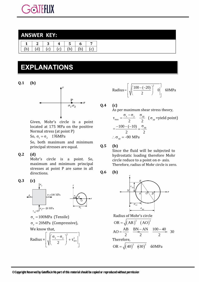
Q.1 (b)
Given, Mohr’s circle is a point located at 175 MPa on the positive Normal stress (at point P) So, 1 2 17 Paσ σ 5M= = So, both maximum and minimum principal stresses are equal.
Q.2 (d) Mohr’s circle is a point. So, maximum and minimum principal stresses at point P are same in all directions.
Q.3 (c)
x 10 aσ 0MP= (Tensile)
yσ 20MPa= (Compressive), We know that,
Radius =2
x y 2XY
σ στ
2
− +
Radius2100 – ( 20) 0 60MPa
2
− = + =
Q.4 (c) As per maximum shear stress theory,
x y ypmax
σ σ στ
2 2−
= = ( ypσ =yield point)
ypσ100 ( 10)2 2
= − − −=
yp 90 MPa∴σ =−
Q.5 (b) Since the fluid will be subjected to hydrostatic loading therefore Mohr circle reduce to a point on σ- axis. Therefore, radius of Mohr circle is zero.
Q.6 (b)
Radius of Mohr’s circle
( ) ( )2 2OR AR AO= +
AB BN AN 100 40AO 302 2 2
− −= = = =
Therefore,
( ) ( )2 2OR 40 30 50MPa= + =
1 2 3 4 5 6 7 (b) (d) (c) (c) (b) (b) (c)
ANSWER KEY:
EXPLANATIONS
© Copyright Reserved by Gateflix.in No part of this material should be copied or reproduced without permission

Q.7 (c)
2
x y 2max xy
σ στ τ
2−
= +
2
220 80 40 50MPa2− + =
© Copyright Reserved by Gateflix.in No part of this material should be copied or reproduced without permission

7.1 INTRODUCTION
A member is said to be a strut if it is subjected under axial compressive load. The strut may be vertical, horizontal and inclined. The examples of the struts are piston rods, connecting rods etc. A member is said to column if it is subjected under axial compressive load in vertical direction. All columns are the struts but all the
struts are not columns.
Buckling Load A maximum limiting load at which the column tends to have lateral displacement or tends to buckle is called as buckling or crippling load. Buckling of the column takes place about the axis having least moment of inertia.
7.2 TYPE OF COLUMN
There are three types of columns: a) Short ColumnThe column is said to be short column if slenderness ratio of the column is less than 30. When short column are subjected underaxially compressive load, the buckling produced in the column is negligible. This type of column mainly fails under compressive stress. So the short columns are stronger in buckling but weaker in crushing. b) Long ColumnThe column is said to be long column if slenderness ratio of the column is higher than 120. When long columns are subjected under axially compressive load, the crushing produced in the column is negligible. This type of column mainly fails under buckling of the column. So the short
columns are stronger in crushing but weaker in buckling. c) Medium ColumnThe column is said to be medium column if slenderness ratio of the column lies between 30 and 120. The medium column fails under the combined effect of crushing and buckling of the column.
7.3 SLENDERNESS RATIO
Slenderness ratio is defined as the ratio of the effective length to the minimum radius of gyration of the cross section of the member. It is represented by S and it has no unit. If the effective length of the column is Le and minimum radius of gyration is k, then the slenderness ratio
eLSk
=
minIkA
=
Imin = minimum moment of inertia A = Cross section area of column
7.4 LOAD ANALYSIS OF COLUMN
1. LOAD ANALYSIS OF LONG COLUMN
Euler theory is valid for the long column which is based on following assumptions i) Column fails only due to buckling.ii) The material of the column is perfect
homogeneous and isotropiciii) The weight of the column is neglected.iv) The Column deformation is up to elastic
limit.Critical load for a column is given by
7 COLUMN AND PRESSURE VESSEL
© Copyright Reserved by Gateflix.in No part of this material should be copied or reproduced without permission
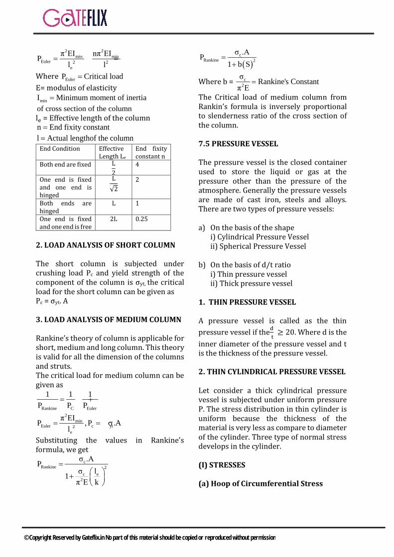
2 2min min
Eule 2r 2e
π EI nπ EIPl l
= =
Where EulerP Critical load= E= modulus of elasticity
minI Minimum moment of inertia= of cross section of the column le = Effective length of the column n End fixity constant= l Actual lengthof the column= End Condition Effective
Length Le
End fixity constant n
Both end are fixed L2 4
One end is fixed and one end is hinged
L√2
2
Both ends are hinged
L 1
One end is fixed and one end is free
2L 0.25
2. LOAD ANALYSIS OF SHORT COLUMN The short column is subjected under crushing load Pc and yield strength of the component of the column is σyt, the critical load for the short column can be given as Pc = σyt. A 3. LOAD ANALYSIS OF MEDIUM COLUMN Rankine’s theory of column is applicable for short, medium and long column. This theory is valid for all the dimension of the columns and struts. The critical load for medium column can be given as
Rankine C Euler
1 1 1P P P
= +
2min
Eulere
c yt2 P EIP , Al
.π= = σ
Substituting the values in Rankine’s formula, we get
cRankine 2
c e2
σ .APσ l1π E k
= +
( )c
Rankine 2σ .AP
1 b S=
+
Where b = c2
σ Rankine's Constantπ E
=
The Critical load of medium column from Rankin’s formula is inversely proportional to slenderness ratio of the cross section of the column. 7.5 PRESSURE VESSEL The pressure vessel is the closed container used to store the liquid or gas at the pressure other than the pressure of the atmosphere. Generally the pressure vessels are made of cast iron, steels and alloys. There are two types of pressure vessels: a) On the basis of the shape
i) Cylindrical Pressure Vessel ii) Spherical Pressure Vessel
b) On the basis of d/t ratio i) Thin pressure vessel ii) Thick pressure vessel
1. THIN PRESSURE VESSEL A pressure vessel is called as the thin pressure vessel if thed
t ≥ 20. Where d is the
inner diameter of the pressure vessel and t is the thickness of the pressure vessel. 2. THIN CYLINDRICAL PRESSURE VESSEL Let consider a thick cylindrical pressure vessel is subjected under uniform pressure P. The stress distribution in thin cylinder is uniform because the thickness of the material is very less as compare to diameter of the cylinder. Three type of normal stress develops in the cylinder. (I) STRESSES (a) Hoop of Circumferential Stress
© Copyright Reserved by Gateflix.in No part of this material should be copied or reproduced without permission
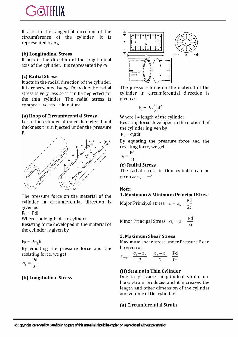
It acts in the tangential direction of the circumference of the cylinder. It is represented by σh.
(b) Longitudinal Stress It acts in the direction of the longitudinal axis of the cylinder. It is represented by σl. (c) Radial Stress It acts in the radial direction of the cylinder. It is represented by σr. The value the radial stress is very less so it can be neglected for the thin cylinder. The radial stress is compressive stress in nature. (a) Hoop of Circumferential Stress Let a thin cylinder of inner diameter d and thickness t is subjected under the pressure P.
The pressure force on the material of the cylinder in circumferential direction is given as FL = Pdl Where, l = length of the cylinder Resisting force developed in the material of the cylinder is given by
FR = h2σ lt By equating the pressure force and the resisting force, we get
hPdσ2t
=
(b) Longitudinal Stress
The pressure force on the material of the cylinder in circumferential direction is given as
2L d PF π
4×=
Where l = length of the cylinder Resisting force developed in the material of the cylinder is given by
lRF σ πdt= By equating the pressure force and the resisting force, we get
lPdσ4t
=
(c) Radial Stress The radial stress in thin cylinder can be given as rσ P= − Note: 1. Maximum & Minimum Principal Stress
Major Principal stress 1 hPdσ σ2t
= =
Minor Principal Stress 2 lPdσ σ4t
= =
2. Maximum Shear Stress Maximum shear stress under Pressure P can be given as
1 2 h lmax
σ σ σ σ Pdτ2 2 8t− −
= = =
(II) Strains in Thin Cylinder Due to pressure, longitudinal strain and hoop strain produces and it increases the length and other dimension of the cylinder and volume of the cylinder. (a) Circumferential Strain
© Copyright Reserved by Gateflix.in No part of this material should be copied or reproduced without permission

( )h lh
σ μσδd Pdε 2 μd E 4tE
−= = = −
(b) Longitudinal Strain
( )l hl
σ μσδl Pdε 1 2μl E 4tE
−= = = −
(c) Volumetric Strain
( )
v
v v c
v
δV δl δdε 2V l d
ε ε εPdε 5 4μ4tE
2
= = +
=
= −
+
3. THIN SPHERICAL PRESSURE VESSEL
a) Hoop of Circumferential Stress Let a thin sphere of inner diameter d and thickness t is subjected under the pressure P.
The pressure force on the material of the sphere in circumferential direction is given as
2L d PF π
4×=
Resisting force developed in the material of the Sphere is given by
hRF σ πdt= By equating the pressure force and the resisting force, we get
hPdσ4t
=
b) Longitudinal Stress The pressure force on the material of the sphere in circumferential direction is given
as 2L d PF π
4×=
Where l = length of the cylinder Resisting force developed in the material of the sphere is given by
lRF σ πdt= By equating the pressure force and the resisting force, we get
lPdσ4t
=
c) Radial Stress The radial stress in thin sphere can be given as
rσ P= − Maximum & Minimum Principal Stress
Major Principal stress 1,2 hPdσ σ4t
= =
Maximum Shear Stress Maximum shear stress under Pressure P can be given as
1 2 h lmax
σ σ σ στ 02 2− −
= = =
Strain in Thin Sphere Due to pressure, longitudinal strain and hoop strain produces and it increases the length and other dimension of the cylinder and volume of the cylinder. Circumferential Strain
( )h lh
σ μσδd Pdε 1 μd E 4tE
−= = = −
Volumetric Strain
( )hδV δd 3Pdε 3 1 μV d 4tE
= = = −
4. THICK PRESSURE VESSEL
© Copyright Reserved by Gateflix.in No part of this material should be copied or reproduced without permission

A pressure vessel is called as the thick
pressure vessel if the d 20t< . Where d is the
inner diameter of the pressure vessel and t is the thickness of the pressure vessel.Examples of thick pressure vessel are gun barrels, container under high pressure.
© Copyright Reserved by Gateflix.in No part of this material should be copied or reproduced without permission

Q.1 A pin-ended column of length L, modulus of elasticity E and second moment of the cross-sectional area I is loaded eccentrically by a compressive load P. The critical buckling load (Pcr) is given by
a) cr 2 2
EIPπ L
= b) 2
cr 2
π EIP3L
=
c) cr 2
πEIPL
= d) 2
cr 2
π EIPL
=
[GATE-2006]
Q.2 The rod PQ of length L and with flexural rigidity EI is hinged at both ends. For what minimum force F is it expected to buckle?
a) 2
2
π E IL
b) 2
2
2π E IL
c) 2
2
π E I2L
d) 2
2
π E I2L
[GATE-2008]
Q.3 A column has a rectangular cross-section of 10×20 mm and a length of 1m. The slenderness ratio of the column is close to a) 200 b) 346c) 477 d) 1000
[GATE-2011]
Q.4 For a long slender column of uniform cross section, the ratio of critical buckling load for the case with both ends clamped to the case with both the ends hinged is
a) 1 b) 2c) 4 d) 8
[GATE-2012]
Q.5 Consider a steel (Young’s modulus E = 200 GPa) column hinged on both sides. Its height is 1.0 m and cross –section is 10mm×20mm. The lowest Euler critical buckling load (in N) is _____.
[GATE-2015] Q.6 An initially stress-free massless
elastic beam of length L and circular cross-section with diameter d (d << L) is held fixed between two walls asshown. The beam material has Young’s modulus E and coefficient of thermal expansion α .
If the beam is slowly and uniformly heated, the temperature rise required to cause the beam to buckle is proportional to
[GATE 2017 (1)]
(A) d (B) d2
(C) d3 (D) d4
Q.7 A steel column of rectangular section (15 mm × 10 mm) and length 1.5 m is simply supported at both ends. Assuming modulus of elasticity, E = 200 GPa for steel, the critical axial load (in kN) is ____ (correct to two decimal places).
[GATE-2018(1)]
GATE QUESTIONS
© Copyright Reserved by Gateflix.in No part of this material should be copied or reproduced without permission
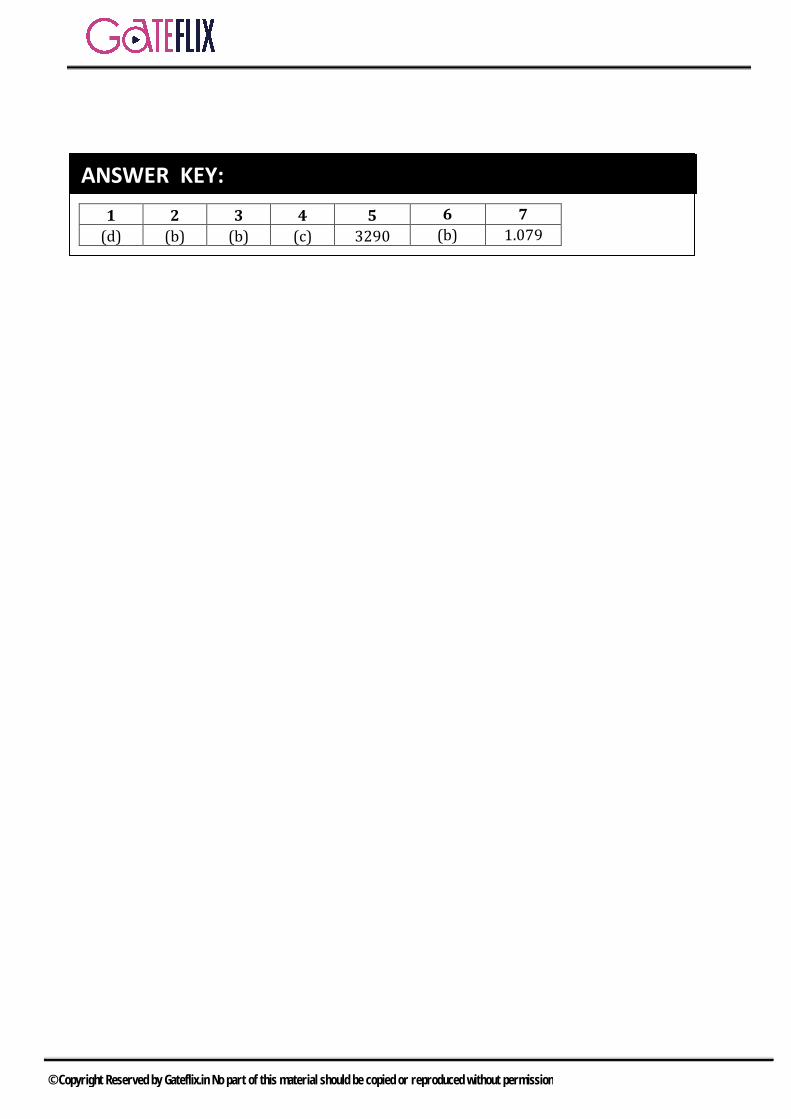
1 2 3 4 5 6 7 (d) (b) (b) (c) 3290 (b) 1.079
ANSWER KEY:
© Copyright Reserved by Gateflix.in No part of this material should be copied or reproduced without permission

Q.1 (d)
According to Euler’s theory, the crippling or buckling load (Pcr) under various end conditions is represented by a general equation,
2min
cr 2e
π EIPL
=
Where E = Modulus of elasticity I=Minimum mass-moment of inertia
eL = Effective length of column For both end pinned eL = L
2min
cr 2
π EIP gL
∴ =
Q.2 (b) For both ends hinged,
2
2
π EIPL
=
F cos 2
24 πL
5 EI° = (∵ F cos 45°=P)
2
2
F π EIL2
⇒ =
2
2
2π EIFL
∴ =
Q.3 (b) Given : l =1 meter, b = 20 mm, h = 10 mm
We know that, Slenderness ratio lk
=
Where minIkA
=
Where, Substitute the value, we get
3k 2.88 10−= ×
Slenderness ration = 3
12.88 10−×
=
347.22
Q.4 (c) According to Euler’s theory, the crippling or buckling load Euler(P ) under various end conditions is given by,
2min
Euler 2e
π EIPL
=
For (i). Both ends fixed eLL2
=
(ii).Both ends hinged e L L=∴ Ratio is 4
Q.5 (3285 to 3295)
Q.6 (b) Fth = Reaction offered by support or Buckling load.
2
2
EITE A 4l
πα∆ =
2 4
22
E D64TE D 4
4 l
ππ ×π
α∆ =
2DT∆ ∝
Q.7
EXPLANATIONS
© Copyright Reserved by Gateflix.in No part of this material should be copied or reproduced without permission
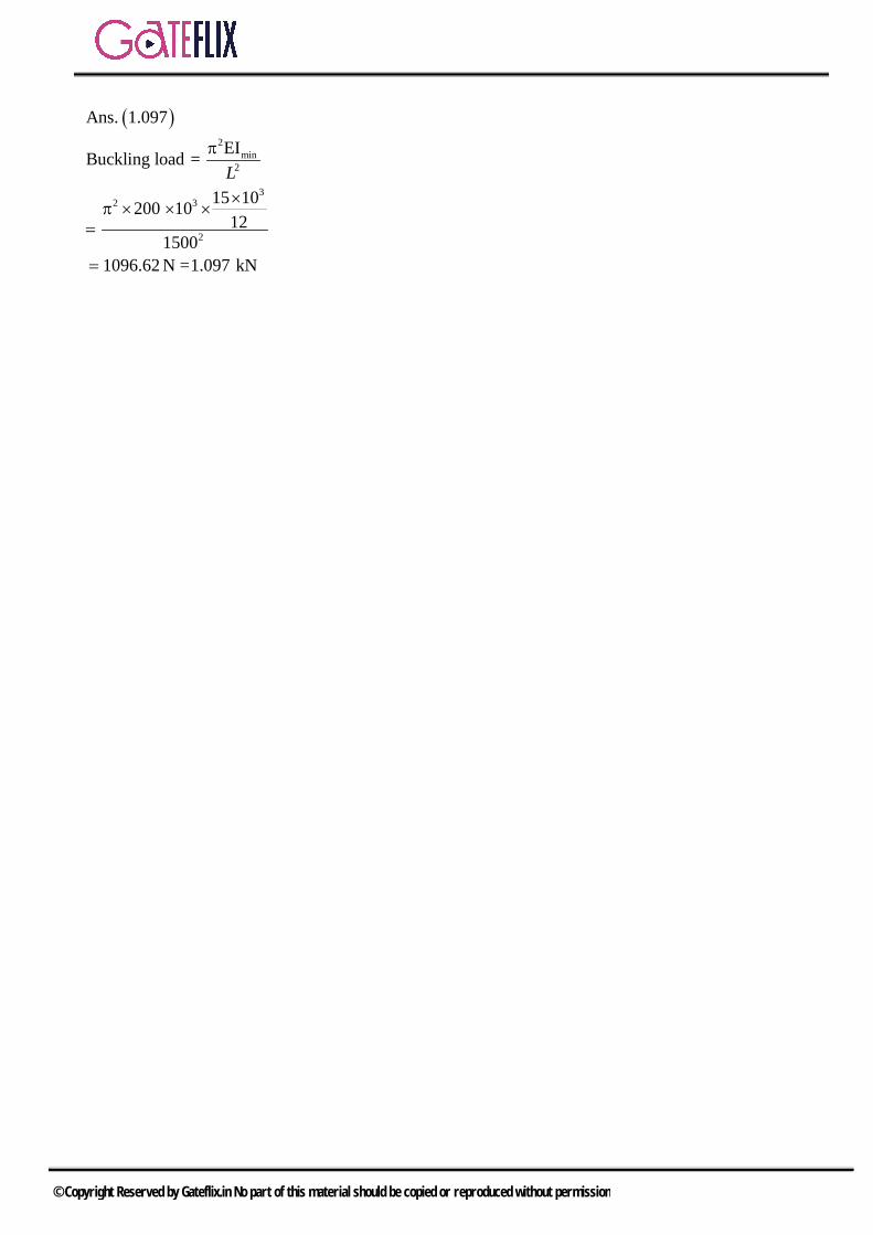
( )2
min2
32 3
2
Ans. 1.097
EIBuckling load =
15 10200 1012
15001096.62 N =1.097 kN
Lπ
π=
=
© Copyright Reserved by Gateflix.in No part of this material should be copied or reproduced without permission

Q.1 A thin cylinder of inner radius 500 mm and thickness 10 mm is subjected to an internal pressure of 5 MPa. The average circumferential (hoop) stress in MPa is a) 100 b) 250c) 500 d) 1000
[GATE-2011]
Q.2 A thin walled spherical shell is subjected to an internal pressure. If the radius of the shell is increased by 1% and the thickness is reduced by 1%, with the internal pressure remaining the same, the percentage change in the circumferential (hoop) stress is a) 0 b) 1c) 1.08 d) 2.02
[GATE-2012]
Q.3 A long thin walled cylindrical shell, closed at both the ends, is subjected to an internal pressure. The ratio of the hoop stress (circumferential stress) to longitudinal stress developed in the shell is a) 0.5 b) 1.0c) 2.0 d) 4.0
[GATE-2013]
Q.4 A thin gas cylinder with an internal radius of 100 mm is subject to an internal pressure of 10 MPa. The maximum permissible working stress is restricted to 100 MPa. The minimum cylinder wall thickness (in mm) for safe design must be___
[GATE-2014 (4)]
Q.5 A cylindrical tank with closed ends is filled with compressed air at a pressure of 500 kPa. The inner
radius of the tank is 2 m, and it has wall thickness of 10 mm. The magnitude of maximum in-plane shear stress (in MPa) is ____
[GATE-2015 (3)]
Q.6 A thin cylindrical pressure vessel with closed-ends is subjected to internal pressure. The ratio of circumferential (hoop) stress to the longitudinal stress is a) 0.25 b) 0.50c) 1.0 d) 2.0
[GATE-2016 (2)]
Q.7 A thin-walled cylindrical can with rigid end caps has a mean radius 100R mm and a wall thickness of 5 t mm. The can is pressurized and an additional tensile stress of50 MPa is imposed along the axial direction as shown in the figure. Assume that the state of stress in the wall is uniform along its length. If the magnitudes of axial and circumferential components of stress in the can are equal, the pressure (in MPa) inside the can is ___________ (correct to two decimal places).
[GATE 2018 (2)]
[GATE-2018 (2)]
GATE QUESTIONS
© Copyright Reserved by Gateflix.in No part of this material should be copied or reproduced without permission

1 2 3 4 5 6 7 (b) (d) 10 (c) 25 (d) 5
ANSWER KEY:
© Copyright Reserved by Gateflix.in No part of this material should be copied or reproduced without permission

Q.1 (b) Given : r = 500mm, t = 10 mm, P = 5MPa We know that average circumferential (hoop) stress is given by,
cPr 5 500σ 250MPat 10= ==
×
Q.2 (d)
Hoop stress pd4t
=
p= internal pressure d=diameter of shell t=thickness of shell
Now '
'
pd'4t
σ =
d’=1.01d t’=0.99t
p 1.01d' 1.0202σ4 0.99t×
∴σ = =×
σ% ’ ch σ 1 0ange 0σ−
×=
(1.0202 1)σ 100 2.02%σ−
= × =
Q.3 (10)
( )workingpdσ2t
d 2r 200m== =
w
pd 10 200t2σ 2 100
×= =
×= 10 mm
Q.4 (c) Hoop streets of circumferential stress is
1Prσt
=
and longitudinal or axial stress is
2Prσ2t
=
Ratio 1
2
σ Pr 2t 2σ t pr
= = × =
Q.5 (25) Maximum in-plane shear stress
maxpd 500 4τ8t 8 10
25MPa×= =
×=
Q.6 (d) r
c
rl
Pσ t 2Pσ
2t
= =
Q.7 Sol:
n
L
n L
PRCircumferential stress,t
PRAxialstress, 50 MPa2
Now,PR PR 50MPat 2
PR 50MPa2t
50 2 5P = 5 MPa100
t
t
=
= +
=
= +
=
=
EXPLANATIONS
© Copyright Reserved by Gateflix.in No part of this material should be copied or reproduced without permission
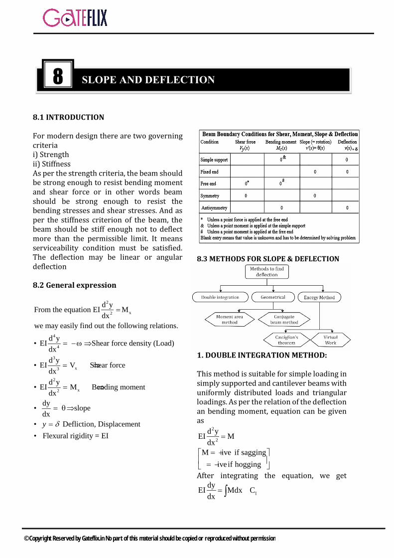
8.1 INTRODUCTION
For modern design there are two governing criteria i) Strengthii) StiffnessAs per the strength criteria, the beam should be strong enough to resist bending moment and shear force or in other words beam should be strong enough to resist the bending stresses and shear stresses. And as per the stiffness criterion of the beam, the beam should be stiff enough not to deflect more than the permissible limit. It means serviceability condition must be satisfied. The deflection may be linear or angular deflection
8.2 General expression
2
x2
4
4
3
x3
2
x2
d yFrom the equation EI Mdx
we may easily find out the following relations.d y• EI Shear force density (Load)dxd y• EI V Shear forcedxd y• EI M Bending momentdx
dy• slopedx
• Defliction, Dis
=
= −ω ⇒
= ⇒
= ⇒
= θ⇒
=y δ placement• Flexural rigidity = EI
8.3 METHODS FOR SLOPE & DEFLECTION
1. DOUBLE INTEGRATION METHOD:
This method is suitable for simple loading in simply supported and cantilever beams with uniformly distributed loads and triangular loadings. As per the relation of the deflection an bending moment, equation can be given as
2
2
d yEI Mdx
=
M ive if saggingiveif hogging
= + = − After integrating the equation, we get
1dyEI Mdx Cdx
= +∫
8 SLOPE AND DEFLECTION
© Copyright Reserved by Gateflix.in No part of this material should be copied or reproduced without permission

By applying the boundary condition we can find the value of C1.
1EIθ Mdx C= +∫ θ Slop of the beam at the given point.= Again integrating the equation of slope , we get
1 2EIy Mdx C x C= + +∫∫ y deflection of the beam at the given section= EI = Flexural Rigidity of the beam M = Bending moment at the given section 2. MACAULAY`S METHOD:
This is the convenient method for the beams subjected to point loadings or in general discontinuous loads or beams subjected to couples (concentrated moments). This method is similar to the double integration method but specialty of this method lies in the manner in which the bending moment at any section is expressed and in the manner in which integration is carried out. In Macaulay’s method a single equation is formed for all the loadings on a beam the equation is constructed in such a way that constants of the integration apply to all portions of the beam. 3. MOMENT AREA METHOD: (MOHR`S THEOREM)
This method is suitable for cantilevers and simply supported beams carrying symmetrical loadings and beams fixed at both ends i.e. those beams for which the area and Centre of gravity of area of B.M.D. can be found easily. It means this method is not suitable for triangular loading and irregular loading. This can also be used for non prismatic bars. This method can be used easily for i) Cantilever beams because slope at the
fixed end is zero) ii) Simply supported beams carrying
symmetrical loading because slope at mid span is zero.
iii) Beams fixed at both ends because the slope at each end is zero.
(a) Slop of beam As per Mohr’s theorem, total change in slope between B and A equals the area of B.M. diagram between B and A divided by the flexural rigidity EI.
B A1 (Area of B.M.D between A & B)EI
θ −θ =
In case of point A is not of zero slope and zero deflection, then the deflection of B with respect to the tangent at A equals the first moment about
(b) Deflection of beam As per Mohr’s theorem, total change in deflection between B and A equals the moment of area of B.M. diagram between B and A divided by the flexural rigidity EI.
B A1y y (Moment.of Area of EI
B.M.D between A & B)
− =
4. CONJUGATE BEAM METHOD: MOHR`S THEORIES This method is convenient if flexural rigidity of the beam is not uniform throughout the length of the beam. This method is suitable for beams carrying internal hinge. An Imaginary beam for which the load diagram
is MEI
diagram, of the given beam is called
the conjugate beam. If the slope of point A is
zero, B1 (Moment.of Area of B.M.DEI
between A & B about B)
δ =
If the slope of point A is not zero, then slope of point B is given as
B 1 2
A ab1.I (Moment.of Area of B.M.DEI
between A & B about B)
δ = δ + δ
= θ +
© Copyright Reserved by Gateflix.in No part of this material should be copied or reproduced without permission

5. STRAIN ENERGY METHOD: It is Suitable for cantilevers and beams having varying EI or varying depth of beam. This method is very useful in case of determinate frames and arches. This can also be used when internal hinge is provided. Let U is total strain energy of the structure
given by 2
xM dxU2EI
= ∫
In order to calculate the deflection under the point of application of the load P, the
deflection can be given as UyP
∂=∂
In order to calculate the slope under the point of application of the moment M, the
Slope can be given as UθM∂
=∂
6. CASTIGLIANO`S THEOREM
Let U is total strain energy of any structural member due to application of loads P1, P2, P3 at the points A1, A2,A3 and M1, M2, M3 at the points B1, B2,B3. Then differentiate of the strain energy with respect to any load gives the deflection at that point and with respect to Moment gives the slope at that point.
A1 A2 A31 2 3
U U Uy y yP P P
,∂ ∂ ∂= = =
∂ ∂ ∂
B1 B2 B31 2 3
U U Uθ θ θM M M
, ,∂ ∂ ∂= = =
∂ ∂ ∂
Points to be remembers: Treat all the load as a variables and carry
out partial differential To find the deflection or slope of a point
here there is no load or bending moment given assume a dummy load P or dummy moment respectively at that point and give a value zero at the end.
A,P 0
U yP
=
∂= ∂
and A,M 0
U θM
=
∂= ∂
8.4 SPECIAL CASE OF SLOPE AND DEFLECTION Case (A) Cantilever Beam 1) A cantilever of length l is subjected to
a couple M at its free end. Find the slope and deflection of the free end.
© Copyright Reserved by Gateflix.in No part of this material should be copied or reproduced without permission

Slope at the end B, BMlEI
θ =
Deflection at the free end 2Ml
2EIδ =
2) A cantilever of length `l` carrying point
load `W` at the free end
Slope at the free end,2
BWl2EI
θ =
Deflection of B, 3
bWl3EI
δ =
3) Cantilever of length `l` carrying a con-cent rated load W at a distance a from the fixed end.
Slope at B = slope at C2
B CW.a2EI
θ = θ =
Deflection at B, 3
bWa3EI
δ =
Deflection at C, 3 2
cWa Wa(l a)3EI 2EI
δ = + −
4) Cantilever of length `l` carrying a
uniformly distributed load w per unit length over the whole span
The slope at B, 3
Bwl6EI
θ =
The deflection at B, 4
Bwl6EI
δ =
5) Cantilever of length `l` carrying a udl
of w per unit run over a distance `a` from the fixed end.
The slope at B = the slope at C
3
B Cw.a6EI
θ = θ =
Deflection at B, 4
bw.a8EI
δ =
Deflection at C, EI
waalEIaw
C 6)(
8. 34
−+=δ
6) Cantilever carrying moment `Mo` at a distance a from fixed end
© Copyright Reserved by Gateflix.in No part of this material should be copied or reproduced without permission

Slope at free end, ob
M .aEI
θ =
Deflection at free end,
ob
M .a (2L a)2EI
δ = −
7) Cantilever of length ‘l’ carrying a
distributed load whose intensity varies uniformly from zero at the fixed end to w per unit run at the free end.
Slope at B, 3
bwl8EI
θ =
Deflection at the end EIwl
b
4
12011
=δ
Case (B) Simply supported beam 1) Simply supported beam of span l
carrying a point load W at mid span.
Slope at A = Slope at B 2
A Bwl
16EIθ = θ =
Deflection at the center of span C 3
CWl48EI
δ =
2) Simply supported beam AB of span `l` carrying a uniformly distributed load of w per unit length over the whole span.
Slope at the end A = slope at the end B
3
A Bwl
24EIθ = θ =
Maximum deflection at the center of
beam 4
c5 wl
384 EIδ =
3) A simply supported beam of span `l` carries a UDL for a distance
2`l from
left support A.
The deflection at the center is given by 4
C1 5 wl2 384 EI
δ = × ×
4) A beam of length `l` simply supported
at the ends carries a point load W at a distance `a` from the left end. Find the deflection under the load the maximum deflection.
© Copyright Reserved by Gateflix.in No part of this material should be copied or reproduced without permission

The deflection below the load (C) is
2 2
cWa b3EI l
δ =
The maximum deflection occurs at x
= 2 2l b
3− from left end, and is given by
2 3/2
maxW.b.(a 2ab)
9 3 EI l+
δ =
It has been found that maximum deflection always occurs within the
range of position l l2 13
±
5) A beam of length L is supported on two supports allowing equal over hangs. The distance between the support being `l`. The beam carries a point load W at its mid span.
The ratio between the l/L, if the down
ward defection at the center is equal to the upward deflection at the ends is
given by. 1 0.6L=
6) A been of length `l` with supports at the ends is subjected to a couple M at a distance a from the left end.
The slope at end A & B are
2 2A
M (2l 6al 3a )6EI l
θ = − +
2 2B
M (3a l )EI l
θ = −
The deflection at C below the moment applied is given by.
CM.a (1 a)(1 2a)
3EI l− −
δ =
7) Simply supported beam, carrying two concentrated loads at a distance `a` from each support.
Slope at each end a b
W.a(L a)2EI
−θ = θ =
Deflection at the center 2 2
c maxW.a(3L 4a )
24EI−
δ = δ =
8) A simply supported beam carries a
uniformly distributed load of varying intensity 0 to w from left end to right end B.
Slope at A =37 wl
360 EI
Slope at B = 3wl
45EI
Deflection at the center, 4
c5wl
768EIδ =
Maximum deflection
4
maxwl0.00652EI
δ =
© Copyright Reserved by Gateflix.in No part of this material should be copied or reproduced without permission
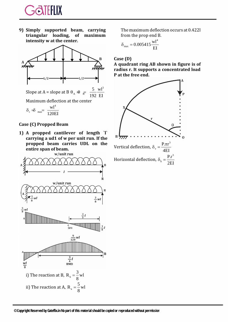
9) Simply supported beam, carrying triangular loading, of maximum intensity w at the center.
Slope at A = slope at B 3
A B5 wl
192 EIθ = θ =
Maximum deflection at the center
4
c maxwl
120EIδ = δ =
Case (C) Propped Beam
1) A propped cantilever of length `l` carrying a ud1 of w per unit run. If the propped beam carries UDL on the entire span of beam.
i) The reaction at B, b
3R wl8
=
ii) The reaction at A, a5R wl8
=
The maximum deflection occurs at 0.422l from the prop end B.
4
maxwl0.005415EI
δ =
Case (D) A quadrant ring AB shown in figure is of radius r. It supports a concentrated load P at the free end.
Vertical deflection, 3
vP. r4EIπ
δ =
Horizontal deflection, 3
hP.r2EI
δ =
© Copyright Reserved by Gateflix.in No part of this material should be copied or reproduced without permission

Q.1 A material has identical properties in all directions, it is said to be a) homogeneous b) isotropicc) elastic d) orthotropic
Q.2 The energy absorbed in a body, when it is strained within the elastic limits, is known as a) strain energyb) resiliencec) proof resilienced) modulus of resilience
Q.3 Toughness for mild steel under uniaxial tensile loading is given by the shaded portion of the stress-strain diagram as shown in
Q.4 Which of the following has no unit?
a) Kinematic viscosityb) Surface tensionc) Bulk modulusd) Strain
Q.5) Hooke's law holds good up to a) yield pointb) limit of proportionalityc) breaking pointd) elastic limit
Q.6) The linear relation between the stress and strain of a material is valid until a) fracture stressb) elastic limitc) ultimate stressd) proportional limit
Q.7) Match List-I (Materials) with List-II (Stress Strain curves) and select the correct Answer using the codes given below the lists:
List-I List-II A. Mild steel 1.
B. Pure copper 2.
C. Cast iron 3.
D. Pure aluminum 4.
ASSIGNMENT QUESTIONS
© Copyright Reserved by Gateflix.in No part of this material should be copied or reproduced without permission
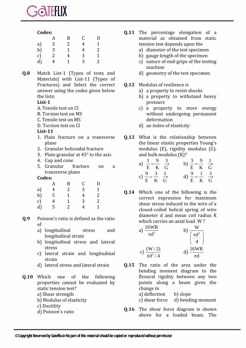
Codes: A B C D
a) 3 2 4 1 b) 3 1 4 2 c) 2 4 3 1 d) 4 1 3 2
Q.8 Match List-1 (Types of tests and
Materials) with List-11 (Types of Fractures) and Select the correct answer using the codes given below the lists: List-1 A. Tensile test on Cl B. Torsion test on MS C. Tensile test on MS D. Torsion test on Cl List-11 1. Plain fracture on a transverse
plane 2. Granular helicoidal fracture 3. Plain granular at 45° to the axis 4. Cup and cone 5. Granular fracture on a
transverse plane Codes:
A B C D a) 4 2 3 1 b) 5 1 4 2 c) 4 1 3 2 d) 5 2 4 1
Q.9 Poisson's ratio is defined as the ratio
of a) longitudinal stress and
longitudinal strain b) longitudinal stress and lateral
stress c) lateral strain and longitudinal
strain d) lateral stress and lateral strain
Q.10 Which one of the following properties cannot be evaluated by static tension test? a) Shear strength b) Modulus of elasticity c) Ductility d) Poisson's ratio
Q.11 The percentage elongation of a material as obtained from static tension test depends upon the a) diameter of the test specimen b) gauge length of the specimen c) nature of end-grips of the testing
machine d) geometry of the test specimen
Q.12 Modulus of resilience is
a) a property to resist shocks b) a property to withstand heavy
pressure c) a property to store energy
without undergoing permanent deformation
d) an index of elasticity Q.13 What is the relationship between
the linear elastic properties Young's modulus (E), rigidity modulus (G). and bulk modulus (K)?
a) 1 9 3E K G= + b) 3 9 1
E K G= +
c) 9 3 1E K G= + d) 9 1 3
E K G= +
Q.14 Which one of the following is the
correct expression for maximum shear stress induced in the wire of a closed-coiled helical spring of wire diameter d and mean coil radius R which carries an axial load W ?
a) 316WR
dπ b)
2
Wd4
π
c) 2(W / 2)
d / 4π d)
16WRdπ
Q.15 The ratio of the area under the bending moment diagram to the flexural rigidity between any two points along a beam gives the change in a) deflection b) slope c) shear force d) bending moment
Q.16 The shear force diagram is shown above for a loaded beam. The
© Copyright Reserved by Gateflix.in No part of this material should be copied or reproduced without permission

corresponding bending moment diagram is represented by
a)
b)
c)
d)
Q.17 A beam carrying a uniformly distributed load rests on two supports 'b' apart with equal overhangs 'a' at each end. The ratio b/a for zero bending moment at mid-span is
a) 12
b) 1
c) 23
d) 2
Q.18 For a simply supported beam of
length 'L', subjected to downward load of uniform intensity w, Match List-I with List-II and select the correct answer using the codes given below the lists : List-I A. Slope of shear force diagram B. Maximum shear force C. Maximum deflection D. Magnitude of maximum bending
moment List-II
1. 45wL
384EI
2. w
3. 4wL
8
4. wL2
Codes: A B C D
a) 1 2 3 4 b) 3 1 2 4 c) 3 2 1 4 d) 2 4 1 3
Q.19 The distribution of shear stress of a
beam is shown in the given figure.
The cross-section of the beam is a) I b) T b) d)
Q.20 Select the correct shear stress
distribution diagram for a square beam with a diagonal in a vertical position. a) b)
c) d)
Q.21 A structural member subjected to an
axial compressive force is called a) beam b) column c) frame d) strut
Q.22 Euler's formula holds good only for
a) short columns b) long columns c) both short and long column d) weak columns
© Copyright Reserved by Gateflix.in No part of this material should be copied or reproduced without permission

Q.23 What causes a short steel strut to fail? a) Fracture b) Shearing c) Buckling d) Yielding
Q.24 A column of rectangular section
(Ixx>Iyy) is subjected to an axial load. What is the axis about which the column will have a tendency to buckle? a) x-x axis b) y-y axis c) The diagonal of the section d) x-x or y-y axis without any preference
Q.25 Given that
PE = the crippling load given by Euler Pc = the load at failure due to direct compression PR = the load in accordance with the Rankine's criterion of failure Then PR is given by
a) E C(P P )2+
b) E CP P×
c) E E
C E
P PP P+
d)None of these
Q.26 Principal stresses on the outside
surface element of a thin cylindrical shell subjected to internal fluid pressure as shown in the figure, are represented by
a) b)
c) d)
Q.27 The stiffness of the beam shown in the figure below is ( 6 4105 mI 37 −= × ; L=0.5 m and E=200 GPa)
a) 812 10 N / m× b) 810 10 N / m× c) 84 10 N / m× d) 88 10 N / m×
Q.28) A mild steel specimen is tested in
tension up to fracture in a Universal Testing machine. Which of the following mechanical properties of the material can be evaluated from such a test? 1. Modulus of elasticity 2. Yield stress 3. Ductility 4. Tensile strength 5. Hardness 6. Modulus of rigidity Select the correct answer using the code given below: a) 1, 3, 5 and 6 b) 2, 3, 4 and 6 c) 1, 2, 5 and 6 d) 1, 2, 3 and 4
Q.29 A steel rod of length 300 mm is held between two fixed supports so that the rod cannot elongate or contract in the axial direction. If the temperature of the rod is raised by 20°C, the axial stress induced in the rod due to this rise in temperature is (Take E=200GPa, 6 01011.5 / C−α = × ) a) 46 MPa (Tension) b) 46 MPa (Compression) c) 23 MPa (Tension) d) 23 MPa (Compression)
Q.30 A steel cube of1m 1m 1m× × is subjected to hydrostatic pressure of 1 MPa. If for steel, Young's modulus is 200 GPa, and Poisson's ratio is 0.3, the approximate change in volume of the cube due to the hydrostatic pressure will be a) 6 36 10 m−− × b) 6 32 10 m−− × c) 3 31 10 m−− × d) 6 30.5 10 m−− ×
© Copyright Reserved by Gateflix.in No part of this material should be copied or reproduced without permission

Q.31 A bar of 20 mm diameter is tested in tension. It is observed that when a load of 30 kN is applied the extension measured over a gauge length of 200 mm is 0.12 mm and contraction in diameter is 0.0036 mm. The Poisson's ratio is a) 0.2 b) 0.3 c) 0.25 d) 0.33
Q.32 The bending moment for a loaded
beam is shown below:
The loading on the beam is represented by which one of the following diagram? a)
b)
c)
d)
Q.33
Shear force and bending moment diagrams for a beam ABCD are shown in figure. It can be concluded that
a) The beam has three supports b) End A is fixed c) A couple 2000 Nm acts at C d) A uniformly distributed load is
confined to portion BC only
Q.34 For a specific application Young's modulus of a material is 125 GPa and Poisson's ratio is 0.25, the modulus of rigidity is a) 50 GPa b) 60 GPa c) 80 GPa d) 90 GPa
Q.35 Match List-I (Property) with List-II
(Testing Machine) and select the correct answer using the codes given below the lists: List-I A. Tensile strength B. Impact strength C. Bending strength D. Fatigue strength List-II 1. Rotating bending machine 2. Three-point loading machine
3. Universal testing machine 4. lzod testing machine
Codes: A B C D a) 4 3 2 1 b) 3 2 1 4 c) 2 1 4 3 d) 3 4 2 1
Q.36 A uniform bar lying in the x-
direction is subjected to pure bending. Which one of the following tensors represents the strain variation when bending moment is about the z-axis (p, q and r constants)?
a) y
y
y
p 0 00 q 00 0 r
b) y
y
p 0 00 q 00 0 0
c)y
y
y
p 0 00 p 00 0 p
d)y
y
y
p 0 00 q 00 0 q
© Copyright Reserved by Gateflix.in No part of this material should be copied or reproduced without permission
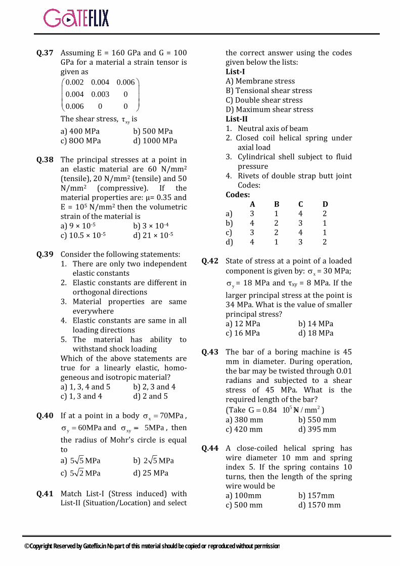
Q.37 Assuming E = 160 GPa and G = 100 GPa for a material a strain tensor is given as
0.002 0.004 0.0060.004 0.003 00.006 0 0
The shear stress, xyτ is a) 400 MPa b) 500 MPa c) 8OO MPa d) 1000 MPa
Q.38 The principal stresses at a point in an elastic material are 60 N/mm2
(tensile), 20 N/mm2 (tensile) and 50 N/mm2 (compressive). If the material properties are: μ= 0.35 and E = 105 N/mm2 then the volumetric strain of the material is a) 9 × 10⁻⁵ b) 3 × 10⁻⁴ c) 10.5 × 10⁻⁵ d) 21 × 10-5
Q.39 Consider the following statements:
1. There are only two independent elastic constants
2. Elastic constants are different in orthogonal directions
3. Material properties are same everywhere
4. Elastic constants are same in all loading directions
5. The material has ability to withstand shock loading
Which of the above statements are true for a linearly elastic, homo-geneous and isotropic material? a) 1, 3, 4 and 5 b) 2, 3 and 4
c) 1, 3 and 4 d) 2 and 5 Q.40 If at a point in a body x 70MPaσ = ,
y 60MPaσ = and xy 5MPaσ = − , then the radius of Mohr's circle is equal to a) 5 5 MPa b) 2 5 MPa c) 5 2 MPa d) 25 MPa
Q.41 Match List-I (Stress induced) with List-II (Situation/Location) and select
the correct answer using the codes given below the lists: List-I A) Membrane stress B) Tensional shear stress C) Double shear stress D) Maximum shear stress List-II 1. Neutral axis of beam 2. Closed coil helical spring under
axial load 3. Cylindrical shell subject to fluid
pressure 4. Rivets of double strap butt joint
Codes: Codes:
A B C D a) 3 1 4 2 b) 4 2 3 1 c) 3 2 4 1 d) 4 1 3 2
Q.42 State of stress at a point of a loaded
component is given by: xσ = 30 MPa; yσ = 18 MPa and τxy = 8 MPa. If the
larger principal stress at the point is 34 MPa. What is the value of smaller principal stress? a) 12 MPa b) 14 MPa
c) 16 MPa d) 18 MPa
Q.43 The bar of a boring machine is 45 mm in diameter. During operation, the bar may be twisted through O.01 radians and subjected to a shear stress of 45 MPa. What is the required length of the bar? (Take 5 2G 0.84 10 N / mm= × ) a) 380 mm b) 550 mm
c) 420 mm d) 395 mm Q.44 A close-coiled helical spring has
wire diameter 10 mm and spring index 5. If the spring contains 10 turns, then the length of the spring wire would be a) 100mm b) 157mm
c) 500 mm d) 1570 mm
© Copyright Reserved by Gateflix.in No part of this material should be copied or reproduced without permission
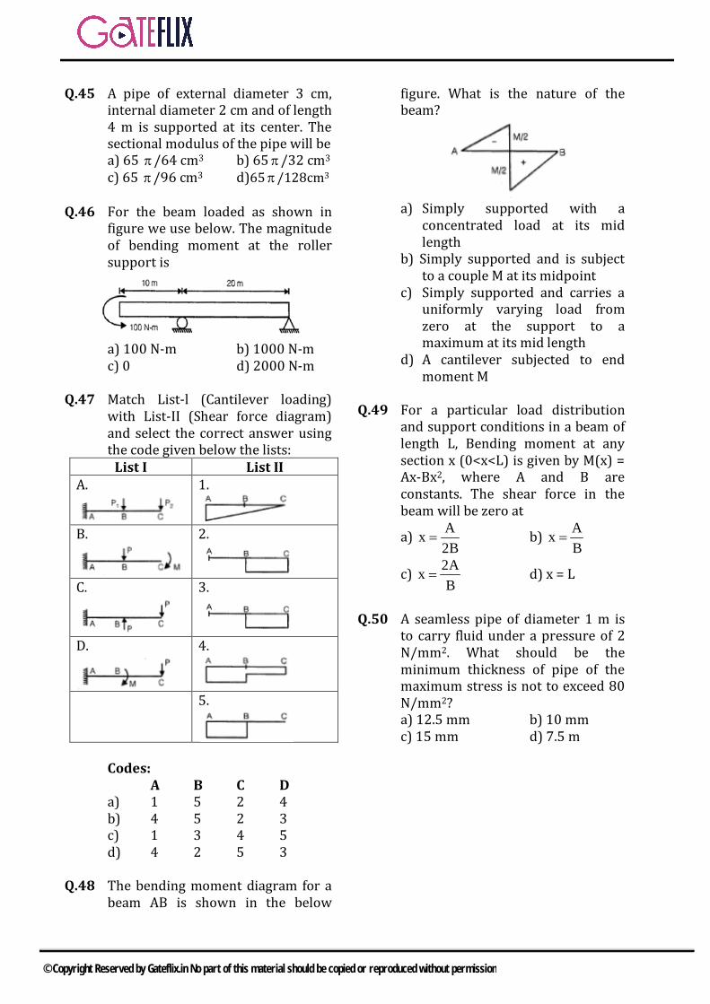
Q.45 A pipe of external diameter 3 cm, internal diameter 2 cm and of length 4 m is supported at its center. The sectional modulus of the pipe will be a) 65 π/64 cm3 b) 65 π/32 cm3 c) 65 π/96 cm3 d)65π/128cm3
Q.46 For the beam loaded as shown in
figure we use below. The magnitude of bending moment at the roller support is
a) 100 N-m b) 1000 N-m c) 0 d) 2000 N-m
Q.47 Match List-l (Cantilever loading)
with List-II (Shear force diagram) and select the correct answer using the code given below the lists:
List I List II A.
1.
B.
2.
C.
3.
D.
4.
5.
Codes: A B C D
a) 1 5 2 4 b) 4 5 2 3 c) 1 3 4 5 d) 4 2 5 3
Q.48 The bending moment diagram for a beam AB is shown in the below
figure. What is the nature of the beam?
a) Simply supported with a
concentrated load at its mid length
b) Simply supported and is subject to a couple M at its midpoint
c) Simply supported and carries a uniformly varying load from zero at the support to a maximum at its mid length
d) A cantilever subjected to end moment M
Q.49 For a particular load distribution
and support conditions in a beam of length L, Bending moment at any section x (0<x<L) is given by M(x) = Ax-Bx2, where A and B are constants. The shear force in the beam will be zero at
a) x A2B
= b) AxB
=
c) 2AxB
= d) x = L
Q.50 A seamless pipe of diameter 1 m is
to carry fluid under a pressure of 2 N/mm2. What should be the minimum thickness of pipe of the maximum stress is not to exceed 80 N/mm2? a) 12.5 mm b) 10 mm c) 15 mm d) 7.5 m
© Copyright Reserved by Gateflix.in No part of this material should be copied or reproduced without permission

Q.1 (b) Isotropy is the property in which material possess same properties in all directions.
Q.2 (b) Resilience can be defined as the ability of the material to absorb energy when deformed elastically and to release this energy when unloaded
Q.3 (d) Toughness is the ability of material to absorb the energy upto fracture point. i.e. toughness of material is the total area under stress-strain curve.
Q.4 (d)
Q.5 (b) Hooke’s law is valid up to proportional limit.
Q.6 (d) According to Hooke’s law stress is directly proportional to strain up to proportional limit.
Q.7 (a)
Q.8 (b) In Tensile test of ductile materials like mild steel, cup and cone failure occurs and failure plane is at 45° from the longitudinal axis. Where as in tensile test of brittle materials like cast iron, granular fracture occurs and failure plane is at 90° with longitudinal axis.
In Torsion test of brittle material, granular helicoidal fracture takes place and fracture plane is 45° from the longitudinal axis while in case of ductile material, plane fracture on a transverse plane takes place.
Q.9 (c) Poisson’s ratio is the ratio of lateral strain to the longitudinal strain.
1 2 3 4 5 6 7 8 9 10 11 12 13 14 (b) (b) (d) (d) (b) (d) (a) (b) (c) (a) (b) (c) (d) (a) 15 16 17 18 19 20 21 22 23 24 25 26 27 28 (b) (a) (d) (d) (b) (d) (d) (b) (a) (b) (c) (d) (c) (d) 29 30 31 32 33 34 35 36 37 38 39 40 41 42 (b) (a) (b) (d) (c) (a) (d) (d) (c) (a) (a) (c) (c) (b) 43 44 45 46 47 48 49 50 (c) (d) (c) (a) (b) (b) (a) (a)
ANSWER KEY:
EXPLANATIONS
© Copyright Reserved by Gateflix.in No part of this material should be copied or reproduced without permission
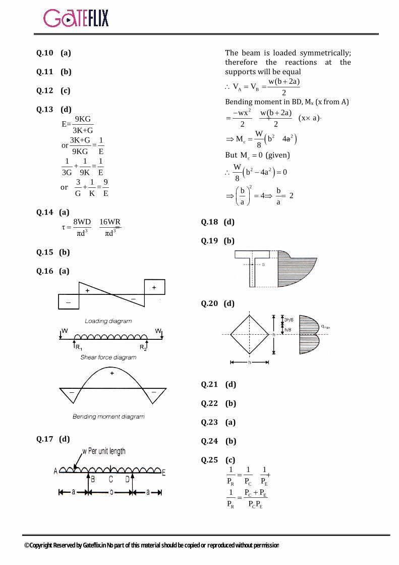
Q.10 (a) Q.11 (b) Q.12 (c) Q.13 (d)
9KGE=3K+G
3K+G 1or =9KG E
1 1 1+ =3G 9K E
or 3 1 9+ =G K E
Q.14 (a)
3 3
8WD 16WRτπd πd
= =
Q.15 (b) Q.16 (a)
Q.17 (d)
The beam is loaded symmetrically; therefore the reactions at the supports will be equal
A Bw(b 2a)V V
2+
∴ = =
Bending moment in BD, Mx (x from A)
2wx w(b 2a) (x a)
2 2− +
= + × −
( )2 2c
WM b 4a8
⇒ = −
But cM 0= (given)
( )2 2W b 4a 08
∴ − =
2b b4 2
a a ⇒ = ⇒ =
Q.18 (d) Q.19 (b)
Q.20 (d)
Q.21 (d) Q.22 (b) Q.23 (a) Q.24 (b) Q.25 (c)
R C E
1 1 1P P P
= +
C E
R C E
P P1P P P
+=
© Copyright Reserved by Gateflix.in No part of this material should be copied or reproduced without permission
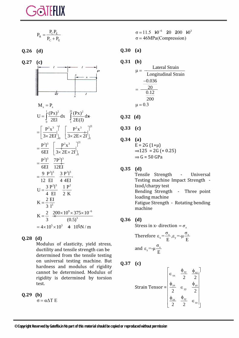
C ER
C E
P PPP P
=+
Q.26 (d) Q.27 (c)
x xM P=
1
l 2l2 2
0
(Px) (Px)U dx dx2El 2E(I)
= +∫ ∫
l 2l2 3 2 3
0 l
P x P x3 2EI 3 2E 2I
= + × × ×
2l2 3 2 3
l
P l P x6EI 3 2E 2I
= + × ×
2 3 2 3P l 7P l
6EI 12EI= +
2 3 2 39 P l 3 P l
12 EI 4 4EI= =
2 3 23 P l 1 PU
4 EI 2 K= =
3
2 EIK3 l
=
9 6
3
2 200 10 375 10K3 (0.5)
−× × ×= ×
5 3 84 10 10 4 10 N / m= = ×× × Q.28 (d)
Modulus of elasticity, yield stress, ductility and tensile strength can be determined from the tensile testing on universal testing machine. But hardness and modulus of rigidity cannot be determined. Modulus of rigidity is determined by torsion test.
Q.29 (b) σ αΔT E=
6 3σ 11.5 10 20 200 10−= × × × × σ 46MPa(Compression)= Q.30 (a) Q.31 (b)
Lateral StrainμLongitudinal Strain
= −
0.03620
0.12200
−
= −
μ 0.3=
Q.32 (d) Q.33 (c) Q.34 (a) E = 2G (1+μ) 125 = 2G (+ 0.25) G = 50 GPa Q.35 (d)
Tensile Strength - Universal Testing machine Impact Strength - Izod/charpy test Bending Strength - Three point loading machine
Fatigue Strength - Rotating bending machine
Q.36 (d)
Stress in x- direction = xσ
Therefore x xx y
σ σε = ,ε =-μE E
and xz
σε =-μE
Q.37 (c)
Strain Tensor =
xy xzxx
yx yzyy
zyzxzz
2 2
2 2
2 2
φ φ∈ φ φ
∈
φφ ∈
© Copyright Reserved by Gateflix.in No part of this material should be copied or reproduced without permission
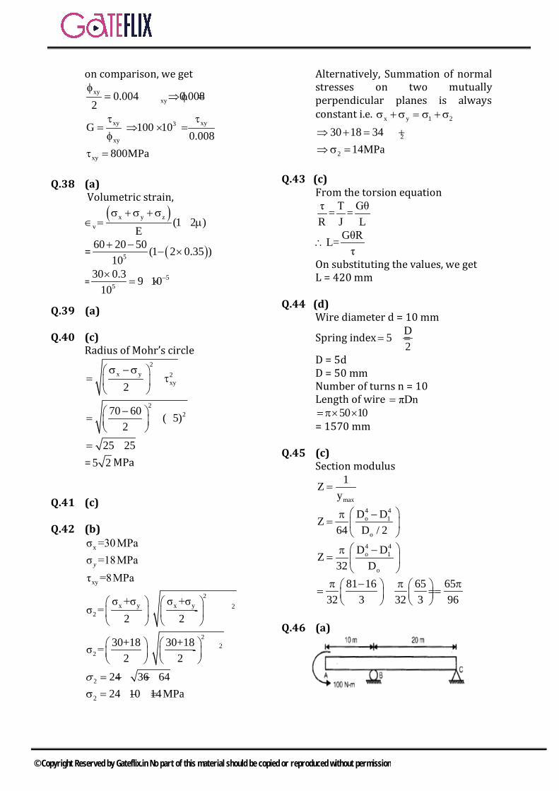
on comparison, we get
xyxy0.004 0.008
2φ
= ⇒ φ =
xy xy3
xy
G 100 100.008
τ τ= ⇒ × =φ
xy 800MPaτ = Q.38 (a) Volumetric strain,
( )x y z
v (1 2 )E
σ +σ +σ∈ = − µ
= ( )5 (160 20 5 01
. )0
2 0 35+− ×
−
= 55
30 0.3 9 1010
−×= ×
Q.39 (a) Q.40 (c)
Radius of Mohr’s circle 2
x y 2xy2
σ −σ = + τ
2270 60 ( 5)
2− = + −
25 25= + = 5 2 MPa
Q.41 (c) Q.42 (b) xσ =30MPa σ =18MPay
xyτ =8MPa 2
x y x y 22
σ +σ σ +σσ = - +τxy
2 2
22
230+18 30+18σ = - +8
2 2
2 24 36 64= − +σ
2 24 10 14MPaσ = − =
Alternatively, Summation of normal stresses on two mutually perpendicular planes is always constant i.e. x y 1 2σ +σ = σ +σ
230 18 34⇒ + = +σ 2 14MPa⇒σ = Q.43 (c)
From the torsion equation
τ T Gθ= =R J L
GθRL=τ
∴
On substituting the values, we get L = 420 mm Q.44 (d)
Wire diameter d = 10 mm
Spring index D52
= =
D = 5d D = 50 mm Number of turns n = 10 Length of wire πDn= 50 1 0=π× × = 1570 mm Q.45 (c)
Section modulus
max
1Zy
=
4 4o 1
o
D DZ64 D / 2
−π=
4 4o 1
o
D DZ32 D
−π=
81 16 65 6532 3 32 3 96π − π π = = =
Q.46 (a)
© Copyright Reserved by Gateflix.in No part of this material should be copied or reproduced without permission

Bending, moment at roller support = Moment about B in Beam portion AB
= 100 N-m Q.47 (b) Q.48 (d) Q.49 (a)
Given M(x) = Ax- Bx2
Shear force dM A 2Bxdx
= = −
For Shear force to be zero, A 2Bx 0 A 2Bx⇒ − = ⇒ =
Ax2B
∴ =
Q.50 (a) d = 1 m = 1000 m m= 2 N/mm2
Hoop stress npd2t
σ =
2 100080 12.5mm80×
= =
© Copyright Reserved by Gateflix.in No part of this material should be copied or reproduced without permission
CIVIL GATE QUESTIONS
© Copyright Reserved by Gateflix.in No part of this material should be copied or reproduced without permission

GATE SOLVED PAPER - CESTRENGTH OF MATERIALS
YEAR 2013 ONE MARK
Q. 1 Creep strain is(A) caused due to dead load only (B) caused due to live load only
(C) caused due to cyclic load only (D) independent of load
Q. 2 The “Plane section remain plane” assumption in bending theory implies(A) strain profile is linear (B) stress profile is linear
(C) both profiles are linear (D) shear deformation is neglected
Q. 3 A symmetric I-section (with width of each flange mm50= , thickness of web mm10= ) of steel is subjected to a shear force of 100 kN. Find the magnitude of
the shear stress (in N/mm2) in the web at its junction with the top flange.
Q. 4 Two steel column P (length L and yield strength MPaf 250y = ) have the same cross-section and end condition the ratio of bucking load of column P to that of column Q is(A) 0.5 (B) 1.0
(C) 2.0 (D) 4.0
YEAR 2013 TWO MARKS
Q. 5 2D stress at a point is given by a matrix
xx
yx
xy
yy
st
ts> H MPa
10030
3020= > H
The maximum shear stress in MPa is(A) 50 (B) 75
(C) 100 (D) 110
YEAR 2012 ONE MARK
Q. 6 The Poisson’s ratio is defined as
(A) lateral stressaxial stress (B) axial strain
lateral strain
(C) axial stresslateral stress (D) laterial strain
axial strian
Q. 7 The following statement are related to bending of beamsI. The slope of the bending moment diagram is equal to the shear force.
II. The slope of the shear force diagram is equal to the load intensity.
III. The slope of the curvature is equal to the flexural rotation
IV. The second derivative of the deflection is equal to the curvature.
The only FALSE statements is
© Copyright Reserved by Gateflix.in No part of this material should be copied or reproduced without permission

GATE SOLVED PAPER - CE STRENGTH OF MATERIALS
(A) I (B) II
(C) III (D) IV
Q. 8 The ratio of the theoretical critical buckling load for a column with fixed ends to that of another column with the same dimensions and material, but with pinned ends, is equal to(A) 0.5 (B) 1.0
(C) 2.0 (D) 4.0
YEAR 2012 TWO MARKS
Q. 9 The simply supported beam is subjected to a uniformly distributed load of intensity w per unit length, on half of the span from one end. The length of the span and the flexural stiffness are denoted as l and El respectively. The deflection at mid-span of the beam is
(A) Elwl
61445 4
(B) Elwl
7685 4
(C) Elwl
3845 4
(D) Elwl
1925 4
Q. 10 This sketch shows a column with a pin at the base and rollers at the top. It is subjected to an axial force P and a moment M at mid-height. The reaction(s) at R is/are.
(A) a vertical force equal to P
(B) a vertical force equal to /P 2
(C) a vertical force equal to P and a horizontal force equal to /M h
(D) a vertical force equal to /P 2 and a horizontal force equal to /M h
Q. 11 A symmetric frame PQR consists of two inclined members PQ and QR connected at ‘Q ’ with a rigid joint and hinged at ‘P ’ and ‘R ’. The horizontal length PR is l . If a weight W is suspended at Q , the bending moment at Q is
© Copyright Reserved by Gateflix.in No part of this material should be copied or reproduced without permission

GATE SOLVED PAPER - CE STRENGTH OF MATERIALS
(A) Wl2 (B) Wl
4
(C) Wl8 (D) zero
YEAR 2011 ONE MARK
Q. 12 Consider a simply supported beam with a uniformly distributed load having a neutral axis (NA) as shown. For points P (on the neutral axis) and Q (at the bottom of the beam) the state of stress is best represented by which of the following pairs ?
(A) (B)
(C) (D)
YEAR 2011 TWO MARKS
Q. 13 For the cantilever bracket, PQRS , loaded as shown in the adjoining figure (PQ RS L= = , and, QR L2= ), which of the following statements is FALSE ?
(A) The portion RS has a constant twisting moment with a value of WL2 .
(B) The portion QR has a varying twisting moment with a maximum value of WL .
(C) The portion PQ has a varying bending moment with a maximum value of WL .
(D) The portion PQ has no twisting moment.
Statement for Linked Q. 14 and 15 :A rigid beam is hinged at one end and supported on linear elastic springs (both having a stiffness of ‘k ’) at point ‘1’ and ‘2’, and an inclined load acts at ‘2’, as shown.
© Copyright Reserved by Gateflix.in No part of this material should be copied or reproduced without permission

GATE SOLVED PAPER - CE STRENGTH OF MATERIALS
Q. 14 Which of the following options represents the deflections 1d and 2d at points ‘1’ and ‘2’ ?
(A) kP
52 2
1d = b l and kP
54 2
2d = b l (B) kP
52
1d = b l and kP
54
2d = b l
(C) k
P52
21d = c m and
kP
54
22d = c m (D) k
P52 2
1d = c m and kP
54 2
2d = c m
Q. 15 If the load P equals 100 kN, which of the following options represents forces R1 and R2 in the springs at point ‘1’ and ‘2’?(A) 20 kNR1 = and 40 kNR2 = (B) 50 kNR1 = and 50 kNR2 =(C) 30 kNR1 = and 60 kNR2 = (D) 40 kNR1 = and 80 kNR2 =
YEAR 2010 ONE MARK
Q. 16 Two people weighing W each are sitting on a park of length L floating on water at /L 4 from either end. Neglecting the wright of the plank, the bending moment at the centre of the plank is
(A) WL8 (B) WL
16(C) WL
32 (D) zero
Q. 17 The major and minor principal stresses at a point are 3 MPa and 3- MPa respectively. The maximum shear stress at the point is(A) zero (B) 3 MPa
(C) 6 MPa (D) 9 MPa
Q. 18 The number of independent elastic constants for a linear elastic isotropic and homogeneous material is(A) 4 (B) 3
(C) 2 (D)1
Q. 19 The effective length of a column of length L fixed against rotation and translation at one end is(A) 0.5 L (B) 0.7 L
(C) 1.414 L (D) 2 L
Q. 20 A solid circular shaft of diameter d and length L is fixed at one end and free at the other end. A torque T is applied at the free end. The shear modulus of the material is G . The angle of twist at the free end is
(A) d GTL164p
(B) d GTL324p
(C) d GTL644p
(D) d G
TL1284p
© Copyright Reserved by Gateflix.in No part of this material should be copied or reproduced without permission

GATE SOLVED PAPER - CE STRENGTH OF MATERIALS
YEAR 2010 TWO MARKS
Q. 21 For the simply supported beam of length L , subjected to a uniformly distributed moment M kN-m per unt length as shown in the figure, the bending moment (in kN-m) at the mid-span of beam is
(A) zero (B) M
(C) ML (D) /M L
Q. 22 A disc of radius r has a hole of radius /r 2 cut-out as shown. The centroid of the remaining disc (shaded portion) at a radial distance from the centre “O” is
(A) /r 2 (B) /r 3
(C) /r 6 (D) /r 8
YEAR 2009 ONE MARK
Q. 23 A thin walled cylindrical pressure vessel having a radius of 0.5 m and wall thickness of 25 mm is subjected to an internal pressure of 700 kPa. The hoop stress developed is(A) 14 MPa (B) 1.4 MPa
(C) 0.14 MPa (D) 0.014 MPa
Q. 24 The point within the cross sectional plane of a beam through which the resultant of the external loading on the beam has to pass through to ensure pure bending without twisting of the cross-section of the beam is called(A) moment centre (B) centroid
(C) shear centre (D) elastic center
YEAR 2009 TWO MARKS
Q. 25 Consider the following statements :1. On a principal plane, only normal stress acts.
2. On a principal plane, both normal and shear stresses act.
3. On a principal plane, only shear stress acts
4. Isothermal state of stress is independent of frame of reference.
Which of the above statements is/are correct ?(A) 1 and 4 (B) 2 only
(C) 2 and 4 (D) 2 and 3
© Copyright Reserved by Gateflix.in No part of this material should be copied or reproduced without permission

GATE SOLVED PAPER - CE STRENGTH OF MATERIALS
Q. 26 A hollow circular shaft has an outer diameter of 100 mm and a wall thickness of 25 mm. The allowable shear stress in the shaft is 125 MPa. The maximum torque the shaft can transmit is(A) 46 kNm (B) 24.5 kNm
(C) 23 kNm (D) 11.5 kNm
Q. 27 Match List-I (Shear Force Diagrams) beams with List-II (Diagram of beams with supports and loading) and select the correct answer by using the codes given below the lists :
© Copyright Reserved by Gateflix.in No part of this material should be copied or reproduced without permission

GATE SOLVED PAPER - CE STRENGTH OF MATERIALS
Codes : a b c d(A) 3 1 2 4(B) 3 4 2 1(C) 2 1 4 3(D) 2 4 3 1
Statement for Linked Q. 28 & 29 :In the cantilever beam PQR shown in figure below, the segment PQ has flexural rigidity EI and the segment QR has infinite flexural rigidity
Q. 28 The deflection and slope of the beam at Q are respectively
(A) 65
23
EIWL and EI
WL3 2
(B) 3 EI 2WL and EI
WL3 2
(C) 2 EIWL and EI
WL3 2
(D) 3 EI 23WL and EI
WL3 2
Q. 29 The deflection of the beam at R is
(A) EI8 WL3
(B) 6 EI5 WL3
(C) 3 EI7 WL3
(D) 6 EI8 WL3
YEAR 2008 ONE MARK
Q. 30 A mild steel specimen is under uniaxial tensile stress. Young’s modulus and yield stress for mild steel are 2 105
# MPa and 250 MPa respectively. The maximum amount of strain energy per unit volume that can be stored in this specimen without permanent set is(A) 156 Nmm/mm3 (B) 15.6 Nmm/mm3
(C) 1.56 Nmm/mm3 (D) 0.156 Nmm/mm3
YEAR 2008 TWO MARKS
Q. 31 Cross-section of a column consisting to two steel strips, each of thickness t and width b is shown in the figure below. The critical loads of the column with perfect bond and without bond between the strips are P and P0 respectively. The ratio
/P P0 is
© Copyright Reserved by Gateflix.in No part of this material should be copied or reproduced without permission
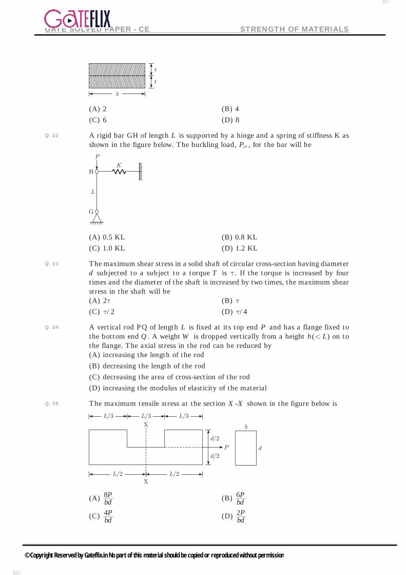
GATE SOLVED PAPER - CE STRENGTH OF MATERIALS
(A) 2 (B) 4
(C) 6 (D) 8
Q. 32 A rigid bar GH of length L is supported by a hinge and a spring of stiffness K as shown in the figure below. The buckling load, Pcr , for the bar will be
(A) 0.5 KL (B) 0.8 KL
(C) 1.0 KL (D) 1.2 KL
Q. 33 The maximum shear stress in a solid shaft of circular cross-section having diameter d subjected to a subject to a torque T is t. If the torque is increased by four times and the diameter of the shaft is increased by two times, the maximum shear stress in the shaft will be(A) 2t (B) t(C) /2t (D) /4t
Q. 34 A vertical rod PQ of length L is fixed at its top end P and has a flange fixed to the bottom end Q . A weight W is dropped vertically from a height ( )h L< on to the flange. The axial stress in the rod can be reduced by(A) increasing the length of the rod
(B) decreasing the length of the rod
(C) decreasing the area of cross-section of the rod
(D) increasing the modulus of elasticity of the material
Q. 35 The maximum tensile stress at the section X -X shown in the figure below is
(A) bdP8
(B) bdP6
(C) bdP4
(D) bdP2
© Copyright Reserved by Gateflix.in No part of this material should be copied or reproduced without permission
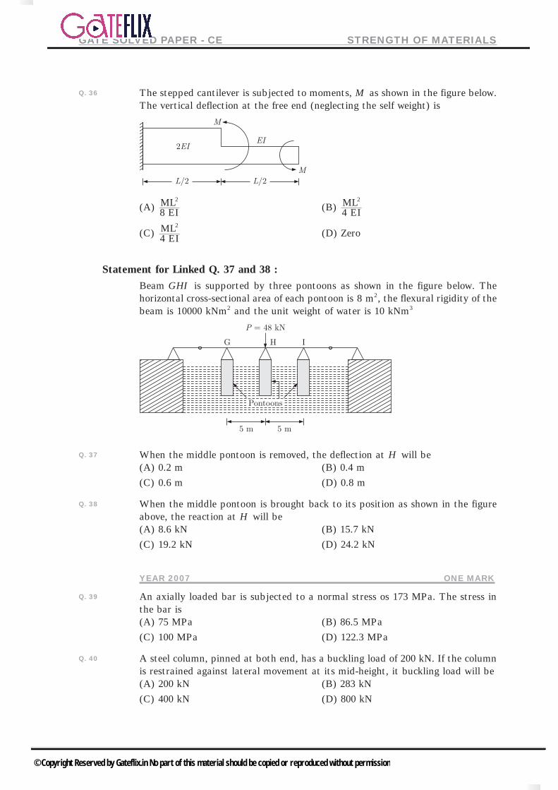
GATE SOLVED PAPER - CE STRENGTH OF MATERIALS
Q. 36 The stepped cantilever is subjected to moments, M as shown in the figure below. The vertical deflection at the free end (neglecting the self weight) is
(A) 8 EIML2
(B) 4 EIML2
(C) 4 EIML2
(D) Zero
Statement for Linked Q. 37 and 38 :Beam GHI is supported by three pontoons as shown in the figure below. The horizontal cross-sectional area of each pontoon is 8 m2, the flexural rigidity of the beam is 10000 kNm2 and the unit weight of water is 10 kNm3
Q. 37 When the middle pontoon is removed, the deflection at H will be(A) 0.2 m (B) 0.4 m
(C) 0.6 m (D) 0.8 m
Q. 38 When the middle pontoon is brought back to its position as shown in the figure above, the reaction at H will be(A) 8.6 kN (B) 15.7 kN
(C) 19.2 kN (D) 24.2 kN
YEAR 2007 ONE MARK
Q. 39 An axially loaded bar is subjected to a normal stress os 173 MPa. The stress in the bar is(A) 75 MPa (B) 86.5 MPa
(C) 100 MPa (D) 122.3 MPa
Q. 40 A steel column, pinned at both end, has a buckling load of 200 kN. If the column is restrained against lateral movement at its mid-height, it buckling load will be(A) 200 kN (B) 283 kN
(C) 400 kN (D) 800 kN
© Copyright Reserved by Gateflix.in No part of this material should be copied or reproduced without permission

GATE SOLVED PAPER - CE STRENGTH OF MATERIALS
Q. 41 For an isotropic material, the relationship between the Young’s modulus (E), shear modulus (G) and Poisson’s ratio (m) is given by
(A) ( )
G E2 1 m= + (B)
( )E E
2 1 m= +
(C) ( )
G E1 2m= + (D)
( )G E
2 1 2m= -
YEAR 2007 TWO MARKS
Q. 42 A metal bar of length 100 mm is inserted between two rigid supports and its temperature is increased by 10 Cc . If the coefficient of thermal expansion is 12 10 per C6
# c- and the Young’s modulus is 2 105# MPa, the stress in the bar
is(A) zero (B) 12 MPa
(C) 24 MPa (D) 2400 MPa
Q. 43 A rigid bar is suspended by three rods made of the same material as shown in the figure. The area and length of the central rod are 3 A and L , respectively while that of the two outer rods are A2 and L2 , respectively. If a downward force of 50 kN is applied to the rigid bar, the forces in the central and each of the outer rods will be(A) 16.67 kN each (B) 30 kN and 15 kN
(C) 30 kN and 10 kN (D) 21.4 kN and 14.3 kN
Q. 44 The maximum and minimum shear stresses in a hollow circular shaft of outer diameter 20 mm and thickness 2 mm, subjected to a torque of 92.7 Nm will be
(A) 59 MPa and 47.2 MPa (B) 100 MPa and 80 MPa
(C) 118 MPa and 160 MPa (D) 200 MPa and 160 MPa
Q. 45 The shear stress at the neutral axis in a beam of triangular section with a base of 40 mm and height 20 mm, subjected to a shear force of 3 kN is(A) 3 MPa (B) 6 MPa
(C) 10 MPa (D) 20 MPa
Q. 46 U1 and U2 are the strain energies stored in a prismatic bar due to axial tensile forces P1 and P2, respectively. The strain energy U stored in the same bar due to combined action of P1 and P2 will be(A) U U U1 2= + (B) U U U1 2=(C) U U U< 1 2+ (D) U U U> 1 2+
© Copyright Reserved by Gateflix.in No part of this material should be copied or reproduced without permission

GATE SOLVED PAPER - CE STRENGTH OF MATERIALS
YEAR 2006 ONE MARK
Q. 47 Mohr’s circle for the state of stress defined by 300
030> H MPa is a circle with
(A) centre at (0, 0) and radius 30 MPa (B) centre at (0, 0) and radius 60 MPa
(C) centre at (30, 0) and radius 30 MPa (D) centre at (30, 0) and zero radius
Q. 48 A long shaft of diameter d is subjected to twisting moment T at its ends. The maximum normal stress acting at its cross-section is equal to
(A) zero (B) dT163p
(C) dT323p (D
dT643p
Q. 49 The buckling load P Pcr= for the column AB in figure, as KT approaches infinity,
becomes LEI2
2
ap
Where a is equal to(A) 0.25 (B) 1.00
(C) 2.05 (D) 4.00
YEAR 2006 TWO MARKS
Q. 50 A thin-walled long cylindrical tank is inside radius r is subjected simultaneously to internal gas pressure p and axial compressive force F at its ends. In order to produce ‘pure shear’ state of stress in the wall of the cylinder, F should be equal to(A) p r2p (B) p r2 2p(C) p r3 2p (D) p r4 2p
Q. 51 Consider the beam AB shown in the figure below. Part AC of the beam is rigid while Part CB has the flexural rigidity EI . Identify the correct combination of deflection at end B and bending moment at end A, respectively
(A) ,EIPL PL3 2
3
(B) ,EIPL PL3
3
(C) ,2EIPL PL3
8 3
(D) ,EIPL PL3
8 3
© Copyright Reserved by Gateflix.in No part of this material should be copied or reproduced without permission

GATE SOLVED PAPER - CE STRENGTH OF MATERIALS
Q. 52 A simply supported beam AB has the bending moment diagram as shown in the following figure.
The beam is possibly under the action of following loads(A) Couples of M at C and 2M at D
(B) Couples of 2M at C and M at D
(C) Concentrated loads of M/L at C and 2M/L at D
(D) Concentrated load of M/L at C and couple of 2M at D
Q. 53 A beam with the cross-section given is subjected to a positive bending moment (causing compression at the top) of 16 kNm acting around the horizontal axis. The tensile force acting on the hatched area of the cross-section is
(A) zero (B) 5.9 kN
(C) 8.9 kN (D) 17.8 kN
Q. 54 If a beam of rectangular cross-section is subjected to a vertical shear force V , the shear force carried by the upper one-third of the cross-section is
(A) zero (B) V277
(C) V278
(D) V3
Q. 55 For the section shown below, second moment of the area about an axis /d 4 distance above the bottom of the area is
(A) bd48
3
(B) bd12
3
(C) bd48
7 3
(D) bd3
3
© Copyright Reserved by Gateflix.in No part of this material should be copied or reproduced without permission

GATE SOLVED PAPER - CE STRENGTH OF MATERIALS
Q. 56 I -section of a beam is formed by gluing wooden planks as shown in the figure below. If this beam transmits a constant vertical shear force of 3000 N, the glue at any of the four joint will be subjected to a shear force (in kN per meter length) of
(A) 3.0 (B) 4.0
(C) 8.0 (D) 10.7
Common Data For Q. 57 and 58 :Consider a propped cantilever beam ABC under two leads of magnitude P each as shown in the figure below. Flexural rigidity of the beam is EI .
Q. 57 The reaction at C is
(A) ( )LPa
169 upwards (B) ( )L
Pa169 downwards
(C) ( )LPa89 upwards (D) ( )L
Pa89 downwards
Q. 58 The rotation at B is
(A) ( )EIPLa
165 clockwise (B) ( )EI
PLa165 anticlockwise
(C) ( )EIPLa
1659 clockwise (D) ( )EI
PLa1659 anticlockwise
YEAR 2005 ONE MARK
Q. 59 The symmetry of stress tensor at a point in the body under equilibrium is obtained from(A) conserved of mass
(B) force equilibrium equations
(C) moment equilibrium equations
(D) conservation of energy
© Copyright Reserved by Gateflix.in No part of this material should be copied or reproduced without permission
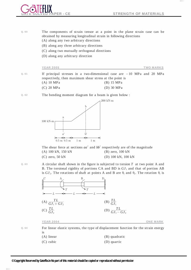
GATE SOLVED PAPER - CE STRENGTH OF MATERIALS
Q. 60 The components of strain tensor at a point in the plane strain case can be obtained by measuring longitudinal strain in following directions(A) along any two arbitrary directions
(B) along any three arbitrary directions
(C) along two mutually orthogonal directions
(D) along any arbitrary direction
YEAR 2005 TWO MARKS
Q. 61 If principal stresses in a two-dimensional case are 10- MPa and 20 MPa respectively, then maximum shear stress at the point is(A) 10 MPa (B) 15 MPa
(C) 20 MPa (D) 30 MPa
Q. 62 The bending moment diagram for a beam is given below :
The shear force at sections aal and bbl respectively are of the magnitude(A) 100 kN, 150 kN (B) zero, 100 kN
(C) zero, 50 kN (D) 100 kN, 100 kN
Q. 63 A circular shaft shown in the figure is subjected to torsion T at two point A and B. The torsional rigidity of portions CA and BD is GJ1 and that of portion AB is GJ2. The rotations of shaft at points A and B are 1q and 2q . The rotation 1q is
(A) GJ GJTL1 2+ (B) GJ
TL1
(C) GJTL
2 (D) GJ GJ
TL1 2-
YEAR 2004 ONE MARK
Q. 64 For linear elastic systems, the type of displacement function for the strain energy is(A) linear (B) quadratic
(C) cubic (D) quartic
© Copyright Reserved by Gateflix.in No part of this material should be copied or reproduced without permission

GATE SOLVED PAPER - CE STRENGTH OF MATERIALS
YEAR 2004 TWO MARKS
Q. 65 In a two dimensional stress analysis, the state of stress at a point is shown below. If 120 MPas = and 70 MPat = , andx ys s , are respectively,
(A) 26.7 MPa and 172.5 MPa (B) 54 MPa and 128 MPa
(C) 67.5 MPa and 213.3 MPa (D) 16 MPa and 138 MPa
Q. 66 For the linear elastic beam shown in the figure, the flexural rigidity, EI is 781250 kNm2. When 10w kN/m= , the vertical reaction RA at A is 50 kN. The value of RA for 100w kN/m= is
(A) 500 kN (B) 425 kN
(C) 250 kN (D) 75 kN
Q. 67 A homogeneous, simply supported prismatic beam of width B , depth D and span L is subjected to a concentrated load of magnitude P . The load can be placed anywhere along the span of the beam. The maximum flexural stress developed in beam is
(A) BDPL
32
2 (B) BDPL
43
2
(C) BDPL
34
2 (D) BDPL
23
2
Q. 68 A circular solid shaft of span 5L m= is fixed at one end and free at other end. A twisting moment 100T kNm= is applied at the free end. The torsional rigidity GH is 50000 kNm /rad2 .Following statements are made for this shaft :1. The maximum rotation is 0.01 rad
2. The torsional strain energy is 1 kNm
With reference to the above statements, which of the following applies ?(A) Both statements are true
(B) Statement 2 is true but 2 is false
(C) Statement 2 is true but 1 is false
(D) Both the statements are false
© Copyright Reserved by Gateflix.in No part of this material should be copied or reproduced without permission
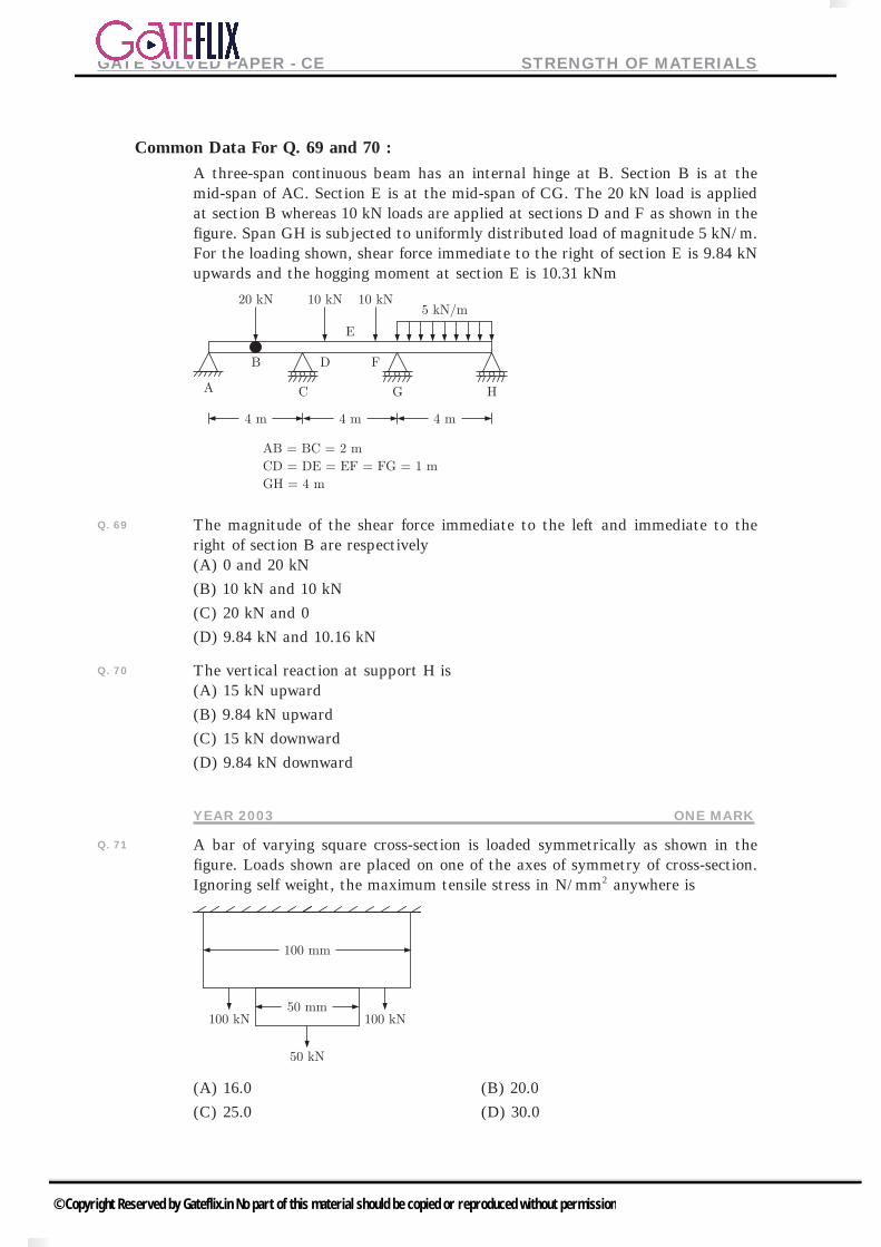
GATE SOLVED PAPER - CE STRENGTH OF MATERIALS
Common Data For Q. 69 and 70 :A three-span continuous beam has an internal hinge at B. Section B is at the mid-span of AC. Section E is at the mid-span of CG. The 20 kN load is applied at section B whereas 10 kN loads are applied at sections D and F as shown in the figure. Span GH is subjected to uniformly distributed load of magnitude 5 kN/m. For the loading shown, shear force immediate to the right of section E is 9.84 kN upwards and the hogging moment at section E is 10.31 kNm
Q. 69 The magnitude of the shear force immediate to the left and immediate to the right of section B are respectively(A) 0 and 20 kN
(B) 10 kN and 10 kN
(C) 20 kN and 0
(D) 9.84 kN and 10.16 kN
Q. 70 The vertical reaction at support H is(A) 15 kN upward
(B) 9.84 kN upward
(C) 15 kN downward
(D) 9.84 kN downward
YEAR 2003 ONE MARK
Q. 71 A bar of varying square cross-section is loaded symmetrically as shown in the figure. Loads shown are placed on one of the axes of symmetry of cross-section. Ignoring self weight, the maximum tensile stress in N/mm2 anywhere is
(A) 16.0 (B) 20.0
(C) 25.0 (D) 30.0
© Copyright Reserved by Gateflix.in No part of this material should be copied or reproduced without permission

GATE SOLVED PAPER - CE STRENGTH OF MATERIALS
Q. 72 A curved member with a straight vertical leg is carrying a vertical load at Z , as shown in the figure. The stress resultants in the XY segment are
(A) bending moment, shear force and axial force
(B) bending moment and axial force only
(C) bending moment and shear force only
(D) axial force only
YEAR 2003 TWO MARKS
Q. 73 The state of two dimensional stresses acting on a concrete lamina consists of a direct tensile stress, 1.5 N/mmx
2s = , and shear stress, 1.20 N/mm2t = , which cause cracking of concrete. Then the tensile strength of the concrete in N/mm2 is(A) 1.50
(B) 2.08
(C) 2.17
(D) 2.29
Q. 74 A " "H shaped frame of uniform flexural rigidity EI is located as shown in the figure. The relative outward displacement between points K and O is
(A) EIRLh2
(B) EIRL h2
(C) EIRLh3
2
(D) EIRL h3
2
© Copyright Reserved by Gateflix.in No part of this material should be copied or reproduced without permission

GATE SOLVED PAPER - CE STRENGTH OF MATERIALS
Q. 75 A simply supported beam of uniform rectangular cross-section of width b and depth h is subjected to linear temperature gradient 0c at the top and Tc at the bottom, as shown in the figure. The coefficient of linear expansion of the beam material is a . The resulting vertical deflection at the mid-span of the beam is
(A) LTh8 upward
2a
(B) hTL8 upward
2a
(C) LTh8 downward
2a
(D) hTL8 downward
2a
Q. 76 List I shows different loads acting on a beam and List II shows different bending moment distributions. Match the load with the corresponding bending moment diagram.
Codes : A B C D(A) 4 2 1 3(B) 5 4 1 3(C) 2 5 3 1(D) 2 4 1 3
© Copyright Reserved by Gateflix.in No part of this material should be copied or reproduced without permission

GATE SOLVED PAPER - CE STRENGTH OF MATERIALS
Q. 77 A long structural column (length L= ) with both ends hinged is acted upon by an axial compressive load, P . The differential equation governing the bending of column is given by :
EIdxd y
2
2
Py=-
Where y is the structural lateral deflection and EI is the flexural rigidity. The first critical load on column responsible for its buckling is given by
(A) LEI2
2p (B)
LEI2
2
2p
(C) LEI22
2p (D) L
EI42
2p
YEAR 2002 ONE MARK
Q. 78 The shear modulus Gh, modulus of elasticity E^ h and the Poisson’s ratio v^ h of a material are related as
(A) Gv
E2 1
=+^ h6 @
(B) Ev
G2 1
=+^ h6 @
(C) Gv
E2 1
=-^ h6 @
(D) GvE
2 1=
-^ h6 @
Q. 79 For the loading given in the figure below, two statements (I and II) are made
I. Memeber AB carries shear force and bending moment
II. Member BC carries axial load and shear force
Which of these statement is true?
(A) Statement I True but II is False (B) Statement I is False but II is True
(C) Both statement I and II are True (D) Both statement I and II are False
YEAR 2002 TWO MARKS
Q. 80 In the propped cantilever beam carrying a uniformly distributed load of /N mw , shown in the following figure, the reaction at the support B is
(A) wL85 (B) wL8
3
(C) wL21 (D) wL4
3
© Copyright Reserved by Gateflix.in No part of this material should be copied or reproduced without permission
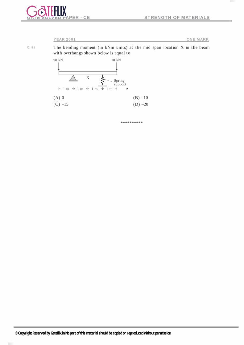
GATE SOLVED PAPER - CE STRENGTH OF MATERIALS
YEAR 2001 ONE MARK
Q. 81 The bending moment (in kNm units) at the mid span location X in the beam with overhangs shown below is equal to
z
(A) 0 (B) –10
(C) –15 (D) –20
**********
© Copyright Reserved by Gateflix.in No part of this material should be copied or reproduced without permission

GATE SOLVED PAPER - CE STRENGTH OF MATERIALS
ANSWER KEY
STRENGTH OF MATERIALS
1 2 3 4 5 6 7 8 9 10
(A) (A) 71.12 (D) (A) (B) (C) (D) (B) (C)
11 12 13 14 15 16 17 18 19 20
(D) (A) (B) (B) (D) (D) (B) (C) (D) (B)
21 22 23 24 25 26 27 28 29 30
(A) (C) (A) (C) (A) (C) (A) (A) (A) (D)
31 32 33 34 35 36 37 38 39 40
(B) (C) (C) (A) (A) (C) (B) (C) (B) (D)
41 42 43 44 45 46 47 48 49 50
(A) (C) (C) (B) (C) (D) (D) (A) (D) (C)
51 52 53 54 55 56 57 58 59 60
(A) (A) (C) (B) (C) (B) (C) (A) (C) (B)
61 62 63 64 65 66 67 68 69 70
(B) (C) (B) (B) (C) (B) (D) (B) (A) (B)
71 72 73 74 75 76 77 78 79 80
(C) (D) (C) (A) (D) (D) (A) (A) (A) (B)
81
(C)
© Copyright Reserved by Gateflix.in No part of this material should be copied or reproduced without permission