strengthening of post-tensioned beams by externally … · natural fibers, sisal fiber reinforced...
TRANSCRIPT

International Research Journal of Engineering and Technology (IRJET) e-ISSN: 2395-0056
Volume: 02 Issue: 06 | Sep-2015 www.irjet.net p-ISSN: 2395-0072
© 2015, IRJET ISO 9001:2008 Certified Journal Page 1328
Strengthening of Post-Tensioned Beams by Externally Bonded and
Anchored Natural Sisal Fiber Reinforced Polymer Composites
Bharath G R1, Dr. H N Jagannatha Reddy2
1Post graduate student, Civil Engineering Department, Bangalore Institute of Technology, Karnataka, India 2Professor, Civil Engineering Department, Bangalore Institute of Technology, Karnataka, India
---------------------------------------------------------------------***---------------------------------------------------------------------Abstract - It is important to have adequate strength and stiffness for all the existing structural members, Pre-stressed concrete (PSC) structures are also not exception to this, so as to assure stable performance of structures. Among all the various natural fibers, Sisal fiber reinforced composite have high impact strength and is of particular interest. In this Experimental work the flexural behavior, ductility characteristics and ultimate load carrying capacity of post-tensioned beams strengthened by NSFRPs are evaluated under two point loading. To achieve this 4 PT beams of size 200mmx200mmx2000mm are casted as per IS1343-1980 in that 3 beams are strengthened by NSFRP wrapping in flexure zone and also anchored to achieve higher levels of fiber utilization prior to premature de-bonding failure and another is taken as control beam. Finally load carrying capacity and life span of the structure are increased by use of NSFRPs and provides a high structural efficiency, and their low density makes physical implementation much easier. NFRPs have capacity to alter the failure mode of structural members from brittle to ductile and hence dominate the field of retrofitting material.
Key Words: NSFRPs, Post-Tensioned beams, Flexural behavior, strengthened beams. 1. INTRODUCTION Concrete is one of the most versatile construction materials. The same is now being used in all types of Civil Engineering structures. Its flexibility in giving desired shape, economy and other features made it as one of the preferred building materials. Pre-stressed concrete (PSC) structures are not exception to this so as to assure stable performance of structures. In fact, Many existing Pre-stressed concrete (PSC) structures are designed without proper codal provisions and are often characterized by an unsatisfactory structural behavior due to loss of pre-stress in strands and unstable to carry current loads as a result of over load, poor quality of construction methodologies, construction materials, and also due to natural disasters such as earthquakes and also due to deterioration of structures. Strengthening the critical zones like shear and flexure zones externally by Natural Sisal Fiber Reinforced Polymers (NSFRP) wrapping techniques we can keep satisfactory structural behavior and operational.
One of the main objectives is to replace artificial fibers. FRP are been extensively used for structural strengthening and rehabilitations of buildings. Strengthening by using artificial fibers such as glass, carbon, aramid is becoming popular all over the world. On other hand, Natural fibers have been employed in combination with plastics. Many types of natural fibers have been investigated for use in plastics including hemp, jute, straw, wood fiber, rice husks, sisal, coir, bamboo, banana fiber, pineapple leaf fiber. In this paper new materials that would be cheaper and should not pollute the environment at the same time offer better structural properties and fulfill some criterion. Among all the various natural fibers, Sisal fiber reinforced composite have high impact strength and is of particular interest.
Here an experimental analysis is carried out in order to evaluate the performance of sisal fibers by strengthening post-tensioned beams. Natural sisal Fiber-reinforced polymers (NSFRPs) systems is defined as the sisal fibers and resins used to create the composites used as an additional tensile reinforcement and applied to concrete substrate by resins. NSFRPs materials are lightweight, noncorrosive, and exhibit high tensile strength. NSFRPs are very effective for damaged structures and are externally bonded to concrete members with epoxy adhesive to increase their load carrying capacity.
Premature de-bonding in a strengthened flexural member typically initiates at a flexural crack which intersects the NSFRP composite. Therefore, the NSFRP does not reach its full strength and becomes inefficient and fail prematurely at the NSFRP-concrete interface. To achieve higher levels of fiber utilization prior to premature de-bonding failure, anchorage of Natural fiber-reinforced polymer (NSFRP) composites when applied to PSC structures as externally bonded reinforcement is an effective means. Depending on type of anchor and application which effects in delaying premature de-bonding.
2. LITERATURE REVIEW
C. Pellegrino & C. Modena (2012) [1] In this work some results of an experimental investigation on real-scale PRC (Pre-stressed Reinforced Concrete) and RC (Reinforced

International Research Journal of Engineering and Technology (IRJET) e-ISSN: 2395-0056
Volume: 02 Issue: 06 | Sep-2015 www.irjet.net p-ISSN: 2395-0072
© 2015, IRJET ISO 9001:2008 Certified Journal Page 1329
Concrete) beams strengthened in flexure with FRP laminates. FRP reinforcement is applied with different techniques and different types of end-anchorage devices and with pre-stress transfer. Four points bending tests are executed to study the cracking and failure modes are studied with different types of anchorages made with resin and mechanical devices. The results showed increase in ultimate capacity depending on the basis of various parameters. In a particular case, de-lamination of FRP laminates are delayed due to mechanical anchor which increase ultimate capacity of the structural elements. In CFRP pre-tensioning, the reduction of crack amplitudes and more uniform distribution of the cracks were observed. It also increased the ultimate capacity of the structural element and load at which first cracking occur.
Majid Ali and Nawawi Chouw (2009) [2] In this work studied in order to find the solutions for the safe housing in earthquake prone regions and also to acquire knowledge for the purpose of designing low-cost structures by coconut fiber reinforced concrete (CFRC) .So he investigated the basic dynamic properties of coconut fiber reinforced concrete (CFRC) for structural members. In this work he has taken Coconut rope of tensile strength of 7.8 MPa and 1 cm dia was added as the main reinforcement. Natural coir fibers having a fiber content of 3 % by weight of cement and length of 7.5 cm were used to prepare CFRC beams and to investigate splitting tensile strength, Compressive strength modulus of rupture and modulus of elasticity. The CFRC beams as structural members with and without coconut rope by analyzing dynamic behavior and load carrying capacity.
Mohd Zamin Jumaat, M. D. Ashraful Alam (2010) [3] In this work both experimental work and numerical studies are done in determining those optimum lengths for steel plate and CFRP laminate for flexural strengthening of RC beams. In this work seven RC beams were taken as test specimen and casted. One beam was taken as control beam. Three were strengthened with steel plates and another three were strengthened with CFRP laminates. From each of the strengthened group of beams, one was end anchored, another one was end anchored with the optimum anchorage length and remaining one was end anchored using an arbitrarily 200 mm anchorage length. The main purpose of using optimum length for end anchor i.e. taken approximately as 100mm.which was derived from analyzing the interfacial stress diagram of the strengthened beams. To analyze the work conducted these beams were modeled using FEM . The results showed that the premature plate end de-bonding failures of CFRP laminate and steel plate were prevented by optimized 100 mm anchorage length plates of strengthened beams satisfactorily.
Romildo Dias, Kuruvilla Joseph, Beena James, Sabu Thomas & Laura(1999) [4] In this work they conducted
studies on polymeric fibers, particularly sisal natural fibers as reinforcement in polymer composite for making low cost construction materials. They conducted no of experiments and concluded that sisal fibres composites have having moderate tensile and flexural properties but high impact strength compared to other lignocelluloses fibers. They also studied physical and mechanical properties and different processing techniques of the sisal fiber composite.
Habibur Rahman Sobuz, Ehsan Ahmed (2011) [5] In this work an experimental study was conducted for RC beams in this work. The beams were strengthened with CFRP laminates to the bottom surface where beams are designed for flexural behaviour by epoxy adhesive subjected to transverse loading. Five RC beams having clear span 1.9m were taken as test specimen and having different CFRP laminates configurations and technique were tested to failure in four-point bending. One was taken as a control beam which was not strengthened with FRP. Remaining Four beams were strengthened by changing the configurations of CFRP laminates. The results showed that there was significant improvement in ultimate capacity and stiffness of beams due to the addition of CFRP sheets to the tension surface of the beams. The efficiency, effectiveness and response of control and strengthened beams were compared for different CFRP configurations were evaluated. It was observed that the efficiency in flexural strengthening was increased by bonding of CFRP sheets with U-shaped end anchorages on tension side. The different failure modes of beams due to the different level of strengthening scheme were also been discussed and highlighted in this paper.
3. MATERIALS PROPERTIES
TABLE 1: Physical Properties of Aggregate
Particular Fine aggregate Coarse
aggregate
Specific Gravity 2.6 2.65
Water absorption (%)
1.2 0.1
Bulk density (g/cc)
1.51 -
Percentage of voids (%)
42.14 -
Zone II -
Fineness Modulus
2.07 -

International Research Journal of Engineering and Technology (IRJET) e-ISSN: 2395-0056
Volume: 02 Issue: 06 | Sep-2015 www.irjet.net p-ISSN: 2395-0072
© 2015, IRJET ISO 9001:2008 Certified Journal Page 1330
TABLE 2: Physical Properties of Cement
Particular Test Results
Fineness (%) 7
Normal consistency (%) 33
Initial Setting time (Minutes) 125
Final setting time (Minutes) 260
Specific Gravity 3.15
TABLE 3: properties of High tensile steel wires
Properties High tensile steel wires
of grade -III
Wire diameter 7 mm
Cross-sectional area( )
38.45
Wire weight(kg/m) 1.718
Ultimate tensile strength(N/ )
1550
Ultimate strength(KN) 57.3
TABLE 4: Mix proportion for M40 grade of concrete for
one m3
Particulars Quantity
Cement 412.5 kg
Water 165 kg
Fine aggregate 771.68 kg
Coarse aggregate 1068.5 kg
Admixture 4.95 kg
Water cement ratio 0.4
TABLE 5: Elongation Test on NSFRP Specimens
Specimen type NSFRP(1)
NSFRP(2)
Gauge length of specimen (mm
230 230
Final elongation of the specimen (mm)
9.4 9.9
Percentage of elongation (%)
4.083 4.33
Ultimate load 1698.46 1878.45
4. EXPERMENTAL PROGRAMME The main objective of this study is to compare the strengthened beam with the control beams. All the beams were designed according to IS 1343 specification and tested under two point Loading condition. This study restrict for flexure failure only. The beams are divided into two groups: (a) Controlled beam (b) Strengthened beams. Three beams were retrofitted using NSFRP composite and epoxy resin adhesive. Composites are attached to the
bottom face of beams by leaving gap of from the support
on both sides. 1. Controlled beam (1) 2. Beam with NSFRP composite (1) 3. Beam with NSFRP composite + end anchors (2)
A 3.4m long beams of c/s section 200mm width and 200mm height. 4 no tendons of 7mm dia are placed in psc beams at an eccentricity of 50 mm, stressed at a force of 48 kN in each tendon. The reinforcement given at compression (2 ф 8), tension (2 8) and 8mm stirrups @
150 c/c mm along the length of beam. The clear concrete cover to the main flexural reinforcement was maintained at 25 mm reinforcement details are shown in fig 4.1
FIG 1: Reinforcement details of Test beams
A. Casting of Beam Specimens
Four no of post-tensioned beams of size 200mm X200mm X 2000mm were casted and studied. The effective length was 1800mm. The test beams are provided with non pre-

International Research Journal of Engineering and Technology (IRJET) e-ISSN: 2395-0056
Volume: 02 Issue: 06 | Sep-2015 www.irjet.net p-ISSN: 2395-0072
© 2015, IRJET ISO 9001:2008 Certified Journal Page 1331
stressing steel cage. A flexible rubber tube of12mm diameter was placed along the length of the mould then high tensile wires of 4 nos. of 7mm diameter each are inserted into tube in order to avoid the compression of the rubber tube during casting. Two plates with 4 holes are provided at the ends of the wires. Concrete of grade M40 was poured from a height less than1m into mould. It was thoroughly compacted using vibrator. After the initial setting of the concrete the wires were moved to and fro in order to confirm that there was no setting of wires with concrete. After completion of 24 hours the beams were de-mould and cured by covering wet gunny bags with water.
B. Pre-Stressing of Beams
Two mild steel plates of 80mmX80mmX10mm were used as the end bearing plates. The four holes were driven in each end bearing plate to accommodate post-tensioning wire for the designed concentric post-tensioning. High tensile wires were placed through the holes drives in the mild steel plate from one end to another end in respective ducts. The barrel is fixed first and then a two piece wedge was inserted into it for each wire on both side of the specimen. The pre-stressing steel was locked at one end and at the other end Pre-stressing force was applied up to 75% of the ultimate stress and the elongation was measured. The hand operated hydraulic pre-stressing jack is of 7-metric ton capacity is used and least count is 1kN as shown in Fig. 2.Each wire of 7mm diameter is stressed individually to a maximum load of 48kN as per design of post- tensioned beam by using Gifford-Udall system.
FIG 2: Post Tensioning of Beam
C. PREPARATION OF NSFRP COMPOSITE NSFRP composites are not readily available in the market the composites have to make on our own. The procedure is as follows: First volume fraction has to be calculated. In this work the percentage of fibre taken to prepare the composite was fixed to 25% by volume of the composite sheets. The mould required to prepare composite has to be made with
required dimension and mould should be properly coated with silicon grease. The ratio taken for mixing Hardener and polymer was 1:3 and stirred well for 5min for proper mixing. 40% of mixture of polymer and hardener was poured into the mould and spread over the mould by tilting the mould side wise. Fibers were distributed uniformly over the mould and rest of the polymer was added. At last a glass plate which is coated with silicon grease was placed over the mould and pressure was applied.
D. Strengthening of Beams by NSFRP Wrapping Out of 4 beams, one beam was controlled post-tensioned beam, one beam were strengthened by NSFRP composites for the flexure length at the bottom side and remaining two beams were strengthened by NSFRP composites and anchored at both sides to prevent pre-mature debonding. Nitowrap 30 epoxy primer is applied over the Prepared and cleaned surface. This was allowed for drying for about 24 hours before application of saturant. Nitowrap 410 saturant was applied over the primer. The wet film thickness shall be maintained at 250 microns. NSFRP composites shall be cut to required size and then pressed over primer by a surface roller to remove air bubbles as shown in fig 3.
FIG 3: Strengthening of Beams by NSFRP Composites
E. Testing of beams
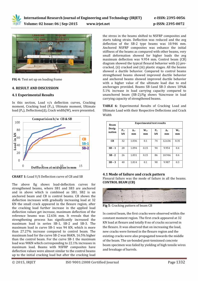
All the beams were tested statically, under loading frame of capacity of 50 T; the loading setup was as shown in Fig 4. The deflection was measured at mid span of the beams. The load is applied at a 2 kN increment up to ultimate load. At each increment of load, deflections were noted.
International Research Journal of Engineering and Technology (IRJET) e-ISSN: 2395-0056
Volume: 02 Issue: 06 | Sep-2015 www.irjet.net p-ISSN: 2395-0072
© 2015, IRJET ISO 9001:2008 Certified Journal Page 1332
FIG 4: Test set up on loading frame
4. RESULT AND DISCUSSION
4.1 Experimental Results
In this section, Load v/s deflection curves, Cracking moment, Cracking load (Pcr), Ultimate moment, Ultimate load (Pu), Deflections(Δ), Crack width(W), were presented.
CHART 1: Load V/S Deflection curve of CB and SB The above fig shows load-deflection curves for strengthened beams, where SB1 and SB3 are anchored and in above which is combined as SB1. SB2 is un anchored beam and CB is control beams. CB shows the deflection increases with gradually increasing load at 32 KN the small crack appeared in the flexure region, after the cracking load further increase in the applied load deflection values get increase, maximum deflection of the reference beams was 12.636 mm. It reveals that the strengthening process has significantly increased the maximum load in series SB-1, SB-2 and SB-3. The maximum load in curve SB-1 was 94 KN, which is more than 27.27% increase compared to control beam. The maximum load for the curve SB-2 was 86KN, 16.5% higher than the control beam. For the curve SB-1 the maximum load was 90KN which corresponding to 22.1% increases in maximum load. Beams with NSFRP composites have deflection values were almost similar to the control beams up to the initial cracking load but after the cracking load
the stress in the beams shifted to NSFRP composites and starts taking strain. Deflection was reduced and the avg deflection of the SB-2 type beams was 10.946 mm. Anchored NSFRP composites was enhance the initial stiffness of the beams as compared with other beams, very small deformation showed for higher loads the avg maximum deflection was 9.954 mm. Control beam (CB) diagram showed the typical flexural behavior with (i) pre-cracked, (ii) cracked and (iii) plastic stages. All the beams showed a ductile behavior. Compared to control beams strengthened beams showed improved ductile behavior and anchored beams showed improved ductile behavior with a higher value of the ultimate load due to end anchorages provided. Beams SB-1and SB-3 shows 10%& 5.1% increase in load carrying capacity compared to unanchored beam (SB-2).Fig shows %increase in load carrying capacity of strengthened beams.
TABLE 6: Experimental Results of Cracking Load and
Ultimate Load with their Respective Deflections and Crack
Width
Beam
Desig-
nation
Experimental test results
Pcr
kN
Δcr
mm
Wcr
mm
Pu
kN
Δu
mm
Wu
mm
CB 32 1.036 0.1 74 12.636 0.35
SB – 1 28 1.094 0.15 94 9.954 0.4
SB - 2 26 1.831 0.15 86 10.946 0.4
SB – 3 40 1.814 0.1 90 9.987 0.3
4.1 Mode of failure and crack pattern Flexural failure was the mode of failure in all the beams. CONTROL BEAM (CB)
Fig 5: Cracking pattern of beam CB
In control beam, the first cracks were observed within the
constant moment region. The first crack appeared at 32
KN load at flexure and totally 8 no of cracks occurred in
the flexure. It was observed that on increasing the load,
new cracks were formed in the flexure region and the
existing cracks were also propagated towards the middle
of the beam. The un-bonded post-tensioned concrete
beam specimen was failed by yielding of high tensile wires
and breakage of barrels.

International Research Journal of Engineering and Technology (IRJET) e-ISSN: 2395-0056
Volume: 02 Issue: 06 | Sep-2015 www.irjet.net p-ISSN: 2395-0072
© 2015, IRJET ISO 9001:2008 Certified Journal Page 1333
SB-1
Fig 6: Cracking pattern of beam SB -1
First crack appeared at 44 KN, length and average spacing was more compared with CB. Total no of cracks were more compared with CB beams.12 no of cracks occurred in flexure. Average length of the F.C was 100 mm and widening of the flexural cracks was restricted by the NSFRP.
SB-2
Fig 7: Cracking pattern of beam SB-2 First cracks appeared at 38 KN load ,the flexural-shear cracks propagates towards the loading points, 9 no of cracks occurred in flexure and maximum no of cracks appeared in flexural shear zone length of the cracks were more when compared with the control beams, the crushing of the concrete was found at the loading points.
SB-3
Fig 8: Cracking pattern of beam SB-3
First crack occurred almost 40 KN, Total no of cracks were more compared with all other beams.13 no of cracks occurred in both F.C average length of the F.C was 110 mm .In this case widening of the flexural cracks was restricted by the CFRP laminates and its extend the no of cracks in the F.S.C.
5. CONCLUSIONS
Based upon the test results and observations of the experimental study undertaken the following conclusions have been drawn.
1. The ultimate load carrying capacity of the strengthened beams was found to be increased by 16.5% compared to control beams.
2. The ultimate load carrying capacity of the anchored beams was found to be increased by 27.27% compared to control beams.
3. Providing the mechanical anchorage to NSFRP composite the load carrying capacity was found to be increased by 10% compared with beams without anchorage.
4. From the test results and observations found that role of the anchorages is to transform a brittle type of failure into a more ductile failure and generally PT beams are more ductile than RC beams. .
5. Stiffness is more in anchored and unanchored compared to CB.
6. Ductility index ratio is more in control beams where it was 83% in SB-1, 74.2% in SB-2, and 80.04% in SB-3compare to strengthened beams.
7. Strain is well within the limit for strengthened beams compared to control beams.
8. Overall stiffness of the strengthened beams was found to be more compared with the control beams.
9. No de-lamination of NSFRP composite occurred in both anchored and unanchored beams.
REFERENCES
1. Habibur Rahman Sobuz, Ehsan Ahmed, “Use of
carbon fiber laminates for strengthening
reinforced concrete beams in bending”,
international journal of civil and structural
engineering, Volume 2, No 1, 2011
2. C. Pellegrino & C. Modena,(2012) “Flexural
behavior of RC and PC beams strengthened with
external pretension FRP laminates” Department
of Constructions and Transportation Engineering,
University of Padova, Padova, Italy.
3. Majid Ali (2010), “Coconut fibre – A Versatile
material and application in engineering”, Second
international conference on sustainable
construction materials and technologies, June28-
June 30,2010
4. Kuruvilla Joseph1, Romildo Dias Tolêdo Filho2,
Beena James3, Sabu Thomas4 & Laura Hecker de
Carvalho5(1999), “A review on sisal fibre
reinforced polymer composites”, Revista
Brasileira de Engenharia Agrícola e Ambiental,
v.3, n.3, P.367-379, 1999 Campina Grande, PB,
DEAg/UFPB.
5. Mohd Zamin Jumaat, M. D. Ashraful Alam (2010),
“Experimental and numerical analysis of end
anchored steel plate and CFRP laminate flexural
strengthened reinforced concrete (r. c.) Beams”

International Research Journal of Engineering and Technology (IRJET) e-ISSN: 2395-0056
Volume: 02 Issue: 06 | Sep-2015 www.irjet.net p-ISSN: 2395-0072
© 2015, IRJET ISO 9001:2008 Certified Journal Page 1334
International Journal of the Physical Sciences Vol. 5
(2), pp. 132-144, February, 2010.
6. IS: 456-2000, Plain And Reinforced Concrete -
Code Of Practice.
7. IS: 1343 – 1980, Code Of Practice For Pre-stressed
Concrete.
8. ACI 318M-08, Building Code Requirements for
Structural Concrete (ACI 318M-08) and
Commentary.
9. IS: 10262:2009, Recommended Guidelines For
Concrete Mix Design.
10. IS: 383-1970, Specification For Course And Fine
Aggregates From Natural Sources For Concrete.
11. ACI 440.2R-2002, Guide for the design and
construction of externally bonded FRP systems
for strengthening concrete structures.