stress analysis of haunch region in a rigid-frame...
TRANSCRIPT

by 32 percent, but the combination of the two reduces the deflection by only 45 percent.
The moments in the stiffening truss are reduced at the quarter points of the main span and the center of the side span in all schemes. At the center of the main span, the moments increase up to 15 percent when diagonals are used, but less when other schemes are used.
The costs of the various schemes are given below.
Scheme
Tie cables Diagonals and stays Side-span supports
COMMENTS
Cost($)
4 000 000 10 250 000 4 750 000
The question that many may ask is, Why use a model when a computer can do the work more easily? The computer can do the job more economically than a
19
model for a specific condition or p1·oblem. In this case, however, we had some general ideas of what we wanted to try a11d thought that simply working with the model would generate additional ones.
Again you may ask, Why use a single-plane model to study ways to reduce torsional deflections? A threedimensional model would have cost at least four times as much, because of the problems of duplicating the details and behavior of the floor beams and the bottom lateral system in the transverse and vertical planes. Also, we felt at the time that we could reduce the torsion by some means of resisting the change in the cable curve.
ACKNOWLEDGMENT
The model tests were made at Columbia University. I thank J. M. Garre Us, who made a space large enough to accommodate the model available to us.
Publication of this paper sponsored by Committee on Steel Bridges.
Stress Analysis of Haunch Region in a Rigid-Frame Bridge S. D. Leftwich and F. W. Barton, University of Virginia and Virginia Highway and
Transportation Research Council, Charlottesville
The primary purpose of this study was to develop an analytical model of the haunch region of a Tigid-frame bridge, including the associated methodology for stress analysis, and to determine the magnitude and distribution of the stresses in a typical haunch configuration. A finiteelement model was adopted for the haunch configuration, and loadings were determined from an analysis of the entire frame. Stresses and displacements throughout the haunch region were calculated for various live-load locations. The stresses in the web and flanges were compared with experimentally measured stresses available from a field test of the actual structure on which the analytical model was based. The comparison tended to validate the reliability of the model and method of analysis. Subsequent stress analyses were conducted to study the effect of including stiffeners in the haunch. The effects of web and flange thicknesses on the stress distribution in the haunch were also examined. Although only one bridge configuration and haunch geometry was considered, it is believed that the results of this study can be readily extrapolated to other haunch configurations in other rigid-frame bridges.
The use of rigid-frame structures for highway bridges is becoming increasingly popular. Bridges of this type generally have multi.span, welded rigid frames and are so called because the supporting legs are integrally framed with the welded haunched girders that support the deck. In the analysis and design of such structures, it is necessary to make certain idealizing assumptions so that a reasonably uncomplicated solution may be achieved. These assumptions include (a) selecting effective lengths and stiffnesses for 11onp1·ismatic members, (b) idealizing the support conditions, and (c) making rather substantial simplifications that will permit the analysis of stresses in the haunch regions of the frame. Although certain of these assumptions can be made on a rational basis and have been shown to give
reliable results, others are less reliable and the resulting solution is subject to question.
In the design of the haunch, accurate predictions of the stresses in the web under the design load are essential to ensure that AASHO specifications against buckling are satisfied and to determine the need and location for stiffeners. The application of traditional analysis and design procedures to this complex problem leads to results whose reliability and accuracy are uncertain. Thus, it seems desirable to develop a more accurate methodology for the prediction of haunch stresses by using contemporary analysis tools such as the finite-element method.
OBJECTIVE
The broad objective of this study was the development of a realistic model of the haunch region of a rigid-frame bridge element that would permit an accurate and reliable determination of the stresses within the haunch. The development of such a model would make possible subsequent parametric stress-analysis studies for the evaluation of the effects of geometry, stiffener location, and flange and web thicknesses on stress levels and locations cif peak stresses within the haunch. The results of experimental stress measurements in the haunch region of a rigid-frame bridge, determined in earlier tests, were used as a basis of comparison for verifying the model.
Within the broad objective of the investigation, the following specific tasks were established:
20
1. The development of a rea!Lstic analytical model of the haunch region of a. rigid-frame highway bridge that would permit accUl·ate determination of stresses·
2. The determination of loadings on the haunch, corresponding to actual vehicle loads, by using standard modeling techniques for the entire bridge;
3. The calculation of the stress levels throughout the haunch for various vehicle locations;
4. The comparison of these analytical values of stress with those determined experimentally to provide some measure of verification of the haunch model; and
5. The evaluation of the effects of haunch parameters, such as stiffeners and thicknesses of the webs and flanges, on stress levels and peak stress locations.
The investigation was limited to the study of one bridge configuration and haunch geometry; namely, that of the rigid-frame bridge on I-64 near Charlottesville, Virginia. This particular bridge was chosen because it had recently been the subject of an extensive field study, and the results of the experimental stress and deflection measurements were available. The haunch co1lfigw·ation in tltis bridge is similar to that found in other rigidframe structures, and .the results of this study could be readily extrapolated to other haunch configurations. Because all of the experimental stress and deflection measurements correspond to a single vehicle load, the same live load was used throughout the study. The haunch parameters included were the thicknesses of the web and flange and the presence and absence of stiffeners in the haunch.
DESCRIPTION OF BRIDGE
The bridge studied carries the westbound lane of I-64
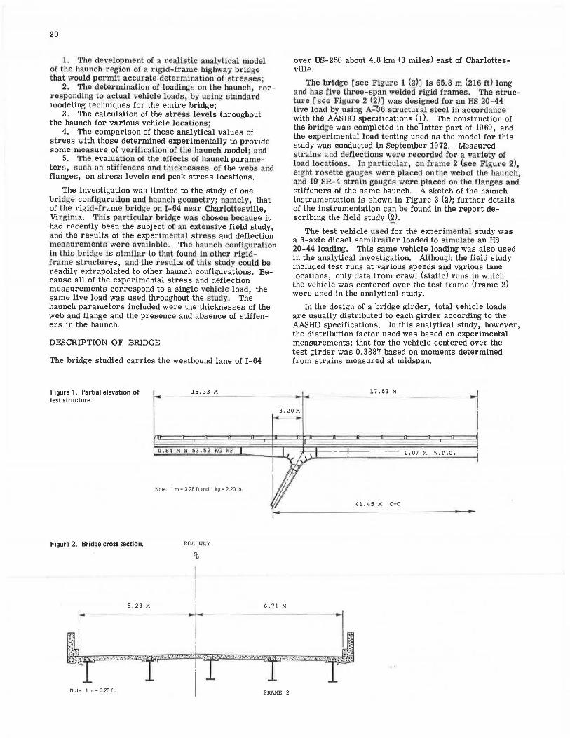
Figure 1. Partial elevation of test structure.
Figure 2. Bridge cross section.
15.33 M
0.84 M x 53.52 KG ~IF
Note: 1 m = 3.28 ft and 1 kg= 2.20 lb.
ROADWAY
over US-250 about 4.8 km (3 miles) east of Charlottesville.
The bridge [ see Figure 1 {!)J is 65.8 m (216 ft) long and has five three-span welded rigid frames. The structure [see Figure 2 (2)J was designed for an HS 20-44 live load by using A~6 structural steel in accordance with the AASHO specifications (1). The construction of the bridge was completed in the latter part of 1969, and the experimental load testing used as the model for this study was conducted in September 1972. Measured strains and deflections were recorded for a variety of load locations. In particular, on frame 2 (see Figure 2), eight rosette gauges were placed on the web of the haunch, and 19 SR-4 stuin gauges were placed on the flanges and stiffeners of the same haunch. A sketch of the haunch instrumentation is shown in Figure 3 (2); further details of the instrumentation can be found in the report describing the field study (!).
The test vehicle used for the experimental study was a 3-axle diesel semitrailer loaded to simulate an HS 20-44 loading. This same vehicle loading was also used in the analytical investigation. Although the field study included test runs at various speeds and various lane locations, only data from crawl (static) runs in which the vehicle was centered over the test frame (frame 2) were used in the analytical study.
In the design of a bridge girder, total vehicle loads are usually distributed to each girder according to the AASHO specifications. In this analytical study, however, the distribution factor used was based on experimental measurements· that for the vehicle centered over the test girder wa~ 0.3887 based on moments determined from strains measured at midspan.
17.53 M
3. 20 M
-tr--- - -- 1.07 M W.P.G.
41. 45 M C-C
5.28 M 6,71 M
~'·W>•-• .... ,1~*·''"'"'11 "i•'ifc\,iJ·.•c;:. .•.·)F.iRAM·. ~~·'·"" •'-~~ Note: 1 m = 3~28 ft_

Figure 3. Haunch gauge locations.
Figure 4. Finite-element model of haunch.
U2
ANALYTICAL MODEL OF HAUNCH REGION
2.13 M
Rl , R2 J!::]
The upper portion of the haunch region of the rigid frame consists of a 0.203-m (8-in) concrete deck that overlays the top flange and is connected by studs to ensure composite action. A finite-element model was adopted as the analytical representation of the haunch. In the initial phase of the study, a number of mesh sizes a1ld configurations were examined; the rrtodel finally adopted is depicted in Figure 4. The small crosses at the centroids of certain web elements indicate the locations of strain
l. 51 M
- STRAIN GAGE
~ ROSETTE IL
Note: 1 m :: 3.28 ft.
21
gauges on the actual bridge. Only four basic elements were used in the finite-element model of the haunch. Beam elements were used to represent the top steel flange and the concrete upper deck, bar elements were used to represent the stiffeners, the web region was modeled by using membrane elements, and the lower flanges of the haunch were represented by platemembrane elements. Details of these elements can be found elsewhere (3).
Theoretically, the finite-element model of the haunch should require no support conditions for equilibrium, but, to prevent rigid body motion, the following support

22
conditions for the haunch region were imposed: (a) a pinned support at the middle node of the leg extremity (point A in Figure 4) and (b) a roller support at the lowest node of the haunch interior (point B in Figure 4). This method of supporting the haunch model seems rational because the legs were assumed to be pinned and the bearings at the abutments were taken as rollers in the bridge finite-element program.
DETERMINATION OF LOADS ON HAUNCH MODEL
The external loads applied to the haunch extremities correspond to internal forces at the haunch locations in the frame for a particular location of live load. These loadings on the haunch thus require an analysis of the entire frame, which was performed by using standard finite-element modeling in which the frame was represented as a series of prismatic beam elements.
This particular bridge model was also used in the earlier study of the bridge (2). In this model, the flexural characteristics of the structure were modeled as closely as possible. The concrete deck was transformed to an equivalent nrea of steel by ush1:; ::i value of n (ratio of E,/E0 ) equal to 6 and an effective slab width p1·escribed by AASHO specifications. The composite section was used in negative moment areas as well as in positive moment areas inasmuch as there was no apparent cracking in the deck slab. For support conditions, each of the inclined legs was assumed to be pinned at the base and the bearings at the abutments were treated as roller supports. The results of the analytical study compare favorably with the experimental results (2), thus indicating a reliable model. The results used in this comparison were based on the vehicle centered over the test frame and a transverse distribution factor of 0.3887, which was the experimentally measured distribution factor based on the midspan moments.
By using a live load corresponding to an AASHO HS 20-44 vehicle loading, the internal forces were calculated at frame locations corresponding to the haunch extremities for a variety of load locations; these forces were used as external loading on the haunch model. This same model was also used to define the loading at the haunch extremities caused by the dead load of the bridge.
After the external forces on the haunch were determined, they were transformed into nodal loads for use with the finite-element model. The shear and thrust forces were distributed evenly among the nodes at the haunch extremities. For the moments, an equivalent force at each node was determined by calculating the tributary area about the node in question multiplied by the average stress. The average si;res:; auuuL a uuue was obtained by evaluating the stress between adjacent nodes and taking the average of the two values.
Figure 5. Vehicle at location 28 percent. 12. 27 M
Note: 1 m =- 3,28 ft .
RESULTS OF STRESS ANALYSIS OF HAUNCH
Stresses Caused by Live Loads
The haunch model was analyzed by using the large, general-purpose finite-element code called SPAR (3) to determine the nodal displacements and element stresses for all of the elements in the web and flanges of the haunch. Because the stress parameter of primary interest in the web of the haunch is the absolute maximum stress, the stress output from the SPAR program was transformed into principal stresses for the web elements. This value not only gives the best indication of critically stressed regions in the haunch, but also permits direct comparison with the experimentally determined stresses (which were available only in the form of principal stresses).
Two vehicle locations (where the vehicle location is defined as the location of the front axle of the vehicle given as a percentage of the distance between the air hoses used during the experimental testing of the bridge) were used for the live-load study. These were chosen on the basis of the influence lines and the experimental data and were those at 28 and 35 percent respectively, which were believed to be the ones that would produce the maximum stresses. Thus, 28 percent of the distance between ai1· hoses is equivalent lo lhe front axle of the vehicle's being a distance of 12.2 m (40.25 ft) from the left abutment (see Figu1·es 5 and 6).
Contours of Minimum Principal Stress
The best method of representation of the stress levels within the haunch region appears to be in the form of stress contours. The minimum principal stresses are the largest in absolute value; thus, contours of these stresses were plotted for the two vehicle locations by extracting those calculated at the centi·oid of each element of the finite- element haunch model (see Figure 4) and then interpolating a smooth curve between values of equal stl·ess to obtain a contour line. All contours shown are in iutervals of 1.38 MPa (200 lbf/in2
) and for the minimum principal stress only. All stresses are in compression, and the direction of minimum stress is normal to the contour line. Stress contours were also generated for a haunch that did not have stiffeners to observe whether there were any significant changes in stress levels. To compare the contours, the stresses at three different locations within the haunch region are denoted to demonstrate the effect of the stiffeners. In all ca~e:s, tht:: haui1ch loadiugs -~~.iere calculatGd by as suming that the girders were on roller supports at the end abutments.
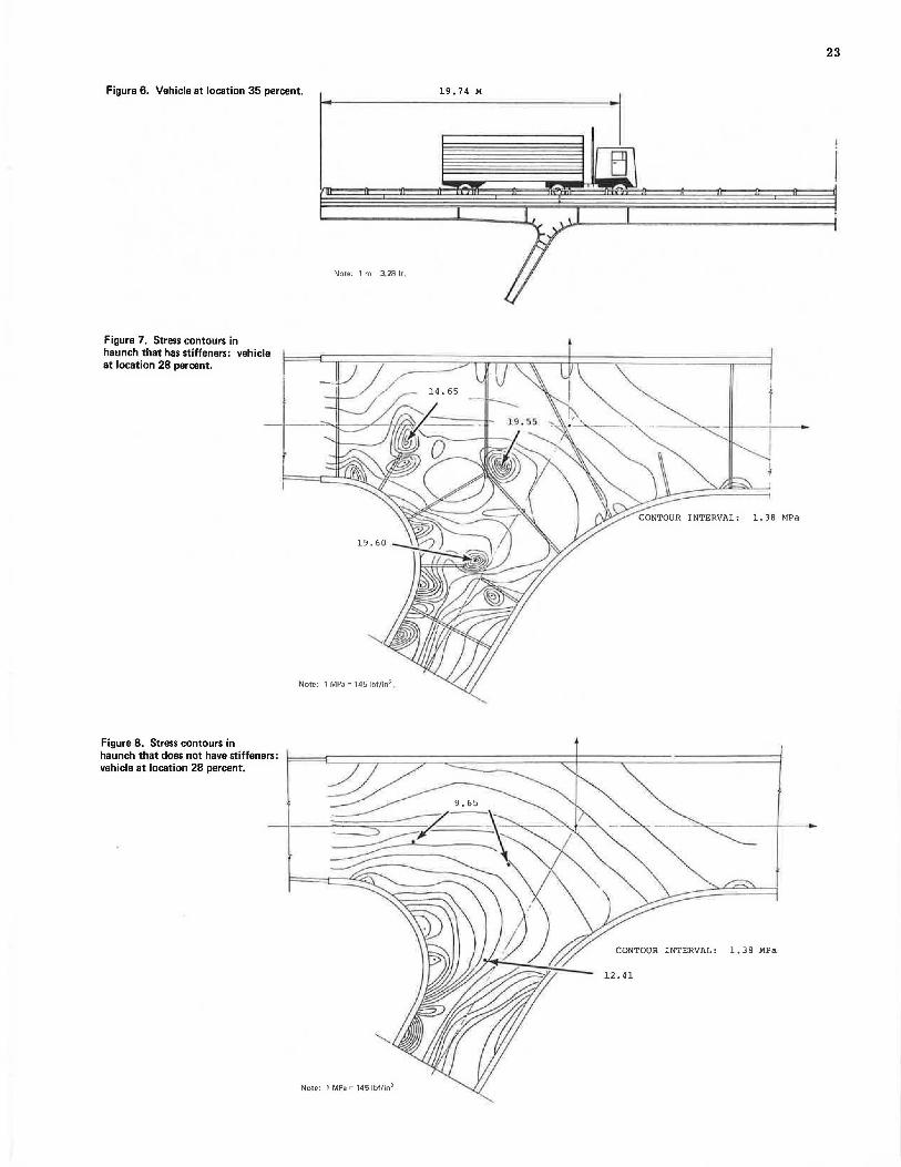
Figure 6. Vehicle at location 35 percent.
Figure 7. Stress contours in haunch that has stiffeners: vehicle at location 28 percent.
Figure 8. Stress contours in haunch that does not have stiffeners: vehicle at location 28 percent.
Note: 1 m = 3.28 ft.
19.60
Note: 1 MPa = 145 lbf/in2,
Note: 1 MPa"' 145 lbf/in2
23
19. 74 M
l.38 MPa
CONTOUR INTERVAL: l.38 MPa
12.41

24
Figures 7 and 8 show the contours of the minimum principal stress for the vehicle at location 28 percent for the haunch region in the presence and absence of stiffeners respectively. Figure 7, that for the haunch that has stiffeners, shows a concentration of stresses at three locations corresponding to the end and junctions of stiffeners; Figure 8, that for the haunch that does not have stiffeners, has much smoother stress contours and only a few areas of stress concentration about the curved lower flange. Of particular interest is the fact that the stress levels at the three points identified in Figure 7 are significantly reduced. However, the largest compressive stress for the haunch that has stiffeners was 21. 55 MPa (3126 lb!/in2
) and the largest for the haunch that does not have stiffeners was only 22.47 MPa (3259 lbf/in2l, which is an increase of only approximately 4 percent.
Figure 9. Stress contours in haunch that has stiffeners: vehicle at location 35 percent.
Figure 10. Stress contours in haunch that does not have stiffeners: vehicle at location 35 percent.
Note: 1 MPa "' 145 lbf/in 2
Note: 1 MPa = 145 lbf/in2 .
Figures 9 and 10 show the contours of the principal stress for the vehicle at location 35 percent for the haunch region in the presence and absence of stiffeners respectively. Again, there are stress concentrations at the end and junction of the stiffeners in Figure 9, but only a few areas of high stress concentration for the haunch region that does not have stiffeners (see Figure 10). The stress levels at two of the three designated locations within the haunch were reduced significantly by the deletion of the stiffeners. The largest compressive stress in the haunch that has stiffeners was 21. 70 MPa (3147 lbf/ in2
) and the largest for the haunch that does not have stiffeners was 24.24 MPa (3516 lbf/ in 2
),
an increase of about 12 percent. Figures 7 through 10 indicate that the inclusion of
stiffeners in the haunch region of the bridge may lead to areas of high stress concentrations at the end and
CONTOUR INTERVAL: 1.38 MPa
'~----::->
CONTOUR INTERVAL: 1.38 MPa

junctions of the stiffeners . These figures also indicate that the deletion of stiffeners altogether within the haunch appears to produce fewer areas of high stress concentration and smoother flow patterns of the stress contours. They also show that the absence of stiffeners does not necessarily increase the minimum compressive stress in all regions of the haunch web. If stiffeners are used, such areas of high stress concentration may be particularly susceptible to fatigue-type failures in the welds joining the stiffeners to the web. Thus, the use of stiffeners may have detrimental results in the web portion of the haunch and care should be exercised in the de-sign of the haunch with regard to the use and placement of the stiffeners .
Effect of Web and Flange Thickness on Stress Levels
A number of analyses were made of the finite-element model of the haunch that had stiffeners for various web and flange thicknesses and the vehicle at location 28 percent. The flange thicknesses r anged from 2. 54 to 50.8 cm (1.0 to 2.0 in), and the web thicknesses were var ied from 0.95 to 1.27 cm (%to 1/a in) . There appeared to be no recognizable pattern of stress magnitudes; the highest stresses occurred in different regions for the various web and flange thicknesses . Generally, for a constant flange thickness, the stresses in almost all regions of the haunch focreased as the web became thinner-which is an expected result. A noteworthy observation was that, for a constant web thickness, the stress levels in all regions of the haunch did not necessarily increase as the flange thickness decreased. One possible explanation of this phenomenon could be the redistribution of stresses caused by the reduction in the thickness of the flange.
Stresses Caused by Dead Loads
The analysis of the haunch stresses caused by live loads indicated regions of stress concentration that might pos-
Table 1. Experimental and analytical live-load stresses in haunch web at gauge locations.
Vehicle at Vehicle at Location Location 28 35 Percent Percent: Ana-lytical Stress Analytical Stress (MPa l Experi- (MJ>n)
mental Rosette Principal Roller Pinned Stress Roller Pinned Gauge Stress Support Support (MPa) Support Support
Rl a min -6. 78 -5.66 -2.99 -6. 89 -3 .08 and a max 1.23 0.66 1. 79 2.43 0. 81 R2 r max 4.01 3.16 2.39 4. 66 1.94
R3 a min -14 .65 -12.98 -7 .55 -13 .40 -7 ;51 a max -1.21 -1.61 -3 .15 0.48 -0. 66 T max 6.72 5.68 2.20 6.94 3.43
R4 a min -10.37 -9 .62 -10 .02 -9 .16 -6.17 a max 7.65 6,42 1.14 5. 81 1.32 T max 9.01 8.02 5.58 7.48 3.75
R5 a min -13.83 -12.56 -9 . 78 -13 .13 -8.48 a max 0.99 0 . 58 -0 .85 0.01 -1.54 T max 7. 41 6.56 4.47 6. 56 3.47
R6 a min -7.36 -6.70 -7.87 -7.76 -4.67 a max 4.14 3.40 0.97 3. 78 0 .62 T max 5.76 5.05 4.42 5. 76 2.65
R7 a min -2 .08 -2.12 -4 .82 -3 ,92 -3 .66 a max 0.76 0.29 -1.64 1.39 -0.26 T max 1.42 1.21 1.59 2.65 1. 70
RB a min - 2.83 - 3.30 -6.16 - 2.73 - 3.53 a max 1.32 0.55 -3.03 2.30 -0.80 T max 2.08 1.92 1.57 2.52 1.37
Note : 1 MPe - 145 lbf/ in'.
25
sibly be stressed beyond the allowable limit when the total dead load plus the live load was considered . Hence, a limited study was made to determine the approximate peak stresses in the haunch when the effect of dead loads was included.
For the haunch that had stiffeners, the minimum principal compressive stress caused by dead loads was 67.46 MPa (9784 lbf/in2
) for the bridge on roller supports at the end abutments and, for the haunch that did not have stiffeners, the largest stress was 76. 72 MPa (11 127 lbf/in2
). Correspondingly, the la r gest live-load s tres s es were 21.70 MPa (3147 lbf/ in2
) and 24.24 MPa (3 51 6 l bf/ in3
) for t he haunch that did and t he haunch that did not have stiffeners respectively. The worst possible combination of dead load plus live load for these two cases would be s imply the su m of the two-i.e., approximately 89.64 MPa (13 000 lbf / in2
) and 101.36 MPa (14 700 1bf/i n2
) in compr ession- which are well below the maximum allowable stress of 137.90 MPa (20 000 lbf/ in2
).
Another observation was that the dead-load stresses determined from computer runs based on the assumption of pin supports at the end abutments were all lower in magnitude than the r esults based on the assumption of roller supports . A possible explanation for this effect is that the internal forces about the haunch extremities are changed significantly whenever the horizontal movement of the bridge is restricted.
DISCUSSION OF RESULTS
The determination of stresses in the haunch region ca.used by live and dead loads given above provides a basis for comparison with experimentally measured stresses.
In Table 1, the principal stresses in the web obtained in the experimental study are compared with those determined in the finite-element analysis. Both support conditions of the bridge at the end abutments were considered. Unfortunately, there were no experimental results available for the vehicle at location 28 percent.
As shown in Table 1, most of the analytical results compare favorably with the experimental results . The latter appear to be bounded by the former for pinned and roller supports at the end abutment. The experimental stresses do, however, appear to agree more closely with the analytical stresses for the pinned support, rather than for the roller SLtpport. For the live load considered, it appears that there may be some restriction of the horizontal movement of the bridge at the end abutments. This could be caus ed by either of two rea -sons: (a) frictional resista nce of the girder against the bearing plate at the end abutments might r estrict horizontal movement or (b) the r elative magnitude of the live load might be so small, in comparison with the dead load, that most of the lateral movement of the bridge would be taken up by the rotation of the legs at the interior supports.
In Table 2, the stresses determined in the experimental and analytical studies a.re compared for the gauges on the upper and lower flanges and on the stiffeners. At locations 28 and 35 per cent, the results of the analytical study compare satisfactorily with the experimental results for some gauges, but not favorably for the others. This discrepancy of the live-load stresses may be the result of a number of factors.
For example, the experimental results were measured manually from oscillograph tapes, and some discrepancies in the peak values of the stresses may have been introduced. Still, it is probable that these experimental values represent a good approximation to the actual values. Also, the stresses obtained at vehicle

26
Table 2. Experimental and analytical live-load stresses in haunch flanges at gauge locations.
Vehicle at Vehicle at Location Location 28 35 Percent Percent: Ana-lytlcnl Stress An.'llylical Stress
Expert- (MP~) Expert- (MPa) mental mental Stress Roller Pinned Stress Roller Pinned
Gauge (MPa) Support Support (MPa) Support Support
L2 0.52 -5.71 - 5.37 -2.85 -4.40 -3.12 L3 -11.40 -7 .36 -6.62 -7.07 -6.29 -3.63 L4 -15.97 -9.09 -7.83 -9.08 -8.72 -4.39 L5 -9.86 -4.19 -3.52 -6. 18 -4.19 -1.90 L6 3.91 3.70 2.90 -2.94 3.08 0 .34 L7 3.21 7.58 5.76 -3.44 5.98 -0.26 LS -0.90 3.43 1.99 -4, 54 2.76 -2.23 L9 -3 .64 0.11 -1.09 -5.94 0.99 -2.91 LIO -3 .94 -1.53 -2. 76 -5.21 1.10 -2.82 Lll -3 .97 -0 . 57 -3.67 -3.11 0.41 -0.68 U2 0.46 0.43 0,49 0 0.25 0.51 U3 -0.33 -0.36 -0.23 0 -0.90 -0.37 U4 -0.12 0.40. 0.46 -0.34 1.24 1.51 U5 0 0 .43 0.64 0 -0.38 0.39
Note: 1 MPa " 145 lbf/in'.
locations 28 and 35 percent may be sensitive to the degree of restraint of the legs of the bridge. The bridge used for the analytical results models the legs as being pinned at their base, which appears to be a rational assumption, but the actual degree of restraint of the legs is not known.
Despite the variations between some of the experimental and analytical stresses, the agreement for the most part was surprisingly good. Factors that could not adequately be incorporated into the analytical model, such as residual stresses resulting from fabrication and induced loads transmitted through the diaphragms, may have caused some of the variations. Nevertheless, the calculated stresses were of the same order of magnitude as the experimental values, and when stresses were also calculated by using slightly different assumptions for the model, the analytical stresses frequently bounded the experimental values.
Thus, the haunch model developed in this study appears to provide an accurate representation of the actual structure and may be used with confidence for stress analyses of future similar structures.
CONCLUSIONS
The stresses determined in the analytical study compared reasonably well with corresponding stresses measured experimentally in both the web and the flanges of the haunch. Based on these resuits, it was conciuded that the haunch model developed gives reliable stresses and can be used with confidence to study the effects of various parameters on haunch stresses.
The placement of stiffeners within the haunch region may induce areas of high stress concentration at the end and junctions of the stiffeners. This possibility could be a factor in designing against fatigue, and extreme care should be exercised in placing and locating stiffeners in the haunch region of a rigid-frame bridge. Variations in the thickness of the web had significant effects on the stress levels within the haunch, although variations in the thickness of the flange had relatively small effects. Decreasing the thickness of the web and keeping the thickness of the flange constant generally increased the stress levels in the web of the haunch. There was no recognizable pattern of stress distribution when the thickness of the flange was varied and the thickness of the web kept constant.
Although only one bridge configuration and haunch geometry were considered in the study, it is believed that the results can be readily extrapolated to other rigid-frame bridges and haunch configurations.
ACKNOWLEDGMENTS
The research reported here was conducted under the general supervision of Jack H. Dillard of the Virginia Highway and Transportation Research Council. W. T. McKeel Jr., and H. L. Kinnier offered valuable suggestion~ during the analytical study and the preparation of the paper.
We acknowledge the assistance of the research council and the Federal Highway Administration in making available the experimental results from the field testing of the rigid-frame bridge modeled in the study. The assistance of personnel in the data section of the council and at the computer center of the University of Virginia is gratefully acknowledged. Finally, special appreciation is expressed to those many individuals who assisted in the preparation of the paper, in particular to Paul Hughes and Allen Baker for the graphics.
The opinions, findings, and concl_usions ar.e ours and not necessarily those of the sponsor111g agencies.
REFERENCES
1. Standard Specifications for Highway Bridges. AASHO; 1965,
2. H. L. Kinnier and F. W. Barton. A Study of a Rigid- Frame Highway Bridge in Virginia. Virginia Highway and Transportation Research Council, Cha1·lottesville, Rept. VHTRC 75-R47, April 1975.
3. W. D. Whetstone. SPAR Structural Analysis System Reference Manual. System Level 7, Lockheed Missiles and Space Company, Palo Alto, CA, June 1974.
Publication of this paper sponsored by Committee on Dynamics and Field Testing of Bridges.