stress and strain in flexible pavement
DESCRIPTION
Design considerations in flexible pavementTRANSCRIPT

Pavement Engineering
Stress and Strain in flexible Pavements
1

Flexible pavements
• Flexible pavements were classified by apavement structure having a relatively thinasphalt wearing course with layers of granularbase and subbase being used to protect thesubgrade from being overstressed.
• This type of pavement design was primarilybased upon empiricism or experience, withtheory playing only a subordinate role in theprocedure.
2

Flexible pavements…• However, the recent design and construction
changes brought about primarily by heavierwheel loads, higher traffic levels and therecognition of various independent distressmodes contributing to pavement failure (suchas rutting, shoving and cracking) have led tothe introduction and increased use ofstabilized base and subbase material.
3

HOMOGENEOUS MASS• The simplest way to characterize the behavior of
a flexible pavement under wheel loads is toconsider it as a homogeneous half-space .
• A half-space has an infinitely large area and aninfinite depth with a top plane on which the loadsare applied .
• The original Boussinesq (1885) theory was basedon a concentrated load applied on an elastic half -space. The stresses, strains, and deflections dueto a concentrated load can be integrated toobtain those due to a circular loaded area .
4

HOMOGENEOUS MASS• The theory can be used to determine the
stresses , strains, and deflections in thesubgrade if the modulus ratio between thepavement and the subgrade is close to unity,as exemplified by a thin asphalt surface and athin granular base.
5

Stress
• Force per unit area
• Units: MPa, psi, ksi
• Types: bearing, shearing , axial
PA
s = LoadArea
=
6

Strain• Ratio of deformation caused by load to the original
length of material
• Units: Dimensionless
Change in Length
Original Length e =
DL
L=
7

Deflection (D)
• Change in length.
• Deformation.
• Units: mm or linear
D

Components of stressunder axisymetricloading
9
Figure shows a homogeneoushalf-space subjected to a circularload with a radius a and auniform pressure q.The half-space has an elasticmodulus E and a Poisson ratio v .A small cylindrical element withcenter at a distance z below thesurface and r from the axis ofsymmetry is shown .Because of axisymmetry, thereare only three normal stresses,and σz, σr ,σt , and one shearstress, rz , which is equal to zr.These stresses are functions of q,r/a, and z/a .

Stresses at a point• From theory it can be shown that at a given
point within any layer, 9 stresses exist.• These stresses are comprised of 3 normal
stresses (σz, σr ,σt) acting perpendicular to theelement face and
• 6 shearing stresses
acting parallel to the face. Static equilibriumconditions on the element show that theshear stresses acting on intersecting faces areequal. Thus
(
10
Solution by charts
11
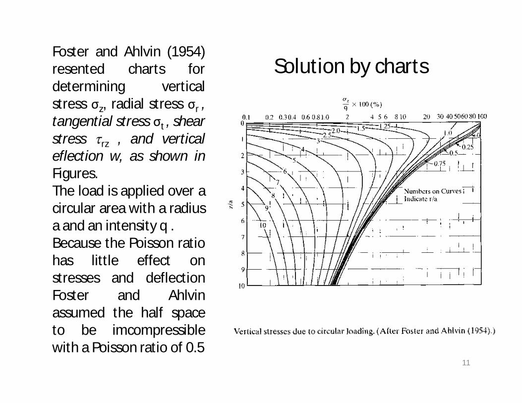
Foster and Ahlvin (1954)resented charts fordetermining verticalstress σz, radial stress σr ,tangential stress σt , shearstress rz , and verticaleflection w, as shown inFigures.The load is applied over acircular area with a radiusa and an intensity q .Because the Poisson ratiohas little effect onstresses and deflectionFoster and Ahlvinassumed the half spaceto be imcompressiblewith a Poisson ratio of 0.5

12

13

14

15

Stresses at a point
16
After the stresses are obtained from the charts, the strainscan be obtained from
If the contact area consists of twocircles, the stresses and strains canbe computed by superposition .
In applying Boussinesq's solutions, it is usually assumedthat the pavement above the subgrade has nodeformation, so the deflection on the pavement surfaceis equal to that on the top of the subgrade .

Solutions at Axis of Symmetry
17
When the load is applied over a single circular loaded area,the most critical stress , strain, and deflection occur under thecenter of the circular area on the axis of symmetry, whererz = 0 and σr = σt , so σz = σr are the principal stresses .
Flexible plateThe load applied from tire to pavement is similar to aflexible plate with a radius a and a uniform pressure q.The stresses beneath the center of the plate can bedetermined from

Solutions at Axis of Symmetry
18
Note that σz , is independent of E and v, and σz, isindependent of E. From following Eq we can get

The vertical deflection w can be determined from
19
When v = 0 .5, above Eq. can be simplified to
On the surface of the half-space, z = 0 ; from Eq .

Rigid PlateAll the above analyses are based on the assumptionthat the load is applied on a flexible plate, such as arubber tire .If the load is applied on a rigid plate, such as thatused in a plate loading test, the deflection is thesame at all points on the plate , but the pressuredistribution under the plate is not uniform.
20Differences between flexible and rigid plates.

The pressure distribution under a rigid plate can be expressed as (Ullidtz,1987 )
21
in which r is the distance from center to the point where pressureis to be determine d and q is the average pressure, which is equalto the total load divided by the area .The smallest pressure is at the center and equal to one-half of theaverage pressure . The pressure at the edge of the plate is infinity.
By integrating the point load over the area , it can be shown that the deflection of the plate is
A comparison of with above Eq. indicates that the surfacedeflection under a rigid plate is only 79% of that under thecenter of a uniformly distributed load .This is reasonable because the pressure under the rigid plateis smaller near the center of the loaded area but greaternear the edge

Nonlinear massBoussinesq's solutions are based on the assumptionthat the material that constitutes the half-space islinear elastic . It is well known that subgrade soils arenot elastic and undergo permanent deformationunder stationary loads .However, under the repeated application of movingtraffic loads, most of the deformations arerecoverable and can be considered elastic.
22
Iterative Method To show the effect of nonlinearity ofgranular materials on vertical stresses and deflections, Huang(1968a) divided the half-space into seven layers, as shown inFigure,

Nonlinear mass
23
After the stresses are obtained, the elastic modulus of each layer is determined from

in which is the stress invariant, or the sum ofthree normal stresses ; E is the elastic modulusunder the given stress invariant; E0 is the initialelastic modulus, or the modulus when thestress invariant is zero ; and is a soil constantindicating the increas in elastic modulus perunit increase in stress invariant .Note that the stress invariant should includeboth the effects of the applied load and thegeostatic stresses ; it can be expressed as
24

25
in which σz, σr and σt , 0 r, and at are thevertical, radial, and tangential stresses due toloading ; y is the unit weight of soil ; z is thedistance below ground surface at which thestress invariant is computed; and Ko is thecoefficient of earth pressure at rest.

Approximate MethodOne approximate method to analyze a nonlinearhalf-space is to divide it into a number of layersand determine the stresses at the mid height ofeach layer by Boussinesq's equations based onlinear theory.
26

• Example• Figure shows a flexible pavement surface subjected to
two circular loads, each 10 in. in diameter and spacedat 20 in. on centers. The pressure on the circular areais 50psi. Determine the vertical stress, strain anddeflection at point A, which is located 10in. below thecenter of one circle. (E=10,000 psi and a Poisson ratio=0.5).
27
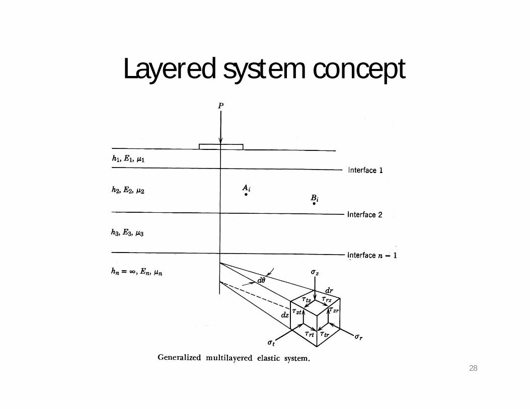
Layered system concept
28
Layred systemGenerally the analytical solution to the stateof stress or strain has several assumptions.They are:The material properties of each layer arehomogeneous, that is the property at point Aiis the same at point BiEach layer has finite thickness except for thelower layer, and all are infinite in the lateraldirections
29

Layred system…Each layer is isotropic, that is, the property ata specific point such as Ai is the same in everydirection or orientationFull friction is developed between layers ateach interfaceSurface shearing forces are not present at thesurfaceThe stress solutions are characterized by twomaterial properties for each layer. They arePoisson’s ratio µ and the elastic modulus E.
30

Two – Layer system
31

Two – Layer system• Typical flexible pavements are composed of layers
so that the moduli of elasticity decrease withdepth.
• In the solution of the two – layer problem,certain essential assumptions are made:– The materials in the layers are assumed to be
homogeneous, isotropic and elastic.– The surface layer is assumed to be infinite in
extent in the lateral direction but of finitedepth, whereas the underlying layer is infinitein both the horizontal and vertical direction.
– the layers are in continuous contact and thatthe surface layer is free of shearing and normalstresses outside the loaded area. 32

Two – Layer system…
• Stress and deflection values as obtained byBurmister are dependent upon the strengthratio of the layers, E1/E2,
• where E1 and E2 are moduli of the reinforcingand subgrade layers respectively
33

The vertical stress values under the center of a circular plate for the two-layer system
34Vertical stress distribution in a two - layer system . (After Burmister (1958) .)

35
Vertical interface stresses for two-layer systems . (After Huang (1969b) . )

36Vertical surface deflections for two-layer systems. (After Burmister (1943) )

Vertical surface deflectionVertical Surface Deflection Vertical surfacedeflections have been used as a criterion ofpavement design.Above Figure can be used to determine thesurface deflections for two-layer systems. Thedeflection is expressed in terms of the deflectionfactor F2 by
37

Vertical surface deflection
38
The deflection factor is a function of E1/E2 andh1/a. For a homogeneous half-space with h1la =0, F2 = 1, so above Eq. is identical to Eq .
when v = 0 .5 . If the load is applied by a rigid plate, then, from Eq ,

Vertical interface deflectionThe vertical interface deflection has also beenused as a design criterion.
39
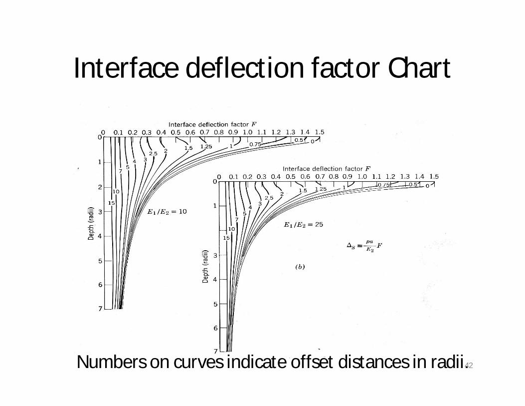
Following Figure can be used to determine thevertical interface deflection in a two-layer system(Huang, 1969c) .The deflection is expressed in terms of thedeflection factor F by

40Vertical interface deflections for two-layer systems . (After Huang (1969c) .)

Interface deflection factor Chart
Numbers on curves indicate offset distances in radii.41
Interface deflection factor Chart
Numbers on curves indicate offset distances in radii.42

Interface deflection factor Chart
Numbers on curves indicate offset distances in radii. 43

Total Surface Deflection
44

Critical tensile strainThe tensile strains at the bottom of asphalt layer havebeen used as a design criterion to prevent fatiguecracking .Two types of principal strains could be considered.One is the overall principal strain based on all sixcomponents of normal and shear stresses . The other,which is more popular, is the horizontal principal strainbased on the horizontal normal and shear stressesonly.The overall principal strain is slightly greater than thehorizontal principal strain, so the use of overallprincipal strain is on the safe side .
45

• Huang (1973a) developed charts fordetermining the critical tensile strain at thebottom of layer 1 for a two-layer system . Thecritical tensile strain is the overall strain andcan be determined from
46
in which e is the critical tensile strain and Fe is thestrain factor, which can be determined from thecharts .

Single wheelFollowing Figurepresents the strainfactor for a two-layer system undera circular loadedarea .In most cases, thecritical tensilestrain occurs underthe center of theloaded area wherethe shear stress iszero.
47

However, when both h1/a and E1/E2 are small,the critical tensile strain occurs at somedistance from the center, as the predominanteffect of the shear stress.Under such situations, the principal tensilestrains at the radial distances 0, 0.5a, a, and 1.5a from the center were computed, and thecritical value was obtained and plotted inabove Figure.
48

Dual wheels
• Because the strain factor for dual wheels with acontact radius a and a dual spacing Sd dependson Sd/a in addition to E1/E2 and hi /a, the mostdirect method is to present charts similar toabove Figure, one for each value of Sd/a .
49

Three – layer System
• Burmister’s work provided analyticalexpression for stresses and displacements inthree-layer systems.
50

• The representative three-layer pavementstructure along with the stresses that can besolved by stress factor values provided isshown in figure:
51

Three – layer pavement system
52

Solutions for the five stresses
53

• Vertical stress solutions have been obtained by Peattie and are shown in graphical form:
54
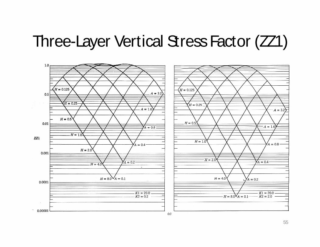
Three-Layer Vertical Stress Factor (ZZ1)
55

Three-Layer Vertical Stress Factor (ZZ2)
56

• The horizontal stress solutions have been obtained from Jones and are shown in tabular form:
57
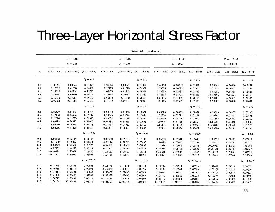
Three-Layer Horizontal Stress Factor
58

• The stress values are all along the axis ofsymmetry of a single load.
• It should be noted that the figures and the tableshave been developed for =0.5 for all layers.
• The sign convention is positive for compression.• While interpolation of the stress factor is
necessary for many problem solutions, noextrapolation is allowed.
59

• Both the vertical stress (graphical solutions) and the tabular solutions for the horizontal stresses use the following parameters.
• k1 or K1 =E1/E2 k2 or K2= E2/E1
• a1 or A =a/h2 H=h1/h2
60
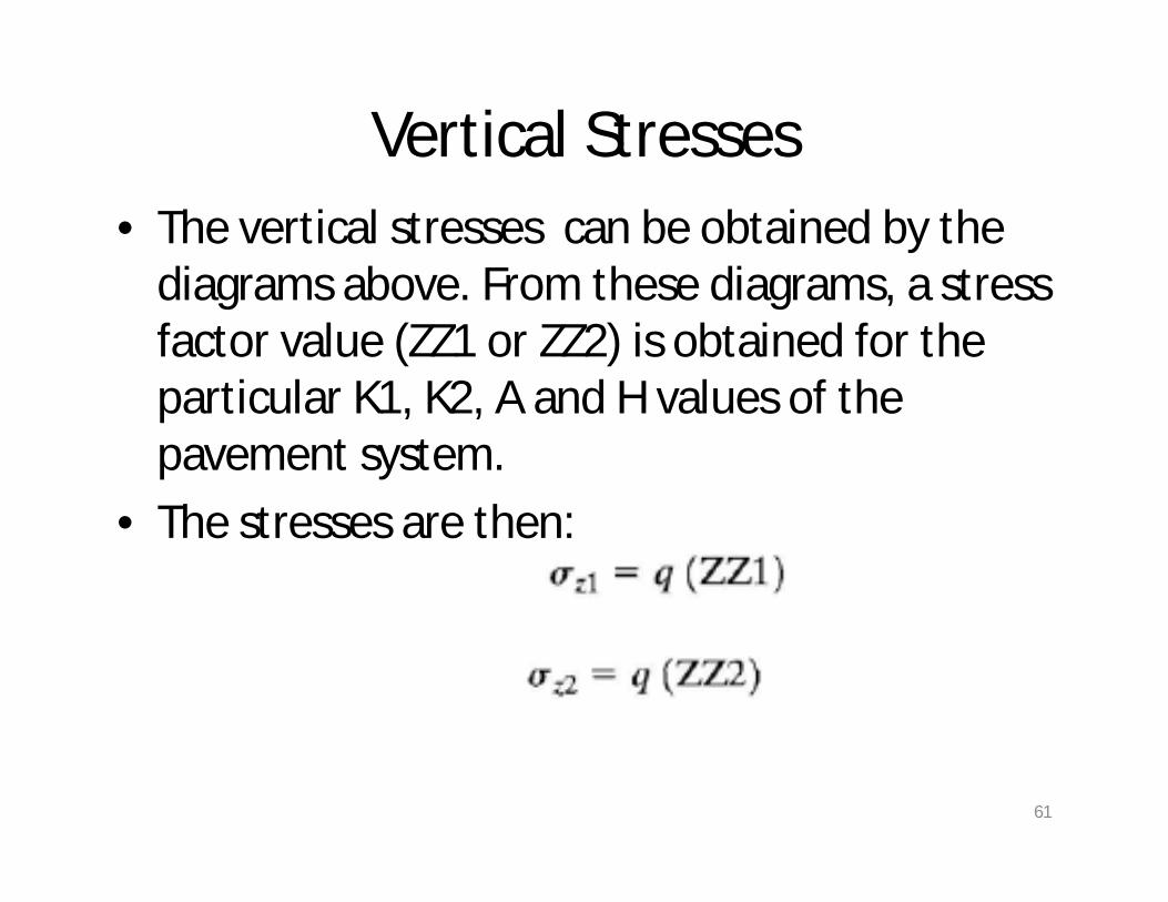
Vertical Stresses• The vertical stresses can be obtained by the
diagrams above. From these diagrams, a stress factor value (ZZ1 or ZZ2) is obtained for the particular K1, K2, A and H values of the pavement system.
• The stresses are then:
61

Horizontal stresses
62