strömungsmechanik elektronisches rechnen im bauwesen … · kröhn, k.-p. (1991): simulation von...
TRANSCRIPT
Institut für
Strömungsmechanik und
Elektronisches Rechnen im Bauwesen
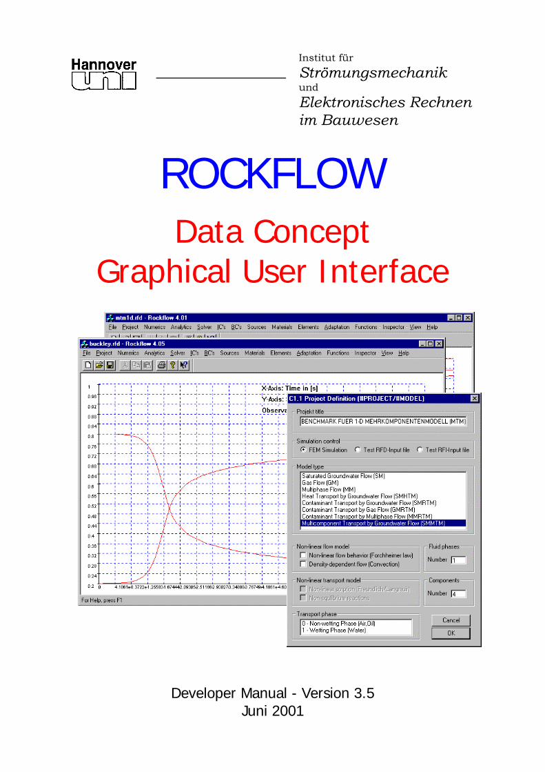
ROCKFLOW
Data Concept Graphical User Interface
Developer Manual - Version 3.5 Juni 2001

ROCKFLOW Manual – Version 3.5.04 - 12.03.04 - 10:12
ROCKFLOW
Numerical Modeling of Fluid Flow, Mass and Heat Transport in Subsurface Systems
User’s Manual Release 3.5 – Juni 2001
by
Olaf Kolditz, Abderrahmane Habbar, René Kaiser, Thomas Rother, Carsten Thorenz Martin Kohlmeier & Sylvia Moenickes
2
Contents: I RF-FEM - Theory: Governing Equations and Finite Element Formulations II RF-FEM - Data Concept and Graphical User Interface III RF-FEM - Benchmarks and Examples IV RF-HGM - Geometric Modelling and Mesh Generation V RF-HGM - Benchmarks and Examples Information on current activities and complete literature: www.rockflow.de
Acknowledgements We appreciate the following institutes for financial support in developing ROCKFLOW:
Deutsche Forschungsgemeinschaft (DFG)
Bundesministerium für Bildung, Wissenschaft, Forschung und Technologie (BMBF)
Bundesanstalt für Geowissenschaften und Rohstoffe (Dr. Liedtke, Dr. Shao, Dr. Wallner) Geowissenschaftliche Gemeinschaftsaufgaben (Prof. Dr. Clauser, Dr. Pribnow)

ROCKFLOW Manual – Version 3.5.04 - 12.03.04 - 10:12
3
Preface Previous and current work on ROCKFLOW Version 1 Wollrath, J. (1990): Ein Strömungs- und Transportmodell für klüftiges Gestein und Untersuchungen zu homogenen Ersatzsystemen. - Bericht Nr.28/1990, Universität Hannover, Institut für Strömungs-mechanik, Dissertationsschrift. Kröhn, K.-P. (1991): Simulation von Transportvorgängen im klüftigen Gestein mit der Methode der Finiten-Elemente. - Bericht Nr. 29/1991, Institut für Strömungsmechanik und Elektronisches Rechnen im Bauwesen, Universität Hannover, Dissertationsschrift. Version 2 Helmig, R. (1993): Theorie und Numerik der Mehrphasenströmungen in geklüftet-porösen Medien. - Dissertationsschrift, Bericht Nr. 34/1993, Institut für Strömungsmechanik, Universität Hannover. Shao, H. (1994): Simulation von Strömungs- und Transportvorgängen in geklüftet porösen Medien mit gekoppelten Finite-Elemente- und Rand-Element-Methoden. - Dissertationsschrift, Bericht Nr. 37/1994, Institut für Strömungsmechanik, Universität Hannover. Lege, T. (1995): Modellierung des Kluftgesteins als geologische Barriere für Deponien. - Dissertations-schrift, Institut für Strömungsmechanik und elektronisches Rechnen im Bauwesen, Universität Hannover, 213S. Ratke, R. & Kolditz, O. & Zielke, W. (1996a,b): ROCKFLOW-DM2 - 3-D Dichteströmungsmodell. - Technischer Bericht, Institut für Strömungsmechanik und Elektronisches Rechnen im Bauwesen, Universität Hannover. Kolditz, O. (1996): Stoff- und Wärmetransport im Kluftgestein. - Habilitationsschrift, Institut für Strö-mungsmechanik und Elektronisches Rechnen im Bauwesen, Universität Hannover, 392S. Barlag C. (1997): Adaptive Methoden zur Modellierung von Stofftransport im Kluftgestein. - Disserta-tionsschrift, Institut für Strömungsmechanik, Universität Hannover. Version 3 Kolditz O, Kaiser R, Thorenz C & Schulze-Ruhfus M: ROCKFLOW User’s Manual Release 3.1, June 1997, Institut für Strömungsmechanik und Elektronisches Rechnen im Bauwesen, Universität Hannover. Kolditz O, Habbar A, Kaiser R, Thorenz C: ROCKFLOW User’s Manual Release 3.2, December 1997, Institut für Strömungsmechanik und Elektronisches Rechnen im Bauwesen, Universität Hannover. Kolditz O, Habbar A, Kaiser R, Thorenz C: ROCKFLOW User’s Manual Release 3.3, November 1998, Institut für Strömungsmechanik und Elektronisches Rechnen im Bauwesen, Universität Hannover. Kolditz O, Habbar A, Kaiser R, Thorenz C: ROCKFLOW User’s Manual Release 3.4, November 1999, Institut für Strömungsmechanik und Elektronisches Rechnen im Bauwesen, Universität Hannover. Current activities and persons to contact: Olaf Kolditz Head of the groundwater modelling group, Flow of compressible fluids, heat transport (RF-GM, HTM) THM-Modelling, GUI (RF-SHELL) Abderrahmane Habbar Reactive transport (RF-RTM), Inverse Modelling Solver, Data concepts René Kaiser Grid adaptation (RF-ADP) Thomas Rother Geometric modelling, mesh generation (RF-HGM) Carsten Thorenz Multiphase and Density flow (RF-MM) Method of Characteristics, Data Filter (rf2tec) Martin Kohlmeier Deformation processes (RF-DM) THM-Modelling, GUI (RF-SHELL) Sylvia Moenickes Geometric modelling, mesh generation (RF-HGM) Associated activities concerning geometric modelling and mesh generation: Prof. Taniguchi (Okayama University)

ROCKFLOW Manual – Version 3.5.04 - 12.03.04 - 10:12
1 Data Concept
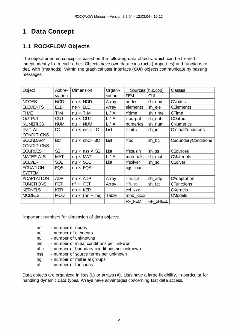
1.1 ROCKFLOW Objects The object-oriented concept is based on the following data objects, which can be treated independently from each other. Objects have own data constructs (properties) and functions to deal with (methods). Within the graphical user interface (GUI) objects communicate by passing messages. Object Abbre- Dimension Organi- Sources (h,c,cpp) Classes viation sation FEM GUI NODES NOD nn × NOD Array nodes sh_nod CNodes ELEMENTS ELE ne × ELE Array elements sh_ele CElements TIME TIM nu × TIM L / A rftime sh_time CTime OUTPUT OUT nu × OUT L / A rfoutput sh_out COutput NUMERICS NUM nu × NUM L / A numerics sh_num CNumerics INITIAL CONDITIONS
IC nu × nic × IC List rfinitc sh_ic CInitialConditions
BOUNDARY CONDITIONS
BC nu × nbc× BC List rfbc sh_bc CBoundaryConditions
SOURCES SS nu × nss × SS List rfsousin sh_ss CSources MATERIALS MAT ng × MAT L / A materials sh_mat CMaterials SOLVER SOL nu × SOL List rfsolver sh_sol CSolver EQUATION SYSTEM
EQS nu × EQS cgs_xxx
ADAPTATION ADP nu × ADP Array rfadapt sh_adp CAdaptation FUNCTIONS FCT nf × FCT Array rffunc sh_fct CFunctions KERNELS KER np × KER cel_xxx CKernels MODELS MOD nu × (nn + ne) Table mod_xxxx CModels RF_FEM RF_SHELL Important numbers for dimension of data objects:
nn - number of nodes ne - number of elements nu - number of unknowns nic - number of initial conditions per unkwon nbc - number of boundary conditions per unknown nss - number of source terms per unknown ng - number of material groups nf - number of functions
Data objects are organized in lists (L) or arrays (A). Lists have a large flexibility, in particular for handling dynamic data types. Arrays have advantages concerning fast data access.
5

ROCKFLOW Manual – Version 3.5.04 - 12.03.04 - 10:12
Construction of RF Lists The below functions create empty lists (L) or arrays (A) for all objects and destroy them. Lists are constructed only once during the program execution.
CreateObjectLists(void) DestroyObjectLists(void)
We can separate three different groups of objects. First are contained in a RFI file, second and third belong to the RFD file.
1. Geometric and topologic objects (RFI objects):
nodes (A) elements (A) adaptive elements (A) edges (A) plains (A)
2. Simulation control objects (RFD objects):
time discretization (A) output control data (L) numerical parameter (A) linear solver properties (L) non-linear solver properties (L)
3. Physical objects (RFD objects):
initial conditions (L) boundary conditions (L) source/sink terms (L) materials (L / T)
Construction of RF Objects In general, all objects are designed for numerical simulation of multiphase-multicomponental processes in porous-fractured media. Therefore, the number of objects depends on both the number of phases (number_of_phases) and the number of components (number_of_components). Additionally, the number of material groups (number_of_groups) must be specified. There are two possibilities to create RF objects. First: Reading the data from the RFD and RFI input files. The read/protocol functions -
FctObject() construct the corresponding objects. Second: Withelp of function CreateRFObjects() default objects according to the number of
phases, components and material groups can be created. Destruction of objects is conducted whether by list destruction (DestroyObjectList()) or by DestroyRFObjects() (see table below).
6
ROCKFLOW Manual – Version 3.5.04 - 12.03.04 - 10:12
Table: Object construction
Source Construction Configuration Destruction RF input files RFD and RFI
ReadData() FctObject()
- DestroyObjectLists()
RF shell CreateRFObjects() ConfigRFObjects() DestroyRFObjects() If the number of phases or components changes, objects must be configured by ConfigRFObjects().
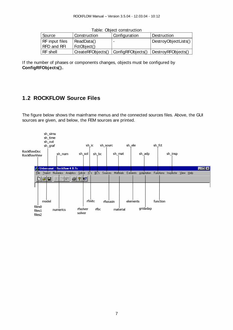
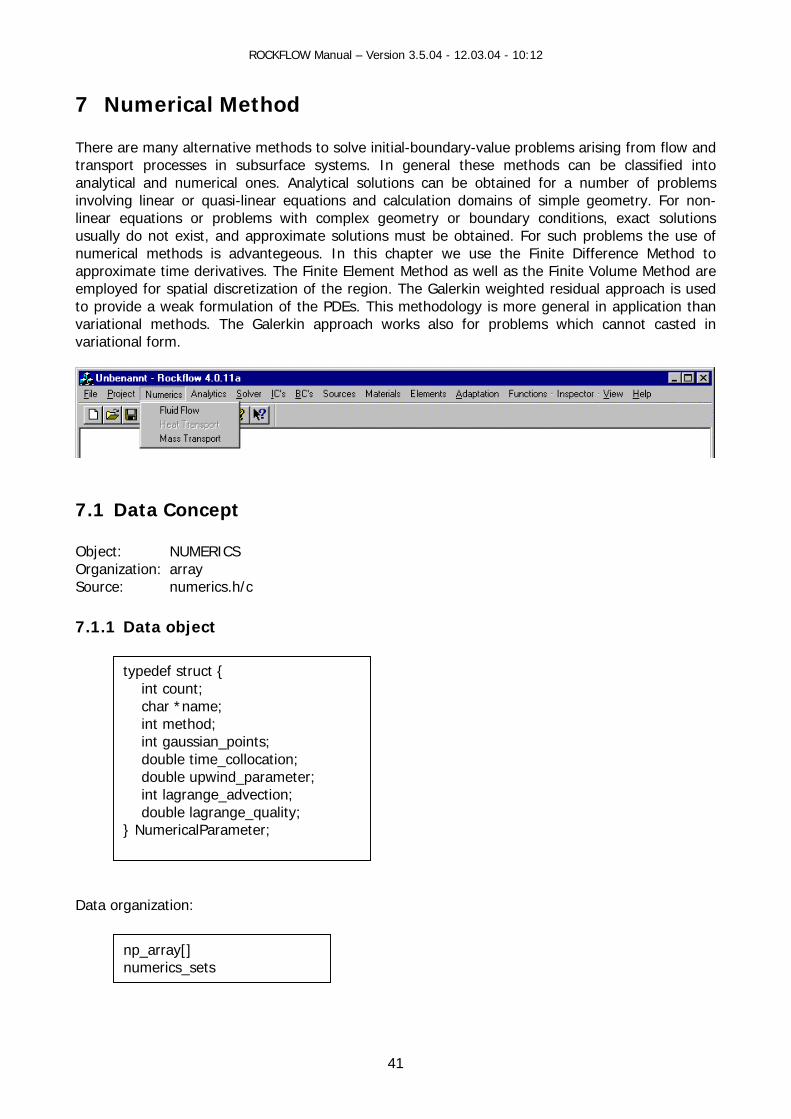
1.2 ROCKFLOW Source Files The figure below shows the mainframe menus and the connected sources files. Above, the GUI sources are given, and below, the FEM sources are printed.
7

ROCKFLOW Manual – Version 3.5.04 - 12.03.04 - 10:12
2 Data Files
2.1 Data Formats ROCKFLOW processes several files to input and output data. For each computation the program needs the two input files - the RFD file and the RFI file. Two output files are generated during the computation - RFE and RFO files. The RFD file contains a number of keywords which control all necessary adjustments, for example time stepping scheme, material properties, as well as physical and numerical parameters. The output RFE file contains a protocol of the RFD file. For a first computation of the flow models the RFI file only contains the geometry of the problem. The transport models need some special data, for example the pressure field, which are to be calculated by a flow model. If a restart of a computation is necessary the RFI file must contain the data of the last computed time step. An input file for a restart can be produced by copying parts of the RFO output file which has the same structure as the RFI input file.
Table: RF files and file interfaces File Extension Use RFD Input file for chemico-physical data RFI Input file for node geometry and element topology RFE Protocol of RFD file RFO Results output file NXX Output file for time profiles (temporal breakthrough curves) PXX Output file for spatial profiles at fixed time point File interface MSH Internal data format of Dali and RF-HGM PLT Input file for Tecplot (export) SMH Feflow supermesh data (import)
Withhelp of the file menu, a new RF project can be created or an existing input files can be red. The RF project consists of the RFD and RFI data.
8
ROCKFLOW Manual – Version 3.5.04 - 12.03.04 - 10:12
The menus File New and File Open cover important functions: construction of all data either interactively by model dialog or by reading the data from RFD and RFI input files.
Table: Structure of creator functions
Subject File New File Open Tests Destroy lists and objects
If necessary Destroy lists and objects If necessary
Object-Lists CreateObjectLists() CreateObjectLists() Objects Model dialog ReadData(dateiname) Object configuration ConfigRFObjects()
ConfigRFFiles(dateiname) Document data DeleteContents() WriteRFtoDoc()
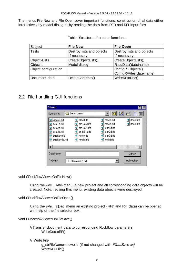
2.2 File handling GUI functions
void CR
a objects will be
oid CRockflowView::OnFileSave()
//Transfer document data to corresponding Rockflow parameters
g_strFileName=new.rfd (if not changed with File...Save as)
ockflowView::OnFileNew()
Using the File... New menu, a new project and all corresponding datenu, existing data objects were destroyed. created. Note, reusing this m
oid CRockflowView::OnFileOpen() v
Using the File... Open menu an existing project (RFD and RFI data) can be opened withhelp of the file selector box.
v
WriteDoctoRF(); // Write File
WriteRFDFile()
9

ROCKFLOW Manual – Version 3.5.04 - 12.03.04 - 10:12
void CRockflowView::OnFileSaveAs()
existing project (RFD and RFI data) can be saved withhelp of the file selector box.
erter
F2T C RF output data (RFO files) to Tecplot format
Using the File...Save As menu an
2.3 Data Conv R EMSH ow supermesh data to RFI format 2RF Fefl Data r geometric data - see RF-HGM Manual converter fo
10
ROCKFLOW Manual – Version 3.5.04 - 12.03.04 - 10:12
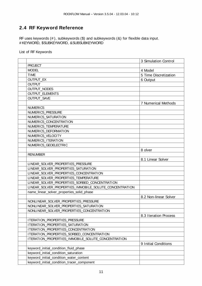
2.4 F Keyword Reference
F u subkeywords (&) for flexible data input. KEY
ist o
Simulation Control
R R ses keywords (#), subkeywords ($) and # WORD, $SUBKEYWORD, &SUBSUBKEYWORD L
f RF Keywords
3 PROJECT MODEL 4 Model TIME 5 Time Discretization OUTPUT_EX 6 Output OUTPUT OUTPUT_NODES OUTPUT_ELEMENTS OUTPUT_SAVE 7 Numerical Methods NUMERICS NUMERICS_PRESSURE NUMERICS_SATURATION NUMERICS_CONCENTRATION NUMERICS_TEMPERATURE NUMERICS_DEFORMATION NUMERICS_VELOCITY NUMERICS_ITERATION NUMERICS_GEOELECTRIC 8 olver RENUMBER 8.1 Linear Solver LINEAR_SOLVER_PROPERTIES_PRESSURE LINEAR_SOLVER_PROPERTIES_SATURATION LINEAR_SOLVER_PROPERTIES_CONCENTRATION LINEAR_SOLVER_PROPERTIES_TEMPERATURE LINEAR_SOLVER_PROPERTIES_SORBED_CONCENTRATION LINEAR_SOLVER_PROPERTIES_IMMOBILE_SOLUTE_CONCENTRATION name_linear_solver_properties_solid_phase 8.2 Non-linear Solver NONLINEAR_SOLVER_PROPERTIES_PRESSURE NONLINEAR_SOLVER_PROPERTIES_SATURATION NONLINEAR_SOLVER_PROPERTIES_CONCENTRATION 8.3 Iteration Process ITERATION_PROPERTIES_PRESSURE ITERATION_PROPERTIES_SATURATION ITERATION_PROPERTIES_CONCENTRATION ITERATION_PROPERTIES_SORBED_CONCENTRATION ITERATION_PROPERTIES_IMMOBILE_SOLUTE_CONCENTRATION 9 Initial Conditions keyword_initial_condition_fluid_phase keyword_initial_condition_saturation keyword_initial_condition_water_content keyword_initial_condition_tracer_component
11

ROCKFLOW Manual – Version 3.5.04 - 12.03.04 - 10:12
keyword_initial_condition_temperature 10 Dirichlet Boundary
Conditions keyword_boundary_condition_fluid_phase keyword_boundary_condition_saturation ke oyw rd_boundary_condition_conditional_saturation ke oyw rd_boundary_condition_wa er t _content ke oyw rd_boundary_condition_tracer_component ke o yw rd_boundary_condition_conditional_tracer_component ke o yw rd_boundary_condition_temperature keyword_boundary_condition_displacement_x keyword_boundary_condition_displacement_y keyword_boundary_condition_free_outflow keyword_boundary_condition_voltage_dc 11 Source/Sink Terms name_source_mass_fluid_phase name_source_volume_fluid_phase name_source_mass_tracer_component name_source_heat_phase keyword_boundary_condition_sorbed_component name_source_electric_current_dc name_sink_mass_fluid_mixture name_sink_volume_fluid_mixture LOAD_SOLID_PHASE_X LOAD_SOLID_PHASE_Y 12 Materials REFERENCE_CONDITIONS FLUID_PROPERTIES SOIL_PROPERTIES TRACER_PROPERTIES SOLID_PROPERTIES 13 Adaptation ADAPTATION ADAPTATION_PRESSURE ADAPTATION_TEMPERATURE ADAPTATION_COMPONENT ADAPTATION_SATURATION ADAPTATION_SORBED_COMPONENT ADAPTATION_SOLUTE_COMPONENT APRIORI_REFINE_ELEMENT Functions CURVES 14 Grafics BCURVE, GRAF, MESH2D, MESH3D, GRAF_EXTD Miscellaneous FRACTURE_APERTURE_DISTRIBUTION
12

ROCKFLOW Manual – Version 3.5.04 - 12.03.04 - 10:12
3 Simulation
• Selection of the physico-chemical model (4 Model) epping (5 Time Discretization)
(6 Data Output) • Runnig the simulator • Settings for on-line output to display (15 Graphics)
This pull-down menu deals with data to control the simulation:
• Contol of time st• Output of data
p e or a
m_bNonlinearTransport
m_bMassTransport
m_bMultiphaseFlow waterFlow
low m_bHeatTransportbyMultiphaseFlow m_bMassTransportbyGroundwaterFlow
m_bMassTransportbyGasFlow m_bMassTransportbyMultiphaseFlow
De ending on the selected physico-chemical model, a number of flags is used to activatde ctivate the corresponding mainframe pull-down menus:
m_bNonlinearFlow m_bFluidFlow m_bHeatTransport m_bGroundwaterFlow m_bGasFlow m_bHeatTransportbyGround m_bHeatTransportbyGasF
13

ROCKFLOW Manual – Version 3.5.04 - 12.03.04 - 10:12
4 Model
a general point of view according to the question, which program part drives and controls of that view.
Concept
There is the others. The below figure gives an idea
4.1 Data
In the center of that figure appears the model itself. At first it processes the model dependent data given by input files. The model independent data is stored in globally accessible data structures. rom the point of view software engineering the model equates with a two dimensional and
rinking matrix, which holds specific information for every node of the . the coordinates in all three spatial directions x, y and z.
e figu iving and which data structures it uses: • For the computation of different time steps, the time discretization the time loop is activated. • The adaption loop is activated, if the parts of the grid domain needs to be refined adaptively. • The iteration loop resolves non-linearities within the governing model equations. • The system of non-linear partial differential equations is described above. It is also known as
element loop. • The integration loop finally calculates the element matrices at the Gaussian points. • For the entire calculation steps the model needs information about geometry, topology and
different physical and chemical properties. So, it uses nodes, elements, initial and boundary conditions and material properties. Node, element and output data are managed by the model.
he MODEL consists of control, node and element data.
Fdynamically growing and shdiscretization of the area of interest, e.g The abov re also shows the entire parts the model is dr
• T
14

ROCKFLOW Manual – Version 3.5.04 - 12.03.04 - 10:12
4.1.1
Const ObjectConstr
Simulation Control Data Object: SIMULATION Source:Data:
models.h/c
FctProFctMod CallingReadD
DocumConstrReadDWriteR CallingOnFile
char *project_title = NULL; int modex; int model; int flow_model; int g_iDensityDependentFlow; int simulation; int multiphaseflow; int flow, tran, adaptiv; int transport_model_type; int chemical_model; long number_of_groups; long number_of_phases; long number_of_components; int fluid_phase; int saturation_on_phase; int transport_in_phase;
ruction
s uction from RFD file Construction Destruction ject() el()
CreateModelData() DestroyModelData()
functions Calling functions Calling functions ata() CreateAllData()
CRockflowView::OnFileNew()DestroyAllData() DestroyRFObjects() DestroyRFDObjects()
ent uction from RFD file Construction Destruction ata() + F2Doc_Simulation()
CreateModelData() + (Instance of CRockflowDoc)
DestroyModelData() + CRockflowDoc::DeleteContents()
functions Calling functions Calling functions
DestroyAllData() DestroyRFObjects() DestroyRFDObjects()
Open() CreateAllData() CRockflowView::OnFileNew()
CRockflowView::OnFileNew()
15

ROCKFLOW Manual – Version 3.5.04 - 12.03.04 - 10:12
4.1.2 Model Node Data The nodal values of the unknown functions are stored in the NODE objects. The model controls
nz_nval).
bject: NODE
nodes.h/c Data: Node data are attached to the NODE object.
void Crk->nva
oid DeleteNode ( long number ) ((Knoten *) nodelist->elements[number])->nval = (double *)Free(((Knoten *) nodelist->elements[number])->nval); ((Knoten *) nodelist->elements[number])->nval_intern = DestroyInternNodeData(((Knoten *) nodelist->elements[number])->nval_intern);
void DestroyNodeList (void)
the number of unknown functions (a OSource: mod_xxxx.h/c
int anz_nval; /* Number of node data */ void *nval /* Node data */ NvalInfo *nval_data = NULL; /* Node data information */
ess1, dummy; ,conc0,conc1;
int ref_rb_flow,ref_rb_tran;
int press0, print source
int satu; int dtidx;
Construction Knoten *NewNode()
k->nval_intern = InitInternNodeData() ble)); k->nval = (double *)Malloc(anz_nval*sizeof(dou
eateModelNodeData ( long number ) l = (double *)Malloc(anz_nval*sizeof(double));
v
16
ROCKFLOW Manual – Version 3.5.04 - 12.03.04 - 10:12
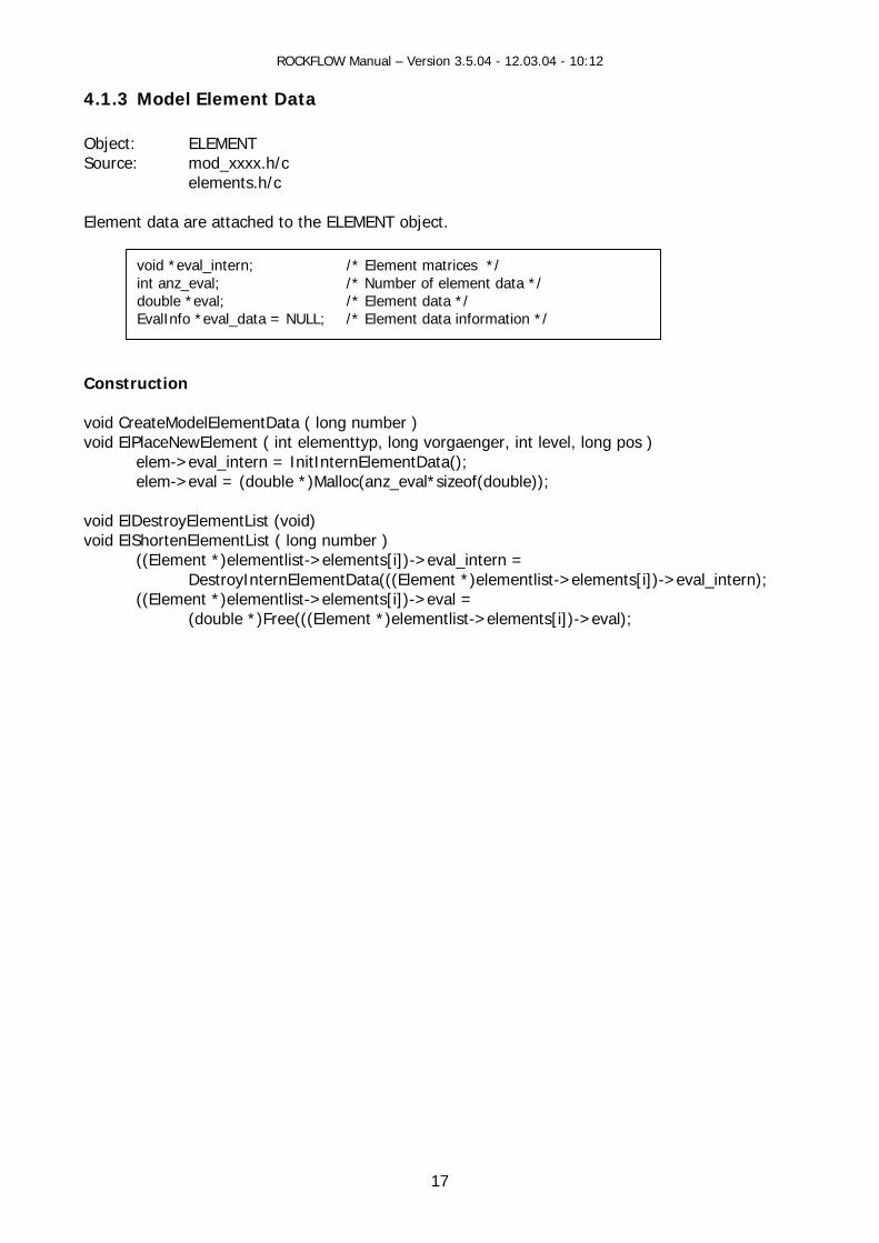
4.1.3 Model Element Data
Source: mod_xxxx.h/c elements.h/c Element data are attached to the ELEMENT object.
onstr
ata ( long number ) void ElP ger, int level, long pos )
elem->eval = (double *)Malloc(anz_eval*sizeof(double)); void ElDestroyElementList (void) void ElShortenElementList ( long number )
((Element *)elementlist->elements[i])->eval_intern = DestroyInternElementData(((Element *)elementlist->elements[i])->eval_intern);
((Element *)elementlist->elements[i])->eval = (double *)Free(((Element *)elementlist->elements[i])->eval);
Object: ELEMENT
void *eval_intern; /* Element matrices */ val; /* Number of element data */ val; /* Element data */
EvalInfo *eval_data = NULL; /* Element data information */
int anz_edouble *e
C uction void CreateModelElementD
laceNewElement ( int elementtyp, long vorgaenelem->eval_intern = InitInternElementData();
17

ROCKFLOW Manual – Version 3.5.04 - 12.03.04 - 10:12
4.1.4 Model Output Data
ource: filesx.h/c
onstruction
void SelectData ( int lsr ) datafield tafield_n,danz_n*sizeof(DatenFeld)); datafield_e = (DatenFeld *) Realloc(datafield_e,danz_e*sizeof(DatenFeld));
troyFileData ( void )
datafield_n = (DatenFeld *)Free(datafield_n);
S
int danz_n; /* Number of node output data */
e; /* Node output data array */
DatenFeld *datafield_n; /* Node output data array */ int danz_e; /* Number of node output data */ DatenFeld *datafield_
C
_n = (DatenFeld *) Realloc(da
void Desvoid SelectData ( int lsr )
datafield_e = (DatenFeld *)Free(datafield_e);
18
ROCKFLOW Manual – Version 3.5.04 - 12.03.04 - 10:12
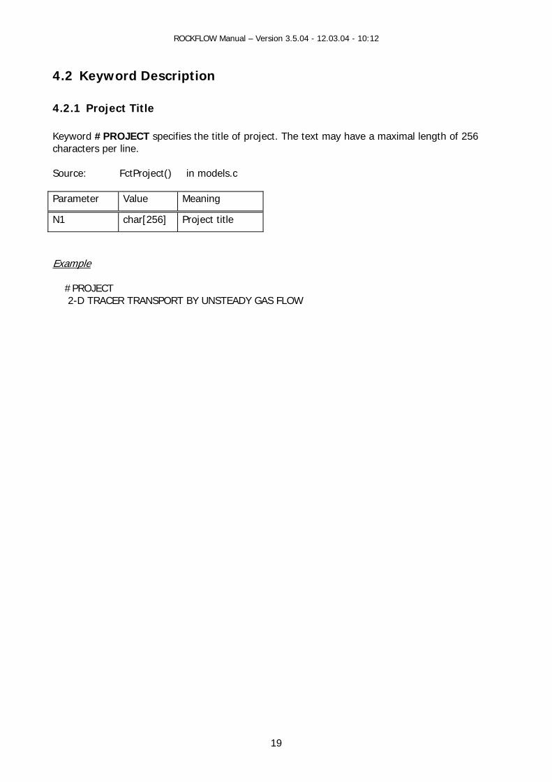
4.2 Keyword Description
eyword #PROJECT specifies the title of project. The text may have a maximal length of 256 characters per line. S Fc Parameter M
4.2.1 Project Title K
ource: tProject() in models.c
Value eaning
N1 Pchar[256] roject title
Example #PROJE 2-D TR ANS RT
CT ACER TR PO BY UNSTEADY GAS FLOW
19

ROCKFLOW Manual – Version 3.5.04 - 12.03.04 - 10:12
4.2.2 Model Sour FctModel() The keyword ODEL contro of the program and specifies the physico-chemical model. Defaults are
FEM Value
Dialog Value
Meaning
ce: in models.c
#M ls the execution mode printed bold.
Para-meter N1 modex
-2
0
Simulation control (modex): RFD input file will be tested. Result in RFE fil
-1 1
1 2
e RFD and RFI input files will be tested. Result in RFE file Execution of the FEM-Simulation
N2 Mo ( l)Model 0 0 Groundwate 2 1 G w p le fluids)
6 2 Multiphase Flow10093 3 Heat transport by groundwater flow 10097 4 Reactive transport b groundwater flow 10299
10010
5
8
dels mode : r flow
as flo (com ressib
yReactive transport by gas flow
or tracer transport by multiphase flow; geoelectric field calculations
omponent transport by ground water flow Consolidation processes
10699
6 Heat and tracer transport by single phase (multicontinua) flow
10095 7 Multic
N3 Flow model (flow_model): 0
1 0 1
Darcy law (linear flow behavior) Forchheimer law (non-linear flow behavior)
N4
0 1
0 1
Density-dependent flow (g_iDensityDependentFlow): Constant density flow (flow of homogeneous liquid) Density dependent flow (flow of heterogeneous liquid)
N5
0 1 2
0 1 2
Reactive transport model (chemical_model): No sorption reaction Equilibrium sorption reactions Nonequilibrium sorption reactions
N6 -1 0 1
0 1
Transport in multiphase flow (transport_in_phase): In all phases In non-wetting phase (e.g. air or oil) In wetting phase (water)
N7 0 1 2 3
Optimization of coupled transient problems (simulation): - flow only - unsteady flow and transport - steady flow and transport - transport only
N8 1 Number of material (soil/rock) groups (number_of_groups)
N9 1 Number of fluid phases (number_of_phases)
N10 1 Number of chemical components (number_of_components)
N11 0 1
Grid adaptation flag (adaptive_mesh_refinement_flag): disable adaptation enable adaptation
20
ROCKFLOW Manual – Version 3.5.04 - 12.03.04 - 10:12
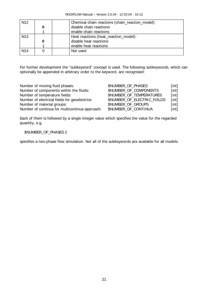
N12 0 1
Chemical chain reactions (chain_reaction_model): disable chain reactions enable chain reactions
N13 0 1
Heat reactions (heat_reaction_model): disable heat reactions enable heat reactions
N14 0 Not used
For further development the “subkeyword” concept is used. The following subkeywords, which can optionally be appended in arbitrary order to the keyword, are recognised: Number of moving fluid phases: $NUMBER_OF_PHASES [int] Number of components within the fluids: $NUMBER_OF_COMPONENTS [int] Number of temperature fields: $NUMBER_OF_TEMPERATURES [int] Number of electrical fields for geoelectrics: $NUMBER_OF_ELECTRIC_FIELDS [int] Number of material groups: $NUMBER_OF_GROUPS [int] Number of continua for multicontinua approach: $NUMBER_OF_CONTINUA [int] Each of them is followed by a single integer value which specifies the value for the regarded quantity, e.g. $NUMBER_OF_PHASES 2 specifies a two-phase flow simulation. Not all of the subkeywords are available for all models.
21

ROCKFLOW Manual – Version 3.5.04 - 12.03.04 - 10:12 ROCKFLOW Manual – Version 3.5.04 - 12.03.04 - 10:12
22
22

ROCKFLOW Manual – Version 3.5.04 - 12.03.04 - 10:12
4.3 Ressource Description
sh_simu.h/ *.ccp CSimulation
IDD_PROJECT_MODEL
model.h/c Source file Class Base class CDialog Ressource-ID Control elements Member variables Member functions RF-variables IDC_EDIT_PROJECT_NAME m_strProjectTitle project_title IDC_RADIO_SIMU1 m_iSimulationControl modex IDC_RADIO_SIMU3 IDC_MODEL_LIST m_ModelList
m_iModelTypeSel OnSelchangeModelList() model
IDC_CHECK_FORCH m_bNonlinearFlow flow_model IDC_CHECK_CONVECT m_bDensityDependentFlow g_iDensityDependentFlow IDC_LIST_TRANSPORT_PHASE m_TransportPhase
m_iTransportPhaseSel transport_in_phase
IDC_EDIT_PHASES m_iPhaseNumber number_of_phases IDC_EDIT_COMPONENTS m_iComponentNumber number_of_components IDC_EDIT_MATERIAL_GROUPS m_iGroupNumber number_of_groups IDC_RADIO_SIMU_O1 m_iSimulationOptimization simulation IDC_CHECK_ADAPTATION m_bGridAdaptation adaptive_mesh_refineme
nt_flag IDC_RADIO_MOD_RTM_1 m_iReactionModel chemical_model IDC_CHECK_MOD_RTM_1 m_bChainReactionModel chain_reaction_model ID_CANCEL ID_OK
23
ROCKFLOW Manual – Version 3.5.04 - 12.03.04 - 10:12
24
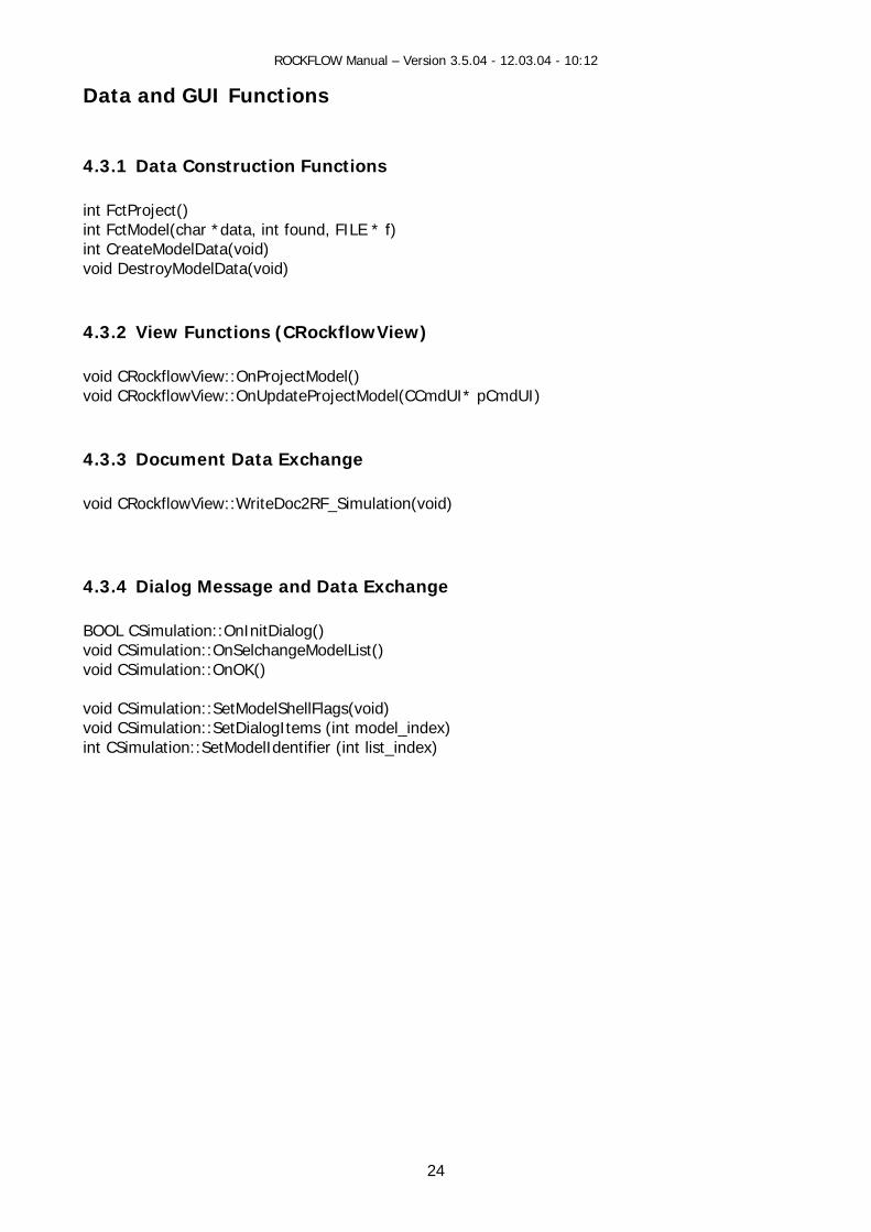
Data and GUI Functions
4.3 Functions intint E * f) int ) void DestroyModelData(void)
4.3.2 View Functions (CRockflowView) void CRockflowView::OnProjectModel() void CRockflowView::OnUpdateProjectModel(CCmdUI* pCmdUI)
4.3.3 Document Data Exchange void CRockflowView::WriteDoc2RF_Simulation(void)
4.3.4 Dialog Message and Data Exchange BOOL CSimulation::OnInitDialog() voi geModelList() voi void CSimulation::SetMvoi n::SetDi nt model_index) int etMo r (i
.1 Data Construction
FctProject() FctModel(char *data, int found, FIL CreateModelData(void
d CSimulation::OnSelchand CSimulation::OnOK()
odelShellFlags(void) d CSimulatio alogItems (iCSimulation::S delIdentifie nt list_index)

ROCKFLOW Manual – Version 3.5.04 - 12.03.04 - 10:12
Time Discretization
bject: TIME Organization: array of TimeSteps Source: rftime 5.1.1 Data Object
5
5.1 Data Concept O
5.1.2 SourceData TConstrDestru
int dt_steu; /* Flag fuer Zeitschrittsteuerung */ double startzeit, endezeit; /* Beginn und Ende der Rechnung */ long anz_zeitschritte; /* Gesamtzahl der zu rechnenden Zeitschritte */ long anz_dt_bloecke; /* Anzahl der eingelesenen TimeStep-Bloecke */ long aktueller_zeitschritt; /* Nummer des aktuellen Zeitschritts */ double aktuelle_zeit; /* zugehoeriger Zeitpunkt */ double dt; /* Zeitschritt */ float dt_steu_param; typedef struct { long anzdt; double dt; } TimeSteps
25
ction
Dialog
Constru
RFD File ype Object Object Document uction FctTime() CreateTimeData() WriteDoctoRF_TimeDiscretization() ction DestroyTimeData() DeleteContents()
ROCKFLOW Manual – Version 3.5.04 - 12.03.04 - 10:12
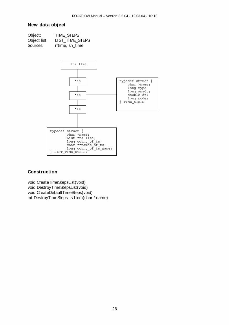
New data object O
26
sh_time
Construction void CreateTimeStepsList(void) void DestroyTimeStepsList(void) void CreateDefaultTimeSteps(void) int DestroyTimeStepsListItem(char *name)
bject: TIME_STEPS Object list: LIST_TIME_STEPS Sources: rftime,
*ts
*ts
*ts
*ts list
typede
f struct { char *name;
List *ts_ long count_of_ts; char **names_of_ts;
long count _name; LIST_TIME_STEPS;
list;
_of_ts }
typedef struct { char *name;
uble dt;
long type long anzdt; do long mode; } TIME_STEPS

ROCKFLOW Manual – Version 3.5.04 - 12.03.04 - 10:12
27
U #TIM ng sc eme can be specified.
lue tion
Meaning
5.2 Keyword Description
sing the keyword E , the time steppi h
Parameter Variables
VaTest func
N1 m_dFinalSimulation endezeit
user def. 0. c
TFEndezeit
Fin [seco putation will be stopped
Prescribed time stepping
al simulation time in ] (the m then)
N2 umber
Maximum number of time steps e cribed time stepping m_ImaximumTimeStepN
anz_zeitschritte
user def.0 Pr
TFAnz_zeitschrittes
N3 m_iTimeStepControl dt_steu g_nSelectedTimeStepModel
0 >0 be
TFDt_steu
Strictly prescribed time stepping scheme will sed
Tim will by the
ue stepping scheme be controled model
General: Time step sets timesteps[i].anzdt (0<i<anz_dt_bloecke) N4 m_ITimeStepNumber m_TimeStepList
TFAnzdt
Nuuser def. mber of time steps
N5 m_dTimeS
steps[i]tepLength .dt
user def. TFDt
Time step length in [sec]
time
...
ROCKFLOW Manual – Version 3.5.04 - 12.03.04 - 10:12
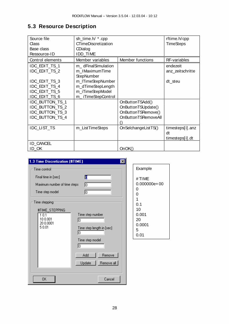
5.3 Resource Description
28
Class e.h/ *.cpp
CTimeDiscretization
rftime.h/cpp TimeSteps
Source file sh_tim
Base class CDialog Ressource-ID IDD_TIME Control elements Member variables Member functions RF-variables IDC_EDIT_TS_1 m_ dFinalSimulation endezeit IDC_EDIT_TS_2 m_IMaximumTime anz_zeitschritte
StepNumber IDC_EDIT_TS_3 m_lTimeStepNumber dt_steu IDC_EDIT_TS_4 m_dTimeStepLength IDC_EDIT_TS_5 m_iTimeStepModel IDC_E l DIT_TS_6 m_ iTimeStepControIDC_BUTTON_TS_1 OnButtonTSAdd() IDC_BUTTON_TS_2 OnButtonTSUpdate() IDC_BUTTON_TS_3 OnButtonTSRemove() IDC_BUTTON_TS_4 OnButtonTSRemoveAll
() IDC_LIST_TS m_ListTimeSteps OnSelchangeListTS() timesteps[i].anz
dt timesteps[i].dt
ID_CANCEL ID_OK
OnOK()
Example #TIME
0000e+00 0 0 1 0.1 10
0.01
0.00
0.001 20 0.00015
ROCKFLOW Manual – Version 3.5.04 - 12.03.04 - 10:12
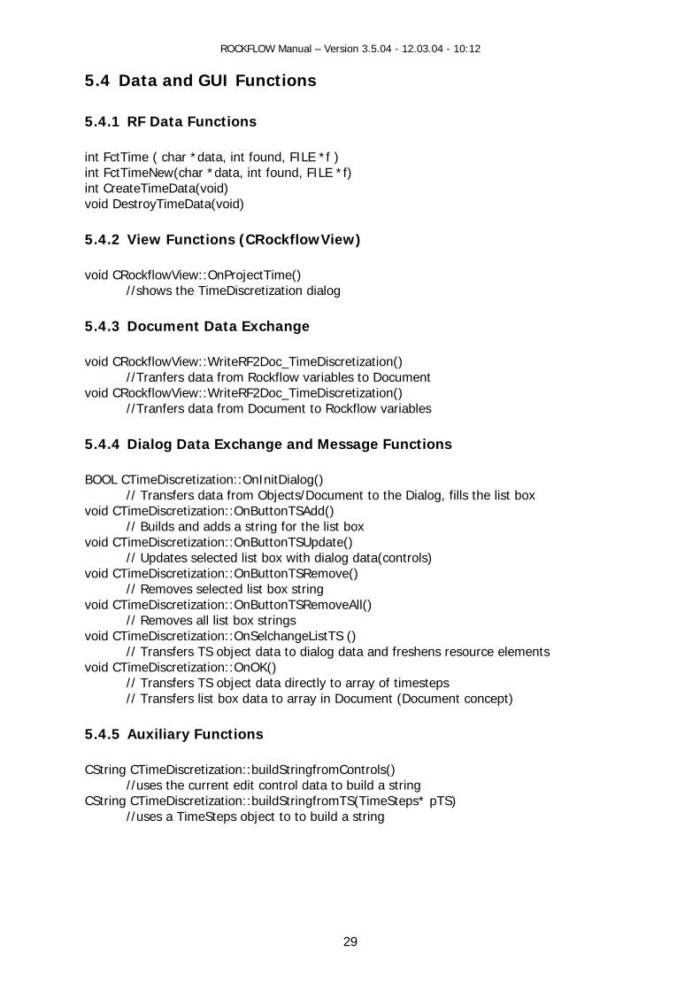
5.4 Data and GUI
Functions
5.4.1 RF Data Functions
int FctTime ( char *data, int found, FILE *f ) data, int found, FILE *f)
OnProjectTime() imeDiscretization dialog
5.4.3 Document Data Exchange void CRockflowView::WriteRF2Doc_TimeDiscretization() //Tranfers data from Rockflow variables to Document void CRockflowView::WriteRF2Doc_TimeDiscretization() //Tranfers data from Document to Rockflow variables
5.4.4 Dialog Data Exchange and Message Functions BOOL CTimeDiscretization::OnInitDialog()
// Transfers data from Objects/Document to the Dialog, fills the list box void CTimeDiscretization::OnButtonTSAdd()
dds a string for the list box void CTimeDiscretization::OnButtonTSUpdate()
// Up cted list box with dialog data(conmeD ion::OnButtonTSRemove()
e boxD n
Re gvoid CTimeDiscretization::OnSelchangeListTS ()
// Transfers TS object data to dialog data and freshens resource elements void CTimeDiscretization::OnOK()
// Transfers TS object data directly to array of timesteps // Transfers list box data to array in Document (Document concept)
5.4.5 Auxiliary Functions CString CTimeDiscretization::buildStringfromControls() //uses the current edit control data to build a string CString CTimeDiscretization::buildStringfromTS(TimeSteps* pTS) //uses a TimeSteps object to to build a string
int FctTimeNew(char *int CreateTimeData(void) void DestroyTimeData(void)
5.4.2 View Functions (CRockflowView)
void CRockflowView:: //shows the T
// Builds and a
dates selet
trols) void CTi
/iscretizamoves selected list / R
void CTime string
iscretization::OnButtomoves all list box strin
TSRemoveAll() // s
29
ROCKFLOW Manual – Version 3.5.04 - 12.03.04 - 10:12
6 Data Output
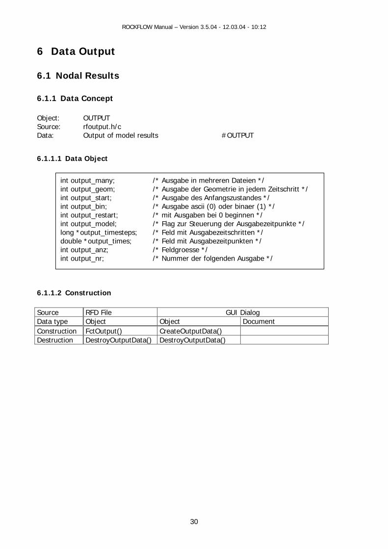
6.1.1 Data Concept O OUTPUT S rfoutput.hData: Output of odel
6.1.1.1 Data Object
6.1.1.2 Construction Source RFD File GUI Dialog
6.1 Nodal Results
bject:ource: /c
m results #OUTPUT
Data type Object Object Document Construction FctOutput() CreateOutputData() Destruction DestroyOutputData() DestroyOutputData()
int output_many int output_geom itschritt */
tput_start; des */ int output_bin; */ int output_restar eginnen */ int output_mode itpunkte */ long *output_timesteps;double *output_times; /
t_anz; t_nr; /* Nummer der folgenden Ausgabe */
; ;
/* Ausgabe in mehreren Dateien */ /* Ausgabe der Geometrie in jedem Ze
int ou /* Ausgabe des Anfangszustanr binaer (1) /* Ausgabe ascii (0) ode
/* mit Ausgaben bei 0 bt; l; /* Flag zur Steuerung der Ausgabeze
*/ /* Feld mit Ausgabezeitschritten /* Feld mit Ausgabezeitpunkten *
int outputpu
/* Feldgroesse */ int ou
30
ROCKFLOW Manual – Version 3.5.04 - 12.03.04 - 10:12
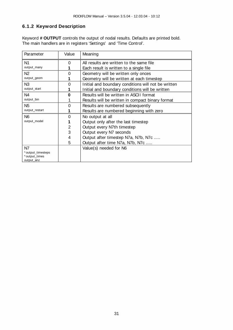
6.1.2 Keyword Description Keyword #OUTPUT controls the output of nodal results. Defaults are printed bold. he main handlers are in registers ‘Settings’ and ‘Time Control’.
eter Va
T
Param lue Meaning
N1 output_many
0 All results are w1 Each result
ritten to the same file is written to a single file
N2 output_geom
ll be wriry will be wri each timestep
0 1 Geomet
Geometry wi tten only ten at
onces t
N3 output_start
0 Initial and bo and boundary conditions 1 Initial
undary not be wrwill be written
conditions will itten
N4 output_bin
0 Results wi1
ll be written in ASCII format Results will be written in compact binary format
N5 ut_restart
1
Results are numbere equently Results are numbered beginning with zero
0 d subsoutp
N6 output_model
0 1 2 3 4 5
No output at all Output only after the last timestep Output every N7th timestep Output every N7 seconds Output after timestep N7a, N7b, N7c ..... Output after time N7a, N7b, N7c .....
N7 *output_timesteps *output_times output_anz
Value(s) needed for N6
31

ROCKFLOW Manual – Version 3.5.04 - 12.03.04 - 10:12
6.1.3 Resource Description
O s
essource-ID D_OUTPUT_FILES
rftime.h/c
utput File
Source file Class Base class R
sh_out.h/ccp COutputFiles CPropertyPage ID
Control elements Member variables Member functions F-variables R OnInit IDC_RADIO_OUT_F1 utput_many m_iOutputFiles oIDC_RADIO_OUT_F3 m_iOutputGeometry output_geom IDC_RADIO_OUT_F5 m_iOutputIC output_start IDC_RADIO_OUT_F7 m_iOutputFormat output_bin ID_CANCEL ID_OK OnOK
32

ROCKFLOW Manual – Version 3.5.04 - 12.03.04 - 10:12
Output Time Control Source file Class
sh_out.h/ccp COutp
Base class Ressource-ID IDD_OUTPUT_TIME
utTime CPropertyPage
rftime.h/c
Control elements Member variables Member functions RF-variables OnInit IDC_EDIT_OUT_T1 m_lOutputTimeStepList IDC_EDIT_OUT_T2 m_dOutputTimeList IDC_EDIT_OUT_T3 m_IOutputTimeStepInterval IDC_EDIT_OUT_T4 m_dOutputTimeInterval IDC_RADIO_OUT_T1 m_iOutputTimeType=0 OnRadioOutT1 output_model=4 IDC_RADIO_OUT_T2 m_iOutputTimeType=1 output_model=5 IDC_RADIO_OUT_T3 m_iOutputTimeType=2 output_model=2 IDC_RADIO_OUT_T4 m_iOutputTimeType=3 output_model=3 IDC_RADIO_OUT_T5 m_iOutputTimeType=4 output_model=1 IDC_RADIO_OUT_T6 m_iOutputTimeType=5 output_model=0 IDC_BUTTON_OUT_T1 OnButtonAddList1 IDC_BUTTON_OUT_T2 OnButtonUpdateList1 IDC_BUTTON_OUT_T3 OnButtonRemoveList1 IDC_BUTTON_OUT_T4 OnButtonRemoveAllList1 IDC_BUTTON_OUT_T5 OnButtonAddList2 IDC_BUTTON_OUT_T6 OnButtonUpdateList2 IDC_BUTTON_OUT_T7 OnButtonRemoveList2 IDC_BUTTON_OUT_T8 OnButtonRemoveAllList2 IDC_LIST_OUT_T1 m_LBOutputTimeStepList OnSelchangeListOutT1 output_times IDC_LIST_OUT_T2 m_LBOutputTimeList OnSelchangeListOutT2 output_timesteps ID_CANCEL ID_OK OnOK
33
ROCKFLOW Manual – Version 3.5.04 - 12.03.04 - 10:12
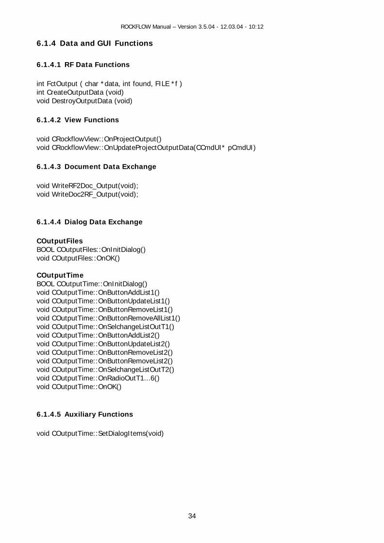
6.1.4 Data and GUI Functions
.1.4.1 RF Data Functions
, int found, FILE *f ) t CreateOutputData (void)
void)
2 View
void CRockflowView::OnProjectOutput() void CRockflowView::OnUpdateProjectOutputData(CCmdUI* pCmdUI)
.1.4.3 Document Data Exchange
eRF2void WriteDoc2RF_Output(void); 6.1.4.4 Dialog Data Exchange
OutputFiles itDialog()
oid COutputFiles::OnOK()
COu BOO e:void ::Ovoid COutputTime::O () void e::O ( oid COutputTime::OnButtonRemoveAllList1()
void COutputTime::OnSelchangeListOutT1() void COutputTime::OnButtonAddList2() void COutputTime::OnButtonUpdateList2() void COutputTime::OnButtonRemoveList2() void COutputTime::OnButtonRemoveList2() void COutputTime::OnSelchangeListOutT2() void COutputTime::OnRadioOutT1...6() void COutputTime::OnOK() 6.1.4.5 Auxiliary Functions void COutputTime::SetDialogItems(void)
6 int FctOutput ( char *datainvoid DestroyOutputData ( 6.1.4. Functions
6 void Writ Doc_Output(void);
CBOOL COutputFiles::OnInv
tputTimeL COutputTim COutputTime
:OnInitDialog() nButtonAddList1() nButtonUpdateList1
COutputTim nButtonRemoveList1 ) v
34

ROCKFLOW Manual – Version 3.5.04 - 12.03.04 - 10:12
6.2 Temporal Profiles
.2.1 Data Concept 6.2.1.1 Da ts Data: Temporal profiles a ne
6.2.1.
So
6
ta Objec
t defi d nodes #OUTPUT_NODES
Data:
DaCo
De
exte utput_nodes; oten-Durchbruchskurven */exte _node ; extern int out
rn int o /* Ausgabe von Knrn long *output _array /* Array der Ausgabe-Knoten */
put_node_anz; /* Arraygroesse */
Temporal profiles at defined elements #OUTPUT_ELEMENTS
int ments; abe von Element-Durchbruchskurven */lon utput_ elements _array; der Ausgabe-Elemente */ int
output_ ele /* Ausgg *o /* Arrayoutput_ elements _anz; /* Arraygroesse */
2 Construction
urce RFD File GUI Dialog ta type Object Object Document nstruction FctOutputNodes
FctOutputElements
struction DestroyOutputData
35

ROCKFLOW Manual – Version 3.5.04 - 12.03.04 - 10:12
6.2.2 Keyword Description
eyword #OUTPUT_NODES specifies nodes, for which temporal breakthrough curves will be w
arameter Meaning
K
ritten.
P Value
N1 output_nodes
>0
o output ode results ary f
Node results n in ASCII format Value corresp o output time step
0 <0
NN will be written in bin ormat
will be writteonds t
N2 ... *output_node_ar
odesum 100 nodes can be speray
Output na maximlong (
of cified)
K L MENTS specifies elements, reak hrough curves will b
Value Meaning
eyword #OUTPUT_E E for which temporal b te written.
Parameter
N1 output_elements
0 <0
No output Element resul r format
ement resul CIIe corresp ep
>0 Elts will be written in bina y ts will be written in AS format
Valu onds to output time st N2 ... *output_element_array
long
Output elements (a maximum of 100 nodes can be specified)
36

ROCKFLOW Manual – Version 3.5.04 - 12.03.04 - 10:12
6.2.3 Resource Description
sh_out.h/ccp
OUTPUT_PROFILE_TIME
rfoutput.h/c Source file Class COutputProfileTime Base class CPropertyPage Ressource-ID IDD_
Control elements Member variables Member functions RF-variables OnInitDialog OnOK IDC_EDIT_OUT_P1 m_lOutputNode output_node_array IDC_EDIT_OUT_P2 m_lOuputNodeTimeInterval output_nodes IDC_EDIT_OUT_P3 m_lOutputElement output_element_array IDC_EDIT_OUT_P4 m_lOutputElementTimeInterval output_elements IDC_BUTTON_OUT_P1 OnButtonAddList1 IDC_BUTTON_OUT_P2 OnButtonUpdateList1 IDC_BUTTON_OUT_P3 OnButtonRemoveList1 IDC_BUTTON_OUT_P4 OnButtonRemoveAllList1 IDC_BUTTON_OUT_P5 OnButtonAddList2 IDC_BUTTON_OUT_P6 OnButtonUpdateList2 IDC_BUTTON_OUT_P7 OnButtonRemoveList2 IDC_BUTTON_OUT_P8 OnButtonRemoveAllList2 IDC_LIST_OUT_P1 m_LBOutputNodes OnSelchangeListOutP1 output_node_array IDC_LIST_OUT_P2 m_LBOutputElements OnSelchangeListOutP2 output_element_array
37
ROCKFLOW Manual – Version 3.5.04 - 12.03.04 - 10:12
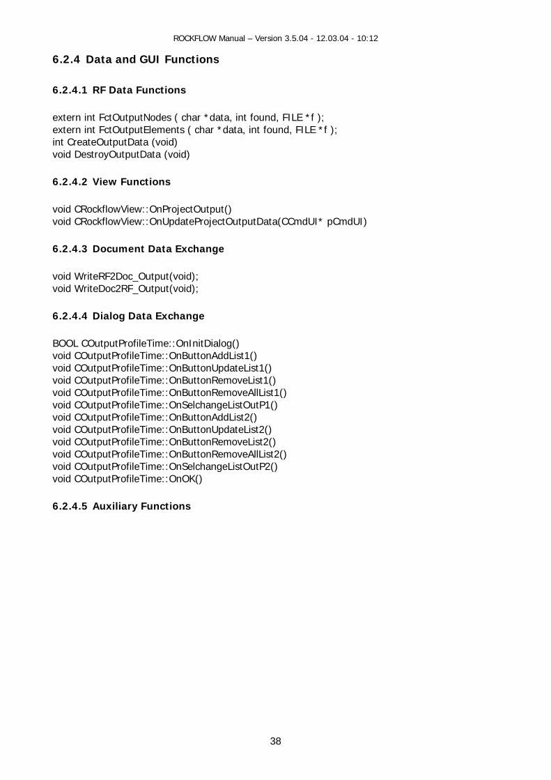
6.2.4 Data and GUI Functions
1 RF D
extern int FctOutputNodes ( char *data, int found, FILE *f ); extern int FctOutputElements ( char *data, int found, FILE *f ); int CreateOutputData (void) void DestroyOutputData (void) 6.2.4.2 View Functions void CRockflowView::OnProjectOutput() void CRockflowView::OnUpdateProjectOutputData(CCmdUI* pCmdUI) 6.2.4.3 Document Data Exchange void WriteRF2Doc_Output(void); void WriteDoc2RF_Output(void); 6.2.4.4 Dialog Data Exchange BOOL COutputProfileTime::OnInitDialog() void COutputProfileTime::OnButtonAddList1() void COutputProfileTime::OnButtonUpdateList1() void COutputProfileTime::OnButtonRemoveList1() void COutputProfileTime::OnButtonRemoveAllList1() oid COutputProfileTime::OnSelchangeListOutP1() oid COutputProfileTime::OnButtonAddList2()
eTime::OnButtonUpdateList2() fileTime::OnButtonRemoveList2()
oid COutputProfileTime::OnButtonRemoveAllList2() tputPro nSelchange
utPro :OnOK()
6.2.4.5 Auxilia
6.2.4. ata Functions
vvvoid COutputProfilvoid COutputProvvoid COu fileTime::O ListOutP2() void COutp fileTime:
ry Functions
38

ROCKFLOW Manual – Version 3.5.04 - 12.03.04 - 10:12
6.3 Output Object Data: New data object for data outpu # OUTPUT_BTC t
Construction Source RFD File GUI Dialog
Data type Object Object Document FctOutput FctOutputNodes FctOutputElements FctOutputSave
Construction
CreateOutputList FctOutputBTC
Destruction DestroyOutputData DestroyOutputList
typedef struct { char *name;
long type; long curve; int index; long mode; long level; long begin_node; long end_node; long step_nodes; long start_element; long end_element; long step_elements; long count_of_values; double *values; double *x; double *y; double *z; double radius; long count_of_points; long distribution_type; } OUTPUT;
39

ROCKFLOW Manual – Version 3.5.04 - 12.03.04 - 10:12
6.4 Backup Files Data: Backup files for model results #OUTPUT_SAVE
int output_save; /* Sicherheitskopien in wechselnde Dateien */ int output_save_file; /* Zeiger fuer Ausgabe-Datei*/
40
ROCKFLOW Manual – Version 3.5.04 - 12.03.04 - 10:12
7 Numerical Method
any a ve methods to solve oundary-value problems flow and es stems c n be classified into nu s or a
volving linear or quasi-linear equations and calculation domains of simple geometry. For non- solutions
uch problems the use of nce Method to
e F s the Finite Volume Method are mployed for spatial discretization of the region. The Galerkin weighted residual approach is used provide a weak formulation of the PDEs. This methodology is more general in application than
ds. The Galerkin approach works also for problems which cannot casted in
There are m lternati initial-b arising fromtransport proc ses in subsurface sy . In general these methods aanalytical and merical ones. Analytical olutions can be obtained f number of problems inlinear equations or problems with complex geometry or boundary conditions, exactusually do not exist, and approximate solutions must be obtained. For snumerical methods is advantegeous. In this chapter we use the Finite Differeapproximate time derivatives. Th inite Element Method as well aetovariational methovariational form.
7.1 Data Concept
bject: NUMERICS y
: numerics.h/c
7.1 Da
ata organization:
OOrganization: arra Source
.1 ta object
np_array[] numerics_sets
typedef stru { int count; char *name;
int gaussian_points; double time_collocation;
_parameter; int lagrange_advection;
ct
int method;
double upwind
double lagrange_quality; } NumericalParameter;
D
41

ROCKFLOW Manual – Version 3.5.04 - 12.03.04 - 10:12
7.1.2 Construction Source RFD File GUI Dialog Data type Object Object Document Construction FctNumericsMethods CreateDefaultNumericsObject Destru stroyAl ics estroyAllNumericsObject ction De lNumer Object D FctNum ods CreateD ltNumericsObject e DestroyAllNumericsObject
7.1.3 RF-FEM variables iables Value
ericsMeth Processes all data headed by keyword #NUMERICS Object identification by name
efau Creates a default NUMERIC object with nam Destroys all NUMERIC objects
Names
RF-Shell varname_numerics_fluid_phase PRESSURE name_n tura umerics_fluid_sa tion SATURATION name_n ature hase TEMPERATURE umerics_temper _pname_n rics_concentrat mpume ion_co onent CONCENTRATION
m_strNUMname
bject names can be defined by the user.
bject configuration:
el Model 0097
Model 0297
Model 0697
Model 0093
Model 0095
Model 0499
O O Unknown Model Model Modindex 0 2 6 SM GM MM SM/RTM GM/RTM MM/RTM SM/HTM SM/MTM DM
0 PRESSURE
1 SATU-RATION
CONCEN-TRATION
CONCEN-TRATION
SATU-RATION
TEMPE-RATURE
CONCEN-TRATION
CONCEN-TRATION
2 CONCEN-TRATION
ToDo - ConfigNumericObjects()
7.1.4 Data Access
hod(char *name); on(char *name, double theta);
Access to data is provided via object name. int GetNumericsMetvoid SetNumericalTimeCollocati
42

ROCKFLOW Manual – Version 3.5.04 - 12.03.04 - 10:12
7.2 Keyword Description
e keyword #NUMERICS specifies numerical parameters for the FEM solution of the correspon-g PDE. Defaults are printed bold.
Parameter Value Meaning
Thdin
N1 .method
0 1 2
Bubnov-Galerkin-Method (Standard FEM) Petrov- hod (Upwind FEM) Euler-Taylor-Galerkin-Method (ETG)
Galerkin-Met
N2 name Object identification .name
by name
N3 1-4 Number of Gaussian integration points .gaussian_points
N4 .time_collocation
[0-1] Time collocation factor
N5 .upwind_parameter
[0-1] Upwind parameter
N6 .lagrange_advection
0 1
Lagrangian scheme for advective terms disabled Lagrangian scheme enabled (Operator-Splitting)
N7 [0,.lagrange_quality
1] 0.95
Parameter of Lagrangian scheme for advection terms to control approximation accuracy
For model 10699 the #NUMERICS keywords are no longer valid. These must be replaced by the eywords:
NUMERICS_GEOELECTRIC N
CS_ITERATION
ach of these keywords can contain a number of optional subkeywords (labeled by a $ sign),
value, which specifies the numerical method for the
For transport calculations: Use Lagrangian scheme for advective transport in 2D-elements . Requires additional parameters.
n scheme for 2D-elements, omit everything else.
k #NUMERICS_PRESSURE #NUMERICS_SATURATION #NUMERICS_CONCENTRATION #NUMERICS_TEMPERATURE ##NUMERICS_DEFORMATIO#NUMERICS_VELOCITY #NUMERI Ewhich are explained in the following: $METHOD The keyword is followed by an integerregarded process: 0 No calculation 1 Finite element calculation 3
(fractures). Compute everything else by FEM4 For transport calculations: Use Lagrangia
Requires additional parameters. 5 For transport calculations only. Use Lagrangian scheme for 2D-elements. Requires additional
parameters. 7 For unsaturated flow (pressure and saturation): The Richards’ formulation is used to compute
pressure and saturation fields.
43

ROCKFLOW Manual – Version 3.5.04 - 12.03.04 - 10:12
8 For unsaturated flow (pressure and saturation): The Celia-Richards’ formulation is used to pute pressure and saturation fields. com
For transport calculations only. Finite element calculation with artificial diffusion in critical regions. Reads additionally two double values. The first parameter p1 specifies the
h marks an element as critical. If the parameter is negative, concentrations will be normalised with the span of all concentrations in the system before
e is –0.25, i.e. the front should smoothed it is less than four elements wide.). The second parameter p2 specifies the additional diffusion multiplier. The
iplier is computed from
9
concentration difference whic
comparison (recommended valu
1p1pminmax__c
2p−
diffusion mult , where c_max_min is the (normalised) concentration difference within the regarded element.
GAUSS_POINTS
The keyword is followed by f Gaussian points for
quantity
TRANSPORT_IN_PHASE
he keyword is followed by an integer value (-1 ... number_of_phases). It specifies the number of rded.
ATION
ITERATION_METHOD
he keyword is followed by an integer value (0 ... number_of_phases). It specifies which phase ressure shall be used as reference in multiphase flow calculations.
he keyword is followed by an integer value (-1 ... number_of_phases). It specifies the method to turations in multiphase flow:
-1 All phase saturations are modified, so that they sum up to unity (Not recommended).
11 Same as 9. $
an integer value. It specifies the number ointegration (1 ... 4). At the time given this parameter must be the same for all processes.
$NONLINEAR_COUPLING The keyword is followed by an integer value (0 or 1). It specifies whether the regardedshall be regarded within the loop for non-linear iterations.
$ Tthe fluid phase for which transport processes shall be regarded. For –1 all phases are rega $PLASTIC_DEFORM not yet ... $ not yet ... $REFERENCE_PRESSURE_METHOD Tp $CALC_OTHER_SATURATION_METHOD Tcalculate phase sa
44
ROCKFLOW Manual – Version 3.5.04 - 12.03.04 - 10:12
>=0 The saturation of this phase will be computed from the other phase saturations. It is recommended to use the index of the least moveable phase.
IRR_NODES_CORRECTION
owed by an integer value which specifies the upwinding scheme.
atrices:
g of Gaussian integration points (scaled) , additional parameter (double) for upwinding factor is required. Compare THORENZ (2001).
Upwinding of Gaussian integration points (unscaled) , additional parameter (double) for upwinding factor is required. Compare THORENZ (2001).
to advection matrices only, additional parameter (double) for
matric
1 Streamline upwinding, add
eyword is followed by a s whether masslumping shall be sed to reduce wiggles. This can be very useful for multiphase flow calculations or transport
onts. Compare THORENZ (2001).
h owed predictor shall be used le parameter p1 is required. For
ediction
llowed by an integer value which specifies a scheme to reduce the computed inear iterations.
itional double parameter p1 is required.
$ ... not yet ready for prime time ... $UPWINDING The keyword is foll For the pressure field m 1 Upwindin
2
For the concentration and temperature field matrices: 1 Streamline upwinding, additional parameter (double) for upwinding factor is required. 2 Streamline upwinding applied
upwinding factor is required. Compare THORENZ (2001).
es: For the saturation field
itional parameter (double) for upwinding factor is required. $MASS_LUMPING
n integer value (0 or 1)which specifieThe kucalculations with very steep fr $PREDICTOR T e keyword is foll by an integer value (0 or 1). Specifies that a linear to estimate values for the next timestep. An additional doubp1=1.0 full pr is used. $RELAXATION The keyword is focorrection in non-l 0 No relaxation 1 Fixed relaxation, add
45
ROCKFLOW Manual – Version 3.5.04 - 12.03.04 - 10:12
2 Dynamic relaxation on the basis of field oscillations, 4 additional double parameters are required (recommended: 1. 0.25 0.5 0.5). Experimental, not for common use.
3 Dynamic relaxation on the basis of single node oscillations, 2 additional double parameters are required (recommended: 1. 0.5). Experimental, not for common use.
$EXTRACT_VALUES_FROM_PDE
he keyword is only valid for the pressure field. It is followed by an integer value (0 or 1) which specifies
et
$TIMECOLLOCATION
es t time coential equa
subsubkeywords (labe
A (double) &UPWINDING (dou pecifies the time collocation for the upwinding scheme
nded value: 0.) (double)
e as $GLOBAL, for mass fluxes of compressible fluids 0.0
(double)
&OPEN_BOUNDAR ecifies the time collocation for free outflow boundary
$INTEGRATION_PO
is followed by an integer value, giving the method for integration:
dle value for integration t values for integration
the pressure kernel and in the velocity calculation, the following values are recognized:
&VISCOSITY
$MATRIX_REBUILD
Twhether the results of the last timestep are extracted from the system of linear equations while assembling it. For systems with very large vertical extend this procedure reduces “small differences of large numbers” accuracy problems. $TIMESTEPPING not y ...
Specifi he llocation. The time collocation value can be chosen globally for the regarded partial differ tion and differently for certain parts. These are distinguished by optional
led with &)
&GLOB L Specifies the main time collocation (recommended value: 0.6) ble) S
(recomme &SOURCE Specifies the time collocation for sinks and sources (recommended
value: samleads to better stability)
&COND_BC Specifies the time collocation for conditional boundary conditions (recommended value: 0.)
Y (double) Spconditions (recommended value: 0.)
INTS Specifies how certain variables (specified by a subsubkeyword) are to be treated during integration. The subsubkeyword &NAME 1 Use element mid &NAME 2 Use Gauss poin In &DENSITY &REL_PERM
46
ROCKFLOW Manual – Version 3.5.04 - 12.03.04 - 10:12
Specifies the circumstances under whicmatrices is a substantial computation
h the system matrices are rebuild. As setting up the system al effort, choosing a conditional rebuild can significantly
ecrease computation time, though the reduced accuracy must be considered. For further i se THOR ethod not available for multi lations. A llow the sa p1 w pec ier for t garded matrix (de on the FE-Kernel), “ ger ises the who to evaluate the matrix rebuild and p1 to p jus
The following methods are valid:
0 N
1 p1 Rebuild if the characte more than p1 (criterion:
dnformation u ENZ (2001). This m is continua calcu
ll entries fo me scheme:
&NAME method p2 .... pn
here “&NAME” s ifies the identif he re pends method” is an inte value that character n are additional ad tment parameters.
ever rebuild.
ristic value diverges
1pxx ref >− ).
p1 Rebuild if the normalised characteristic value diverges more than p1
(criterion:
2
1pxx/xx2 refref >+− ).
3 p1 p2 Rebuild if both criterion 1 (parameter p1) and criterion 2 (parameter p2) are
fulfilled.
11 p1 p2 The rebuild is triggered by a probability approach. Probability P is derived
from evaluating ( ) 2pref 1p/xxP −= .
12 p1 p2 The rebuild is triggered by a probability approach. Probability P is derived
from evaluating ( ) 2prefref 1p/xx/xx2P +−= .
13 p1 p2 p3 p4 Rebuild if both criterion 11 (parameters p1 and p2) and criterion 12
(parameters p3 and p4) are fulfilled.
For the pressure kernel the following &NAME entries are recognised, the characteristic value is given by the name of the entry: &ELEMENT_MOBILITY_CHANGE &ELEMENT_DENSITY_CHANGE &ELEMENT_SATURATION_CHANGE For the transport kernel the following &NAME entries are recognised, the characteristic value is given by the name of the entry: &ELEMENT_SATURATION_CHANGE &ELEMENT_VELOCITY_CHANGE
47
ROCKFLOW Manual – Version 3.5.04 - 12.03.04 - 10:12
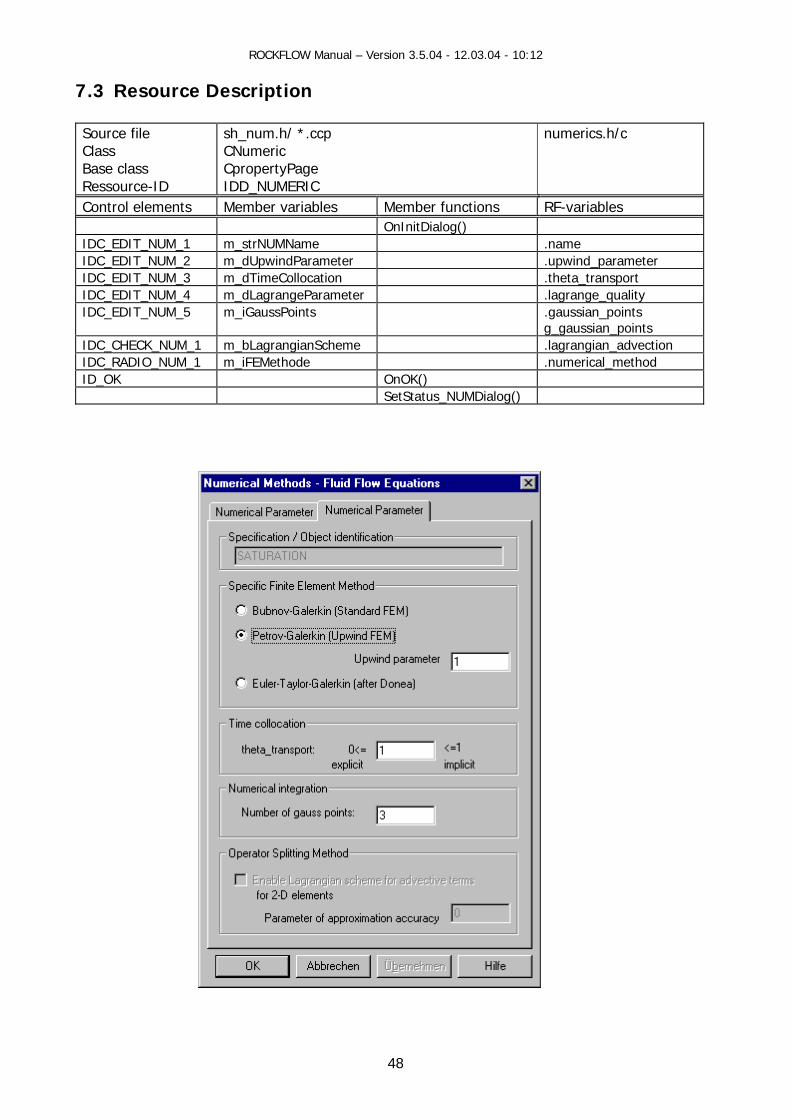
7.3 Resource Description
h/ *.ccp CNumeric
numerics.h/c Source file sh_num.Class Base class CpropertyPage
NUMERIC Ressource-ID IDD_Control elements Member variables Member functions RF-variables OnInitDialog() IDC_EDIT_NUM_1 m_strNUMName .name IDC_EDIT_NUM_2 m_dUpwindParameter .upwind_parameter IDC_EDIT_NUM_3 m_dTimeCollocation .theta_transport IDC_EDIT_NUM_4 m_dLagrangeParameter .lagrange_quality IDC_EDIT_NUM_5 m_iGaussPoints .gaussian_points
g_gaussian_points IDC_CHECK_NUM_1 m_bLagrangianScheme .lagrangian_advection IDC_RADIO_NUM_1 m_iFEMethode .numerical_method ID_OK OnOK() SetStatus_NUMDialog()
48

ROCKFLOW Manual – Version 3.5.04 - 12.03.04 - 10:12
7.4 GUI Fun
ctions
7.4.2 View Functions
ow() oid CRockflowView::OnNumericsHeatTransport() oid CRockflowView::OnNumericMassTransport()
.4.4 Dialog Functions
OOL CNumeric::OnInitDialog() oid CNumeric::OnOK()
.4.5 Auxiliary Function
oid CNumeric::SetStatus_NUMDialog(int m_iType)
7.4.1 RF Data Functions int FctNumericalMethodsNew(char *data, int found, FILE * f) NumericalParameter *CreateDefaultNumericsObject(char *name,int *numerics_sets) void DestroyAllNumericsObject(void)
void CRockflowView::OnNumericsFluidFlvv
7.4.3 Document Data Exchange oid CRockflowView::WriteRF2Doc_Numerics() v
void CRockflowView::WriteDoc2RF_Numerics()
7 Bv
7 v
49

ROCKFLOW Manual – Version 3.5.04 - 12.03.04 - 10:12
8 Solver Solving equation systems is a cruicial and most time-consuming point of every simulator. Several
ethods as direct and iterative equation solvers are available. Non-linear PDEs result in linearized. Non-linear problems of interest
ity-driven flow, reactive transport (non-ockflow provides linear as well as non-linear
mcorresponding non-linear equations, which have to beare: Forchheimer flow, gas flow, multiphase flow, denslinear equilibrium and non-equilibrium reactions). Requation solver (Habbar 1995).
8.1 Linear Equation Solver
8.1.1 Data Concept The parameters to control the solution process are contained in the below data structure (object).
r objects are organized in a list (object list). This concept is designed in particular for lving a large number of equation systems as for multiphase-multicomponental processes.
All solveso Object: LINEAR_SOLVER_PROPERTIES [LSP] Object list: LIST_LINEAR_SOLVER_PROPERTIES Source: rfsolver.h/c 8.1.1.1 Data Object
typedef struct { char *name; long type; long maxiter; double eps;
t;
;
long nom; long precond;
store; long long criterium; double theta; long repea double time; long kind; long level
} LINEAR_SOLVER_PROPERTIES;
List *lsp list
*lsp
*lsp
*lsp
typedef struct { char *name; List *lsp_list; long count_of_linear_solver_properties; char **names_of_linear_solver_properties; long count_of_linear_solver_properties_name; double *lsp_vector; } LIST LINEAR SOLVER PROPERTIES;
50
ROCKFLOW Manual – Version 3.5.04 - 12.03.04 - 10:12
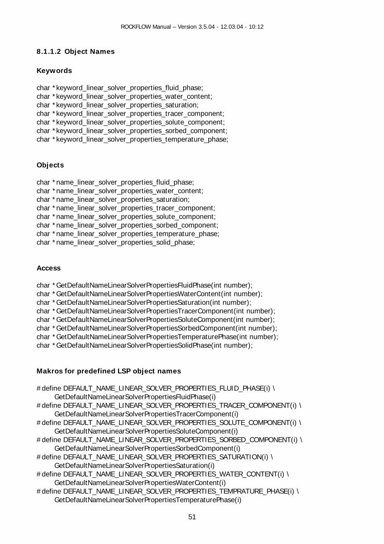
8.1.1.2 Object Names Keywords char *keyword_linear_solver_properties_fluid_phase; char *keyword_linear_solver_properties_water_content; char *keyword_linear_solver_properties_saturation; char *keyword_linear_solver_properties_tracer_component; char *keyword_linear_solver_properties_solute_component; char *keyword_linear_solver_properties_sorbed_component; char *keyword_linear_solver_properties_temperature_phase; Objects char *name_linear_solver_properties_fluid_phase; char *name_linear_solver_properties_water_content; char *name_linear_solver_properties_saturation; char *name_linear_solver_properties_tracer_component; char *name_linear_solver_properties_solute_component; char *name_linear_solver_properties_sorbed_component; char *name_linear_solver_properties_temperature_phase; char *name_linear_solver_properties_solid_phase; Access char *GetDefaultNameLinearSolverPropertiesFluidPhase(int number); char *GetDefaultNameLinearSolverPropertiesWaterContent(int number); char *GetDefaultNameLinearSolverPropertiesSaturation(int number); char *GetDefaultNameLinearSolverPropertiesTracerComponent(int number); char *GetDefaultNameLinearSolverPropertiesSoluteComponent(int number); char *GetDefaultNameLinearSolverPropertiesSorbedComponent(int number); char *GetDefaultNameLinearSolverPropertiesTemperaturePhase(int number); char *GetDefaultNameLinearSolverPropertiesSolidPhase(int number); Makros for predefined LSP object names #define DEFAULT_NAME_LINEAR_SOLVER_PROPERTIES_FLUID_PHASE(i) \ GetDefaultNameLinearSolverPropertiesFluidPhase(i) #define DEFAULT_NAME_LINEAR_SOLVER_PROPERTIES_TRACER_COMPONENT(i) \ GetDefaultNameLinearSolverPropertiesTracerComponent(i) #define DEFAULT_NAME_LINEAR_SOLVER_PROPERTIES_SOLUTE_COMPONENT(i) \ GetDefaultNameLinearSolverPropertiesSoluteComponent(i) #define DEFAULT_NAME_LINEAR_SOLVER_PROPERTIES_SORBED_COMPONENT(i) \ GetDefaultNameLinearSolverPropertiesSorbedComponent(i) #define DEFAULT_NAME_LINEAR_SOLVER_PROPERTIES_SATURATION(i) \ GetDefaultNameLinearSolverPropertiesSaturation(i) #define DEFAULT_NAME_LINEAR_SOLVER_PROPERTIES_WATER_CONTENT(i) \ GetDefaultNameLinearSolverPropertiesWaterContent(i) #define DEFAULT_NAME_LINEAR_SOLVER_PROPERTIES_TEMPRATURE_PHASE(i) \ GetDefaultNameLinearSolverPropertiesTemperaturePhase(i)
51

ROCKFLOW Manual – Version 3.5.04 - 12.03.04 - 10:12
#define DEFAULT_NAME_LINEAR_SOLVER_PROPERTIES_SOLID_PHASE(i) \ GetDefaultNameLinearSolverPropertiesSolidPhase(i)
52

ROCKFLOW Manual – Version 3.5.04 - 12.03.04 - 10:12
Construction of LSP names
inearSolverPropertiesNames (char *sys_name, int number_of_phases, int number_of_components);
void Fr es(void); 8.1.1.3 List
void Cr sList(); void DestroyLi
• Con int FctL earSolverProperties( char *data, int found, FILE * f); // Master function
t FctLinearSolverPropertiesPressure( char *data, int found, FILE * f); inearSolverPropertiesSaturation(char *data, int found, FILE * f);
t FctLinearSolverPropertiesConcentration(char *data, int found, FILE * f); ment( char *data, int found, FILE * f);
• Construction according to number of phases and number of components int CreateLinearAllSolverProperties(int number_of_phases, int number_of_components)
int CreateLinearSolverPropertiesPressure(int number_of_phases) int CreateLinearSolverPropertiesSaturation(int number_of_phases) int CreateLinearSolverPropertiesConcentration(int number_of_components) int CreateLinearSolverPropertiesSorbedConcentration(int number_of_components)
The number of LSP objects depends on the number of phases and components.
Destruction
Destruction of objects by list destruction int DestroyLinearSolverProperties(void)
8.1.1.4 Data Access
LINEAR_SOLVER_PROPERTIES *GetLinearSolverProperties (char *name);
void InitDefaultL
eeDefaultLinearSolverPropertiesNam
Construction
eateLinearSolverPropertie
nearSolverPropertiesList();
Object
struction during input of RFD file
ininint FctLinint FctLinearSolverPropertiesDisplace
53

ROCKFLOW Manual – Version 3.5.04 - 12.03.04 - 10:12
8.1.1.5 Implementation Construction
CreateLinearSolverPropertiesList() FctLinearSolverProperties() CreateLinearAllSolverProperties()
guration Confi
ConfigSolverProperties(InitDefaultLinea Pro
Access
LINEAR_SOLVER_PROP TIES *G arSolverProperties (char *name) DEFAULT_NAME_LINEA SOLVE OPERTIES_FLUID_PHASE(i)
Destruction
stroyLinearSolverPropertiesListFreeDefaultLinearSolverPr
) rSolver pertiesNames()
ER etLineR_ R_PR
De () opertiesNames()
54
ROCKFLOW Manual – Version 3.5.04 - 12.03.04 - 10:12
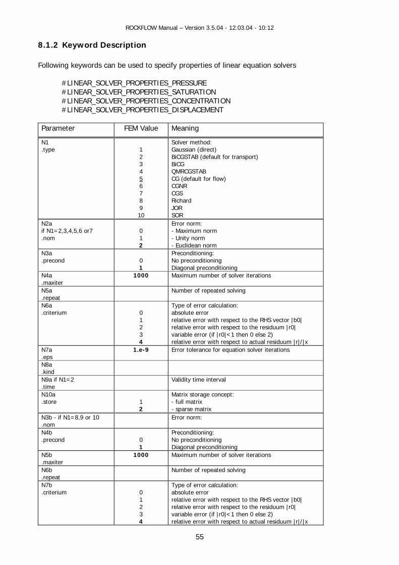
8.1.2 Keyword Descript Following keywords can be used to specify properties of linear equation solvers
#LINEAR_SOLVER_PROPERTIES_PRESSURE #LINEAR_SOLVER_PROPERTIES_SATURATION #LINEAR_SOLVER_PROPERTIES_CONCENTRATION #LINEAR_SOLVER_PROPERTIES_DISPLACEMENT
Parameter FEM Value Meaning
ion
N1 .type
1 2 3 4 56 7 8 9 10
Solver method: Gaussian (direct) BiCGSTAB (default for transport) BiCG QMRCGSTAB CG (default for flow) CGNR CGS Richard JOR SOR
N2a if N1=2,3,4,5,6 or7 .nom
0 1 2
Error norm: - Maximum norm - Unity norm - Euclidean norm
N3a .precond
0 1
Preconditioning: No preconditioning Diagonal preconditioning
N4a .maxiter
1000 Maximum number of solver iterations
N5a .repeat
Number of repeated solving
N6a .criterium
0 1 2 3 4
Type of error calculation: absolute error relative error with respect to the RHS vector |b0| relative error with respect to the residuum |r0| variable error (if |r0|<1 then 0 else 2) relative error with respect to actual residuum |r|/|x
N7a .eps
1.e-9 Error tolerance for equation solver iterations
N8a .kind
N9a if N1=2 .time
Validity time interval
N10a .store
1 2
Matrix storage concept: - full matrix - sparse matrix
N3b - if N1=8,9 or 10 .nom
Error norm:
N4b .precond
0 1
Preconditioning: No preconditioning Diagonal preconditioning
N5b .maxiter
1000 Maximum number of solver iterations
N6b .repeat
Number of repeated solving
N7b .criterium
0 1 2 3 4
Type of error calculation: absolute error relative error with respect to the RHS vector |b0| relative error with respect to the residuum |r0| variable error (if |r0|<1 then 0 else 2) relative error with respect to actual residuum |r|/|x
55

ROCKFLOW Manual – Version 3.5.04 - 12.03.04 - 10:12
N8b .eps
1.e-9 Error tolerance for equation solver iterations
N9b .theta
2 0 [0,1] Relaxation factor for Richardson,JOR,and SOR solver
56

ROCKFLOW Manual – Version 3.5.04 - 12.03.04 - 10:12
8.1.3 Ressource Description
sol.h/ccp CSolverLinear
rfsolver.h/c LINEAR_SOLVER_PROPERTIES
Source file sh_Class Base class CPropertyPage Ressource-ID IDD_SOLVER_LINEAR Control elements Member variables Member RF-variables
functions OnInitDialog() IDC_EDIT_SOL_1 m_strName .name IDC_EDIT_SOL_2 m_dRelaxationFactor .theta IDC_EDIT_SOL_3 m_dErrorTolerance .eps IDC_EDIT_SOL_4 m_lMaximumIterations .maxiter IDC_EDIT_SOL_5 m_lRepeatedSolving .repeat IDC_EDIT_SOL_6 m_dValidTimeInterval .time IDC_CHECK_SOL_1 m_bRenumber umnummerierer IDC_CHECK_SOL_2 m_bPreconditioner .precond IDC_CHECK_SOL_3 m_bMatrixStorage .store IDC_RADIO_SOL_1 m_iSolverTypeRadioButton .type IDC_RADIO_SOL_E1 m_iErrorType .criterium OnOK()
Recommendations: Use BiCGSTAB not for steady flow (large iteration number due to insufficient start approximation)
57

ROCKFLOW Manual – Version 3.5.04 - 12.03.04 - 10:12
8.1.4 GUI Functions 8.1.4.1 View Functions
mdUI* pCmdUI) oid CRockflowView::OnSolverFluidFlowSaturation()
CCmdUI* pCmdUI)
dUI* pCmdUI) ssTransport()
UpdateSolverMassTransport(CCmdUI* pCmdUI)
.1.4.2 Dialog Data Exchange and Messages
String CSolverLinearNew::Get_RF2Dialog_Object(CString m_strName) oid CSolverLinearNew::Set_Dialog2RF_Object(void)
oid CSolverLinearNew::DoDataExchange(CDataExchange* pDX) OOL CSolverLinearNew::OnInitDialog() oid CSolverLinearNew::OnOK()
.1.4.3 Auxiliary Functions
t CSolverLinearNew::GetObjectType(int type) t CSolverLinearNew::SetObjectType(int selected_radio_button)
void CRockflowView::OnSolverFluidFlowPressure() oid CRockflowView::OnUpdateSolverFluidFlowPressure(CCv
vvoid CRockflowView::OnUpdateSolverFluidFlowSaturation(
lowvoid CRockf View::OnSolverHeatTransport() lverHeatTransport(CCmvoid CRockflowView::OnUpdateSo
oid CRockflowView::OnSolverMavvoid CRockflowView::On 8 Cv vBv 8 inin
58

ROCKFLOW Manual – Version 3.5.04 - 12.03.04 - 10:12
8.2 Non-Linear Solver
Concept
.2.1.1 Data Object
8.2.1 Data Non-linear solver are developed to solve non-linear PDEs. Object: NONLINEAR_SOLVER_PROPERTIES Object list: LIST_NONLINEAR_SOLVER_PROPERTIES Source: rfsolver.h/c 8
List *nlsp list typed c
ef struct { har *name;
g type; g maxiter;
riterium; abs_eps; rel_eps; rel_cg_eps; heta; mble; ime;
long kind; } NONLINEAR_SOLVER_PROPERTIES;
lon lon
*nlsp long c double double double double t
*nlsp int asse double t
*nlsp
typedef struct { char *name; List *nlsp_list; long count_of_nonlinear_solver_properties; char **names_of_nonlinear_solver_properties; long count_of_nonlinear_solver_properties_name; double *nlsp_vector; } LIST NONLINEAR SOLVER PROPERTIES;
59

ROCKFLOW Manual – Version 3.5.04 - 12.03.04 - 10:12
8.2.1.2 Object Names Keywo
_properties_water_content; ar *keyword_nonlinear_solver_properties_saturation; ar *keyword_nonlinear_solver_properties_tracer_component;
_solver_properties_solute_component; ar *keyword_nonlinear_solver_properties_sorbed_component;
*keyword_nonlinear_solver_properties_temperature_phase;
ar *name_nonlinear_solver_properties_fluid_phase; me_nonlinear_solver_properties_water_content; me_nonlinear_solver_properties_saturation;
s_tracer_component; s_solute_component;
ar *GetDefaultNameNonLinearSolverPropertiesFluidPhase(int number);
ertiesTracerComponent(int number); ertiesSoluteComponent(int number);
ar *Gar *G
redefined LSP object names
ER_PROPERTIES_FLUID_PHASE(i) \ tiesFluidPhase(i)
define DEFAULT_NAME_NONLINEAR_SOLVER_PROPERTIES_TRACER_COMPONENT(i) \ GetDefaultNameNonLinearSolverPropertiesTracerComponent(i)
_NONLINEAR_SOLVER_PROPERTIES_SORBED_COMPONENT(i) \ GetDefaultNameNonLinearSolverPropertiesSorbedComponent(i)
T(i) \
define DEFAULT_NAME_NONLINEAR_SOLVER_PROPERTIES_SATURATION(i) \ GetDefaultNameNonLinearSolverPropertiesSaturation(i) #define DEFAULT_NAME_NONLINEAR_SOLVER_PROPERTIES_WATER_CONTENT(i) \ GetDefaultNameNonLinearSolverPropertiesWaterContent(i) #define DEFAULT_NAME_NONLINEAR_SOLVER_PROPERTIES_TEMPRATURE(i) \ GetDefaultNameNonLinearSolverPropertiesTemperaturePhase(i)
rds char *keyword_nonlinear_solver_properties_fluid_phase; char *keyword_nonlinear_solverchchchar *keyword_nonlinearchchar Objects chchar *nahar *nac
char *name_nonlinear_solver_propertiechar *name_nonlinear_solver_propertiechar *name_nonlinear_solver_properties_sorbed_component; char *name_nonlinear_solver_properties_temperature_phase; Access chchar *GetDefaultNameNonLinearSolverPropertiesWaterContent(int number); har *GetDefaultNameNonLinearSolverPropertiesSaturation(int number); c
char *GetDefaultNameNonLinearSolverPropchar *GetDefaultNameNonLinearSolverPropch etDefaultNameNonLinearSolverPropertiesSorbedComponent(int number);
etDefaultNameNonLinearSolverPropertiesTemperaturePhase(int number); ch Makros for p #define DEFAULT_NAME_NONLINEAR_SOLV GetDefaultNameNonLinearSolverProper# #define DEFAULT_NAME #define DEFAULT_NAME_NONLINEAR_SOLVER_PROPERTIES_SOLUTE_COMPONEN GetDefaultNameNonLinearSolverPropertiesSoluteComponent(i) #
60
ROCKFLOW Manual – Version 3.5.04 - 12.03.04 - 10:12
Construction of LSP names
esNames (char *sys_name, int number_of_phases, int number_of_components);
jekt-Namen konfigurieren */
ist
ar *data, int found, FILE * f); har *data, int found, FILE * f);
on(char *data, int found, FILE * f);
char *name);
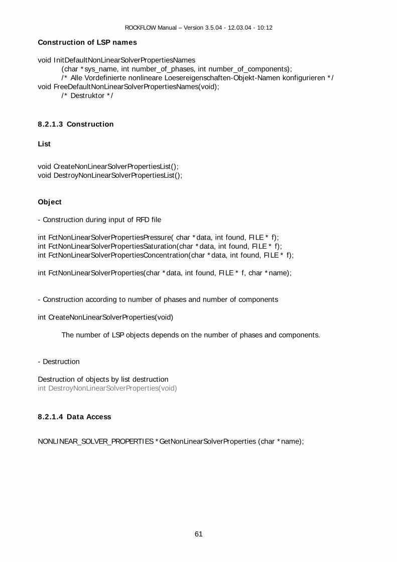
Co components int CreateNonLinearSolverProperties(void)
The number of LSP objects depends on the number of phases and components. - Destruction Destruction of objects by list destruction int DestroyNonLinearSolverProperties(void) 8.2.1.4 Data Access
NONLINEAR_SOLVER_PROPERTIES *GetNonLinearSolverProperties (char *name);
void InitDefaultNonLinearSolverProperti
/* Alle Vordefinierte nonlineare Loesereigenschaften-Oboid FreeDefaultNonLinearSolverPropertiesNames(void); v
/* Destruktor */ 8.2.1.3 Construction L
void CreateNonLinear tiesList(); SolverPropervoid DestroyNonLinearSolverPropertiesList(); Object - Construction during input of RFD file int FctNonLinearSolverPropertiesPressure( ch
lverPropertiesSaturation(cint FctNonLinearSoint FctNonLinearSolverPropertiesConcentrati int FctNonLinearSolverProperties(char *data, int found, FILE * f, - nstruction according to number of phases and number of
61
ROCKFLOW Manual – Version 3.5.04 - 12.03.04 - 10:12
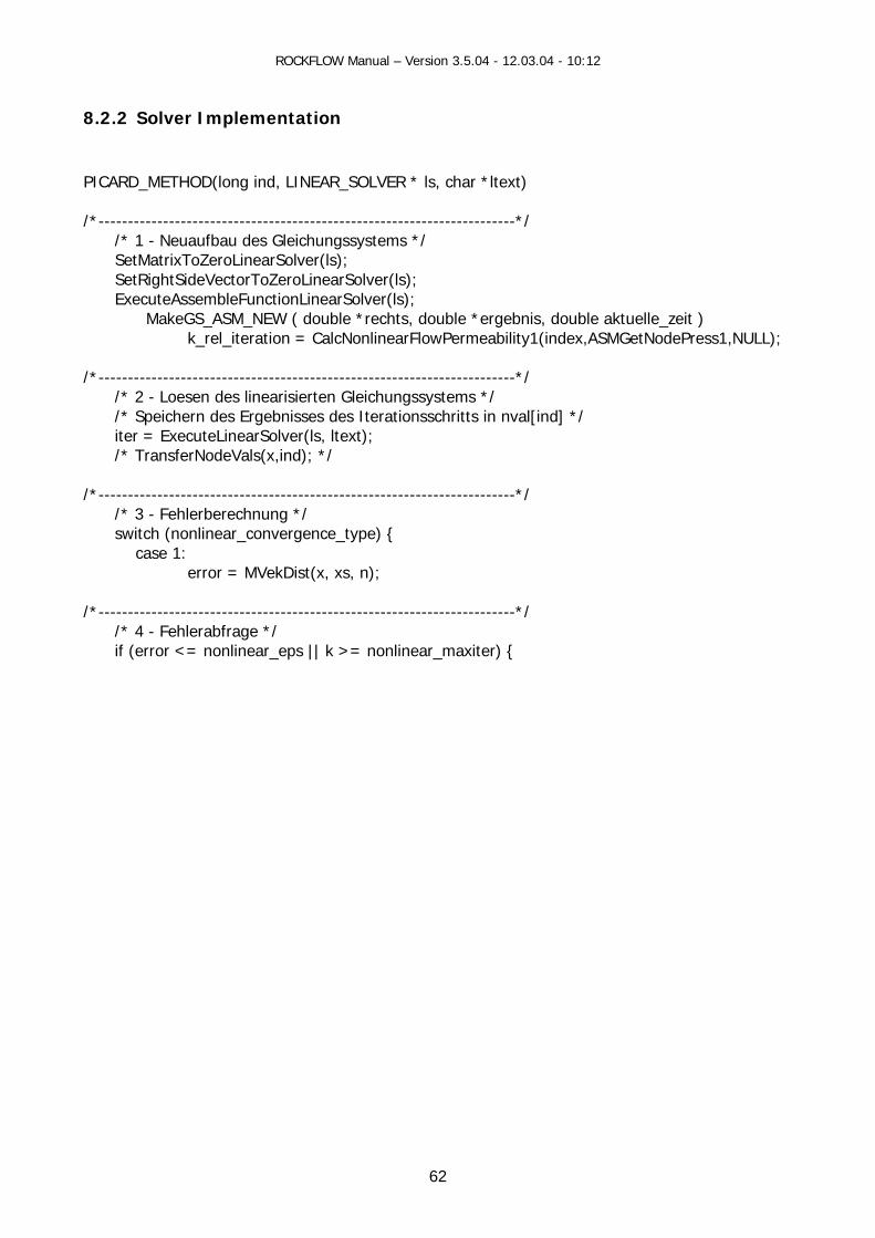
8.2.2 Solver Implementation
PICARD text) /*------
/* 1 - Neuaufbau des Gleichungssystems */ SetMatrixToZeroLinearSolver(ls);
SetRightSideVectorTo lv ExecuteAssembleFunctionLinearSolver(ls); MakeGS_ASM_NEW ( double *re gebnis, double aktuelle_zeit )
k_rel_iteration = CalcNonl ex,ASMGetNodePress1,NULL);
/ ----------------------------- ------- - Loesen des linearisierten Gleichungssystems */ Ite / iter = ExecuteLinearSolver(ls, ltext); /* TransferNodeVals(x,ind); */ /*- -------------------------------------- berechnung near_convergence_type case 1: error = MVekDist(x, xs, n) / -------------------------------------- / abfrage */ (error <= nonlinear_eps || k >= nonlinear_maxiter) {
_METHOD(long ind, LINEAR_SOLVER * ls, char *l
-----------------------------------------------------------------*/
ZeroLinearSo er(ls);
chts, double *erinearFlowPermeability1(ind
*---- ------- ------------------------*/ /* 2/* Speichern des Ergebnisses des rationsschritts in nval[ind] *
---/* 3 - Fehler----- ------------------------*/
) { */
switch (nonli
;
*--------- ------------------------*/* 4 - Fehlerif
62

ROCKFLOW Manual – Version 3.5.04 - 12.03.04 - 10:12
8.2.3 Keyword Description Following keywords can b ify properties non-linear equ
LINEAR_SO ES_PRESSURE NEAR_SOL RATION
R_SOL CONCE
Meaning
e used to spec of ation solvers
#NON LVER_PROPERTI#NONLI VER_PROPERTIES_SATU#NONLINEA VER_PROPERTIES_ NTRATION
Parameter FEM Value
N1 .type
Solver m1 - Pic2 - N
eth : ard fixpoint iteration
ewton-Ra hson method
od
pN2 .maxiter
100 Maximum nu ber of solver item rations
N3 .criterium
T0 - d1 - di
ype of erro alculation: ifference result vector fference residuum
r cinin
N4 .abs_eps 1.e-6 Absolute err lerance for non-linear solver
ions or to
iteratN.rel_ep
5 s 1.e-3 e for non-linear solver
iterations Relative error toleranc
N6 .rel_cg_eps 0.0 Combined error tolerance for non-linear solver
iterations with respect to linear solver iterations N7 .assemble 1 Number of iterations before reassembling the
system of equation N8 .time
-1 Validity time
N9 .kind
0 Validity time model
63
ROCKFLOW Manual – Version 3.5.04 - 12.03.04 - 10:12
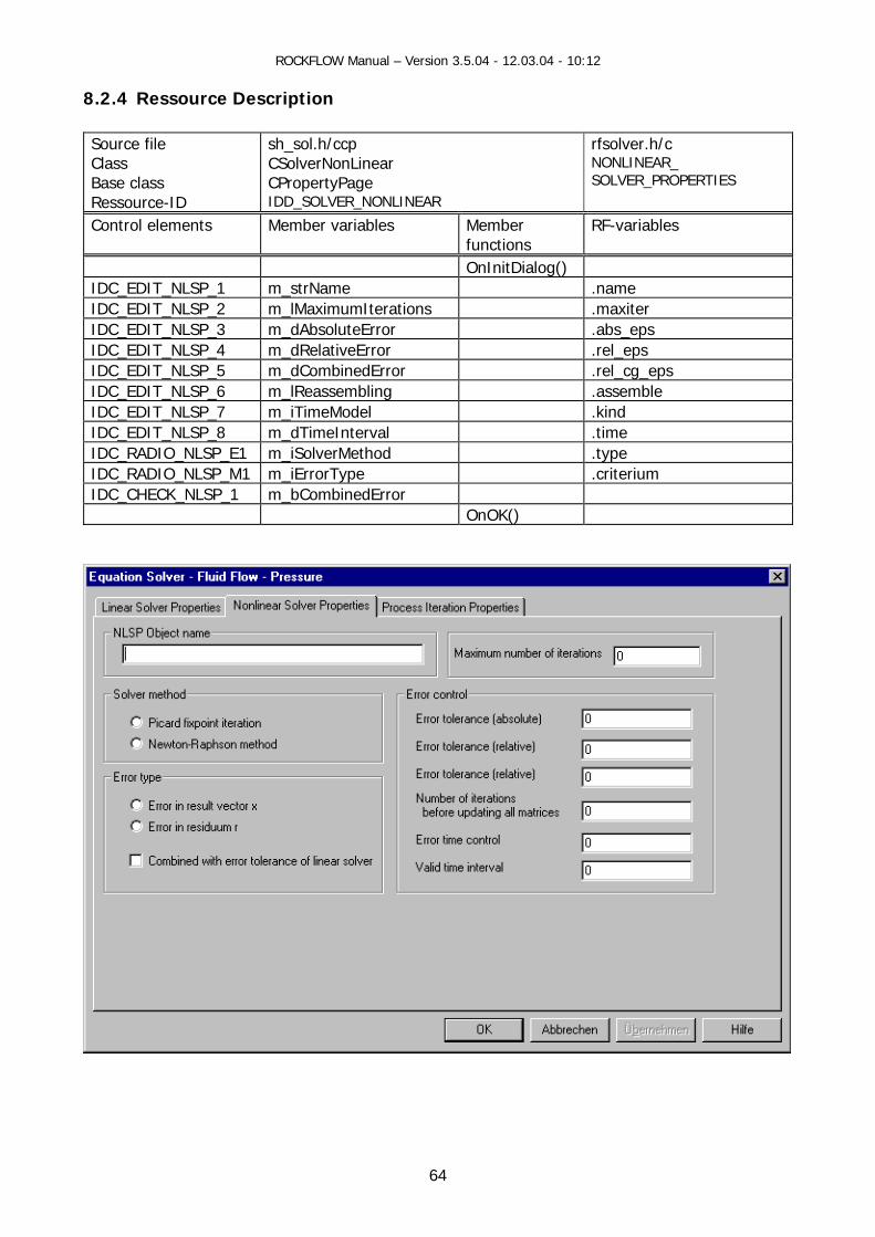
8.2.4 Ressource Description
_sol.h/ccp CSolverNonLinear
rfsolver.h/c NONLINEAR_ SOLVER_PROPERTIES
Source file shClass Base class CPropertyPage Ressource-ID IDD_SOLVER_NONLINEAR
Control elements Member variables Member RF-variables functions
OnInitDialog() IDC_EDIT_NLSP_1 m_strName .name IDC_EDIT_NLSP_2 m_lMaximumIterations .maxiter IDC_EDIT_NLSP_3 m_dAbsoluteError .abs_eps IDC_EDIT_NLSP_4 m_dRelativeError .rel_eps IDC_EDIT_NLSP_5 m_dCombinedError .rel_cg_eps IDC_EDIT_NLSP_6 m_lReassembling .assemble IDC_EDIT_NLSP_7 m_iTimeModel .kind IDC_EDIT_NLSP_8 m_dTimeInterval .time IDC_RADIO_NLSP_E1 m_iSolverMethod .type IDC_RADIO_NLSP_M1 m_iErrorType .criterium IDC_CHECK_NLSP_1 m_bCombinedError OnOK()
64
ROCKFLOW Manual – Version 3.5.04 - 12.03.04 - 10:12
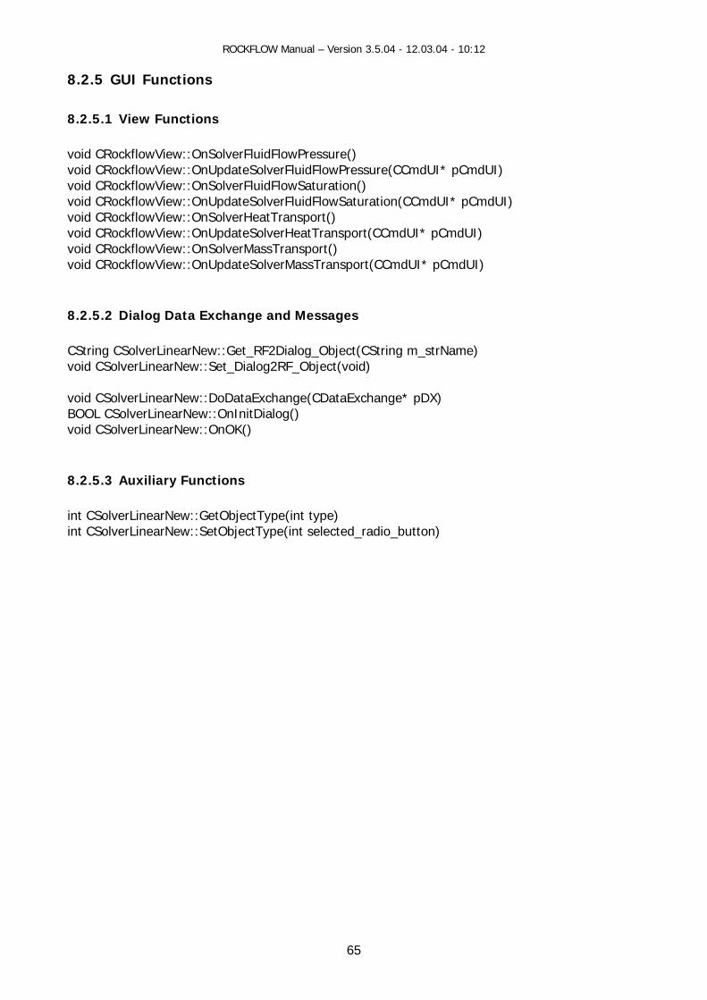
8.2.5 GUI Functions
.2.5.1 View Functions
teSolverFluidFlowPressure(CCmdUI* pCmdUI) oid CRockflowView::OnSolverFluidFlowSaturation() oid CRockflowView::OnUpdateSolverFluidFlowSaturation(CCmdUI* pCmdUI)
olverHeatTransport() oid CRockflowView::OnUpdateSolverHeatTransport(CCmdUI* pCmdUI)
ow sport(CCmdUI* pCmdUI)
.2.5.2 Dialog Data Exchange and Messages
String CSolverLinearNew::Get_RF2Dialog_Object(CString m_strName) oid CSolverLinearNew::Set_Dialog2RF_Object(void)
oid CSolverLinearNew::DoDataExchange(CDataExchange* pDX) OOL CSolverLinearNew::OnInitDialog() oid CSolverLinearNew::OnOK()
.2.5.3 Auxiliary Functions
t CSolverLinearNew::GetObjectType(int type) t CSolverLinearNew::SetObjectType(int selected_radio_button)
8 void CRockflowView::OnSolverFluidFlowPressure() void CRockflowView::OnUpdavvvoid CRockflowView::OnSvvoid CRockflowView::OnSolverMassTransport() void CRockfl View::OnUpdateSolverMassTran 8 Cv vBv 8 inin
65

ROCKFLOW Manual – Version 3.5.04 - 12.03.04 - 10:12
8.3 Iteration Process
general, multiphase-multicomponental processes cover a system of coupled non-linear PDEs. To low e can
ITERATION_PROPERTIES (IP) bject list: LIST_ITERATION_PROPERTIES
Insolve the whole system of equations (i.e. , mass and/or heat transport equaf tions), wspecify iteration parameters.
8.3.1 Data Concept Object: OSource: rfiter.h/c 8.3.1.1 Data Organization
List *ip list
*ip
*ip
*ip
typedef struct { char *name; List *ip_list; long count_of_iteration_properties char **names_of_iteration_properti long count_of_iteration_properties double *ip_vector;
PERTIES; } LIST_ITERATION_PRO
6
typedef struct {
double fac_eps; double exp_eps; long kind;
ps;
*values;
_PROPERTIES;
char *name; long type; int norm; long maxiter; double abs_eps; double rel_eps; double var_eps; double begin_eps; double end_eps;
long criterium;
double rel_cg_e double theta; double time; long level; long count_of_values; double long distribution_type; } ITERATION
; es; _name;
6
ROCKFLOW Manual – Version 3.5.04 - 12.03.04 - 10:12
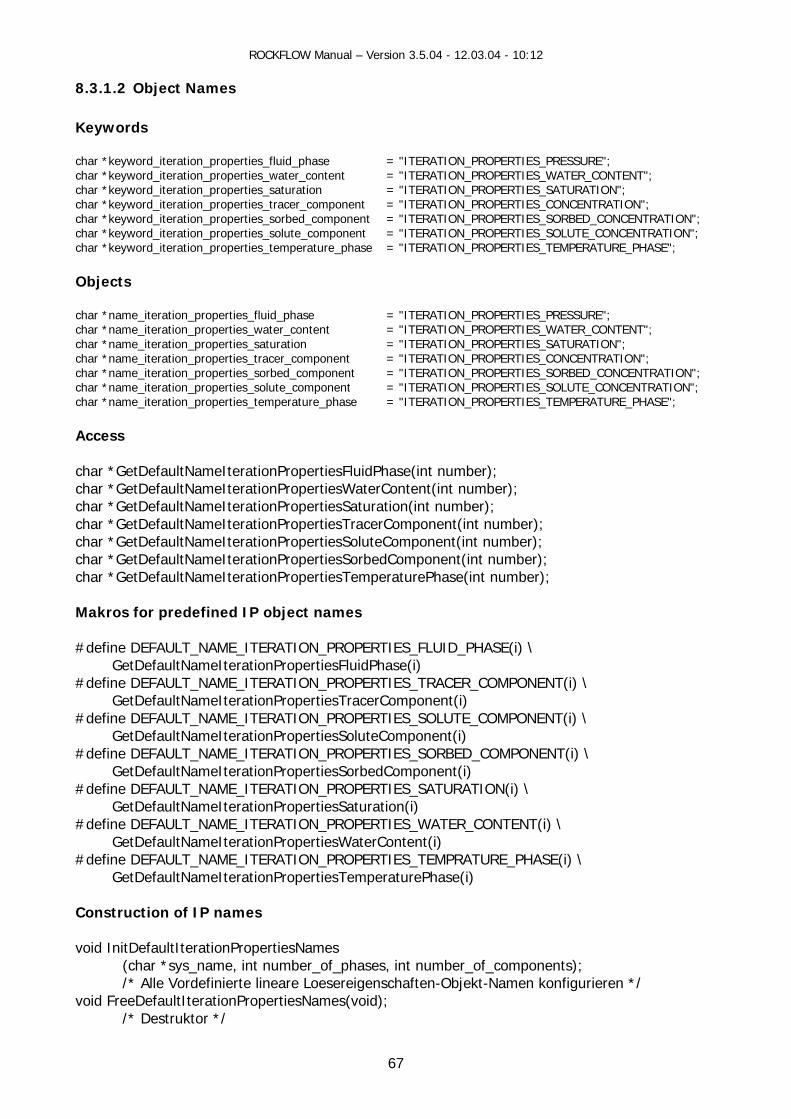
8.3.1.2 Object Names
ords
se = "ITERATION_PROPERTIES_PRESSURE"; WATER_CONTENT";
char *ke IES_SATURATION"; = "ITERATION_PROPERTIES_CONCENTRATION";
PERTIES_SORBED_CONCENTRATION"; ar *key SOLUTE_CONCENTRATION";
ord_iteration_properties_temperature_phase = "ITERATION_PROPERTIES_TEMPERATURE_PHASE";
char *naar *name_iteration_properties_water_content = "ITERATION_PROPERTIES_WATER_CONTENT";
e_iteration_properties_saturation = "ITERATION_PROPERTIES_SATURATION"; ar *name_iteration_properties_tracer_component = "ITERATION_PROPERTIES_CONCENTRATION";
nent = "ITERATION_PROPERTIES_SORBED_CONCENTRATION"; ent = "ITERATION_PROPERTIES_SOLUTE_CONCENTRATION";
ar *name_iteration_properties_temperature_phase = "ITERATION_PROPERTIES_TEMPERATURE_PHASE";
ar *GetDefaultNameIterationPropertiesSaturation(int number);
ar *GetDefaultNameIterationPropertiesSoluteComponent(int number);
ar *GetDefaultNameIterationPropertiesTemperaturePhase(int number);
akros for predefined IP object names
define DEFAULT_NAME_ITERATION_PROPERTIES_FLUID_PHASE(i) \ luidPhase(i)
_PROPERTIES_TRACER_COMPONENT(i) \ GetDefaultNameIterationPropertiesTracerComponent(i) define DEFAULT_NAME_ITERATION_PROPERTIES_SOLUTE_COMPONENT(i) \
rationPropertiesSoluteComponent(i) define DEFAULT_NAME_ITERATION_PROPERTIES_SORBED_COMPONENT(i) \
GetDefaultNameIterationPropertiesSaturation(i) define DEFAULT_NAME_ITERATION_PROPERTIES_WATER_CONTENT(i) \
GetDefaultNameIterationPropertiesWaterContent(i) #define DEFAULT_NAME_ITERATION_PROPERTIES_TEMPRATURE_PHASE(i) \ GetDefaultNameIterationPropertiesTemperaturePhase(i) Construction of IP names void InitDefaultIterationPropertiesNames
(char *sys_name, int number_of_phases, int number_of_components); /* Alle Vordefinierte lineare Loesereigenschaften-Objekt-Namen konfigurieren */
void FreeDefaultIterationPropertiesNames(void); /* Destruktor */
Keyw char *keyword_iteration_properties_fluid_phachar *keyword_iteration_properties_water_content = "ITERATION_PROPERTIES_
yword_iteration_properties_saturation = "ITERATION_PROPERTchar *keyword_iteration_properties_tracer_component char *keyword_iteration_properties_sorbed_component = "ITERATION_PRO
word_iteration_properties_solute_component = "ITERATION_PROPERTIES_chchar *keyw Objects
me_iteration_properties_fluid_phase = "ITERATION_PROPERTIES_PRESSURE"; chchar *namchchar *name_iteration_properties_sorbed_compochar *name_iteration_properties_solute_componch Access char *GetDefaultNameIterationPropertiesFluidPhase(int number); char *GetDefaultNameIterationPropertiesWaterContent(int number); chchar *GetDefaultNameIterationPropertiesTracerComponent(int number); chchar *GetDefaultNameIterationPropertiesSorbedComponent(int number); ch
M # GetDefaultNameIterationPropertiesF#define DEFAULT_NAME_ITERATION # GetDefaultNameIte# GetDefaultNameIterationPropertiesSorbedComponent(i) #define DEFAULT_NAME_ITERATION_PROPERTIES_SATURATION(i) \ #
67
ROCKFLOW Manual – Version 3.5.04 - 12.03.04 - 10:12
8.3.1.3 Construction List void Cr
ustaende */ extern ende */ Group
t DestroyIterationPropertiesListGroup(char *name); ERATION_PROPERTIES-Objekte der Gruppe NAME */
O - truction during input of R file int FctIterationProperties ( cha ata, inint Fct tiesPressure( char *i ropertiesSatura n(charint FctIterationPropertiesConce ation(c d, FILE * f); int FctIterationPropertiesSorbe ncentr nt found, FILE * f); - uction according to number of phases and number of components int CreateIterationProperties(number_of_phases, number_of_components);
ber of IP object depend components. - Destruction Destruction of objects by list tioni erationPropertie 8.3.1.4 Data Access I TION_PROPERTIES *Get rationP r *name,ITERATION_PROPERTIES *ip);
eateIterationPropertiesList(); /* Erzeugt leere unbenannte Liste von Anfangszvoid DestroyIterationPropertiesList(); /* Zerstoert unbenannte Liste von Anfangszusta
in/* Zerstoert saemtliche IT
bject
Cons FD
r d * t found, FILE *f ); data, int found, FILE * f); IterationProper
nt FctIterationP tio *data, int found, FILE * f); ntr har *data, int foundCo ation(char *data, i
Constr
The num s s on the number of phases and
destruc nt DestroyIt s(void)
TERA Ite ropertiesGroup(cha
68
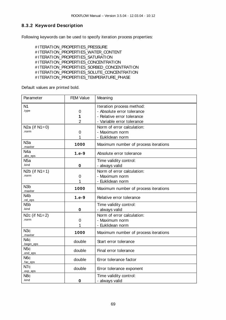
ROCKFLOW Manual – Version 3.5.04 - 12.03.04 - 10:12
8.3.2 Keyword Description Following keywords can be u iteration pr erties:
RATION_PROPE E ION_PROPE
_PROPE N #ITERATION_PROPERTIES_CONCENTRATION #ITERATION_PROPE TIES_SORBED_CONCENT
ROPE TE_CONCENTROPE H SE
D ed bo
FE aning
sed to specify ocess prop
#ITE RTIES_PRESSUR#ITERAT RTIES_WATER_CONTENT #ITERATION RTIES_SATURATIO
R RATION ATION #ITERATION_P RTIES_SOLU R
#ITERATION_P RTIES_TEMPERATURE_P A
efault values are print ld.
Parameter M Value Me
N1 .type
Iterat0 - Absolu1 - Relative2 - Variable e
ion proc hod: te err tolerance error tolerance
rror tolerance
ess metor
N2a (if N1=0) .norm
Norm of 0 - M1 - E
error alculation: aximum norm uklidean norm
c
N3a er
000 Maximum num rocess it ations 1 ber of p er.maxit
N4a .abs_eps
1.e-9 Absolute error tolerance
N5a .kind
0
Time validity control: - always valid
N2b (if N1=1) .norm
0 1
Norm of error calculation: - Maximum norm - Euklidean norm
N3b .maxiter
1000 Maximum number of process iterations
N4b .rel_eps
1.e-9 Relative error tolerance
N5b .kind
0
Time validity control: - always valid
N2c (if N1=2) .norm
0 1
Norm of error calculation: - Maximum norm - Euklidean norm
N3c .maxiter
1000 Maximum number of process iterations
N4c .begin_eps
double Start error tolerance
N5c .end_eps
double Final error tolerance
N6c .fac_eps
double Error tolerance factor
N7c .exp_eps
double Error tolerance exponent
N8c .kind
0
Time validity control: - always valid
69

ROCKFLOW Manual – Version 3.5.04 - 12.03.04 - 10:12
8.3.3 Ressource Description
sh_sol.h/ccp CSolverIteration CPropertyPage
rfiter.h/c ITERATION_PROPERTIES
Source file Class Base class Ressource-ID IDD_SOLVER_ITERATION
Control elements Member variables Member RF-vafunctions
riables
OnInitDialog() IDC_EDIT_SOL_IP_1 m_strName .name IDC_EDIT_SOL_IP_2 m_lMaximumIterations .maxiter IDC_EDIT_SOL_IP_3 m_dAbsoluteError .abs_eps IDC_EDIT_SOL_IP_4 m_dRelativeError .rel_eps IDC_EDIT_SOL_IP_5 m_dErrorStart .begin_eps IDC_EDIT_SOL_IP_6 m_dErrorFinal .end_eps IDC_EDIT_SOL_IP_7 m_dErrorFactor .fac_eps IDC_EDIT_SOL_IP_8 m_dErrorExponent .exp_eps IDC_EDIT_SOL_IP_9 m_iErrorTimeControl .kind IDC_EDIT_SOL_IP_10 m_dErrorTimeInterval .time IDC_RADIO_SOL_IP_M1 m_iIterationMethod .type IDC_RADIO_SOL_IP_N1 m_iErrorNorm .norm IDC_RADIO_SOL_IP_T1 m_iErrorType .criterium OnOK()
70
ROCKFLOW Manual – Version 3.5.04 - 12.03.04 - 10:12
8.3.4 GUI Functions 8.3.4.1 View Functions
oid CRockflowView::OnUpdateSolverFluidFlowSaturation(CCmdUI* pCmdUI) void CRockflowView::OnSolverHeatTransport() void CRockflowView::OnUpdateSolverHeatTransport(CCmdUI* pCmdUI) void CRockflowView::OnSolverMassTransport() void CRockflowView::OnUpdateSolverMassTransport(CCmdUI* pCmdUI)
.3.4.2 Dialog Data Exchange and Messages
String CSolverIteration::Get_RF2Dialog_Object(CString m_strName) ialog2RF_Object(void)
oid CSolverIteration::DoDataExchange(CDataExchange* pDX)
It
void CSolverIteration::StatusDialogResourceElements(void)
void CRockflowView::OnSolverFluidFlowPressure() void CRockflowView::OnUpdateSolverFluidFlowPressure(CCmdUI* pCmdUI) oid CRockflowView::OnSolverFluidFlowSaturation() v
v
8 Cvoid CSolverIteration::Set_D vBOOL CSolverIteration::OnInitDialog() void CSolver eration::OnOK() 8.3.4.3 Auxiliary Functions
71
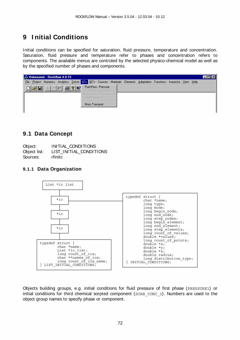
ROCKFLOW Manual – Version 3.5.04 - 12.03.04 - 10:12
9 Initial Conditions
can be specified for satura e, t ture and concentration. mperatur refer to phases and concentration refers to
trol h l as well as and compo
Initial conditions tion, fluid pressur emperaSaturation, fluid pressure and te ecomponents. The available menus are con ed by the selected p ysico-chemical modeby the specified number of phases nents.
9.1 Data Concept
bject list: LIST_INITIAL_CONDITIONS ources: rfinitc
.1.1 Data Organization
Objects building groups, e.g. initial conditions for fluid pressure of first phase (PRESSURE1) or initial conditions for third chemical sorpted component (SORB_CONC_3). Numbers are used to the object group names to specify phase or component.
Object: INITIAL_CONDITIONS OS 9
List *ic list
typedef struct { char *name; long type;
element; long end_element;
long count_of_values; double *values; long count_of_points; double *x; double *y; double *z; double radius; long distribution_type;
*ic
*ic
long mode; long begin_node; long end_node; *ic long step_nodes; long begin_
long step_elements;
typedef struct { char * List * long count_of_ics;
name; ic_list;
char **names_of_ics; } INITIAL_CONDITIONS; long count_of_ics_name;
} LIST_INITIAL_CONDITIONS;
72

ROCKFLOW Manual – Version 3.5.04 - 12.03.04 - 10:12
9.1.2 Object Names RF-FEM variable RF-Shell variable Value name_ PRESSURE initial_condition_fluid_phase name_ WATER_CONTENT initial_condition_water_content name_ SATURATION initial_condition_saturation name_ CONC_ initial_condition_tracer_component name_initial_condition_solute_component SOLU_CONC_ name_initial_condition_sorbed_component SORB_CONC_ name_initial_condition_temperature_phase
nitialConditions ic.m_strICName
TEMPERATURE
CIm_
Data type: char * Data type: Cstring 9.1.3 Data truction 9.1.3.1 List void CreateInitialConditionsList(void) void DestroyInitialConditionsList(void) 9.1.3.2 Grou int DestroyIni onsListItem(char *name); 9.1.3.3 Obje From RFD file
int Fct nditionNew(char *data,FILE *f,char *ic_name,char *string,int found) B ialog
ITIA IONS* AddInitialC
i yIni Object( ng co
9.1.4 Data ess INITIAL_CON NS *GetInitialConditionsList(char *name,INITIAL_CONDITIONS *ic); INITIAL_CON *GetInitialConditionsObject(long count,char *name); I CON ONS *GetInitialC nditio
Cons
p
tialConditi
ct
InitialCo
y GUI dIN
L_CONDIT onditionsObject(char *name);
nt Destro tialConditions lo unt,char *name);
Acc
DITIODITIONS
NITIAL_ DITI o nsObjectCount(long count,char *name);
73

ROCKFLOW Manual – Version 3.5.04 - 12.03.04 - 10:12
9.2 Keyword Description The following keywords are a ify initial conditions for fluid flow, he t transport and
ransport.
L_CONDITIONCONDITION
L_CONDITIONS_TEMPERATURE L_CONDITION TRATION
se of the key conditions for corresponding phases a
F Variable Meaning
vailable to spec amass t
#INITIA S_PRESSURE #INITIAL_ S_SATURATION #INITIA#INITIA S_CONCEN
By repeatedly u words, initial nd compo-nents are specified. Parameter R Defaults
N1 type Initial value is specified for all nodes 0
N2 mode
Overwrite Superimpose
0 1
if N1=0 values[0] Constant value to all nodes if N1=1 begin_node
es[0] Value for individu nodes given by node num
valu al ber first
node if N1=2 x[0]
z[0]
dividu nodes given by coordinates y[0]
values[0]
Value for in al
if N1=3 begin_node end_node step_nodes values[0]
Linear value distr two given First node, secon f nodes in b
ibution betwee node, count o
n nodes: d etween
if N1=4 x[0] y[0] z[0] values[0] x[1] y[1] z[1] values[1]
Linear value distr en by coordinates ibution on a line giv
if N1=5 z[0] values[0]
Hydrostatic distribution to all nodes by pressure
if N1=6 z[0] values[0]
Hydrostatic distribution to all nodes by z-coordinate
if N1=7 begin_node distribution_type radius values[0]
Block entries by node number
if N1=8 x[0] y[0] z[0] distribution_type radius values[0]
block entries by node coordinates
if N1=9 x[0] y[0] z[0] x[1] y[1] z[1] x[2] y[2] z[2] values[0]
Constant value at a plain given by coordinates
74

ROCKFLOW Manual – Version 3.5.04 - 12.03.04 - 10:12
9.3 Ressource Description Source file Class Base class Ressource-ID
sh_ic.h/ *.ccp CInitialConditions CPropertyPage IDD_INITIAL_CONDITIONS
Control elements Member variables Member functions RF-variables IDC_EDIT_IC_1 m_strICName ->name IDC_EDIT_IC_2 m_lNode1 ->begin_node IDC_EDIT_IC_3 m_lNode2 ->end_node IDC_EDIT_IC_4 m_lElement1 ->begin_element IDC_EDIT_IC_5 m_lElement2 ->end_element IDC_EDIT_IC_6 m_iStepInterval IDC_EDIT_IC_7 m_dPoint1x ->x[0] IDC_EDIT_IC_8 m_dPoint1y ->y[0] IDC_EDIT_IC_9 m_dPoint1z ->z[0] IDC_EDIT_IC_10 m_dPoint2x ->x[1] IDC_EDIT_IC_11 m_dPoint2y ->y[1] IDC_EDIT_IC_12 m_dPoint2z ->z[1] IDC_EDIT_IC_13 m_dValue1 ->values[0] IDC_EDIT_IC_14 m_dValue2 ->values[1] IDC_EDIT_IC_15 m_dRadius ->radius IDC_EDIT_IC_16 m_dStandardDeviation IDC_EDIT_IC_18 m_strICComponent IDC_LIST_IC m_ListICPressure OnSelchangeICList() IDC_RADIO_IC_TYPE1- IDC_RADIO_IC_TYPE7
m_iICSelectedType OnRadioIC1()- OnRadioIC7()
->type
IDC_RADIO_IC_MODE1- IDC_RADIO_IC_MODE2
m_iICMode ->mode
IDC_RADIO_IC_QUANTITIES1 IDC_RADIO_IC_QUANTITIES2
m_iICQuantities
IDC_BUTTON_IC_ADD OnButtonICAdd() IDC_BUTTON_IC_UPDATE OnButtonICUpdate() IDC_BUTTON_IC_REMOVE OnButtonICRemove() IDC_BUTTON_IC_REMOVEALL OnButtonICRemoveAll() IDC_BUTTON_IC_SAVE OnButtonICSaveData()
Example: #INITIAL_CONDITIONS_PRESSURE 0 0 3.0000e+000 1 0 2 1.0000e+000 2 0 1.0000e+000 2.0000e+000 3.0000e+000 1.0000e+001 2 0 3.0000e+000 3.0000e+000 3.0000e+000 1.1000e+001 5 0 4.0000e+000 4.0000e+000
75
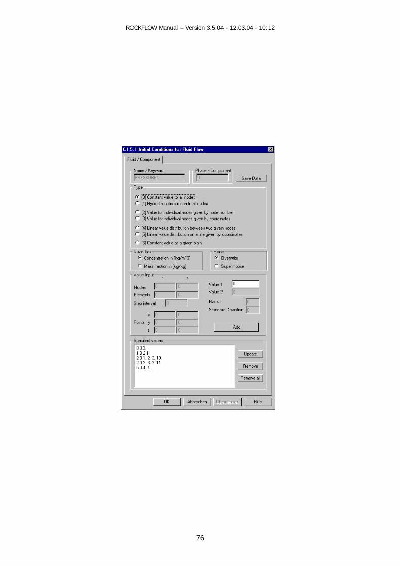
ROCKFLOW Manual – Version 3.5.04 - 12.03.04 - 10:12
76

ROCKFLOW Manual – Version 3.5.04 - 12.03.04 - 10:12
9.4 GUI Data Concept
9.4.1 Class Representation
CInitialConditions
9.4.2 Document Data Concept Document Data Exchange (RF-FEM----CRockflowDoc---RF-Shell) The dialog data are stored in 2-dimensional arrays of CStringLists in CRockflowDoc: CStringList m_strlstListICPressure [0][0] with: d=0 for fluid dialog selected
r=0 for first phase
Tranfers: CRockflowDoc---RF-Shell:
CInitialConditions::OnInitDialog() pActualList =&(m_pDoc-> strlstListICPressure [0][0])
while(pos) m_ListICPressure.AddString(pAktualList->GetNext(pos));
CInitialConditions::OnOK() pAktualList=&(m_pDoc->m_strlstListICPressure[0][0]); //For all entries in Listbox: m_ListICPressure.GetText(i,tmp);
pAktualList->AddTail(tmp); RF-FEM---CRockflowDoc: CRockflowView::OnFileSave() Write_DocToRF_InitialConditions()
{ //for all entries in the CStringLists for all registers an INITIAL_CONDITIONS object(struct) is created and inserted into INITIAL_CONDITIONS_LIST}
CRockflowView::OnFileOpen() CRockflowDoc::WriteRFtoDoc_InitialConditions()
{ // for all INITIAL_CONDITIONS in LIST_INITIAL_CONDITIONS a String is created and inserted in the correct CStringList in Document depending on INITIAL_CONDITION.name}
ocument Concept Data Flow
D
r
OnInitDialog()
OnOK())
class CRockflowDoc { CStringArray[dialog][registe]
77
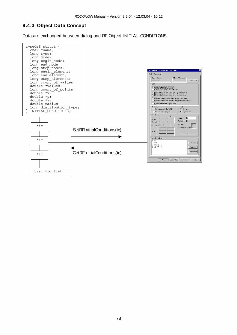
ROCKFLOW Manual – Version 3.5.04 - 12.03.04 - 10:12
9.4.3 Object Data Concept
ata are exchanged between dialog and RF-Object INITIAL_CONDITIONS.
D
typedef struct {
long mode;
double *values; long count_of_points;
double radius;
char *name; long type;
long begin_node; long end_node; long step_nodes; long begin_element; long end_element; long step_elements; long count_of_values;
double *x; double *y; double *z;
long distribution_type; } INITIAL_CONDITIONS;
*ic
*ic
*ic
L
SetRFInitialConditions(ic)
GetRFInitialConditions(ic)
ist *ic list
78
ROCKFLOW Manual – Version 3.5.04 - 12.03.04 - 10:12
9.5 GUI Functions
.5.1 View Functions (CRockflowView)
iew functions connect the mainframe menu (pull-down menu) with the individual dialogs.
oid CRockflowView::OnIcsTemperature() oid CRockflowView::OnIcsConcentration1()
9.5.3 Dialog Data Exchange void CInitialConditions::GetRFInitialConditionsGroup()
// Copies data of all IC objects named m_strICName to protocol list box CString CinitialConditions::GetRFInitialConditionsObject(INITIAL_CONDITIONS *ic)
// Transfers IC object data to dialog data and freshens resource elements void CInitialConditions::SetRFInitialConditions(INITIAL_CONDITIONS *ic) // Transfers dialog data to IC object
9.5.4 Dialog Messages BOOL CInitialConditions::OnInitDialog()
// Transfers data from Objects/Document to the Dialog, fills the protocol list box void CInitialConditions::OnRadioICPress1()
// Activates resource elements for the selected IC object type void CInitialConditions::OnButtonICPressAdd()
// Adds new IC object and build string for the protocol list box // Adds string in the protocol list box(Document concept only)
void CInitialConditions::OnButtonICPressUpdate() // Updates IC object and protocol list box with dialog data
// Updates selected list box string with dialog data(Document concept) void CInitialConditions::OnButtonICPressRemove()
// Removes selected IC object and corresponding protocol list box string // Removes selected protocol list box string(Document concept)
void CInitialConditions::OnButtonICPressRemoveAll() // Removes all IC objects and empties protocol list box
// Removes all list box strings (Document concept) void CInitialConditions::OnSelchangeICList()
// Transfers IC object data to dialog data and freshens resource elements void CInitialConditions::OnButtonICSaveData() // Saves IC object data (only for string concept) void CInitialConditions::OnOK()
9 V void CRockflowView::OnIcsPressure() void CRockflowView::OnIcsSaturation() vv
9.5.2 Document Data Exchange void WriteRF2Doc_InitialConditions(void) void WriteDoc2RF_InitialConditions(void)
79

ROCKFLOW Manual – Version 3.5.04 - 12.03.04 - 10:12
80
// Saves IC object data n Document (Document concept)
9.5 void CinitialConditions::OnAdd_ICDialog(int mode,char *name,CListBox *m_ICList,int type) void CinitialConditions::OnSel_ICDialog(int mode,char *name,CListBox *m_ICList,int type) void nitialConditions::OnOK_ICDialog(int (*DestroyListGroup)(char *name)) 9.5.6 Auxiliary Functions void CInitialConditions::SetStatus_ICDialog(void) lonlonvoi lues(NMHDR* pNMHDR, LRESULT* pResult);
// Transfers list box data to Arrays i
.5 Functions for String Concept
CI
g CInitialConditions::GetType_ICDialogID(void) g CInitialConditions::GetICType(void) d OnItemchangedIcListVa

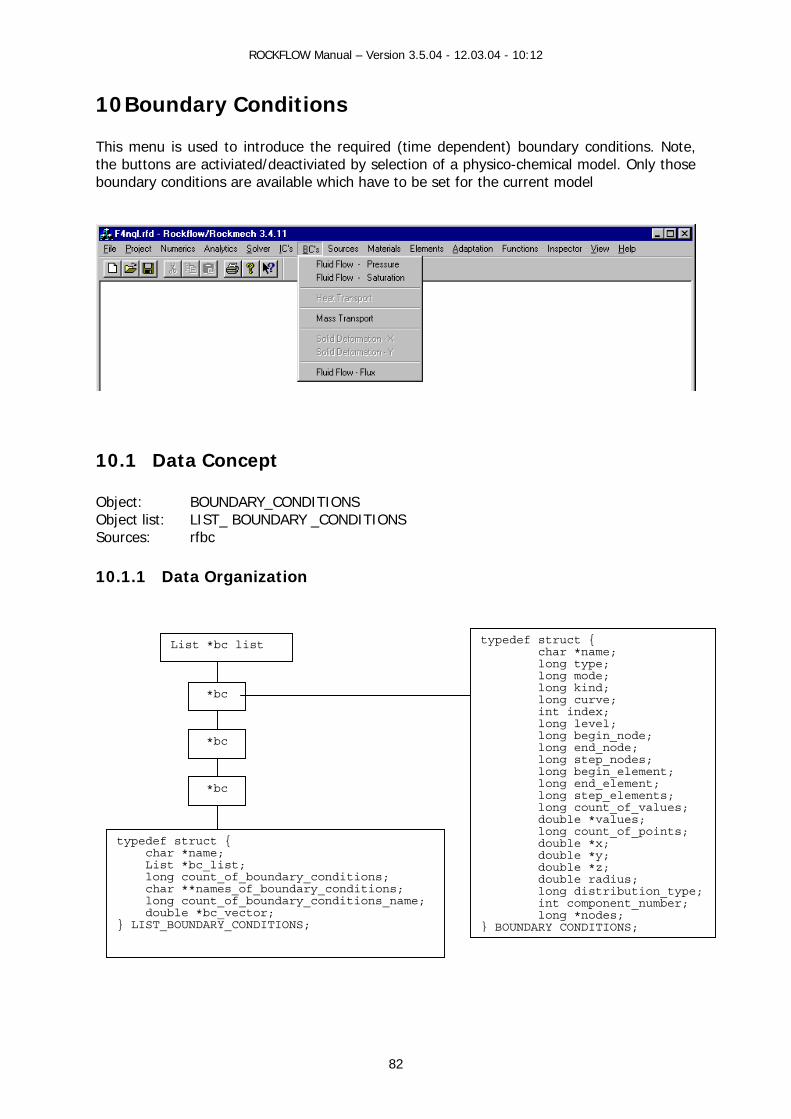
ROCKFLOW Manual – Version 3.5.04 - 12.03.04 - 10:12
82
0 Boundary Conditions
his menu is used to introduce the required (time dependent) boundary conditions. Note, ysico-chemical model. Only those
bounda et for the current model
1 Tthe buttons are activiated/deactiviated by selection of a ph
ry conditions are available which have to be s
10.1 Data Concept Object: BOUNDARY_CONDITIONS Object list: LIST_ BOUNDARY _CONDITIONS Sources: rfbc 10.1.1 Data Organization
typedef struct { char *name; List *bc_list; long count_of_boundary_conditions; char **names_of_boundary_conditions; long count_of_boundary_conditions_name; double *bc_vector; } LIST_BOUNDARY_CONDITIONS;
List *bc list
*bc
*bc
*bc
typedef struct { char *name; long type; long mode; long kind; long curve; int index; long level; long begin_node; long end_node; long step_nodes; long begin_element; long end_element; long step_elements; long count_of_values; double *values; long count_of_points; double *x; double *y; double *z; double radius; long distribution_type; int component_number; long *nodes; } BOUNDARY CONDITIONS;
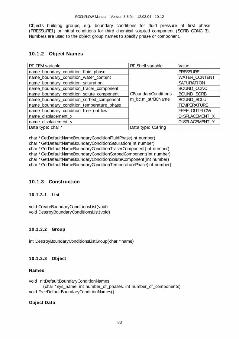
ROCKFLOW Manual – Version 3.5.04 - 12.03.04 - 10:12
83
y conditions for fluid pressure of first phase rd chemical sorpted component (SORB_CONC_3).
umbers are used to the object group names to specify phase or component.
0.1.2 RF-FEM F-Shell variable Value
Objects building groups, e.g. boundar(PRESSURE1) or initial conditions for thiN
1 Object Names
variable Rname_ PRESSURE boundary_condition_fluid_phase name_ WATER_CONTENT boundary_condition_water_content name_ SATURATION boundary_condition_saturation name_ BOUND_CONC boundary_condition_tracer_component name_ BOUND_SORB boundary_condition_solute_component name_ BOUND_SOLU boundary_condition_sorbed_component name_boundary_condition_temperature_phase TEMPERATURE name_boundary_condition_free_outflow FREE_OUTFLOW name_displacement_x DISPLACEMENT_X name_displacement_y
ndaryConditions bc.m_strBCName
DISPLACEMENT_Y
CBoum_
D ata type: CString ata type: char * D char *GetDefaultNameBoundaryConditionFchar *GetDefaultNameBoundaryConditionSchar *GetDefaultNameBoundaryCond nTchar *GetDefaultNameBoundaryConditionSchar *GetDefaultNameBoundaryConditionSchar *GetDefaultNameBoundaryCond nT 10.1.3 Construction 10.1.3.1 List void CreateBoundaryConditionsList(void) void DestroyBoundaryConditionsList( ) 10.1.3.2 Group int DestroyBo ditionsListGro p(ch 10.1.3.3 O Names void InitDefau ryConditionNames
har *sys_name, int number_ f_ph of_compovoid Fr efa ryConditionNa es( Object Data
luidPhase(int number) aturation(int number)
itio racerComponent(int number) orbedComponent(int number) oluteComponent(int number)
itio emperaturePhase(int number)
void
undaryCon u ar *name)
bject
ltBounda(ceeD
om
ases, int number_ nents) ultBounda )
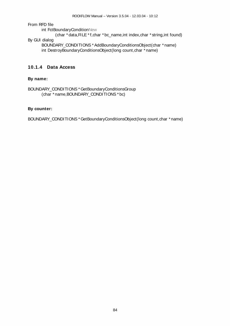
ROCKFLOW Manual – Version 3.5.04 - 12.03.04 - 10:12
84
F fileint Fct nditionNew
f,char *bc string,int found) By GUI dialog
DARY_CONDITIONS *AddBou e) t Des Conditions bje )
10.1.4 Da By name: BOUNDARY_C *GetBoundaryCo
(char *nam ONDITIO By counter: BOUNDARY_CONDITIONS *GetBoundaryCo ditionsObject(long count,char *name)
rom RFD BoundaryCo(char *data,FILE * _name,int index,char *
BOUNin
ndaryConditionsObject(char *namct(long count,char *nametroyBoundary O
ta Access
ONDITIONS nditionsGroup e,BOUNDARY_C NS *bc)
n

ROCKFLOW Manual – Version 3.5.04 - 12.03.04 - 10:12
85
10.2 Keyword Description The following ailable to specify boundary conditions for fluid flow, heat transport and nsport.
#BOUN ITIONS_PRESS#BOUN ONDITIONS_SATURATION #BOUN ITIONS_TEMPERATURE #BOUN ITIONS_CONCE TRATION #BOUN ONDITIONS_SORBE
OUN _CONDITIONS_S LUTOUN ONDITIONS_D PLACEMENT_X
#BOUN ITIONS_DISPLACEMENT_Y #BOUN ITIONS_FREE_OUTFLOW
By repeatedly use of the keywords, boundary conditions for correspoomponents are specified.
Values Meaning
keywords are av mass tra
DARY_COND URE DARY_CDARY_CONDDARY_COND NDARY_C D_CONCENTRATION
_CONCENTRATION #B#B
DARY OIS
EDARY_CDARY_CONDDARY_COND
nding phases and c Parameter RF Variable
N1 type 0 1
IndiIndividual
2 3
Linear distribution between two nodes byLinear distribution between two nodes by
4 5 6 7 8
Constant value at plain given by 3 points Linear distribution along polygon Constant value at plain given by polygon node numbersHydrostatic distribution at plain given by 3 points Constant value at plain given by polygon coordinates
9 10
16 17
vidual nodes by node number nodes by coordinates
coordinates node number
Bilinear distribution within rectangle by coordinates Bilinear distribution at plain given by coordinates
Bilinear distribution within rectangle by coordinates Hydrostatic distribution in rectangle / coordinates (eps)
11/0 12/5 13 14 15
Individual nodes by node number (eps) Linear distribution along polygon / coordinates (eps) Linear distribution along polygon / nodes (eps) Hydrostatic distribution in polygon / coordinates (eps) Hydrostatic distribution in polygon / nodes (eps)
N2 mode 0 1
Overwrite Superimpose
N3 curve int Curve number if N1=0 begin_node
values[0] Node number
Nodal value (AH) if N1=1 x[0] y[0] z[0]
radius[0] values[0]
Node coordinates Radius (>0.0) Nodal value (AH)
if N1=2 x[0] y[0] z[0] x[1] y[1] z[1] radius[0] values[0] values[1]
First node coordinates First nodal value „Radius“, epsilon Second node coordinates Second nodal value (RFE-Data not correct) (AH)
if N1=3 begin_node end_node step_nodes values[0] value[1]
First node Second node Increment First nodal value Second nodal value (RFE-Data has to be adjusted) (AH)

ROCKFLOW Manual – Version 3.5.04 - 12.03.04 - 10:12
86
if N1=4 x[0] y[0] z[0] x[1] y[1] z[1] x[2] y[2] z[2] radius[0] values[0]
First node coordinates Second node coordinates Third node coordinates „Radius“, epsilon Areal value (AH)
if N1=5 count_of_points nodes[count_of_points] values[count_of_points]
Number of polygon points Polygon nodes Nodal values (AH/CT)
if N1=6 count_of_points nodes[count_of_points] radius [0] value[0]
Number of surface polygon points Surface polygon nodes „Radius“, epsilon (does not work properly !!!) Areal value (RFE-Data not correct) (AH)
if N1=7 x[0] y[0] z[0] x[1] y[1] z[1] x[2] y[2] z[2] z[3] values[0]
First node coordinates Second node coordinates Third node coordinates Reference elevation Reference value (not yet tested) (AH)
if N1=8 count_of_points x[0] y[0] z[0] ... x[count_of_points-1] y[count_of_points-1] z[count_of_points-1] radius [0] values[0]
Number of polygon points Polygon node coordinates ... „Radius“, epsilon (does not work properly !!!) Value (RFE-Data not correct) (AH)
if N1=9 x[0] y[0] z[0] values[0] x[1] y[1] z[1] values[1] x[2] y[2] z[2] values[2] x[3] y[3] z[3] values[3]
Rectangle node coordinates Value ... (does not work properly !!!) (RK)
if N1=10 x[0] y[0] z[0] values[0] x[1] y[1] z[1] values[1] x[2] y[2] z[2] values[2] x[3] y[3] z[3] values[3]
Node coordinates Value ... (does not work properly !!!) (RK)
if N1=11 x[0] y[0] z[0] values[0] epsilon
(CT)
if N1=12 count_of_points x[count_of_points] y[count_of_points] z[count_of_points] values[count_of_points] epsilon
(CT)
if N1=13 count_of_points for(i<count_of_points) nodes[i] values[i] epsilon
(CT)
if N1=14 values[0] values[1] phase count_of_points x[count_of_points] y[count_of_points] z[count_of_points] epsilon
(not yet tested) (CT)
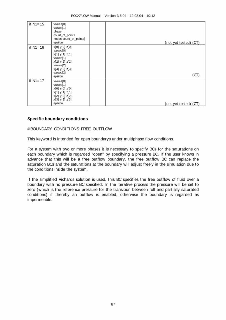
ROCKFLOW Manual – Version 3.5.04 - 12.03.04 - 10:12
87
if N1=15 values[0] values[1] phase count_of_points nodes[count_of_points] epsilon
(not yet tested) (CT)
if N1=16 x[0] y[0] z[0] values[0] x[1] y[1] z[1] values[1] x[2] y[2] z[2] values[2] x[3] y[3] z[3] values[3] epsilon
(CT)
if N1=17 values[0] values[1] x[0] y[0] z[0] x[1] y[1] z[1] x[2] y[2] z[2] x[3] y[3] z[3] epsilon
(not yet tested) (CT)
Specific boundary conditions #BOUNDARY_CONDITIONS_FREE_OUTFLOW This keyword is intended for open boundarys under multiphase flow conditions. For a system with two or more phases it is necessary to specify BCs for the saturations on each boundary which is regarded "open" by specifying a pressure BC. If the user knows in advance that this will be a free outflow boundary, the free outflow BC can replace the saturation BCs and the saturations at the boundary will adjust freely in the simulation due to the conditions inside the system. If the simplified Richards solution is used, this BC specifies the free outflow of fluid over a boundary with no pressure BC specified. In the iterative process the pressure will be set to zero (which is the reference pressure for the transition between full and partially saturated conditions) if thereby an outflow is enabled, otherwise the boundary is regarded as impermeable.
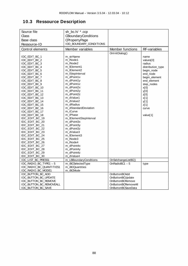
ROCKFLOW Manual – Version 3.5.04 - 12.03.04 - 10:12
88
10.3 Ressource Description
Source file Class Base class Ressource-ID
sh_bc.h/ *.ccp CBoundaryConditions CPropertyPage IDD_BOUNDARY_CONDITIONS
Control elements Member variables Member functions RF-variables OnInitDialog() IDC_EDIT_BC_1 m_strName name IDC_EDIT_BC_2 m_lNode1 values[0] IDC_EDIT_BC_3 m_lNode2 radius IDC_EDIT_BC_4 m_lElement1 distribution_type IDC_EDIT_BC_5 m_lElement2 begin_node IDC_EDIT_BC_6 m_lStepInterval end_node IDC_EDIT_BC_7 m_dPoint1x begin_element IDC_EDIT_BC_8 m_dPoint1y end_element IDC_EDIT_BC_9 m_dPoint1z step_nodes IDC_EDIT_BC_10 m_dPoint2x x[0] IDC_EDIT_BC_11 m_dPoint2y y[0] IDC_EDIT_BC_12 m_dPoint2z z[0] IDC_EDIT_BC_13 m_dValue1 x[1] IDC_EDIT_BC_14 m_dValue2 y[1] IDC_EDIT_BC_15 m_dRadius z[1] IDC_EDIT_BC_16 m_dStandardDeviation curve IDC_EDIT_BC_17 m_iCurve IDC_EDIT_BC_18 m_iPhase value[1] IDC_EDIT_BC_19 m_lElementStepInterval IDC_EDIT_BC_20 m_dPoint3x IDC_EDIT_BC_21 m_dPoint3y IDC_EDIT_BC_22 m_dPoint3z IDC_EDIT_BC_23 m_dValue3 IDC_EDIT_BC_24 m_lElement3 IDC_EDIT_BC_25 m_lNode3 IDC_EDIT_BC_26 m_lNode4 IDC_EDIT_BC_27 m_dPoint4x IDC_EDIT_BC_28 m_dPoint4y IDC_EDIT_BC_29 m_dPoint4z IDC_EDIT_BC_30 m_dValue4 IDC_LIST_BC_PRESS1 m_LBBoundaryConditions OnSelchangeListBC() IDC_RADIO_BC_TYPE1 – 5 m_iBCSelectedType OnRadioBC1 – 5 type IDC_RADIO_BC_QUANTITIES1 m_iBCQuantities IDC_RADIO_BC_MODE1 m_iBCMode IDC_BUTTON_BC_ADD OnButtonBCAdd IDC_BUTTON_BC_UPDATE OnButtonBCUpdate IDC_BUTTON_BC_REMOVE OnButtonBCRemove IDC_BUTTON_BC_REMOVEALL OnButtonBCRemoveAll IDC_BUTTON_BC_SAVE OnButtonBCSaveData

ROCKFLOW Manual – Version 3.5.04 - 12.03.04 - 10:12
89
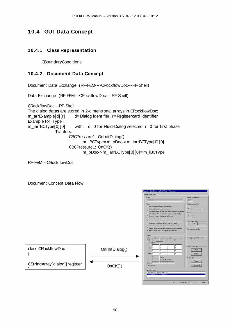
ROCKFLOW Manual – Version 3.5.04 - 12.03.04 - 10:12
10.4 GUI Data Concept
10.4.1 Class Representation
CBoundaryConditions
10.4.2 Document Data Concept Document Data Exchange (RF-FEM----CRockflowDoc---RF-Shell) Data Exchange (RF-FEM---CRockflowDoc--- RF-Shell) CRockflowDoc---RF-Shell: The dialog datas are stored in 2-dimensional arrays in CRockflowDoc: m_arrExample[d][r] d=Dialog identifier, r=Registercard identifier Example for ‘Type’: m_iarrBCType[0][0] with: d=0 for Fluid-Dialog selected, r=0 for first phase Tranfers: CBCPressure1::OnInitDialog() m_iBCType=m_pDoc->m_iarrBCType[0][0] CBCPressure1::OnOK() m_pDoc->m_iarrBCType[0][0]=m_iBCType RF-FEM---CRockflowDoc:
Document Concept Data Flow
OnOK())
OnInitDialog()
class CRockflowDoc { CStringArray[dialog][register]90
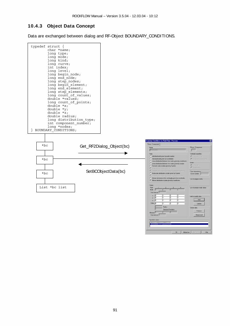
ROCKFLOW Manual – Version 3.5.04 - 12.03.04 - 10:12
10.4.3 Object Data Concept
Data are exchanged between dialog and RF-Object BOUNDARY_CONDITIONS.
typedef struct { char *name; long type; long mode; long kind; long curve; int index; long level; long begin_node; long end_node; long step_nodes; long begin_element; long end_element; long step_elements; long count_of_values; double *values; long count_of_points; double *x; double *y; double *z; double radius; long distribution_type; int component_number; long *nodes; } BOUNDARY_CONDITIONS;
91
*bc
*bc
*bc
List *bc list
SetBCObjectData(bc)
Get_RF2Dialog_Object(bc)
ROCKFLOW Manual – Version 3.5.04 - 12.03.04 - 10:12
92
10.5 GUI Functions
10.5.1 View Functions (CRockflowView) View functions connect the mainframe menu (pull-down menu) with the individual dialogs. void CRockflowView::OnBCFluidFlowSaturation() void CRockflowView::OnBCFluidFlowPressure() void CRockflowView::OnBCHeatTransport() void CRockflowView::OnBCMassTransport()
10.5.2 Document Data Exchange void WriteRF2Doc_BoundaryConditions(void) void WriteDoc2RF_BoundaryConditions(void)
10.5.3 Dialog Data Exchange void CBoundaryConditions::Get_RF2Dialog_ObjectGroup(void)
// Copies data of all BC objects named m_strBCName to protocol list box CString CBoundaryConditions::Get_RF2Dialog_Object(BOUNDARY_CONDITIONS *bc)
// Transfers BC object data to dialog data and freshens resource elements void CBoundaryConditions::SetBCObjectData(BOUNDARY_CONDITIONS *bc) // Transfers dialog data to BC object
10.5.4 Dialog Messages BOOL CBoundaryConditions::OnInitDialog()
// Transfers data from Objects/Document to the Dialog, fills the protocol list box void CBoundaryConditions::OnRadioBC1() - 5
// Activates resource elements for the selected BC object type void CBoundaryConditions::OnButtonBCAdd()
// Adds new BC object and build string for the protocol list box // Adds string in the protocol list box(Document concept only)
void CBoundaryConditions::OnButtonBCUpdate() // Updates BC object and protocol list box with dialog data
// Updates selected list box string with dialog data(Document concept) void CBoundaryConditions::OnButtonBCRemove()
// Removes selected BC object and corresponding protocol list box string // Removes selected protocol list box string(Document concept)
void CBoundaryConditions::OnButtonBCRemoveAll() // Removes all BC objects and empties protocol list box
// Removes all list box strings (Document concept) void CBoundaryConditions::OnSelchangeListBC()
// Transfers BC object data to dialog data and freshens resource elements void CBoundaryConditions::OnButtonBCSaveData() // Saves BC object data (only for string concept) void CBoundaryConditions::OnOK()

ROCKFLOW Manual – Version 3.5.04 - 12.03.04 - 10:12
93
// Saves BC object data // Transfers list box data to Arrays in Document (Document concept)
10.5.5 Functions for String Concept void CBoundaryConditions::OnInit_BCDialog() void CBoundaryConditions::OnAdd_BCDialog(int mode) void CBoundaryConditions::OnSel_BCDialog(void) void CBoundaryConditions::OnOK_Dialog(char *bc_name)
10.5.6 Auxiliary Functions void CBoundaryConditions::StatusDialogResourceElements(void) long CBoundaryConditions::GetBCType(void)
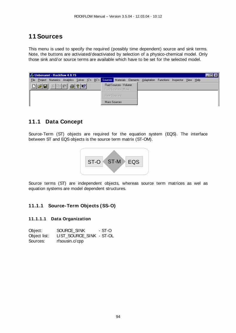
ROCKFLOW Manual – Version 3.5.04 - 12.03.04 - 10:12
94
11 Sources This menu is used to specify the required (possibly time dependent) source and sink terms. Note, the buttons are activiated/deactiviated by selection of a physico-chemical model. Only those sink and/or source terms are available which have to be set for the selected model.
11.1 Data Concept Source-Term (ST) objects are required for the equation system (EQS). The interface between ST and EQS objects is the source term matrix (ST-OM).
Source terms (ST) are independent objects, whereas source term matrices as wel as equation systems are model dependent structures.
11.1.1 Source-Term Objects (SS-O) 11.1.1.1 Data Organization Object: SOURCE_SINK - ST-O Object list: LIST_SOURCE_SINK - ST-OL Sources: rfsousin.c/cpp
ST-O EQSST-M
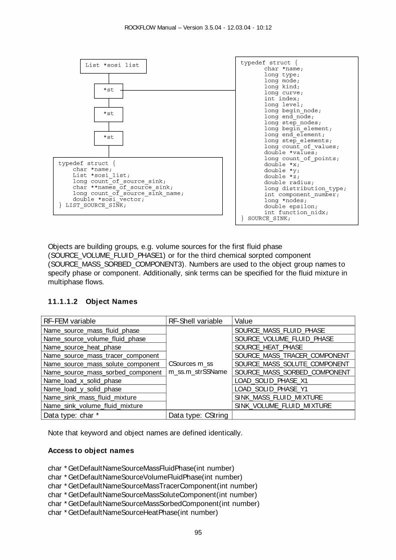
ROCKFLOW Manual – Version 3.5.04 - 12.03.04 - 10:12
95
Objects are building groups, e.g. volume sources for the first fluid phase (SOURCE_VOLUME_FLUID_PHASE1) or for the third chemical sorpted component (SOURCE_MASS_SORBED_COMPONENT3). Numbers are used to the object group names to specify phase or component. Additionally, sink terms can be specified for the fluid mixture in multiphase flows. 11.1.1.2 Object Names
RF-FEM variable RF-Shell variable Value Name_source_mass_fluid_phase SOURCE_MASS_FLUID_PHASE Name_source_volume_fluid_phase SOURCE_VOLUME_FLUID_PHASE Name_source_heat_phase SOURCE_HEAT_PHASE Name_source_mass_tracer_component SOURCE_MASS_TRACER_COMPONENT Name_source_mass_solute_component SOURCE_MASS_SOLUTE_COMPONENT Name_source_mass_sorbed_component SOURCE_MASS_SORBED_COMPONENT Name_load_x_solid_phase LOAD_SOLID_PHASE_X1 Name_load_y_solid_phase LOAD_SOLID_PHASE_Y1 Name_sink_mass_fluid_mixture SINK_MASS_FLUID_MIXTURE Name_sink_volume_fluid_mixture
CSources m_ss m_ss.m_strSSName
SINK_VOLUME_FLUID_MIXTURE Data type: char * Data type: CString
Note that keyword and object names are defined identically. Access to object names char *GetDefaultNameSourceMassFluidPhase(int number) char *GetDefaultNameSourceVolumeFluidPhase(int number) char *GetDefaultNameSourceMassTracerComponent(int number) char *GetDefaultNameSourceMassSoluteComponent(int number) char *GetDefaultNameSourceMassSorbedComponent(int number) char *GetDefaultNameSourceHeatPhase(int number)
typedef struct { char *name; List *sosi_list; long count_of_source_sink; char **names_of_source_sink; long count_of_source_sink_name; double *sosi_vector; } LIST_SOURCE_SINK;
typedef struct { char *name; long type; long mode; long kind; long curve; int index; long level; long begin_node; long end_node; long step_nodes; long begin_element; long end_element; long step_elements; long count_of_values; double *values; long count_of_points; double *x; double *y; double *z; double radius; long distribution_type; int component_number; long *nodes;
double epsilon; int function_nidx;
} SOURCE_SINK;
List *sosi list
*st
*st
*st
ROCKFLOW Manual – Version 3.5.04 - 12.03.04 - 10:12
96
11.1.1.3 Construction List void CreateSourceSinkList(void) void DestroySourceSinkList(void) Group int DestroySourceSinkListGroup(char *name) Object From RFD file
int FctSourcePhaseNew ( ... char *name ... ) int FctSourceMixtureNew ( ... char *name ...)
By GUI dialog void CSources::OnButtonSSAdd()
ss = AddSourceSinkObject(ss_name); void CSources::OnButtonSSRemove()
DestroySourceSinkObject(nSel,ss_name);
Object names void InitDefaultSourceSinkNames (..., int number_of_phases, int number_of_components) void FreeDefaultSourceSinkNames() 11.1.1.4 Data Access void CSources::Get_RF2Dialog_ObjectGroup(void) CString CSources::Get_RF2Dialog_Object(SOURCE_SINK *ss)
SOURCE_SINK *GetSourceSinkGroup(char *name,SOURCE_SINK *ss) SOURCE_SINK *GetSourceSinkObject(long count, char *name)
void CSources::Set_Dialog2RF_Object(SOURCE_SINK *ss)
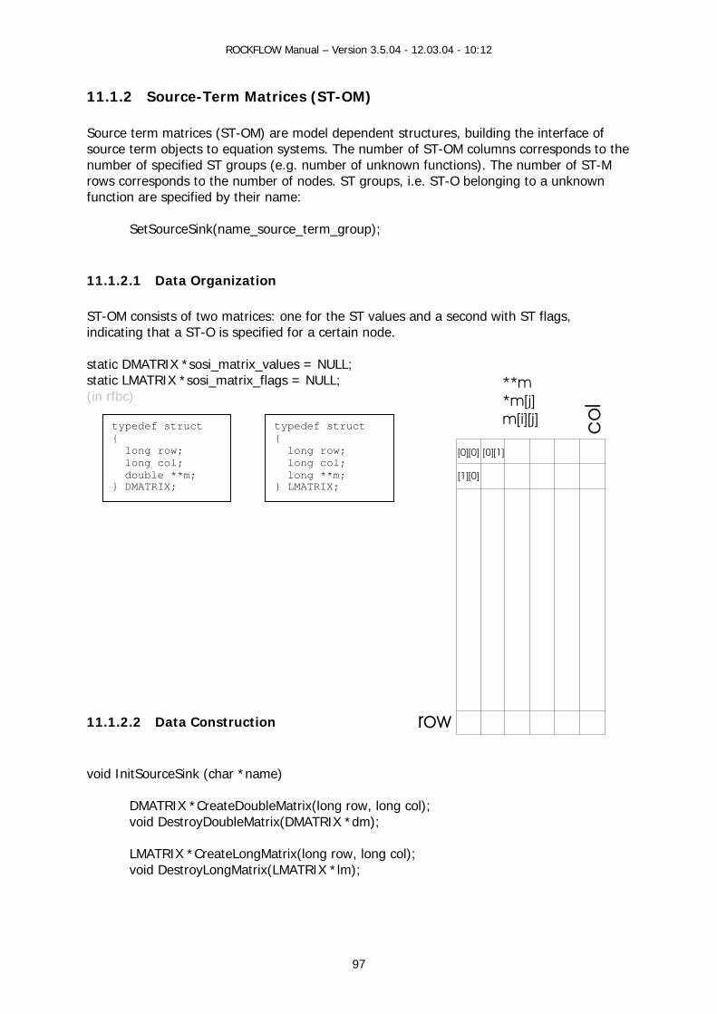
ROCKFLOW Manual – Version 3.5.04 - 12.03.04 - 10:12
97
row
**m*m[j]m[i][j]
[0][0]
[1][0]
[0][1]
co
l
11.1.2 Source-Term Matrices (ST-OM) Source term matrices (ST-OM) are model dependent structures, building the interface of source term objects to equation systems. The number of ST-OM columns corresponds to the number of specified ST groups (e.g. number of unknown functions). The number of ST-M rows corresponds to the number of nodes. ST groups, i.e. ST-O belonging to a unknown function are specified by their name:
SetSourceSink(name_source_term_group); 11.1.2.1 Data Organization ST-OM consists of two matrices: one for the ST values and a second with ST flags, indicating that a ST-O is specified for a certain node. static DMATRIX *sosi_matrix_values = NULL; static LMATRIX *sosi_matrix_flags = NULL; (in rfbc)
11.1.2.2 Data Construction void InitSourceSink (char *name)
DMATRIX *CreateDoubleMatrix(long row, long col); void DestroyDoubleMatrix(DMATRIX *dm); LMATRIX *CreateLongMatrix(long row, long col); void DestroyLongMatrix(LMATRIX *lm);
typedef struct { long row; long col; double **m; } DMATRIX;
typedef struct { long row; long col; long **m; } LMATRIX;

ROCKFLOW Manual – Version 3.5.04 - 12.03.04 - 10:12
98
11.2 Object Communication
11.2.1 ST-ObjectList (ST-OL) <---> ST-ObjectMatrix (ST-OM) The function
ExecuteAllSourceSink (void) copies all ST objects to the ST matrices.
11.2.2 The function
incorpora em (EQS).
u1 u2 u3 unu
SS-Mnumber of unknowns
num
be
r of n
od
es
IncorporateSS (ss_name)LES
les->b
ss_n
am
e
SS
NOD
ExecuteSSMethod
LMATRIX *ss_matrix_flags DMATRIX *ss_matrix_values
u1 u2 u3 unu
number of unknowns
num
be
r of n
od
es
ss_n
am
e
u1 u2 u3 unu
number of unknowns
num
be
r of n
od
es
ss_n
am
eSS-ObjectMatrix (ST-OM) <---> LES
s int IncorporateSourceSink ( ... ); int IncorporateSourceSinkEx ( ... ); int IncorporateSourceSinkEx2 ( ... ); int IncorporateSourceSinkVec ( ... );
te the specified ST objects into the right-hand-side of the equation syst
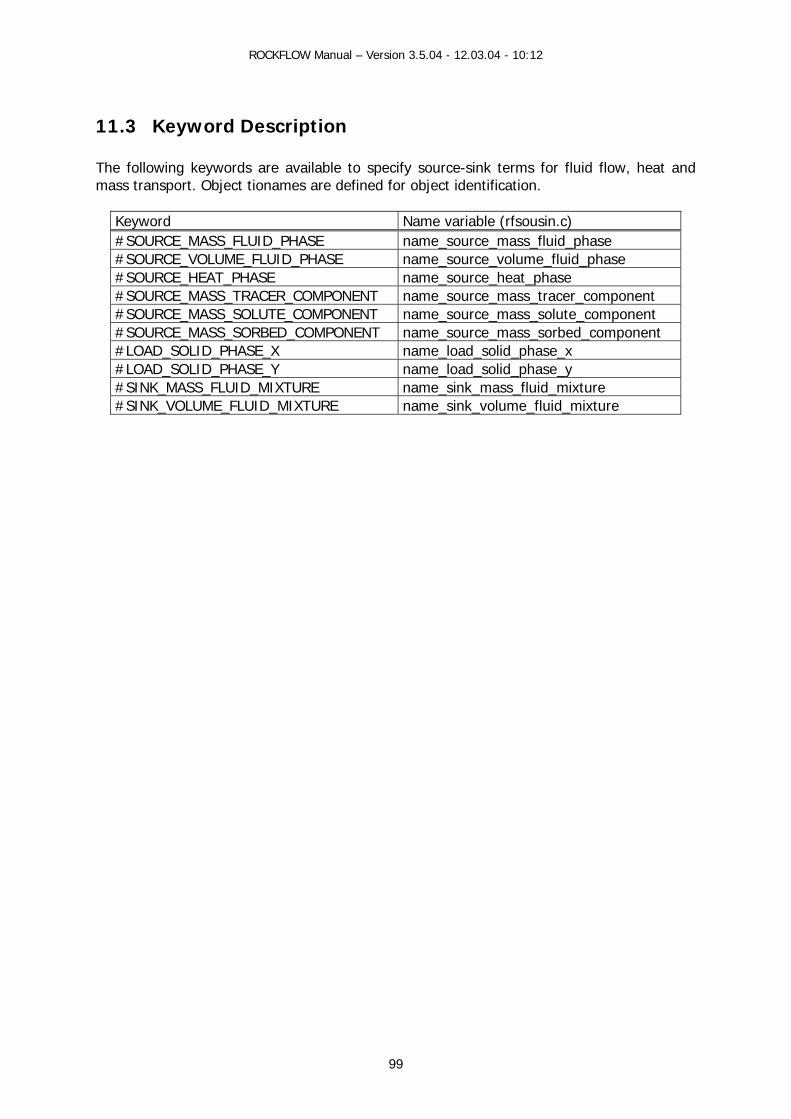
ROCKFLOW Manual – Version 3.5.04 - 12.03.04 - 10:12
99
11.3 Keyword Description The following keywords are available to specify source-sink terms for fluid flow, heat and mass transport. Object tionames are defined for object identification.
Keyword Name variable (rfsousin.c) #SOURCE_MASS_FLUID_PHASE name_source_mass_fluid_phase #SOURCE_VOLUME_FLUID_PHASE name_source_volume_fluid_phase #SOURCE_HEAT_PHASE name_source_heat_phase #SOURCE_MASS_TRACER_COMPONENT name_source_mass_tracer_component #SOURCE_MASS_SOLUTE_COMPONENT name_source_mass_solute_component #SOURCE_MASS_SORBED_COMPONENT name_source_mass_sorbed_component #LOAD_SOLID_PHASE_X name_load_solid_phase_x #LOAD_SOLID_PHASE_Y name_load_solid_phase_y #SINK_MASS_FLUID_MIXTURE name_sink_mass_fluid_mixture #SINK_VOLUME_FLUID_MIXTURE name_sink_volume_fluid_mixture

ROCKFLOW Manual – Version 3.5.04 - 12.03.04 - 10:12
100
By repeatedly use of the keywords, source terms for corresponding phases and components are specified. Para-meter
Variables Values Meaning
N1 type 0 1 2 3 4 6 7 8 9 10
Nodal source given by node number Nodal source given by node coordinates Nodal sources along line defined by two nodes (coordinates) Flux distributed along line defined by two nodes (coordinates)Nodal sources at plain surface given by 3 nodes (coordinates) Nodal sources at a polygon given by node coordinates (eps) Nodal sources at a polygon given by node numbers (eps) Nodal source given by node coordinates (eps) Distributed nodal source given by coordinates (eps) Transfer function by nodal sources
AH AH AH AH AH CT CT CT CT OK
N2 mode 0 1
Overwrite Superimpose
N3 curve long Number of time curve if N1=0 begin_node
values[0] Node number
Nodal value
if N1=1 x[0] y[0] z[0] values[0]
Node coordinates Nodal value
if N1=2 x[0] y[0] z[0] x[1] y[1] z[1] values[0]
First node coordinates Second node coordinates Nodal value (to all nodes along this line)
if N1=3 x[0] y[0] z[0] x[1] y[1] z[1] values[0]
First node coordinates Second node coordinates Flux (distributed to all nodes along this line)
if N1=4 x[0] y[0] z[0] x[1] y[1] z[1] x[2] y[2] z[2] values[0]
First node coordinates Second node coordinates Third node coordinates Nodal value
if N1=6 count_of_points x[i] y[i] z[i] epsilon values[0]
Number of nodes Node coordinates Geometric tolerance to catch nodes Value (to be integrated over polygone)
if N1=7 count_of_points nodes[i] epsilon values[0]
Number of nodes Node numbers Geometric tolerance to catch nodes Value (to be integrated over polygone)
if N1=8 x[0] y[0] z[0] epsilon values[0]
Node coordinates Geometric tolerance to catch nodes Nodal value
if N1=9 x[0] y[0] z[0] epsilon values[1] values[0]
Node coordinates Geometric tolerance to catch nodes Distribution function Nodal value
if N1=10 values[0] Transfer coefficient
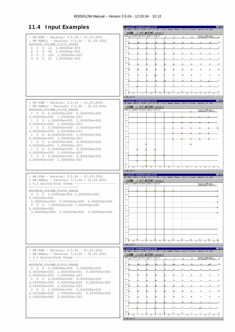
ROCKFLOW Manual – Version 3.5.04 - 12.03.04 - 10:12
101
11.4 Input Examples
11.5 ; RF-FEM - Version: 3.5.04 - 01.03.2001 ; RF-SHELL - Version: 3.5.04 - 01.03.2001 #SOURCE_VOLUME_FLUID_PHASE 0 0 0 12 1.000000e-003 0 0 0 36 1.000000e-003 0 0 0 120 1.000000e-003 0 0 0 31 1.000000e-003
; RF-FEM - Version: 3.5.04 - 01.03.2001 ; RF-SHELL - Version: 3.5.04 - 01.03.2001 ; 6.2 Source/Sink Terms ------------------------------------------------ #SOURCE_VOLUME_FLUID_PHASE 2 0 0 0.000000e+000 0.000000e+000 0.000000e+000 1.000000e+001 0.000000e+000 0.000000e+000 1.000000e-003 2 0 0 0.000000e+000 9.000000e+000 0.000000e+000 5.000000e+000 9.000000e+000 0.000000e+000 2.000000e-003 2 0 0 1.000000e+001 5.000000e+000 0.000000e+000 1.000000e+001 9.000000e+000 0.000000e+000 3.000000e-003
; RF-FEM - Version: 3.5.04 - 01.03.2001 ; RF-SHELL - Version: 3.5.04 - 01.03.2001 ; 6.2 Source/Sink Terms ------------------------------------------------ #SOURCE_VOLUME_FLUID_PHASE 9 0 0 2.000000e+000 2.000000e+000 0.000000e+000 2.000000e+000 0.000000e+000 0.000000e+000 9 0 0 7.000000e+000 7.000000e+000 0.000000e+000 3.000000e+000 0.000000e+000 0.000000e+000
; RF-FEM - Version: 3.5.04 - 01.03.2001 ; RF-SHELL - Version: 3.5.04 - 01.03.2001 #SOURCE_VOLUME_FLUID_PHASE 1 0 0 0.000000e+000 0.000000e+000 0.000000e+000 1.000000e-003 1 0 0 1.000000e+000 1.000000e+000 0.000000e+000 1.000000e-003 1 0 0 3.000000e+000 1.000000e+000 0.000000e+000 1.000000e-003 1 0 0 8.000000e+000 1.000000e+000 0.000000e+000 1.000000e-003 1 0 0 2.000000e+000 9.000000e+000 0.000000e+000 1.000000e-003 1 0 0 5.000000e+000 9.000000e+000 0.000000e+000 1.000000e-003 1 0 0 9.000000e+000 9.000000e+000 0.000000e+000 1.000000e-003
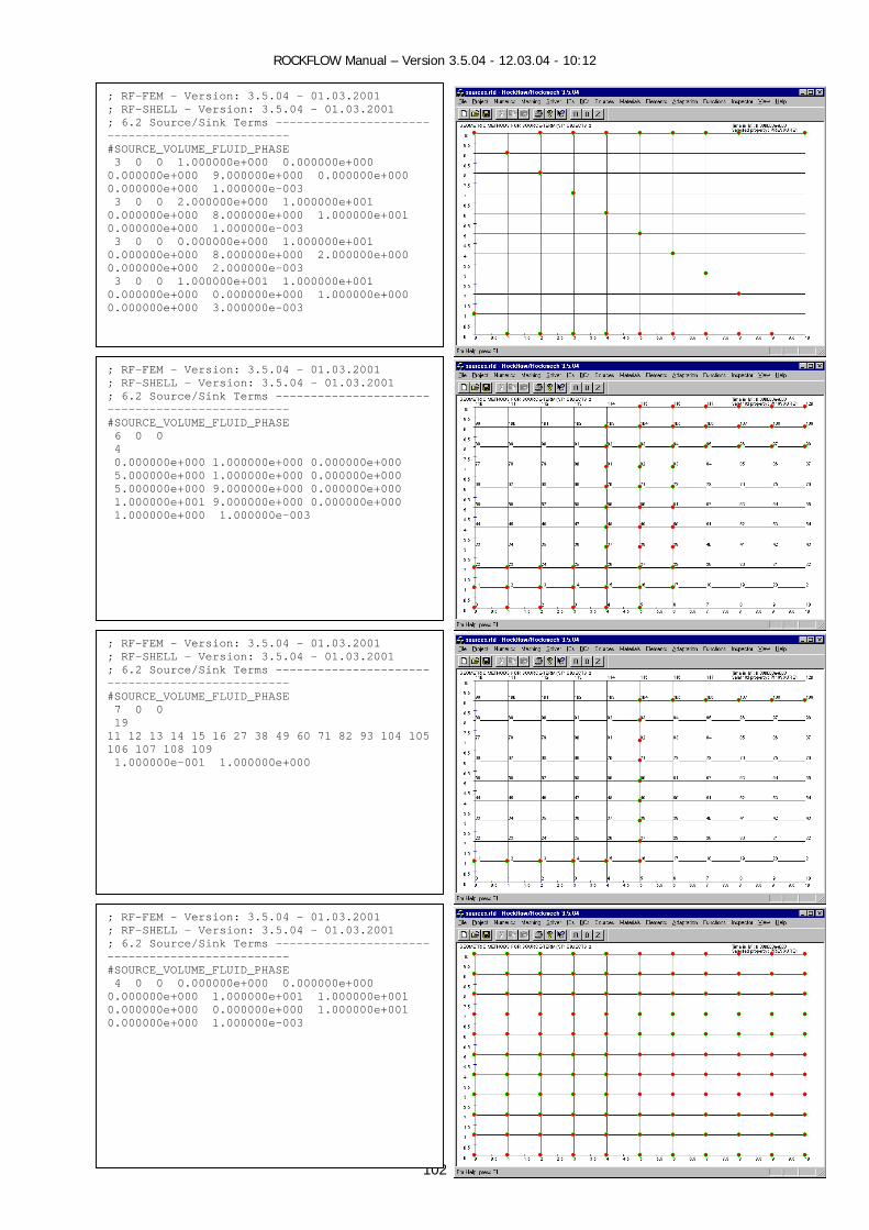
ROCKFLOW Manual – Version 3.5.04 - 12.03.04 - 10:12
102
; RF-FEM - Version: 3.5.04 - 01.03.2001 ; RF-SHELL - Version: 3.5.04 - 01.03.2001 ; 6.2 Source/Sink Terms ------------------------------------------------ #SOURCE_VOLUME_FLUID_PHASE 7 0 0 19 11 12 13 14 15 16 27 38 49 60 71 82 93 104 105 106 107 108 109 1.000000e-001 1.000000e+000
; RF-FEM - Version: 3.5.04 - 01.03.2001 ; RF-SHELL - Version: 3.5.04 - 01.03.2001 ; 6.2 Source/Sink Terms ------------------------------------------------ #SOURCE_VOLUME_FLUID_PHASE 3 0 0 1.000000e+000 0.000000e+000 0.000000e+000 9.000000e+000 0.000000e+000 0.000000e+000 1.000000e-003 3 0 0 2.000000e+000 1.000000e+001 0.000000e+000 8.000000e+000 1.000000e+001 0.000000e+000 1.000000e-003 3 0 0 0.000000e+000 1.000000e+001 0.000000e+000 8.000000e+000 2.000000e+000 0.000000e+000 2.000000e-003 3 0 0 1.000000e+001 1.000000e+001 0.000000e+000 0.000000e+000 1.000000e+000 0.000000e+000 3.000000e-003
; RF-FEM - Version: 3.5.04 - 01.03.2001 ; RF-SHELL - Version: 3.5.04 - 01.03.2001 ; 6.2 Source/Sink Terms ------------------------------------------------ #SOURCE_VOLUME_FLUID_PHASE 4 0 0 0.000000e+000 0.000000e+000 0.000000e+000 1.000000e+001 1.000000e+001 0.000000e+000 0.000000e+000 1.000000e+001 0.000000e+000 1.000000e-003
; RF-FEM - Version: 3.5.04 - 01.03.2001 ; RF-SHELL - Version: 3.5.04 - 01.03.2001 ; 6.2 Source/Sink Terms ------------------------------------------------ #SOURCE_VOLUME_FLUID_PHASE 6 0 0 4 0.000000e+000 1.000000e+000 0.000000e+000 5.000000e+000 1.000000e+000 0.000000e+000 5.000000e+000 9.000000e+000 0.000000e+000 1.000000e+001 9.000000e+000 0.000000e+000 1.000000e+000 1.000000e-003

ROCKFLOW Manual – Version 3.5.04 - 12.03.04 - 10:12
103
; RF-FEM - Version: 3.5.04 - 01.03.2001 ; RF-SHELL - Version: 3.5.04 - 01.03.2001 ; 6.2 Source/Sink Terms ------------------------------------------------ #SOURCE_VOLUME_FLUID_PHASE 10 0 0 1.234500e-005
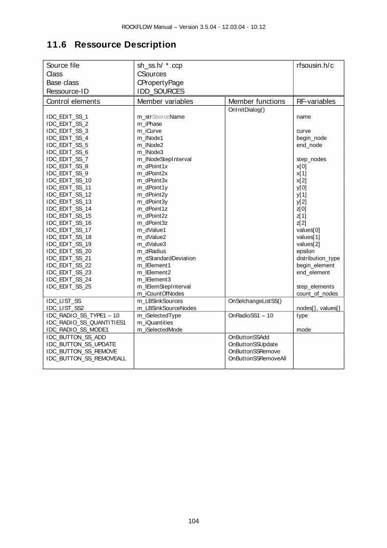
ROCKFLOW Manual – Version 3.5.04 - 12.03.04 - 10:12
104
11.6 Ressource Description Source file Class Base class Ressource-ID
sh_ss.h/ *.ccp CSources CPropertyPage IDD_SOURCES
rfsousin.h/c
Control elements Member variables Member functions RF-variables OnInitDialog() IDC_EDIT_SS_1 m_strSourceName name IDC_EDIT_SS_2 m_iPhase IDC_EDIT_SS_3 m_iCurve curve IDC_EDIT_SS_4 m_lNode1 begin_node IDC_EDIT_SS_5 m_lNode2 end_node IDC_EDIT_SS_6 m_lNode3 IDC_EDIT_SS_7 m_lNodeStepInterval step_nodes IDC_EDIT_SS_8 m_dPoint1x x[0] IDC_EDIT_SS_9 m_dPoint2x x[1] IDC_EDIT_SS_10 m_dPoint3x x[2] IDC_EDIT_SS_11 m_dPoint1y y[0] IDC_EDIT_SS_12 m_dPoint2y y[1] IDC_EDIT_SS_13 m_dPoint3y y[2] IDC_EDIT_SS_14 m_dPoint1z z[0] IDC_EDIT_SS_15 m_dPoint2z z[1] IDC_EDIT_SS_16 m_dPoint3z z[2] IDC_EDIT_SS_17 m_dValue1 values[0] IDC_EDIT_SS_18 m_dValue2 values[1] IDC_EDIT_SS_19 m_dValue3 values[2] IDC_EDIT_SS_20 m_dRadius epsilon IDC_EDIT_SS_21 m_dStandardDeviation distribution_type IDC_EDIT_SS_22 m_lElement1 begin_element IDC_EDIT_SS_23 m_lElement2 end_element IDC_EDIT_SS_24 m_lElement3 IDC_EDIT_SS_25 m_lElemStepInterval step_elements m_iCountOfNodes count_of_nodes IDC_LIST_SS m_LBSinkSources OnSelchangeListSS() IDC_LIST_SS2 m_LBSinkSourceNodes nodes[], values[]IDC_RADIO_SS_TYPE1 – 10 m_iSelectedType OnRadioSS1 – 10 type IDC_RADIO_SS_QUANTITIES1 m_iQuantities IDC_RADIO_SS_MODE1 m_iSelectedMode mode IDC_BUTTON_SS_ADD OnButtonSSAdd IDC_BUTTON_SS_UPDATE OnButtonSSUpdate IDC_BUTTON_SS_REMOVE OnButtonSSRemove IDC_BUTTON_SS_REMOVEALL OnButtonSSRemoveAll

ROCKFLOW Manual – Version 3.5.04 - 12.03.04 - 10:12
105
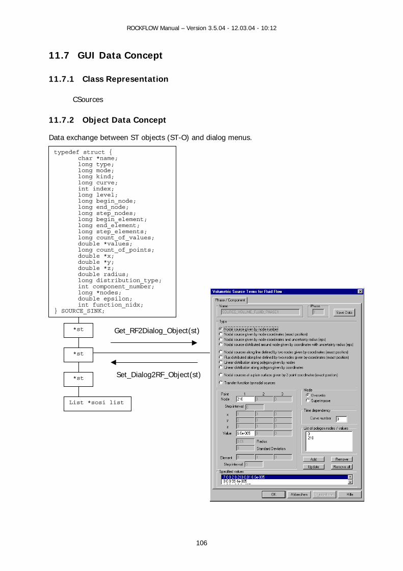
ROCKFLOW Manual – Version 3.5.04 - 12.03.04 - 10:12
11.7 GUI Data Concept
11.7.1 Class Representation
CSources
11.7.2 Object Data Concept
Data exchange between ST objects (ST-O) and dialog menus.
typedef struct { char *name; long type; long mode; long kind; long curve; int index; long level; long begin_node; long end_node; long step_nodes; long begin_element; long end_element; long step_elements; long count_of_values; double *values; long count_of_points; double *x; double *y; double *z; double radius; long distribution_type; int component_number; long *nodes;
double epsilon; int function_nidx;
} SOURCE_SINK;
*st
*st
*st
List *sosi l
Get_RF2Dialog_Object(st)
Set_Dialog2RF_Object(st)
106
ist

ROCKFLOW Manual – Version 3.5.04 - 12.03.04 - 10:12
107
11.7.3 Document Data Concept Document Data Exchange (RF-FEM----CRockflowDoc---RF-Shell) Data Exchange (RF-FEM---CRockflowDoc--- RF-Shell) CRockflowDoc---RF-Shell: The dialog datas are stored in 2-dimensional arrays in CRockflowDoc: m_arrExample[d][r] d=Dialog identifier, r=Registercard identifier Example for ‘Type’: m_iarrBCType[0][0] with: d=0 for Fluid-Dialog selected, r=0 for first phase Tranfers: CBCPressure1::OnInitDialog() m_iBCType=m_pDoc->m_iarrBCType[0][0] CBCPressure1::OnOK() m_pDoc->m_iarrBCType[0][0]=m_iBCType RF-FEM---CRockflowDoc:
Document Concept Data Flow
class CRockflowDoc { CStringArray[dialog][register] }
OnOK())
OnInitDialog()
ROCKFLOW Manual – Version 3.5.04 - 12.03.04 - 10:12
108
11.8 GUI Functions
11.8.1 View Functions (CRockflowView) View functions connect the mainframe menu (pull-down menus) with the individual dialogs. void CRockflowView::OnSSFluidFlowVolume() void CRockflowView::OnSSFluidFlowMass() void CRockflowView::OnSSHeatTransport() void CRockflowView::OnSSMassTransport()
11.8.2 Document Data Exchange void WriteRF2Doc_Sources(void) void WriteDoc2RF_Sources(void)
11.8.3 Dialog Data Exchange void CSources::Get_RF2Dialog_ObjectGroup(void)
// Copies data of all SS objects named m_strSSName to protocol list box CString CSources::Get_RF2Dialog_Object(SOURCES_SINK *ss)
// Transfers SS object data to dialog data and freshens resource elements void CSources::Set_Dialog2RF_Object(SOURCES_SINK *ss) // Transfers dialog data to SS object
11.8.4 Dialog Messages BOOL CSources::OnInitDialog()
// Transfers data from Objects/Document to the Dialog, fills the protocol list box void CSources::OnRadio1() - 5
// Activates resource elements for the selected SS object type void CSources::OnButtonAdd()
// Adds new SS object and build string for the protocol list box // Adds string in the protocol list box(Document concept only)
void CSources::OnButtonUpdate() // Updates SS object and protocol list box with dialog data
// Updates selected list box string with dialog data(Document concept) void CSources::OnButtonRemove()
// Removes selected SS object and corresponding protocol list box string // Removes selected protocol list box string(Document concept)
void CSources::OnButtonRemoveAll() // Removes all SS objects and empties protocol list box
// Removes all list box strings (Document concept) void CSources::OnSelchangeList()
// Transfers SS object data to dialog data and freshens resource elements void CSources::OnButtonSaveData() // Saves SS object data (only for string concept)
ROCKFLOW Manual – Version 3.5.04 - 12.03.04 - 10:12
109
void CSources::OnOK() // Saves SS object data
// Transfers list box data to Arrays in Document (Document concept)
11.8.5 Functions for String Concept void CSources::OnInit_Dialog() void CSources::OnAdd_Dialog(int mode) void CSources::OnSel_Dialog(void) void CSources::OnOK_Dialog(char *name)
11.8.6 Auxiliary Functions void CSources::StatusDialogResourceElements(int selType) long CSources::GetType(void)
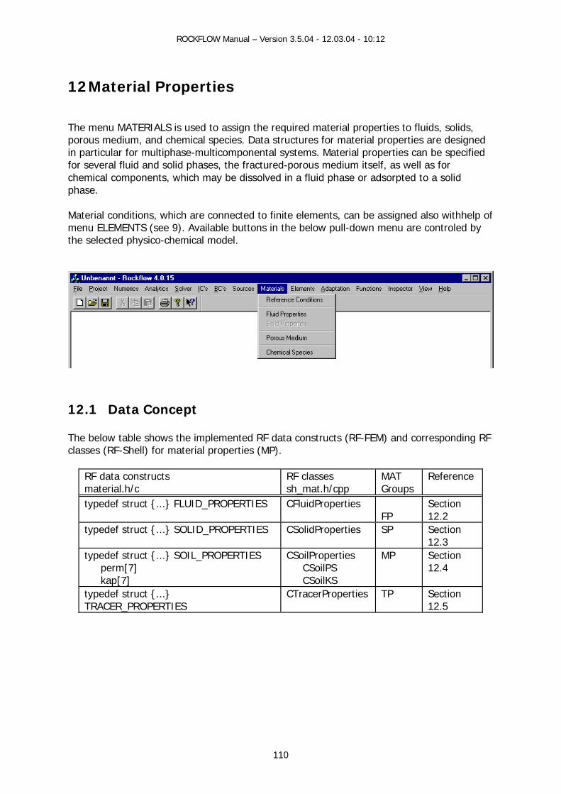
ROCKFLOW Manual – Version 3.5.04 - 12.03.04 - 10:12
110
12 Material Properties The menu MATERIALS is used to assign the required material properties to fluids, solids, porous medium, and chemical species. Data structures for material properties are designed in particular for multiphase-multicomponental systems. Material properties can be specified for several fluid and solid phases, the fractured-porous medium itself, as well as for chemical components, which may be dissolved in a fluid phase or adsorpted to a solid phase. Material conditions, which are connected to finite elements, can be assigned also withhelp of menu ELEMENTS (see 9). Available buttons in the below pull-down menu are controled by the selected physico-chemical model.
12.1 Data Concept The below table shows the implemented RF data constructs (RF-FEM) and corresponding RF classes (RF-Shell) for material properties (MP).
RF data constructs material.h/c
RF classes sh_mat.h/cpp
MAT Groups
Reference
typedef struct {...} FLUID_PROPERTIES CFluidProperties FP
Section 12.2
typedef struct {...} SOLID_PROPERTIES CSolidProperties SP Section 12.3
typedef struct {...} SOIL_PROPERTIES perm[7] kap[7]
CSoilProperties CSoilPS CSoilKS
MP Section 12.4
typedef struct {...} TRACER_PROPERTIES
CTracerProperties TP Section 12.5

ROCKFLOW Manual – Version 3.5.04 - 12.03.04 - 10:12
111
12.1.1 Material Properties List All the different material properties objects (FP,SP,MP,TP) are organized in one list - List *mp_list.
*mat list
typedef struct { char *name; List name List *mp_list; List of objects long count_of_material_properties; Number of MAT groups char **names_of_material_properties; Names of MAT groups long count_of_material_properties_name; Number of MAT group names} LIST_MATERIAL_PROPERTIES;
*mat
typedef struct { long type; char *name; int density_model; double rho_0; double drho_dp; double drho_dT; double drho_dC; int viscosity_model; double my_0; double dmy_dp; double dmy_dT; double dmy_dC; int curve; double Z; double heat_capacity; double heat_conductivity;} FLUID_PROPERTIES;
typedef struct { long type; char *name; /* Geometry */ int dimension; double area; double porosity; double tortuosity; double specific_area; /* Fluid flow */ int nonlinearflowelement; double nonlinearflowparameter; double storativity; int permeabilitymodel; double k[9]; double perm[7]; double kap[7]; /* Mass transport */ double massdispL; double massdispT; /* Heat transport */ double heatdispL; double heatdispT; /* Solid properties */ int heatconductivitymodel; double heatconductivitytensor[3]; double densityrock; double heatcapacityrock; } SOIL_PROPERTIES;
typedef struct { long type; char *name; /* Transport */ double molecular_diffusion; /* Chemical reactions */ double decay_rate; long isotherm; double partitioning coefficient; double sorption_k1; double sorption_k2; double nonequilibrium coefficient; /* Solution */ double solubility; double dissolution_rate; } TRACER_PROPERTIES;
typedef struct { } SOLID_PROPERTIES;
*mat
*mat
*mat

ROCKFLOW Manual – Version 3.5.04 - 12.03.04 - 10:12
Construction/Destruction CreateMaterialPropertiesList()
create_material_properties_list (name_material_properties_list) declare_material_properties_name (name_material_properties_list)
DestroyMaterialPropertiesList() char * name_material_properties_list = AMATERIAL_PROPERTIESA
12.1.2 Material Properties Groups Material properties are divided into four groups. Identification of a group is either by group name or by group type (MP_TYPE).
Groups Group Names Group Type Fluid phase properties
name_fluid_properties = FLUID_PROPERTIES
FLUID_PROP = 2
Solid phase properties
name_solid_properties = SOLID_PROPERTIES
SOLID_PROP = 0
Porous medium properties
name_soil_properties = SOIL_PROPERTIES
SOIL_PROP = 1
Component properties
name_tracer_properties = TRACER_PROPERTIES
TRACER_PROP = 3
typedef enum {SOLID_PROP = 0, SOIL_PROP, FLUID_PROP, TRACER_PROP} MP_TYPE; Each material property group can consist of several members, e.g. several fluid phases, locally varying soil or solid properties and chemical properties of different species in multicomponent systems.
112
ROCKFLOW Manual – Version 3.5.04 - 12.03.04 - 10:12
113
12.1.3 Material Properties Table Complex data structures as material properties can be handled conveniently in a list. On the other hand, access to data in a list is time consuming. For fast data access during FEM simulation we can get the data from a data container - the material properties table - which is in fact an multidimensional array:
table[n_fp][n_sp][n_mp][n_tp] n_fp - number of fluid properties n_sp - number of soild properties n_mp - number of porous medium properties n_tp - number of tracer properties
Construction/Destruction
mpt = create_material_properties_table(name, g, p, c); void destroy_material_properties_table(void *member);
Interface
construction void InitMaterialProperties(char *name, long g, long p, long c) destrucion void DestroyMaterialPropertiesList(void)
typedef struct { char *name; long count_of_groups; long count_of_solids; long count_of_soils; long count_of_phases; long count_of_components; SOLID_PROPERTIES **solid_properties_table; SOIL_PROPERTIES **soil_properties_table; FLUID_PROPERTIES **fluid_properties_table; TRACER_PROPERTIES **tracer_properties_table; long ***table;
} MATERIAL_PROPERTIES_TABLE;
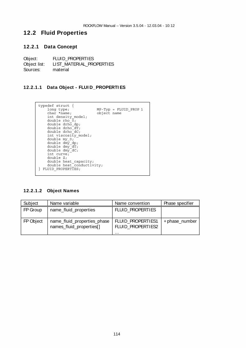
ROCKFLOW Manual – Version 3.5.04 - 12.03.04 - 10:12
114
12.2 Fluid Properties
12.2.1 Data Concept Object: FLUID_PROPERTIES Object list: LIST_MATERIAL_PROPERTIES Sources: material 12.2.1.1 Data Object - FLUID_PROPERTIES
12.2.1.2 Object Names Subject Name variable Name convention Phase specifier FP Group name_fluid_properties FLUID_PROPERTIES
FP Object name_fluid_properties_phase
names_fluid_properties[] FLUID_PROPERTIES1 FLUID_PROPERTIES2 ...
+phase_number
typedef struct { long type; MP-Typ = FLUID_PROP 1 char *name; object name int density_model; double rho_0; double drho_dp; double drho_dT; double drho_dC; int viscosity_model; double my_0; double dmy_dp; double dmy_dT; double dmy_dC; int curve; double Z; double heat_capacity; double heat_conductivity; } FLUID_PROPERTIES;
ROCKFLOW Manual – Version 3.5.04 - 12.03.04 - 10:12
115
12.2.1.3 Construction Fluid properties data can be created either from reading the RFD file or interactively by use of the fluid properties dialog. - from RFD file
FctFluidPropertiesNew ( char *data, int found, FILE *f ) destruction by list destruction
- by fluid properties dialog
CreateFluidPropertiesDefaultsNew(number_of_phases); 12.2.1.4 Data Access Access to FP objects is possible either from MAT list or from MAT table. - from MAT list by object name:
fp = get_fp_object (name_fluid_properties_phase,fp)
- from MAT table by phase number : fp = GetFluidProperties (phase)
Data access to individual FLUID_PROPERTIES We can use the standard data access functions within the MAT environment (#include "material.h")
get_fp_property(fp) set_fp_property(fp,value)
12.2.1.5 Methods Fluid properties depends on the thermodynamic state variables of the specific model. Therefore, the parameter list must be variable.
double CalcFluidDensity (int phase, ...); double CalcFluidViscosity(int phase, ...);
Function prototypes are defined for the model interface, i.e, within the MODEL environment.
DoubleFuncILDDDD GetFluidViscosity; DoubleFuncILDDDD GetFluidDensity; DoubleFuncILD GetNodeFluidDensity; DoubleFuncILD GetNodeFluidViscosity;
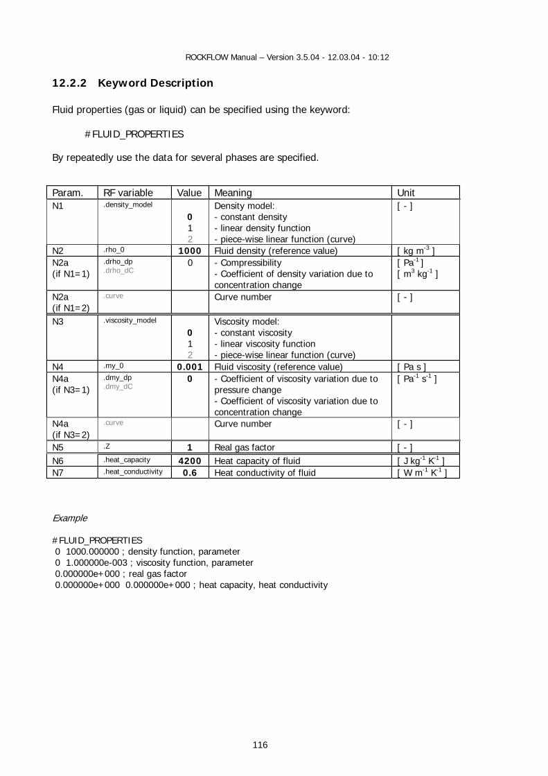
ROCKFLOW Manual – Version 3.5.04 - 12.03.04 - 10:12
116
12.2.2 Keyword Description Fluid properties (gas or liquid) can be specified using the keyword:
#FLUID_PROPERTIES By repeatedly use the data for several phases are specified. Param. RF variable Value Meaning Unit N1 .density_model
0 1 2
Density model: - constant density - linear density function - piece-wise linear function (curve)
[ - ]
N2 .rho_0 1000 Fluid density (reference value) [ kg m-3 ] N2a (if N1=1)
.drho_dp
.drho_dC 0 - Compressibility
- Coefficient of density variation due to concentration change
[ Pa-1 ] [ m3 kg-1 ]
N2a (if N1=2)
.curve Curve number [ - ]
N3 .viscosity_model 0 1 2
Viscosity model: - constant viscosity - linear viscosity function - piece-wise linear function (curve)
N4 .my_0 0.001 Fluid viscosity (reference value) [ Pa s ] N4a (if N3=1)
.dmy_dp
.dmy_dC 0 - Coefficient of viscosity variation due to
pressure change - Coefficient of viscosity variation due to concentration change
[ Pa-1 s-1 ]
N4a (if N3=2)
.curve Curve number [ - ]
N5 .Z 1 Real gas factor [ - ] N6 .heat_capacity 4200 Heat capacity of fluid [ J kg-1 K-1 ] N7 .heat_conductivity 0.6 Heat conductivity of fluid [ W m-1 K-1 ] Example #FLUID_PROPERTIES 0 1000.000000 ; density function, parameter 0 1.000000e-003 ; viscosity function, parameter 0.000000e+000 ; real gas factor 0.000000e+000 0.000000e+000 ; heat capacity, heat conductivity

ROCKFLOW Manual – Version 3.5.04 - 12.03.04 - 10:12
117
12.2.3 Ressource Description Source file Class Base class Ressource-ID
sh_mat.h/ccp CMaterialsFluid CPropertyPage IDD_MATERIALS_FLUID
material.h/c FLUID_PROPERTIES typedef
Control elements
Member variables
Member functions
RF-variables
IDC_EDIT_FP_1 IDC_EDIT_FP_2 IDC_EDIT_FP_3 IDC_EDIT_FP_4 IDC_EDIT_FP_5 IDC_EDIT_FP_6 IDC_EDIT_FP_7 IDC_EDIT_FP_8 IDC_EDIT_FP_9 IDC_EDIT_FP_10 IDC_EDIT_FP_11 IDC_EDIT_FP_12 IDC_EDIT_FP_13 IDC_EDIT_FP_14 IDC_EDIT_FP_15
m_dDensity_0 m_dDensity_p m_dDensity_C m_dDensity_T m_iDensityCurve m_dViscosity_0 m_dViscosity_p m_dViscosity_C m_dViscosity_T m_iViscosityCurve m_dHeatCapacity m_dHeatConductivity m_strFluidPhaseName m_iFluidPhase m_dRealGasFactor
.rho_0
.drho_dp
.drho_dC
.drho_dT
.curve
.my_0
.dmy_dp
.dmy_dC
.dmy_dT
.curve
.heat_capacity
.heat_conductivity
.name .Z
IDC_RADIO_FP_D1 IDC_RADIO_FP_V1
m_iSelectedDensityModel m_iSelectedViscosityModel
.density_model .viscosity_model
ID_CANCEL ID_OK
OnOK()
OnInitDialog() SetStatus_Dialog() GetFluidProperties() SetFluidProperties()
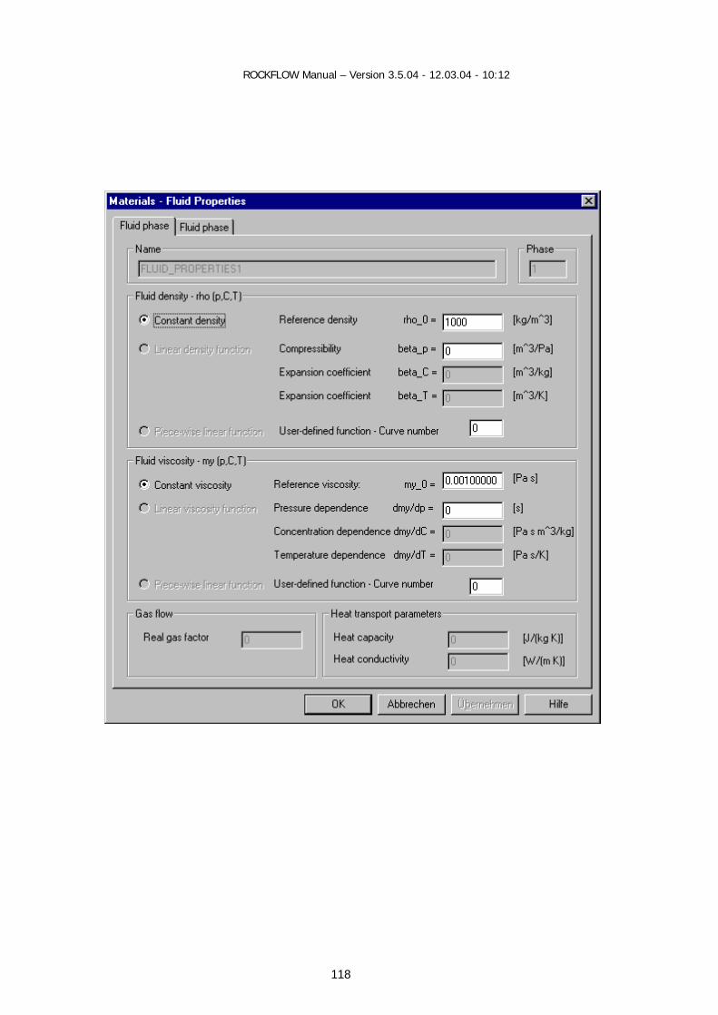
ROCKFLOW Manual – Version 3.5.04 - 12.03.04 - 10:12
118
ROCKFLOW Manual – Version 3.5.04 - 12.03.04 - 10:12
119
12.2.4 GUI Functions
12.2.4.1 Class Representation
CFluidProperties 12.2.4.2 View Functions void CRockflowView::OnMaterialsFluids() void CRockflowView::OnUpdateMaterialsFluids(CCmdUI* pCmdUI) PropertyPages are phase-related. Phase number is defined by selected model. 12.2.4.3 Dialog Data Exchange void CMaterialsFluid::GetFluidProperties(char *name)
fp = get_fp_object (name_fluid_properties_phase,sp) void CMaterialsFluid::SetFluidProperties(char *name)
fp = get_fp_object (name_fluid_properties_phase,sp) 12.2.4.4 Dialog Messages BOOL CMaterialsFluid::OnInitDialog() void CMaterialsFluid::OnOK() 12.2.4.5 Auxiliary Functions void CMaterialsFluid::SetStatus_Dialog(int m_iType)
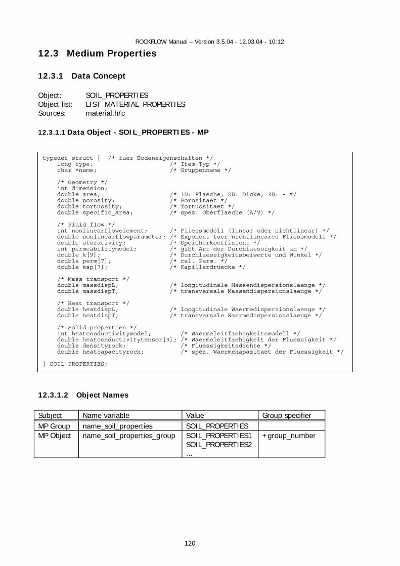
ROCKFLOW Manual – Version 3.5.04 - 12.03.04 - 10:12
120
12.3 Medium Properties
12.3.1 Data Concept Object: SOIL_PROPERTIES Object list: LIST_MATERIAL_PROPERTIES Sources: material.h/c
12.3.1.1 Data Object - SOIL_PROPERTIES - MP
12.3.1.2 Object Names Subject Name variable Value Group specifier MP Group name_soil_properties SOIL_PROPERTIES MP Object name_soil_properties_group SOIL_PROPERTIES1
SOIL_PROPERTIES2 ...
+group_number
typedef struct { /* fuer Bodeneigenschaften */ long type; /* Item-Typ */ char *name; /* Gruppenname */ /* Geometry */ int dimension; double area; /* 1D: Flaeche, 2D: Dicke, 3D: - */ double porosity; /* Porositaet */ double tortuosity; /* Tortuositaet */ double specific_area; /* spez. Oberflaeche (A/V) */ /* Fluid flow */ int nonlinearflowelement; /* Fliessmodell (linear oder nichtlinear) */ double nonlinearflowparameter; /* Exponent fuer nichtlineares Fliessmodell */ double storativity; /* Speicherkoeffizient */ int permeabilitymodel; /* gibt Art der Durchlaessigkeit an */ double k[9]; /* Durchlaessigkeitsbeiwerte und Winkel */ double perm[7]; /* rel. Perm. */ double kap[7]; /* Kapillardruecke */ /* Mass transport */ double massdispL; /* longitudinale Massendispersionslaenge */ double massdispT; /* transversale Massendispersionslaenge */ /* Heat transport */ double heatdispL; /* longitudinale Waermedispersionslaenge */ double heatdispT; /* transversale Waermedispersionslaenge */ /* Solid properties */ int heatconductivitymodel; /* Waermeleitfaehigkeitsmodell */ double heatconductivitytensor[3]; /* Waermeleitfaehigkeit der Fluessigkeit */ double densityrock; /* Fluessigkeitsdichte */ double heatcapacityrock; /* spez. Waermekapazitaet der Fluessigkeit */ } SOIL_PROPERTIES;

ROCKFLOW Manual – Version 3.5.04 - 12.03.04 - 10:12
121
12.3.1.3 Construction
SOIL_PROPERTIES *sp Medium properties data can be created either from reading the RFD file or interactively by use of the fluid properties dialog. - from RFD file
int FctSoilPropertiesNew(char *data, int found, FILE * f) sp = create_soil_properties(sp_name_this); insert_material_properties_list(sp);
- by soil properties dialog int CreateSoilPropertiesDefaults(long number)
AddSoilPropertiesDefaults() sp = create_soil_properties(sp_name_this); SetSoilPropertiesDefaults(sp)
RemoveSoilPropertiesObject(name); Destruction by list destruction 12.3.1.4 Data Access Access to MP objects is possible either from MAT list or from MAT table. - from MAT list by name
sp = GetSoilPropertiesObject(name,sp) // Object SetSoilPropertiesDefaults(sp) set_sp_property(property,sp) // Properties value = get_sp_property(sp)
- from MAT table by group number
value = GetSoilProperty(number) // Properties SetSoilPorosity(number, value)

ROCKFLOW Manual – Version 3.5.04 - 12.03.04 - 10:12
122
12.3.2 Keyword Description Medium properties (soil or rock) can be specified by use of keyword
#SOIL_PROPERTIES By repeatedly use data for several medium properties are specified. Param. RF variable Value Meaning Unit Geometric properties N1 .dimension
1 2 3
Element dimension [ - ]
N1a (if N1<3)
.area 1 Element exchange area (1-D) Element thickness (2-D)
[ m-2 ] [ m ]
N2 .porosity_model 0 Porosity model [ - ] N3 .porosity
0.2 Medium porosity [ m3 m-3 ]
N4 .tortuosity 1 Medium tortuosity [ - ] N5 .number_grain_classes 0 Number of lithological
components [ - ]
N5a (if N5=1) N5b
Grain class radius Grain class percentage
[ - ] [ - ]
Hydraulic properties N6 .nonlinearflowelement
0 1
Flow model: - Darcy (linear flow) - Forchheimer (nonlinear)
[ - ]
N6a .nonlinearflowparameter 1 Non-linear flow parameter [ - ] N7 .storativity 0.0 Specific storage coefficient [ Pa-1 ] N8 .permeability_model 0 Permeability model [ - ] N9 .permeability_tensor
0 1 3
Permeability characteristics - isotropic permeability - orthotropic permeability - distribution (see comment)
[ - ]
N10a (if N9=0)
.k[0] 0.0 Isotropic medium permeability [ m-2 ]
N10a N10b (if N9=1)
.k[0]
.k[1]
0.0 0.0
2-D element (N1=2) k_xx permeability k_yy permeability
[ m-2 ]
N11a N11b N11c (if N9=1)
.k[0]
.k[1]
.k[2]
0.0 0.0 0.0
3-D element (N1=3) k_xx permeability k_yy permeability k_zz permeability
[ m-2 ]
N12 - RP[7] see comments
.perm[0]
.perm[1]
.perm[2]
.perm[3]
.perm[4]
.perm[5]
.perm[6]
0.0 ...
Permeability functions k(S) relationships
N13 - CP[7] see comments
.kap[0]
.kap[1]
.kap[2]
.kap[3]
.kap[4]
.kap[5]
0.0 ...
Capillary pressure functions p(S) relationships
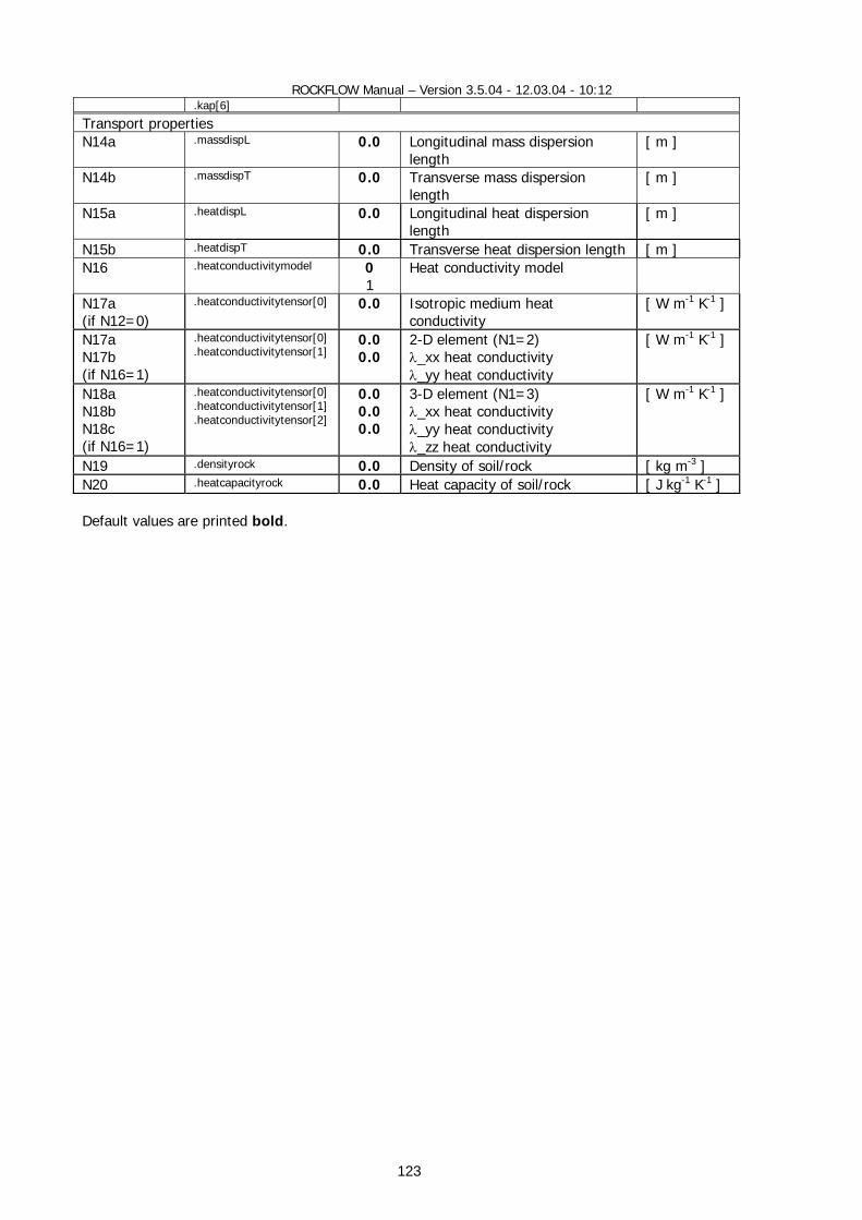
ROCKFLOW Manual – Version 3.5.04 - 12.03.04 - 10:12
123
.kap[6]
Transport properties N14a .massdispL 0.0 Longitudinal mass dispersion
length [ m ]
N14b .massdispT 0.0 Transverse mass dispersion length
[ m ]
N15a .heatdispL 0.0 Longitudinal heat dispersion length
[ m ]
N15b .heatdispT 0.0 Transverse heat dispersion length [ m ] N16 .heatconductivitymodel 0
1 Heat conductivity model
N17a (if N12=0)
.heatconductivitytensor[0] 0.0 Isotropic medium heat conductivity
[ W m-1 K-1 ]
N17a N17b (if N16=1)
.heatconductivitytensor[0]
.heatconductivitytensor[1] 0.0 0.0
2-D element (N1=2) λ_xx heat conductivity λ_yy heat conductivity
[ W m-1 K-1 ]
N18a N18b N18c (if N16=1)
.heatconductivitytensor[0]
.heatconductivitytensor[1]
.heatconductivitytensor[2]
0.0 0.0 0.0
3-D element (N1=3) λ_xx heat conductivity λ_yy heat conductivity λ_zz heat conductivity
[ W m-1 K-1 ]
N19 .densityrock 0.0 Density of soil/rock [ kg m-3 ] N20 .heatcapacityrock 0.0 Heat capacity of soil/rock [ J kg-1 K-1 ] Default values are printed bold.
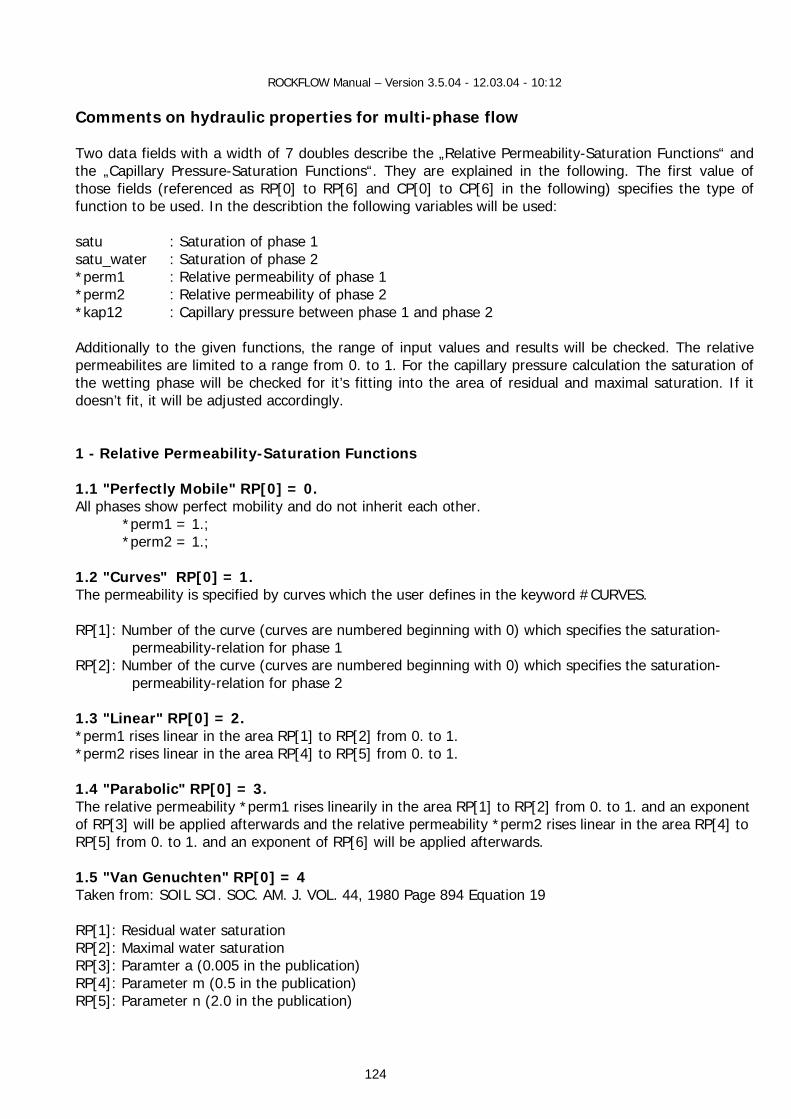
ROCKFLOW Manual – Version 3.5.04 - 12.03.04 - 10:12
124
Comments on hydraulic properties for multi-phase flow Two data fields with a width of 7 doubles describe the „Relative Permeability-Saturation Functions“ and the „Capillary Pressure-Saturation Functions“. They are explained in the following. The first value of those fields (referenced as RP[0] to RP[6] and CP[0] to CP[6] in the following) specifies the type of function to be used. In the describtion the following variables will be used: satu : Saturation of phase 1 satu_water : Saturation of phase 2 *perm1 : Relative permeability of phase 1 *perm2 : Relative permeability of phase 2 *kap12 : Capillary pressure between phase 1 and phase 2 Additionally to the given functions, the range of input values and results will be checked. The relative permeabilites are limited to a range from 0. to 1. For the capillary pressure calculation the saturation of the wetting phase will be checked for it’s fitting into the area of residual and maximal saturation. If it doesn’t fit, it will be adjusted accordingly. 1 - Relative Permeability-Saturation Functions 1.1 "Perfectly Mobile" RP[0] = 0. All phases show perfect mobility and do not inherit each other. *perm1 = 1.; *perm2 = 1.; 1.2 "Curves" RP[0] = 1. The permeability is specified by curves which the user defines in the keyword #CURVES. RP[1]: Number of the curve (curves are numbered beginning with 0) which specifies the saturation-
permeability-relation for phase 1 RP[2]: Number of the curve (curves are numbered beginning with 0) which specifies the saturation-
permeability-relation for phase 2 1.3 "Linear" RP[0] = 2. *perm1 rises linear in the area RP[1] to RP[2] from 0. to 1. *perm2 rises linear in the area RP[4] to RP[5] from 0. to 1. 1.4 "Parabolic" RP[0] = 3. The relative permeability *perm1 rises linearily in the area RP[1] to RP[2] from 0. to 1. and an exponent of RP[3] will be applied afterwards and the relative permeability *perm2 rises linear in the area RP[4] to RP[5] from 0. to 1. and an exponent of RP[6] will be applied afterwards. 1.5 "Van Genuchten" RP[0] = 4 Taken from: SOIL SCI. SOC. AM. J. VOL. 44, 1980 Page 894 Equation 19 RP[1]: Residual water saturation RP[2]: Maximal water saturation RP[3]: Paramter a (0.005 in the publication) RP[4]: Parameter m (0.5 in the publication) RP[5]: Parameter n (2.0 in the publication)
ROCKFLOW Manual – Version 3.5.04 - 12.03.04 - 10:12
125
s_eff = (satu_water - RP[1]) / (RP[2]- RP[1]); *perm2 = pow(s_eff, 2.) * (1 - pow((1 - pow(s_eff, 1. / m)), m)); *perm1 = 1. - *perm2; 1.6 "Haverkamp" RP[0] = 5 Take form: SOIL SCI. SOC. AM. J., VOL. 41, 1977, Pages 285ff RP[1]: Residual water saturation (0.075 in the publication) RP[2]: Maximal water saturation (0.287 in the publication) RP[3]: Parameter a (1.611e6 in the publication) RP[4]: Parameter b (4.74/3.96 = 1.197 in the publication) RP[5]: Parameter c (1.175e6 in the publication) *perm2 = c / (c + pow(-a * (satu_water - satu RP[2] - RP[1]) / satu_water, b)); *perm1 = 1. - *perm2; 1.7 "Brooks/Corey" RP[0] = 6 Taken from: Journal of the Irrigation and Drainage Division June, 1966 Pages 61ff RP[1]: Residual water saturation RP[2]: Maximal water saturation s_eff = (satu_water - RP[1]) / (RP[2] - RP[1]); *perm2 = pow(s_eff, 4.); /* Equation 4 */ *perm1 = pow(1. - s_eff, 2.) * (1. - pow(s_eff, 2.)); 2 - Capillary Pressure Functions 2.1 "No Capillary Pressure" CP[0] = 0. The capillary pressure is neglected. *kap12 = 0.; 2.2 "Curves" CP[0] = 1. The capillary pressure is specified by curves which the user defines in the keyword #CURVES. CP[1]: Number of the curve (curves are numbered beginning with 0) which specifies the relation
between the wetting phase (phase2) saturation and the capillary pressure. 2.3 "Linear" CP[0] = 2. p_cap rises linearily in the area CP[2] (maximal saturation of the wetting phase) to CP[1] (residual saturation of the wetting phase) from 0. to CP[3]. 2.4 "Parabolic" CP[0] = 3. The capillary pressure rises parabolicly in the area CP[2] (maximal saturation of the wetting phase) to CP[1] (residual saturation of the wetting phase) from 0. to CP[3] with an exponent of CP[4]. 2.5 "Van Genuchten" CP[0] = 4. Taken from: SOIL SIC. SOC. AM. J. VOL. 44, 1980 Page 894 Equation 21
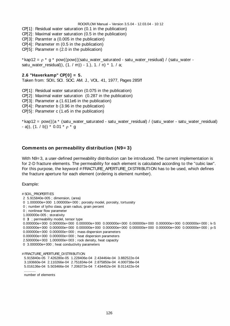
ROCKFLOW Manual – Version 3.5.04 - 12.03.04 - 10:12
126
CP[1]: Residual water saturation (0.1 in the publication) CP[2]: Maximal water saturation (0.5 in the publication) CP[3]: Paramter a (0.005 in the publication) CP[4]: Parameter m (0.5 in the publication) CP[5]: Parameter n (2.0 in the publication) *kap12 = ρ * g * pow((pow(((satu_water_saturated - satu_water_residual) / (satu_water - satu_water_residual)), (1. / m)) - 1.), 1. / n) * 1. / a; 2.6 "Haverkamp" CP[0] = 5. Taken from: SOIL SCI. SOC. AM. J., VOL. 41, 1977, Pages 285ff CP[1]: Residual water saturation (0.075 in the publication) CP[2]: Maximal water saturation (0.287 in the publication) CP[3]: Parameter a (1.611e6 in the publication) CP[4]: Parameter b (3.96 in the publication) CP[5]: Parameter c (1.e5 in the publication) *kap12 = pow(((a * (satu_water_saturated - satu_water_residual) / (satu_water - satu_water_residual) - a)), (1. / b)) * 0.01 * ρ * g Comments on permeability distribution (N9=3) With N9=3, a user-defined permeability distribution can be introduced. The current implementation is for 2-D fracture elements. The permeability for each element is calculated according to the "cubic law". For this purpose, the keyword #FRACTURE_APERTURE_DISTRIBUTION has to be used, which defines the fracture aperture for each element (ordering is element number). Example: #SOIL_PROPERTIES 2 5.915840e-005 ; dimension, (area) 0 1.000000e+000 1.000000e+000 ; porosity model, porosity, tortuosity 0 ; number of lytho class, grain radius, grain percent 0 ; nonlinear flow parameter 1.000000e-005 ; storativity 0 3 ; permeability model, tensor type 0.000000e+000 0.000000e+000 0.000000e+000 0.000000e+000 0.000000e+000 0.000000e+000 0.000000e+000 ; k-S 0.000000e+000 0.000000e+000 0.000000e+000 0.000000e+000 0.000000e+000 0.000000e+000 0.000000e+000 ; p-S 0.000000e+000 0.000000e+000 ; mass dispersion parameters 0.000000e+000 0.000000e+000 ; heat dispersion parameters 2.500000e+003 1.000000e+003 ; rock density, heat capacity 0 3.000000e+000 ; heat conductivity parameters #FRACTURE_APERTURE_DISTRIBUTION 5.915840e-05 7.426280e-05 1.228406e-04 2.434464e-04 3.882522e-04 3.193660e-04 2.110266e-04 2.751834e-04 2.875850e-04 4.000738e-04 5.016136e-04 5.503466e-04 7.206372e-04 7.434452e-04 8.011422e-04 ........... number of elements
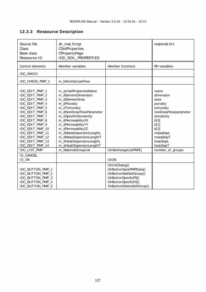
ROCKFLOW Manual – Version 3.5.04 - 12.03.04 - 10:12
127
12.3.3 Ressource Description Source file Class Base class Ressource-ID
sh_mat.h/ccp CSoilProperties CPropertyPage IDD_SOIL_PROPERTIES
material.h/c
Control elements
Member variables
Member functions
RF-variables
IDC_RADIO
-
IDC_CHECK_PMP_1
m_bNonDarcianFlow
IDC_EDIT_PMP_1 IDC_EDIT_PMP_2 IDC_EDIT_PMP_3 IDC_EDIT_PMP_4 IDC_EDIT_PMP_5 IDC_EDIT_PMP_6 IDC_EDIT_PMP_7 IDC_EDIT_PMP_8 IDC_EDIT_PMP_9 IDC_EDIT_PMP_10 IDC_EDIT_PMP_11 IDC_EDIT_PMP_12 IDC_EDIT_PMP_13 IDC_EDIT_PMP_14
m_strSoilPropertiesName m_iElementDimension m_dElementArea m_dPorosity m_dTortuosity m_dNonlinearFlowParameter m_dSpecificStorativity m_dPermeabilityXX m_dPermeabilityYY m_dPermeabilityZZ m_dMassDispersionLengthL m_dMassDispersionLengthT m_dHeatDispersionLengthL m_dHeatDispersionLengthT
name dimension area porosity tortuosity nonlinearflowparameter storativity k[0] k[1] k[2] massdispL massdispT heatdispL heatdispT
IDC_LIST_PMP m_MaterialGroupList OnSelchangeListPMP() number_of_groups
ID_CANCEL ID_OK
OnOK
IDC_BUTTON_PMP_1 IDC_BUTTON_PMP_2 IDC_BUTTON_PMP_3 IDC_BUTTON_PMP_4 IDC_BUTTON_PMP_5
OnInitDialog() OnButtonSavePMPData() OnButtonAddSoilGroup() OnButtonSpecifyPS() OnButtonSpecifyKS() OnButtonDeleteSoilGroup()
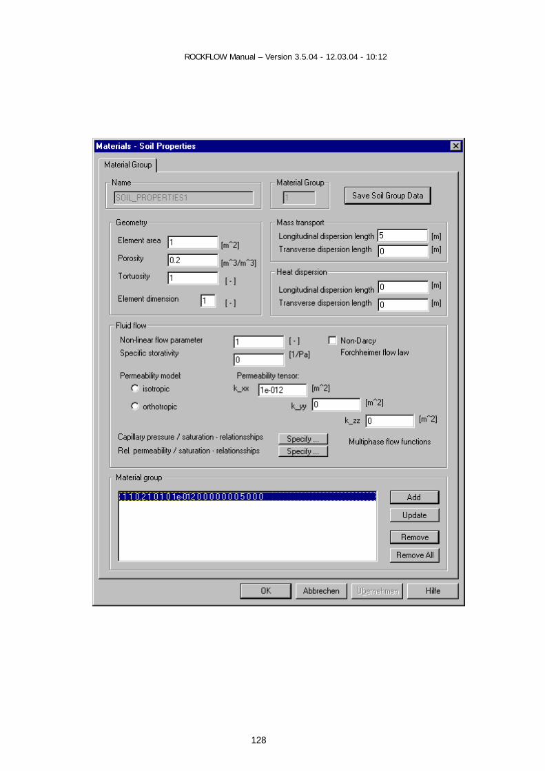
ROCKFLOW Manual – Version 3.5.04 - 12.03.04 - 10:12
128
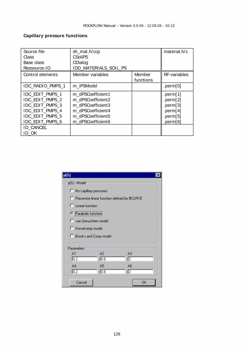
ROCKFLOW Manual – Version 3.5.04 - 12.03.04 - 10:12
129
Capillary pressure functions Source file Class Base class Ressource-ID
sh_mat.h/ccp CSoilPS CDialog IDD_MATERIALS_SOIL_PS
material.h/c
Control elements Member variables Member functions
RF-variables
IDC_RADIO_PMPS_1 m_iPSModel
.perm[0]
IDC_EDIT_PMPS_1 IDC_EDIT_PMPS_2 IDC_EDIT_PMPS_3 IDC_EDIT_PMPS_4 IDC_EDIT_PMPS_5 IDC_EDIT_PMPS_6
m_dPSCoefficient1 m_dPSCoefficient2 m_dPSCoefficient3 m_dPSCoefficient4 m_dPSCoefficient5 m_dPSCoefficient6
.perm[1]
.perm[2]
.perm[3]
.perm[4]
.perm[5]
.perm[6] ID_CANCEL ID_OK
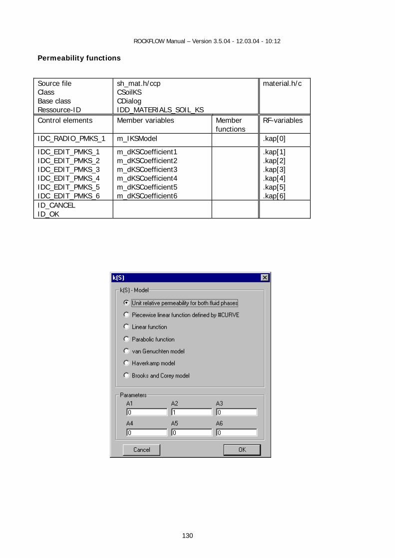
ROCKFLOW Manual – Version 3.5.04 - 12.03.04 - 10:12
130
Permeability functions Source file Class Base class Ressource-ID
sh_mat.h/ccp CSoilKS CDialog IDD_MATERIALS_SOIL_KS
material.h/c
Control elements Member variables Member functions
RF-variables
IDC_RADIO_PMKS_1 m_IKSModel
.kap[0]
IDC_EDIT_PMKS_1 IDC_EDIT_PMKS_2 IDC_EDIT_PMKS_3 IDC_EDIT_PMKS_4 IDC_EDIT_PMKS_5 IDC_EDIT_PMKS_6
m_dKSCoefficient1 m_dKSCoefficient2 m_dKSCoefficient3 m_dKSCoefficient4 m_dKSCoefficient5 m_dKSCoefficient6
.kap[1]
.kap[2]
.kap[3]
.kap[4]
.kap[5]
.kap[6] ID_CANCEL ID_OK

ROCKFLOW Manual – Version 3.5.04 - 12.03.04 - 10:12
131
12.3.4 GUI Functions
12.3.4.1 Class representation
CSoilProperties 12.3.4.2 View Functions void CRockflowView::OnMaterialsPorousMedium() void CRockflowView::OnUpdateMaterialsPorousMedium(CCmdUI* pCmdUI) 12.3.4.3 Dialog Data Exchange CSoilProperties::GetSoilData(int group_index)
sp = GetSoilPropertiesObject(sp_name_this,sp) CSoilProperties::SetSoilData(int group_index)
sp = GetSoilPropertiesObject(sp_name_this,sp) 12.3.4.4 Dialog Messages CSoilProperties::OnInitDialog() CSoilProperties::OnSelchangeListPMP() CSoilProperties::GetSoilData(int group_index)
sp = GetSoilPropertiesObject(sp_name_this,sp) CSoilProperties::OnButtonAddSoilGroup()
AddSoilPropertiesDefaults() CSoilProperties::OnButtonDeleteSoilGroup()
DeleteSoilPropertiesObject(sp_name_this,sp) RenameSoilPropertiesObjects()
CSoilProperties::OnButtonSavePMPData()
CSoilProperties::SetSoilData(int group_index) sp = GetSoilPropertiesObject(sp_name_this,sp)
Consecutive menues for specific data PS-relationship: CSoilPS KS-relationship: CSoilKS
12.4 Tracer Properties
12.4.1 Data Concept
Object: TRACER_PROPERTIES
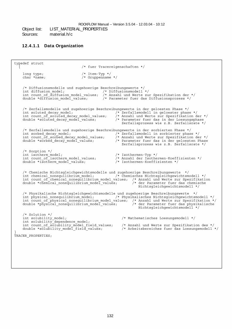
ROCKFLOW Manual – Version 3.5.04 - 12.03.04 - 10:12
132
Object list: LIST_MATERIAL_PROPERTIES Sources: material.h/c 12.4.1.1 Data Organization
typedef struct { /* fuer Tracereigenschaften */ long type; /* Item-Typ */ char *name; /* Gruppenname */ /* Diffusionsmodelle und zugehoerige Beschreibungswerte */ int diffusion_model; /* Diffusionsmodell */ int count_of_diffusion_model_values; /* Anzahl und Werte zur Spezifikation der */ double *diffusion_model_values; /* Parameter fuer das Diffusionsprozess */ /* Zerfallsmodelle und zugehoerige Beschreibungswerte in der geloesten Phase */ int soluted_decay_model; /* Zerfallsmodell in geloester phase */ int count_of_soluted_decay_model_values; /* Anzahl und Werte zur Spezifikation der */ double *soluted_decay_model_values; /* Parameter fuer das in der Loesungsphase Zerfallsprozess wie z.B. Zerfallsrate */ /* Zerfallsmodelle und zugehoerige Beschreibungswerte in der sorbierten Phase */ int sorbed_decay_model; /* Zerfallsmodell in sorbierter phase */ int count_of_sorbed_decay_model_values; /* Anzahl und Werte zur Spezifikation der */ double *sorbed_decay_model_values; /* Parameter fuer das in der geloesten Phase Zerfallsprozess wie z.B. Zerfallsrate */ /* Sorption */ int isotherm_model; /* Isothermen-Typ */ int count_of_isotherm_model_values; /* Anzahl der Isothermen-Koeffizienten */ double *isotherm_model_values; /* Isothermen-Koeffizienten */ /* Chemische Nichtsgleichgewichtsmodelle und zugehoerige Beschreibungswerte */ int chemical_nonequilibrium_model; /* Chemisches Nichtsgleichgewichtsmodell */ int count_of_chemical_nonequilibrium_model_values; /* Anzahl und Werte zur Spezifikation double *chemical_nonequilibrium_model_values; /* der Parameter fuer das chemische Nichtsgleichgewichtsmodell */ /* Physikalische Nichtsgleichgewichtsmodelle und zugehoerige Beschreibungswerte */ int physical_nonequilibrium_model; /* Physikalisches Nichtsgleichgewichtsmodell */ int count_of_physical_nonequilibrium_model_values; /* Anzahl und Werte zur Spezifikation */ double *physical_nonequilibrium_model_values; /* der Parameter fuer das physikalische Nichtsgleichgewichtsmodell */ /* Solution */ int solubility_model; /* Mathematisches Loesungsmodell */ int solubility_dependence_model; int count_of_solubility_model_field_values; /* Anzahl und Werte zur Spezifikation des */ double *solubility_model_field_values; /* Arbeitsbereiches fuer das Loesungsmodell */} TRACER_PROPERTIES;
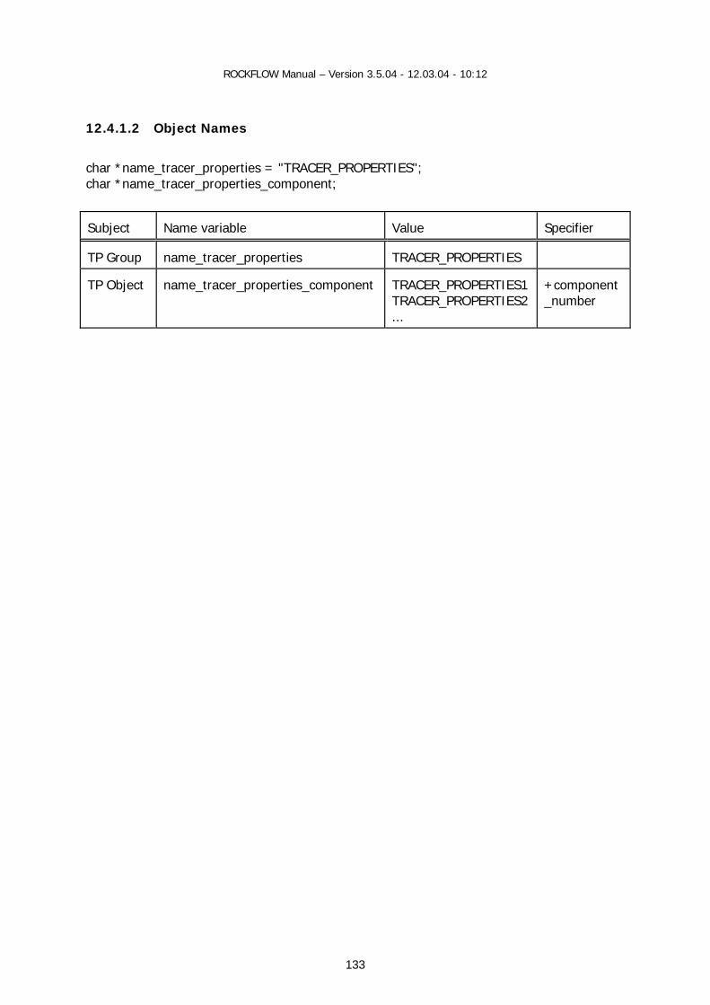
ROCKFLOW Manual – Version 3.5.04 - 12.03.04 - 10:12
133
12.4.1.2 Object Names
char *name_tracer_properties = "TRACER_PROPERTIES"; char *name_tracer_properties_component; Subject
Name variable
Value
Specifier
TP Group
name_tracer_properties
TRACER_PROPERTIES
TP Object
name_tracer_properties_component
TRACER_PROPERTIES1 TRACER_PROPERTIES2 ...
+component_number

ROCKFLOW Manual – Version 3.5.04 - 12.03.04 - 10:12
134
12.4.1.3 Construction TRACER_PROPERTIES = *tp Tracer properties data can be created either from reading a RFD file or interactively by use of the tracer properties dialog. • Construction from RFD file int FctTracerPropertiesNew (char *data, int found, FILE * f);
tp = create_tracer_properties(name); insert_material_properties_list(tp);
• Construction according to number of components
CreateTracerPropertiesDefaults(long number_of_components) AddTracerPropertiesObject(void); RemoveTracerPropertiesObject(char *name); RenameTracerPropertiesObjects(void);
• Destruction by MAT list destruction
void DestroyMaterialPropertiesList(void) 12.4.1.4 Data Access Access to TP objects is possible either from MAT list or from MAT table. • from MAT list by name: Data object:
tp = GetTracerPropertiesObject(char *name,TRACER_PROPERTIES *tp); Object properties:
set_tp_property(value,tp) value = get_tp_property(tp)
• from MAT table by group, phase, component numbers:
double GetTracerProperty(long index, long phase, long component);
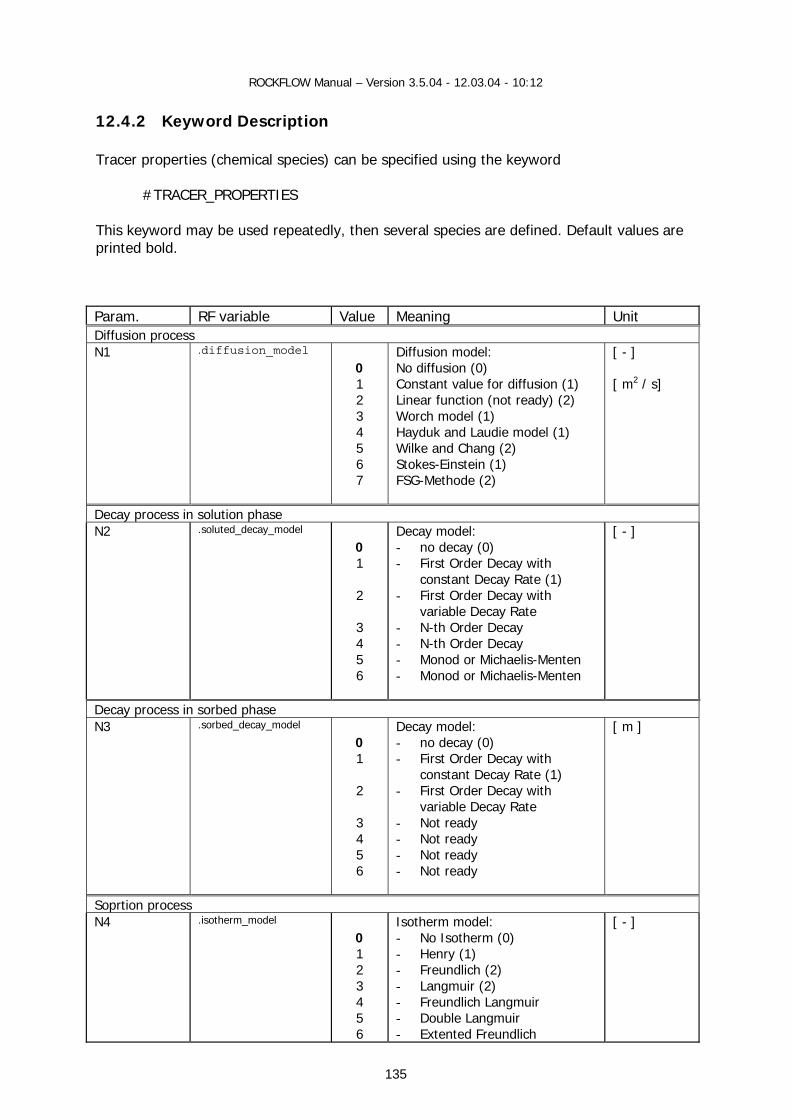
ROCKFLOW Manual – Version 3.5.04 - 12.03.04 - 10:12
135
12.4.2 Keyword Description Tracer properties (chemical species) can be specified using the keyword #TRACER_PROPERTIES This keyword may be used repeatedly, then several species are defined. Default values are printed bold. Param. RF variable Value Meaning Unit Diffusion process N1 .diffusion_model
0 1 2 3 4 5 6 7
Diffusion model: No diffusion (0) Constant value for diffusion (1) Linear function (not ready) (2) Worch model (1) Hayduk and Laudie model (1) Wilke and Chang (2) Stokes-Einstein (1) FSG-Methode (2)
[ - ] [ m2 / s]
Decay process in solution phase N2 .soluted_decay_model
0 1 2 3 4 5 6
Decay model: - no decay (0) - First Order Decay with
constant Decay Rate (1) - First Order Decay with
variable Decay Rate - N-th Order Decay - N-th Order Decay - Monod or Michaelis-Menten - Monod or Michaelis-Menten
[ - ]
Decay process in sorbed phase N3 .sorbed_decay_model
0 1 2 3 4 5 6
Decay model: - no decay (0) - First Order Decay with
constant Decay Rate (1) - First Order Decay with
variable Decay Rate - Not ready - Not ready - Not ready - Not ready
[ m ]
Soprtion process N4 .isotherm_model
0 1 2 3 4 5 6
Isotherm model: - No Isotherm (0) - Henry (1) - Freundlich (2) - Langmuir (2) - Freundlich Langmuir - Double Langmuir - Extented Freundlich
[ - ]

ROCKFLOW Manual – Version 3.5.04 - 12.03.04 - 10:12
136
7 8 9 10 11
- Gunary - ??? - Fitter-Sutton - Power - Modified Kielland
Chemical nonequilibrium model N5 .chemical_nonequilibrium_
model
0 1 2 3 4 5 6 7
Decay model: - No nonequilibrium model (0) - first order reaction (1) - n-th order reaction - reaction with langmuir kinetik - non reversible reaction - power kinetik - (first order reaction - n-th order reaction
[ - ]
Physical nonequilibrium model N6 .physical_nonequilibrium_
model
0 1 2
Decay model: - No nonequilibrium model (0) - Coats & Smith (1) - Coats & Smith
[ - ]
solubility_model N6 .solubility_model
0 1 2
Solution model: - no solution (0) - constant (λ , CS ) - Cosenza (?)
[ - ]
Default values are printed bold. Example #TRACER_PROPERTIES ; diffusion model 0 ; diffusion model type ; decay in soluted phase 1 2.0e-7 1.0 ; decay model type, decay rate in soluted phase, dummy ; decay in sorbed phase 1 2.0e-7 1.0 ; decay model type, decay rate in sorbed phase, dummy ; isotherm model 1 6.8e-5 ; isotherm model type (Henry), kd ; nonequilibrium chemical model 1 1.00e-4 ; chemical nonequilibrium model type, transfer rate value ; nonequilibrium physical model 0 ; physical nonequilibrium model type ; solution/dissolution model 0 ;model type

ROCKFLOW Manual – Version 3.5.04 - 12.03.04 - 10:12
12.4.3 Ressource Description Source file Class Base class Ressource-ID
sh_mat.h/ccp CTracerProperties CPropertyPage IDD_TRACER_PROPERTIES
material.h/c TRACER_PROPERTIES
Control elements Member variables Member functions
RF-variables
IDC_RADIO_TP_M1 IDC_RADIO_TP_M2 IDC_RADIO_TP_M3
m_iChemicalModel
IDC_RADIO_TP_1 IDC_RADIO_TP_2 IDC_RADIO_TP_3 IDC_RADIO_TP_M1 IDC_RADIO_TP_S1
m_iReactionIsothermType m_iChemicalModel m_iSolutionModel
OnRadioTP1 OnRadioTP2 OnRadioTP3
.type
IDC_EDIT_TP_1 IDC_EDIT_TP_3 IDC_EDIT_TP_4 IDC_EDIT_TP_5 IDC_EDIT_TP_6 IDC_EDIT_TP_7 IDC_EDIT_TP_8 IDC_EDIT_TP_9 IDC_EDIT_TP_10 IDC_EDIT_TP_11
m_strTracerComponentName m_dDiffusionConstant m_dDecayRate m_dSolubility m_dDissolutionRate m_dPartitioningCoefficient m_dSorptionCoefficientK1 m_dSorptionCoefficientK2 m_dExchangeParameter m_dDecayRateSorpted
.name
.molecular_diffusion .decay_rate .solubility .dissolution_rate .partitioning_coefficient .sorption_k1 .sorption_k2 .nonequilibrium_coefficient
IDC_LIST IDC_LIST_TP_1
m_LBMaterialGroup m_LBComponentNumber
OnSelchangeList1
ID_CANCEL ID_OK
OnInitDialog()
IDC_BUTTON_TP_1 IDC_BUTTON_TP_2 IDC_BUTTON_TP_3 IDC_BUTTON_TP_4 IDC_BUTTON_TP_5
OnSaveData() OnButtonAdd OnButtonUpdate OnButtonRemove OnButtonRemoveAll
137
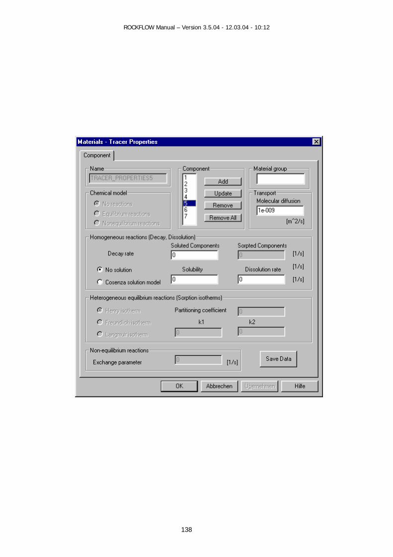
ROCKFLOW Manual – Version 3.5.04 - 12.03.04 - 10:12
138

ROCKFLOW Manual – Version 3.5.04 - 12.03.04 - 10:12
12.4.4 GUI Functions
12.4.4.1 Class representation
CTracerProperties 12.4.4.2 View Functions void CRockflowView::OnMaterialsChemicals() void CRockflowView::OnUpdateMaterialsChemicalSpecies(CCmdUI* pCmdUI) 12.4.4.3 Document Data Exchange void CRockflowView::WriteRF2Doc_MaterialProperties() void CRockflowView::WriteDoc2RF_MaterialProperties() 12.4.4.4 Dialog Data Exchange and Messages void CTracerProperties::OnInitDialog() void CMaterialsTracer::OnRadioTP1() void CMaterialsTracer::OnRadioTP2() void CMaterialsTracer::OnRadioTP3() void CMaterialsTracer::GetTracerData(char *name)
tp = GetTracerPropertiesObject(name,tp) void CMaterialsTracer::SetTracerData(char *name)
tp = GetTracerPropertiesObject(name,tp); void CMaterialsTracer::OnSaveData()
CTracerProperties::SetTracerData(name) tp = GetTracerPropertiesObject(name,tp)
void CMaterialsTracer::OnButtonAdd() void CMaterialsTracer::OnButtonUpdate() void CMaterialsTracer::OnButtonRemove() void CMaterialsTracer::OnButtonRemoveAll() void CMaterialsTracer::OnSelchangeList1() void CMaterialsTracer::UpdateList1() 12.4.4.5 Auxiliary Functions void CMaterialsTracer::StatusDialogResourceElements(void)
139
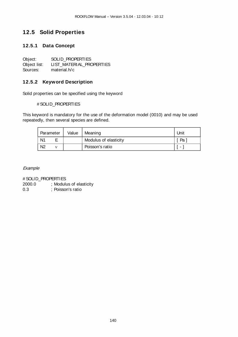
ROCKFLOW Manual – Version 3.5.04 - 12.03.04 - 10:12
12.5 Solid Properties
12.5.1 Data Concept
Object: SOLID_PROPERTIES Object list: LIST_MATERIAL_PROPERTIES Sources: material.h/c
12.5.2 Keyword Description Solid properties can be specified using the keyword #SOLID_PROPERTIES This keyword is mandatory for the use of the deformation model (0010) and may be used repeatedly, then several species are defined.
Parameter
Value
Meaning
Unit
N1 E Modulus of elasticity [ Pa ] N2 ν Poisson's ratio [ - ]
Example #SOLID_PROPERTIES 2000.0 ; Modulus of elasticity 0.3 ; Poisson's ratio
140
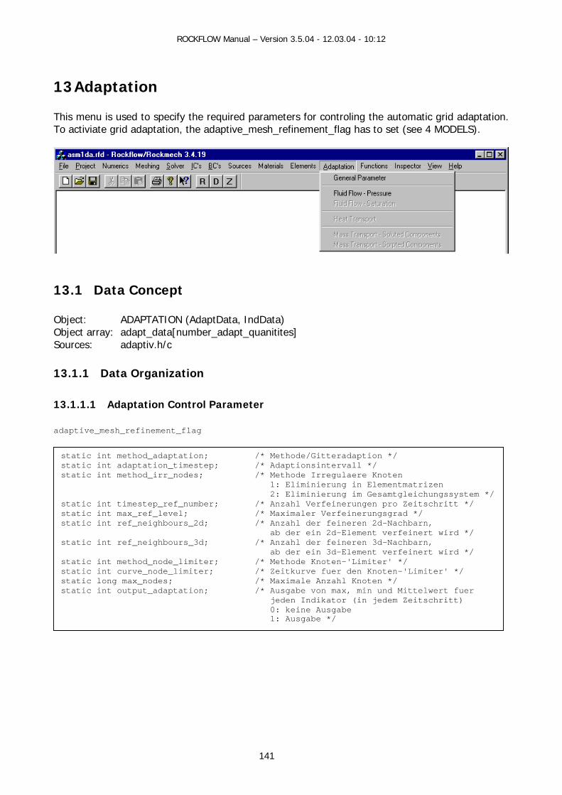
ROCKFLOW Manual – Version 3.5.04 - 12.03.04 - 10:12
141
13 Adaptation This menu is used to specify the required parameters for controling the automatic grid adaptation. To activiate grid adaptation, the adaptive_mesh_refinement_flag has to set (see 4 MODELS).
13.1 Data Concept Object: ADAPTATION (AdaptData, IndData) Object array: adapt_data[number_adapt_quanitites] Sources: adaptiv.h/c
13.1.1 Data Organization 13.1.1.1 Adaptation Control Parameter adaptive_mesh_refinement_flag
static int method_adaptation; /* Methode/Gitteradaption */ static int adaptation_timestep; /* Adaptionsintervall */ static int method_irr_nodes; /* Methode Irregulaere Knoten 1: Eliminierung in Elementmatrizen 2: Eliminierung im Gesamtgleichungssystem */ static int timestep_ref_number; /* Anzahl Verfeinerungen pro Zeitschritt */ static int max_ref_level; /* Maximaler Verfeinerungsgrad */ static int ref_neighbours_2d; /* Anzahl der feineren 2d-Nachbarn, ab der ein 2d-Element verfeinert wird */ static int ref_neighbours_3d; /* Anzahl der feineren 3d-Nachbarn, ab der ein 3d-Element verfeinert wird */ static int method_node_limiter; /* Methode Knoten-'Limiter' */ static int curve_node_limiter; /* Zeitkurve fuer den Knoten-'Limiter' */ static long max_nodes; /* Maximale Anzahl Knoten */ static int output_adaptation; /* Ausgabe von max, min und Mittelwert fuer jeden Indikator (in jedem Zeitschritt) 0: keine Ausgabe 1: Ausgabe */

ROCKFLOW Manual – Version 3.5.04 - 12.03.04 - 10:12
13.1.1.2 Adaptation Quantity Parameter
13.1.1.3 Adaptation Model Parameter Interface between Adaptation and Model
1 bRa
bRnnnnnnD
AdaptData *adap_data int number_adapt_quantities
typedef struct { int ref_quantity;
int method_ind; int number_phase_component; int quantity_max_ref_level; int coarsement_correction; long number_ind;
IndData *ind_data; int ref_nval0; int ref nval1;
} AdaptData;
*ad
*ad
*ad
adap data[i]
typedef struct { int ref_ind[3][2]; DoubleFuncLIII Ind[3][2]; double ref_param[3][2][3]; int ref_tol;
} IndData;
static int *index_phase_press; static int *index_temp; static int *index_comp_conc; static int *index_phase_satu; static int *index_comp_sorbed_conc; static int *index_comp_solute_conc;
142
3.1.2 Object Identification
y number F-FEM variable Identifier dapt_data[i].ref_quantity 0
1 2 3 4 5
fluid pressure tracer component temperature saturation soluted components sorpted components
y names F-FEM variable RF-Shell variable Value ame_adaptation_pressure ADAPTATION_PRESSURE ame_ adaptation_saturation ADAPTATION_SATURATION ame_adaptation_component ADAPTATION_COMPONENT ame_adaptation_temperature ADAPTATION_TEMPERATURE ame_adaptation_solute_component ADAPTATION_SOLUTE_COMPONENT ame_adaptation_sorbed_component
CAdaptation m_ap m_ap.m_strAPName
ADAPTATION_SORBED_COMPONENTata type: char [80] Data type: CString
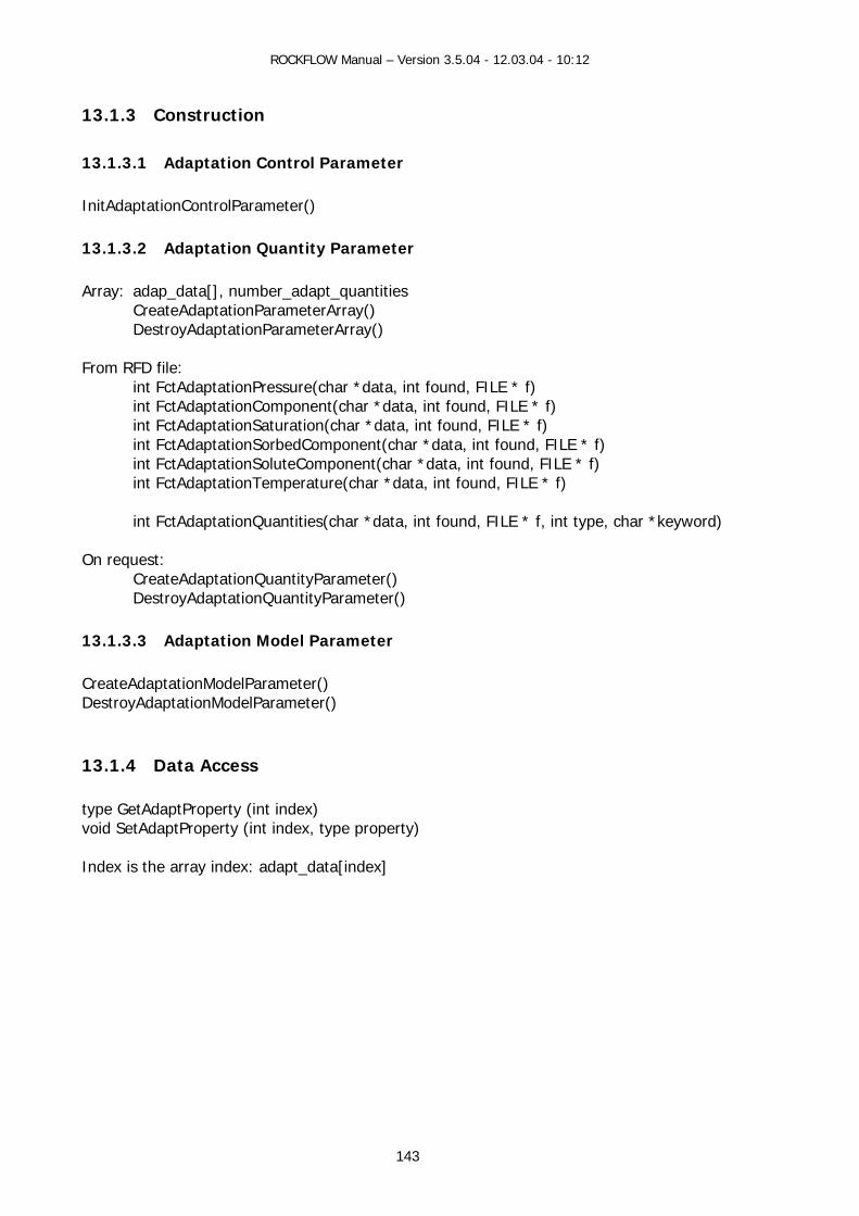
ROCKFLOW Manual – Version 3.5.04 - 12.03.04 - 10:12
13.1.3 Construction 13.1.3.1 Adaptation Control Parameter InitAdaptationControlParameter()
13.1.3.2 Adaptation Quantity Parameter Array: adap_data[], number_adapt_quantities
CreateAdaptationParameterArray() DestroyAdaptationParameterArray()
From RFD file:
int FctAdaptationPressure(char *data, int found, FILE * f) int FctAdaptationComponent(char *data, int found, FILE * f) int FctAdaptationSaturation(char *data, int found, FILE * f) int FctAdaptationSorbedComponent(char *data, int found, FILE * f) int FctAdaptationSoluteComponent(char *data, int found, FILE * f) int FctAdaptationTemperature(char *data, int found, FILE * f)
int FctAdaptationQuantities(char *data, int found, FILE * f, int type, char *keyword)
On request:
CreateAdaptationQuantityParameter() DestroyAdaptationQuantityParameter()
13.1.3.3 Adaptation Model Parameter CreateAdaptationModelParameter() DestroyAdaptationModelParameter()
13.1.4 Data Access type GetAdaptProperty (int index) void SetAdaptProperty (int index, type property) Index is the array index: adapt_data[index]
143

ROCKFLOW Manual – Version 3.5.04 - 12.03.04 - 10:12
13.2 Keyword Description The following keywords are available to specify grid adaptation parameters for field functions.
Keywords Name variables #ADAPTATION General control parameter #ADAPTATION_PRESSURE Quantity parameter for fluid pressure #ADAPTATION_COMPONENT Quantity parameter for components #ADAPTATION_SATURATION Quantity parameter for fluid saturation #ADAPTATION_SORBED_COMPONENT Quantity parameter for sorbed components #ADAPTATION_SOLUTE_COMPONENT Quantity parameter for soluted components #ADAPTATION_TEMPERATURE Quantity parameter for temperature
By repeatedly use of the keywords, the parameters for corresponding phases and components are specified.
13.2.1 Adaptation Control Parameter #ADAPTATION Parameter RF Variables Values Meaning
N1 method_adaptation int 0 1 2 3 4
Adaptation loop at time level: - no adaptation - calculation - adaptation - ... - calculation - adaptation – calculation - ... - calculation - calculation - adaptation - ... - calculation - adaptation – calculation - ... - calculation
if N1=3 adaptation_timestep int Time step number interval for adaptation if N1=4 adaptation_timestep int Time step number interval for adaptation N2 max_ref_level int Maximum refinement level N3 timestep_ref_number int Maximum refinement at time step N4 method_irr_nodes int
1 2
Regularization method: - at element level - at equation system level
N5 ref_neighbours_2d int Number of neighbours (2-D elements) to be refined (secondary criterium)
N6 ref_neighbours_3d int Number of neighbours (3-D elements) to be refined (secondary criterium)
N7 method_node_limiter int 0 1 2
Method for node limitation - no limitations - limitation 1 - limitation 2
if N7=1 curve_node_limiter int Time curve number max_nodes long
< 0 = 0 > 0
Maximum number of allowed nodes during grid adaptation - indicators will be changed to succeed - no limitations - indicators will be changed to succeed
if N7=2 curve_node_limiter int Time curve number max_nodes long Maximum number of allowed nodes during grid adaptation N8 output_adaptation Extended output information during simulation
144

ROCKFLOW Manual – Version 3.5.04 - 12.03.04 - 10:12
13.2.2 Adaptation Quantity Parameter #ADAPTATION_PRESSURE #ADAPTATION_COMPONENT #ADAPTATION_SATURATION #ADAPTATION_SORBED_COMPONENT #ADAPTATION_SOLUTE_COMPONENT #ADAPTATION_TEMPERATURE Parameter RF Variables Values Meaning
N1 method_ind int 0 1 2 3
Adaptation method: - using default values - for analytical estimators - for heuristical indicators - professional
Parameter RF Variables Values Meaning
N1 method_ind 1 For analytical estimators N2 coarsement_correction 0
1
N3 number_ind int Number of indicator data blocks N4... l=0;l<number_ind
ind_data[l].ref_tol int 0 1 2
Tolerance parameter: - based on absolute values - based on average values - based on maximum values
N5,6,7 k=0 k=1 k=2
ind_data[l].ref_param[0][0][k] Indicator parameter for 1-D diffusion elements - refinement border - coarsement border - dummy
N8,9,10 k=0 k=1 k=2
ind_data[l].ref_param[0][1][k] Indicator parameter for 1-D advection elements - refinement border - coarsement border - dummy
N11,12,13 k=0 k=1 k=2
ind_data[l].ref_param[1][0][k] Indicator parameter for 2-D diffusion elements - refinement border - coarsement border - dummy
N14,15,16 k=0 k=1 k=2
ind_data[l].ref_param[1][1][k] Indicator parameter for 2-D advection elements - refinement border - coarsement border - dummy
N17,18,19 k=0 k=1 k=2
ind_data[l].ref_param[2][0][k] Indicator parameter for 3-D diffusion elements - refinement border - coarsement border - dummy
N20,21,22 k=0 k=1 k=2
ind_data[l].ref_param[2][1][k] Indicator parameter for 3-D advection elements - refinement border - coarsement border - dummy
l data set index i element dimension j diffusion / advection k parameter
145
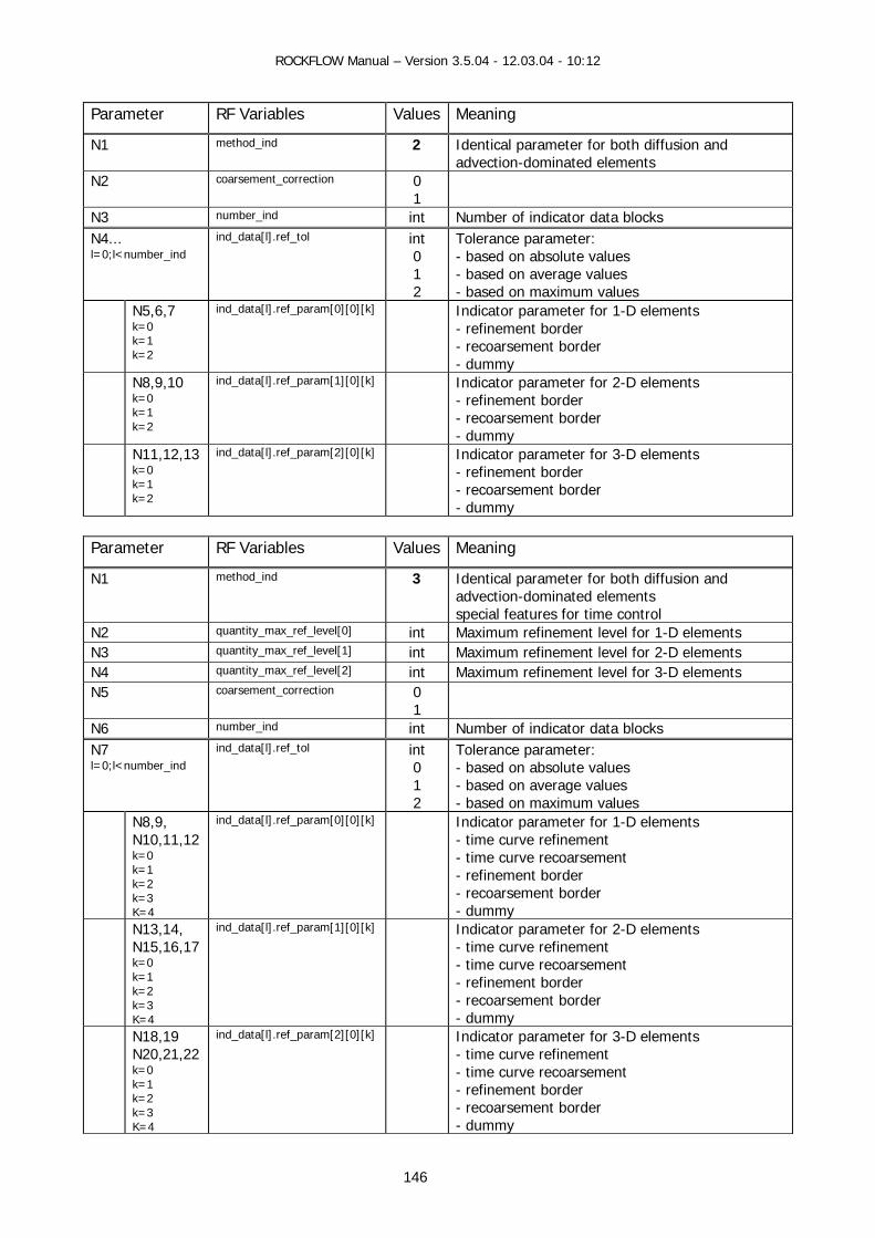
ROCKFLOW Manual – Version 3.5.04 - 12.03.04 - 10:12
Parameter RF Variables Values Meaning
N1 method_ind 2 Identical parameter for both diffusion and advection-dominated elements
N2 coarsement_correction 0 1
N3 number_ind int Number of indicator data blocks N4... l=0;l<number_ind
ind_data[l].ref_tol int 0 1 2
Tolerance parameter: - based on absolute values - based on average values - based on maximum values
N5,6,7 k=0 k=1 k=2
ind_data[l].ref_param[0][0][k] Indicator parameter for 1-D elements - refinement border - recoarsement border - dummy
N8,9,10 k=0 k=1 k=2
ind_data[l].ref_param[1][0][k] Indicator parameter for 2-D elements - refinement border - recoarsement border - dummy
N11,12,13 k=0 k=1 k=2
ind_data[l].ref_param[2][0][k] Indicator parameter for 3-D elements - refinement border - recoarsement border - dummy
Parameter RF Variables Values Meaning
N1 method_ind 3 Identical parameter for both diffusion and advection-dominated elements special features for time control
N2 quantity_max_ref_level[0] int Maximum refinement level for 1-D elements N3 quantity_max_ref_level[1] int Maximum refinement level for 2-D elements N4 quantity_max_ref_level[2] int Maximum refinement level for 3-D elements N5 coarsement_correction 0
1
N6 number_ind int Number of indicator data blocks N7 l=0;l<number_ind
ind_data[l].ref_tol int 0 1 2
Tolerance parameter: - based on absolute values - based on average values - based on maximum values
N8,9, N10,11,12 k=0 k=1 k=2 k=3 K=4
ind_data[l].ref_param[0][0][k] Indicator parameter for 1-D elements - time curve refinement - time curve recoarsement - refinement border - recoarsement border - dummy
N13,14, N15,16,17 k=0 k=1 k=2 k=3 K=4
ind_data[l].ref_param[1][0][k] Indicator parameter for 2-D elements - time curve refinement - time curve recoarsement - refinement border - recoarsement border - dummy
N18,19 N20,21,22 k=0 k=1 k=2 k=3 K=4
ind_data[l].ref_param[2][0][k] Indicator parameter for 3-D elements - time curve refinement - time curve recoarsement - refinement border - recoarsement border - dummy
146

ROCKFLOW Manual – Version 3.5.04 - 12.03.04 - 10:12
147
13.3 Ressource Description
13.3.1 General Adapation Parameter
Source file Class Base class Ressource-ID
sh_adp.h/ *.cpp CAdaptationGeneral CDialog IDD_ADP_GENERAL
gridadap.h/c
Control elements Member variables Member functions RF-variables OnInitDialog() IDC_CHECK_ADP_1 m_bIndicatePressure IDC_CHECK_ADP_2 m_bIndicateSaturation IDC_CHECK_ADP_3 m_bIndicateTemperature IDC_CHECK_ADP_4 m_bIndicateConcentration IDC_EDIT_ADP_G1 m_iMaximumRefinementLevel max_ref_level IDC_EDIT_ADP_G2 m_iMaximumPerTimeStep timestep_ref_number IDC_EDIT_ADP_G3 m_iRefineNeighboured2Delements ref_neighbours_2d IDC_EDIT_ADP_G4 m_iRefineNeighboured3DElements ref_neighbours_3d IDC_EDIT_ADP_G5 m_IMaximumNodes +max_nodes IDC_EDIT_ADP_G6 m_IDesiredNodes -max_nodes IDC_RADIO_ADP_M1 m_iAdaptationMethod method IDC_RADIO_ADP_M2 IDC_RADIO_ADP_O1 m_iAdaptationNodes IDC_RADIO_ADP_O2 IDC_RADIO_ADP_O3 IDC_BUTTON_ADP_1 OnEnablePressure() IDC_BUTTON_ADP_2 OnEnableSaturation() IDC_BUTTON_ADP_3 OnEnableTemperature() IDC_BUTTON_ADP_4 OnEnableConcentration() OnOK()
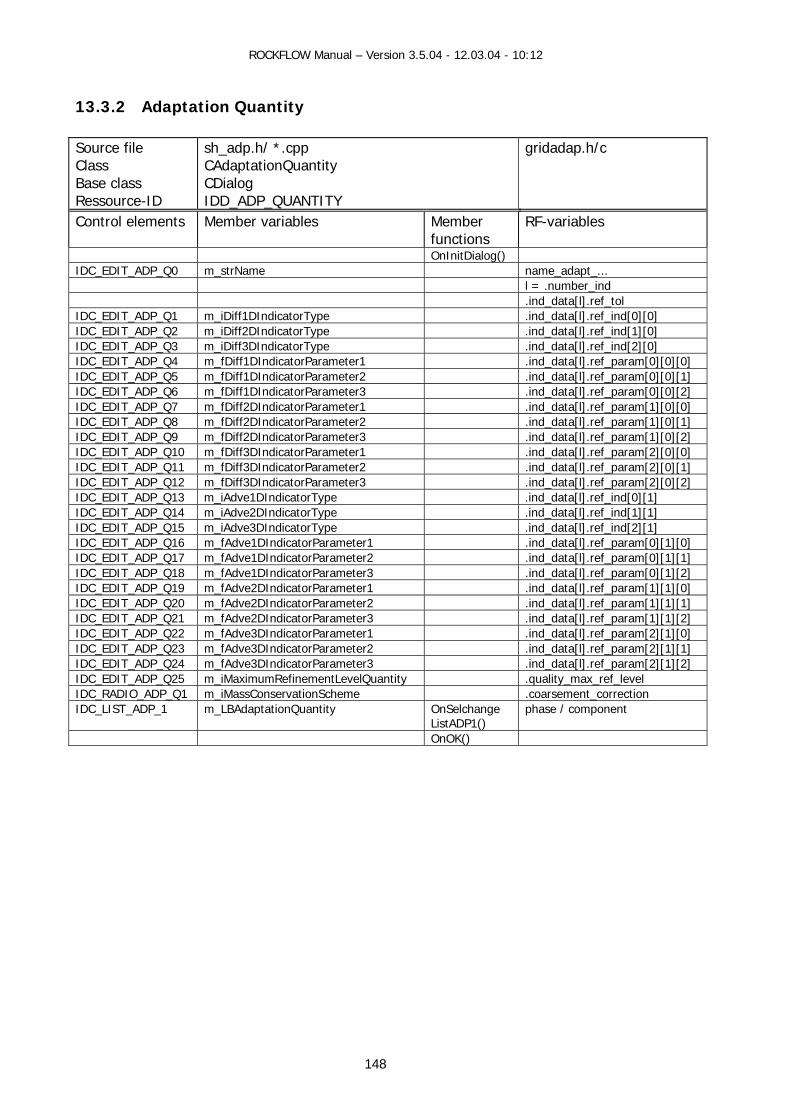
ROCKFLOW Manual – Version 3.5.04 - 12.03.04 - 10:12
13.3.2 Adaptation Quantity Source file Class Base class Ressource-ID
sh_adp.h/ *.cpp CAdaptationQuantity CDialog IDD_ADP_QUANTITY
gridadap.h/c
Control elements Member variables Member functions
RF-variables
OnInitDialog() IDC_EDIT_ADP_Q0 m_strName name_adapt_... l = .number_ind .ind_data[l].ref_tol IDC_EDIT_ADP_Q1 m_iDiff1DIndicatorType .ind_data[l].ref_ind[0][0] IDC_EDIT_ADP_Q2 m_iDiff2DIndicatorType .ind_data[l].ref_ind[1][0] IDC_EDIT_ADP_Q3 m_iDiff3DIndicatorType .ind_data[l].ref_ind[2][0] IDC_EDIT_ADP_Q4 m_fDiff1DIndicatorParameter1 .ind_data[l].ref_param[0][0][0] IDC_EDIT_ADP_Q5 m_fDiff1DIndicatorParameter2 .ind_data[l].ref_param[0][0][1] IDC_EDIT_ADP_Q6 m_fDiff1DIndicatorParameter3 .ind_data[l].ref_param[0][0][2] IDC_EDIT_ADP_Q7 m_fDiff2DIndicatorParameter1 .ind_data[l].ref_param[1][0][0] IDC_EDIT_ADP_Q8 m_fDiff2DIndicatorParameter2 .ind_data[l].ref_param[1][0][1] IDC_EDIT_ADP_Q9 m_fDiff2DIndicatorParameter3 .ind_data[l].ref_param[1][0][2] IDC_EDIT_ADP_Q10 m_fDiff3DIndicatorParameter1 .ind_data[l].ref_param[2][0][0] IDC_EDIT_ADP_Q11 m_fDiff3DIndicatorParameter2 .ind_data[l].ref_param[2][0][1] IDC_EDIT_ADP_Q12 m_fDiff3DIndicatorParameter3 .ind_data[l].ref_param[2][0][2] IDC_EDIT_ADP_Q13 m_iAdve1DIndicatorType .ind_data[l].ref_ind[0][1] IDC_EDIT_ADP_Q14 m_iAdve2DIndicatorType .ind_data[l].ref_ind[1][1] IDC_EDIT_ADP_Q15 m_iAdve3DIndicatorType .ind_data[l].ref_ind[2][1] IDC_EDIT_ADP_Q16 m_fAdve1DIndicatorParameter1 .ind_data[l].ref_param[0][1][0] IDC_EDIT_ADP_Q17 m_fAdve1DIndicatorParameter2 .ind_data[l].ref_param[0][1][1] IDC_EDIT_ADP_Q18 m_fAdve1DIndicatorParameter3 .ind_data[l].ref_param[0][1][2] IDC_EDIT_ADP_Q19 m_fAdve2DIndicatorParameter1 .ind_data[l].ref_param[1][1][0] IDC_EDIT_ADP_Q20 m_fAdve2DIndicatorParameter2 .ind_data[l].ref_param[1][1][1] IDC_EDIT_ADP_Q21 m_fAdve2DIndicatorParameter3 .ind_data[l].ref_param[1][1][2] IDC_EDIT_ADP_Q22 m_fAdve3DIndicatorParameter1 .ind_data[l].ref_param[2][1][0] IDC_EDIT_ADP_Q23 m_fAdve3DIndicatorParameter2 .ind_data[l].ref_param[2][1][1] IDC_EDIT_ADP_Q24 m_fAdve3DIndicatorParameter3 .ind_data[l].ref_param[2][1][2] IDC_EDIT_ADP_Q25 m_iMaximumRefinementLevelQuantity .quality_max_ref_level IDC_RADIO_ADP_Q1 m_iMassConservationScheme .coarsement_correction IDC_LIST_ADP_1 m_LBAdaptationQuantity OnSelchange
ListADP1() phase / component
OnOK()
148

ROCKFLOW Manual – Version 3.5.04 - 12.03.04 - 10:12
149
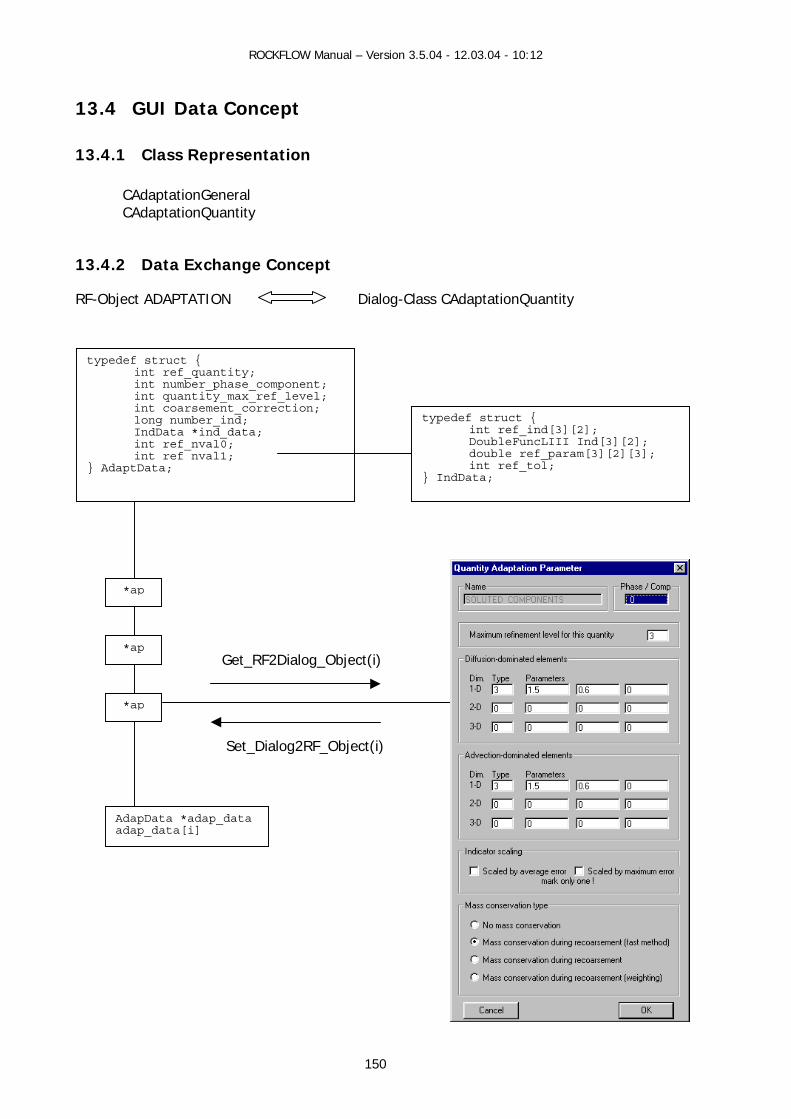
ROCKFLOW Manual – Version 3.5.04 - 12.03.04 - 10:12
150
13.4 GUI Data Concept
13.4.1 Class Representation
CAdaptationGeneral CAdaptationQuantity
13.4.2 Data Exchange Concept
RF-Object ADAPTATION Dialog-Class CAdaptationQuantity
*ap
*ap
*ap
AdapData *adap_data adap_data[i]
Get_RF2Dialog_Object(i)
Set_Dialog2RF_Object(i)
typedef struct { int ref_quantity; int number_phase_component; int quantity_max_ref_level; int coarsement_correction; long number_ind;
IndData *ind_data; int ref_nval0; int ref nval1;
} AdaptData;
typedef struct { int ref_ind[3][2]; DoubleFuncLIII Ind[3][2]; double ref_param[3][2][3]; int ref_tol;
} IndData;

ROCKFLOW Manual – Version 3.5.04 - 12.03.04 - 10:12
13.5 GUI Functions
13.5.1 View Functions (CRockflowView) View functions connect the mainframe menu (pull-down menus) with the individual dialogs.
void CRockflowView::OnAdaptationGeneral() void CRockflowView::OnAdaptationPressure() void CRockflowView::OnAdaptationSaturation() void CRockflowView::OnAdaptationTemperature() void CRockflowView::OnAdaptationSolutedComponents() void CRockflowView::OnAdaptationSorptedComponents()
13.5.2 Dialog Data Exchange
// i - is the index of array adap_data[i] void CAdaptationQuantity::Get_RF2Dialog_Object(int i)
// Transfer object data to dialog data void CAdaptationQuantity::Set_Dialog2RF_Object(int i) // Transfer dialog data to object data
13.5.3 Dialog Messages Handling - General adaptation data BOOL CAdaptationGeneral::OnInitDialog()
// Data transfer and initialization of ressource elements void CAdaptationGeneral::OnOK() // Data transfer - Quantity adaptation data BOOL CAdaptationQuantity::OnInitDialog()
// Data transfer and initialization of ressource elements void CAdaptationQuantity::OnSelchangeListADP1() // Select corresponding phase or component void CAdaptationQuantity::OnOK() // Data transfer
13.5.4 Auxiliary Functions void CAdaptationQuantity::StatusDialogResourceElements(int
C:\rockflow\manuals\rf_win\docs\15_Renumber.doc
151
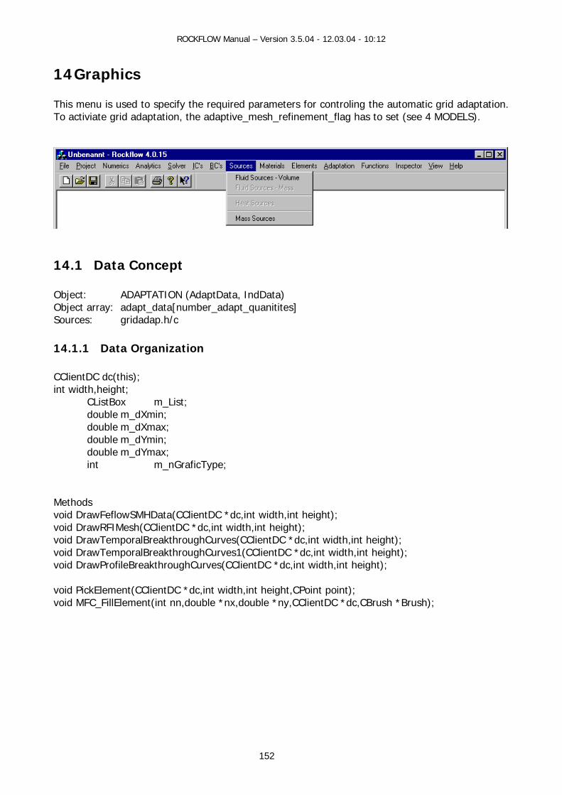
ROCKFLOW Manual – Version 3.5.04 - 12.03.04 - 10:12
14 Graphics This menu is used to specify the required parameters for controling the automatic grid adaptation. To activiate grid adaptation, the adaptive_mesh_refinement_flag has to set (see 4 MODELS).
14.1 Data Concept Object: ADAPTATION (AdaptData, IndData) Object array: adapt_data[number_adapt_quanitites] Sources: gridadap.h/c
14.1.1 Data Organization CClientDC dc(this); int width,height; CListBox m_List; double m_dXmin; double m_dXmax; double m_dYmin; double m_dYmax; int m_nGraficType; Methods void DrawFeflowSMHData(CClientDC *dc,int width,int height); void DrawRFIMesh(CClientDC *dc,int width,int height); void DrawTemporalBreakthroughCurves(CClientDC *dc,int width,int height); void DrawTemporalBreakthroughCurves1(CClientDC *dc,int width,int height); void DrawProfileBreakthroughCurves(CClientDC *dc,int width,int height); void PickElement(CClientDC *dc,int width,int height,CPoint point); void MFC_FillElement(int nn,double *nx,double *ny,CClientDC *dc,CBrush *Brush);
152

ROCKFLOW Manual – Version 3.5.04 - 12.03.04 - 10:12
14.1.2 Object Identification 14.1.3 Construction
14.1.4 Data Access
153

ROCKFLOW Manual – Version 3.5.04 - 12.03.04 - 10:12
14.2 Keyword Description The following keywords are available to specify grid adaptation parameters.
Keywords Name variables #ADAPTATION General control parameter #ADAPTATION_PRESSURE #ADAPTATION_COMPONENT #ADAPTATION_SATURATION #ADAPTATION_SORBED_COMPONENT #ADAPTATION_SOLUTE_COMPONENT
By repeatedly use of the keywords, the parameters for corresponding phases and components are specified.
154
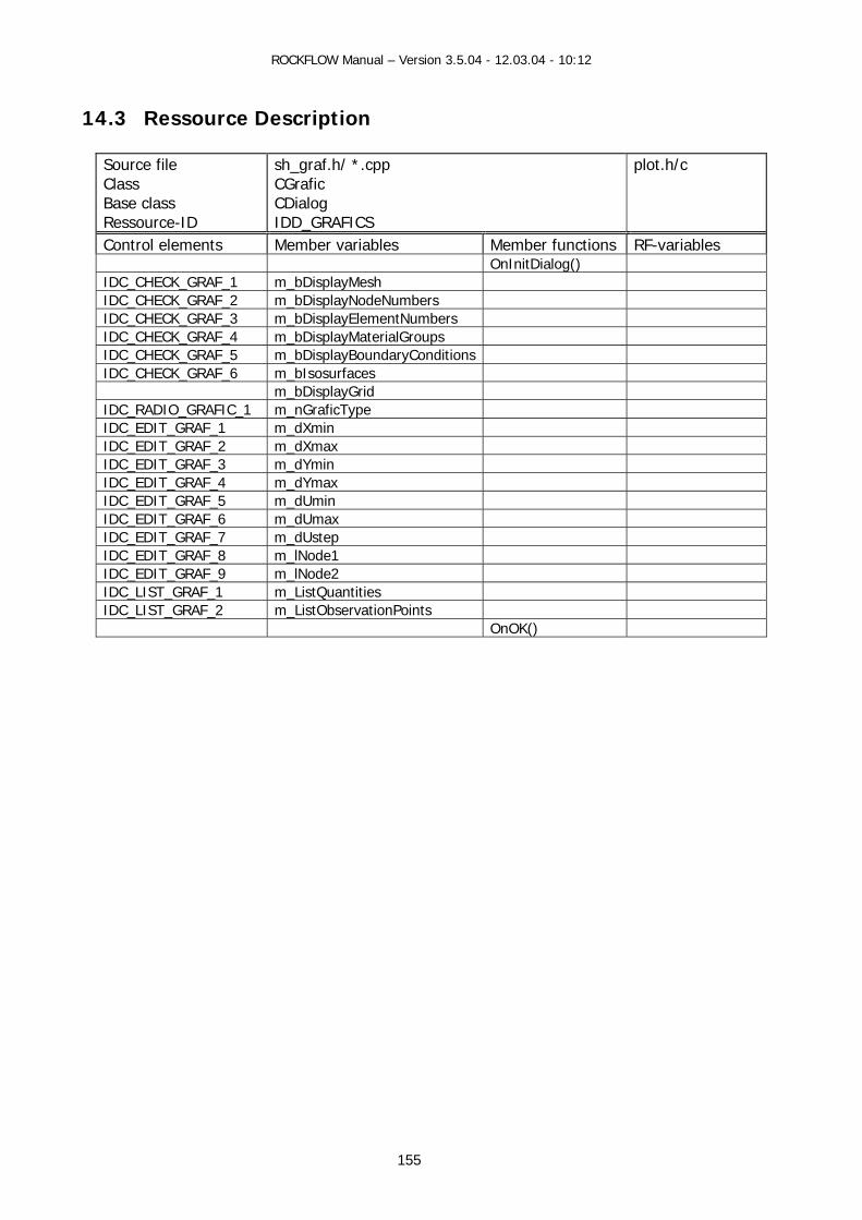
ROCKFLOW Manual – Version 3.5.04 - 12.03.04 - 10:12
14.3 Ressource Description
Source file Class Base class Ressource-ID
sh_graf.h/ *.cpp CGrafic CDialog IDD_GRAFICS
plot.h/c
Control elements Member variables Member functions RF-variables OnInitDialog() IDC_CHECK_GRAF_1 m_bDisplayMesh IDC_CHECK_GRAF_2 m_bDisplayNodeNumbers IDC_CHECK_GRAF_3 m_bDisplayElementNumbers IDC_CHECK_GRAF_4 m_bDisplayMaterialGroups IDC_CHECK_GRAF_5 m_bDisplayBoundaryConditions IDC_CHECK_GRAF_6 m_bIsosurfaces m_bDisplayGrid IDC_RADIO_GRAFIC_1 m_nGraficType IDC_EDIT_GRAF_1 m_dXmin IDC_EDIT_GRAF_2 m_dXmax IDC_EDIT_GRAF_3 m_dYmin IDC_EDIT_GRAF_4 m_dYmax IDC_EDIT_GRAF_5 m_dUmin IDC_EDIT_GRAF_6 m_dUmax IDC_EDIT_GRAF_7 m_dUstep IDC_EDIT_GRAF_8 m_lNode1 IDC_EDIT_GRAF_9 m_lNode2 IDC_LIST_GRAF_1 m_ListQuantities IDC_LIST_GRAF_2 m_ListObservationPoints OnOK()
155
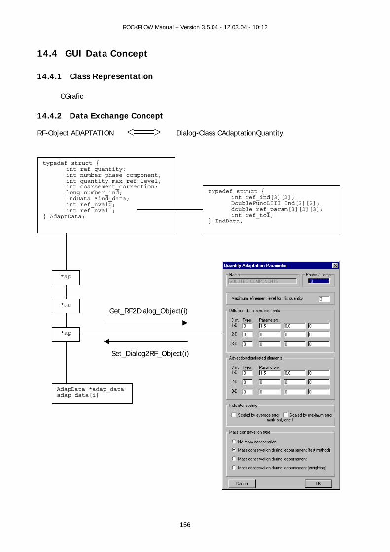
ROCKFLOW Manual – Version 3.5.04 - 12.03.04 - 10:12
156
14.4 GUI Data Concept
14.4.1 Class Representation
CGrafic
14.4.2 Data Exchange Concept
RF-Object ADAPTATION Dialog-Class CAdaptationQuantity
*ap
*ap
*ap
AdapData *adap_data adap_data[i]
Get_RF2Dialog_Object(i)
Set_Dialog2RF_Object(i)
typedef struct { int ref_quantity; int number_phase_component; int quantity_max_ref_level; int coarsement_correction; long number_ind;
IndData *ind_data; int ref_nval0; int ref nval1;
} AdaptData;
typedef struct { int ref_ind[3][2]; DoubleFuncLIII Ind[3][2]; double ref_param[3][2][3]; int ref_tol;
} IndData;
ROCKFLOW Manual – Version 3.5.04 - 12.03.04 - 10:12
14.5 GUI Functions
14.5.1 View Functions (CRockflowView) void CRockflowView::OnDraw(CDC* pDC)
14.5.2 Dialog Data Exchange
// i - is the index of array adap_data[i] void CAdaptationQuantity::Get_RF2Dialog_Object(int i)
// Transfer object data to dialog data void CAdaptationQuantity::Set_Dialog2RF_Object(int i) // Transfer dialog data to object data
14.5.3 Dialog Messages Handling - General adaptation data BOOL CAdaptationGeneral::OnInitDialog()
// Data transfer and initialization of ressource elements void CAdaptationGeneral::OnOK() // Data transfer - Quantity adaptation data BOOL CAdaptationQuantity::OnInitDialog()
// Data transfer and initialization of ressource elements void CAdaptationQuantity::OnSelchangeListADP1() // Select corresponding phase or component void CAdaptationQuantity::OnOK() // Data transfer
14.5.4 Auxiliary Functions void CAdaptationQuantity::StatusDialogResourceElements(int i)
157

ROCKFLOW Manual – Version 3.5.04 - 12.03.04 - 10:12
Contents 1 Data Concept.....................................................................................................................5
1.1 ROCKFLOW Objects.....................................................................................................5 1.2 ROCKFLOW Source Files ..............................................................................................7
2 Data Files ..........................................................................................................................8 2.1 Data Formats ..............................................................................................................8 2.2 File handling GUI functions ..........................................................................................9 2.3 Data Converter..........................................................................................................10 2.4 RF Keyword Reference...............................................................................................11
3 Simulation .......................................................................................................................13 4 Model ..............................................................................................................................14
4.1 Data Concept ............................................................................................................14 4.1.1 Simulation Control Data ......................................................................................15 4.1.2 Model Node Data ................................................................................................16 4.1.3 Model Element Data............................................................................................17 4.1.4 Model Output Data .............................................................................................18
4.2 Keyword Description..................................................................................................19 4.2.1 Project Title........................................................................................................19 4.2.2 Model.................................................................................................................20
4.3 Ressource Description................................................................................................23 Data and GUI Functions.......................................................................................................24 Data and GUI Functions.......................................................................................................24
4.3.1 Data Construction Functions ................................................................................24 4.3.2 View Functions (CRockflowView)..........................................................................24 4.3.3 Document Data Exchange ...................................................................................24 4.3.4 Dialog Message and Data Exchange.....................................................................24
5 Time Discretization...........................................................................................................25 5.1 Data Concept ............................................................................................................25
5.1.1 Data Object ........................................................................................................25 5.1.2 Construction .......................................................................................................25
5.2 Keyword Description..................................................................................................27 5.3 Resource Description .................................................................................................28 5.4 Data and GUI Functions.............................................................................................29
5.4.1 RF Data Functions...............................................................................................29 5.4.2 View Functions (CRockflowView)..........................................................................29 5.4.3 Document Data Exchange ...................................................................................29 5.4.4 Dialog Data Exchange and Message Functions......................................................29 5.4.5 Auxiliary Functions..............................................................................................29
6 Data Output.....................................................................................................................30 6.1 Nodal Results ............................................................................................................30
6.1.1 Data Concept .....................................................................................................30 6.1.2 Keyword Description ...........................................................................................31 6.1.3 Resource Description ..........................................................................................32 6.1.4 Data and GUI Functions ......................................................................................34
6.2 Temporal Profiles ......................................................................................................35 6.2.1 Data Concept .....................................................................................................35 6.2.2 Keyword Description ...........................................................................................36 6.2.3 Resource Description ..........................................................................................37 6.2.4 Data and GUI Functions ......................................................................................38
6.3 Output Object ...........................................................................................................39 6.4 Backup Files..............................................................................................................40
7 Numerical Method ............................................................................................................41 7.1 Data Concept ............................................................................................................41
158

ROCKFLOW Manual – Version 3.5.04 - 12.03.04 - 10:12
7.1.1 Data object ........................................................................................................41 7.1.2 Construction .......................................................................................................42 7.1.3 Names ...............................................................................................................42 7.1.4 Data Access........................................................................................................42
7.2 Keyword Description..................................................................................................43 7.3 Resource Description .................................................................................................48 7.4 GUI Functions ...........................................................................................................49
7.4.1 RF Data Functions...............................................................................................49 7.4.2 View Functions ...................................................................................................49 7.4.3 Document Data Exchange ...................................................................................49 7.4.4 Dialog Functions .................................................................................................49 7.4.5 Auxiliary Function ...............................................................................................49
8 Solver..............................................................................................................................50 8.1 Linear Equation Solver ...............................................................................................50
8.1.1 Data Concept .....................................................................................................50 8.1.2 Keyword Description ...........................................................................................55 8.1.3 Ressource Description .........................................................................................57 8.1.4 GUI Functions.....................................................................................................58
8.2 Non-Linear Solver......................................................................................................59 8.2.1 Data Concept .....................................................................................................59 8.2.2 Solver Implementation ........................................................................................62 8.2.3 Keyword Description ...........................................................................................63 8.2.4 Ressource Description .........................................................................................64 8.2.5 GUI Functions.....................................................................................................65
8.3 Iteration Process .......................................................................................................66 8.3.1 Data Concept .....................................................................................................66 8.3.2 Keyword Description ...........................................................................................69 8.3.3 Ressource Description .........................................................................................70 8.3.4 GUI Functions.....................................................................................................71
9 Initial Conditions ..............................................................................................................72 9.1 Data Concept ............................................................................................................72
9.1.1 Data Organization...............................................................................................72 9.1.2 Object Names.....................................................................................................73 9.1.3 Data Construction ...............................................................................................73 9.1.4 Data Access........................................................................................................73
9.2 Keyword Description..................................................................................................74 9.3 Ressource Description................................................................................................75 9.4 GUI Data Concept .....................................................................................................77
9.4.1 Class Representation...........................................................................................77 9.4.2 Document Data Concept .....................................................................................77 9.4.3 Object Data Concept ...........................................................................................78
9.5 GUI Functions ...........................................................................................................79 9.5.1 View Functions (CRockflowView)..........................................................................79 9.5.2 Document Data Exchange ...................................................................................79 9.5.3 Dialog Data Exchange .........................................................................................79 9.5.4 Dialog Messages .................................................................................................79 9.5.5 Functions for String Concept................................................................................80 9.5.6 Auxiliary Functions..............................................................................................80
10 Boundary Conditions .....................................................................................................82 10.1 Data Concept.........................................................................................................82
10.1.1 Data Organization...............................................................................................82 10.1.2 Object Names.....................................................................................................83 10.1.3 Construction .......................................................................................................83 10.1.4 Data Access........................................................................................................84
159
ROCKFLOW Manual – Version 3.5.04 - 12.03.04 - 10:12
10.2 Keyword Description...............................................................................................85 10.3 Ressource Description ............................................................................................88 10.4 GUI Data Concept ..................................................................................................90
10.4.1 Class Representation...........................................................................................90 10.4.2 Document Data Concept .....................................................................................90 10.4.3 Object Data Concept ...........................................................................................91
10.5 GUI Functions ........................................................................................................92 10.5.1 View Functions (CRockflowView)..........................................................................92 10.5.2 Document Data Exchange ...................................................................................92 10.5.3 Dialog Data Exchange .........................................................................................92 10.5.4 Dialog Messages .................................................................................................92 10.5.5 Functions for String Concept................................................................................93 10.5.6 Auxiliary Functions..............................................................................................93
11 Sources........................................................................................................................94 11.1 Data Concept.........................................................................................................94
11.1.1 Source-Term Objects (SS-O) ...............................................................................94 11.1.2 Source-Term Matrices (ST-OM)............................................................................97
11.2 Object Communication ...........................................................................................98 11.2.1 ST-ObjectList (ST-OL) <---> ST-ObjectMatrix (ST-OM) .........................................98 11.2.2 SS-ObjectMatrix (ST-OM) <---> LES ....................................................................98
11.3 Keyword Description...............................................................................................99 11.4 Input Examples.................................................................................................... 101 11.5 ........................................................................................................................... 101 11.5 ........................................................................................................................... 102 11.5 .............................................................................................................................. 103 11.6 Ressource Description .......................................................................................... 104 11.7 GUI Data Concept ................................................................................................ 106
11.7.1 Class Representation......................................................................................... 106 11.7.2 Object Data Concept ......................................................................................... 106 11.7.3 Document Data Concept ................................................................................... 107
11.8 GUI Functions ...................................................................................................... 108 11.8.1 View Functions (CRockflowView)........................................................................ 108 11.8.2 Document Data Exchange ................................................................................. 108 11.8.3 Dialog Data Exchange ....................................................................................... 108 11.8.4 Dialog Messages ............................................................................................... 108 11.8.5 Functions for String Concept.............................................................................. 109 11.8.6 Auxiliary Functions............................................................................................ 109
12 Material Properties ...................................................................................................... 110 12.1 Data Concept....................................................................................................... 110
12.1.1 Material Properties List...................................................................................... 111 12.1.2 Material Properties Groups ................................................................................ 112 12.1.3 Material Properties Table................................................................................... 113
12.2 Fluid Properties .................................................................................................... 114 12.2.1 Data Concept ................................................................................................... 114 12.2.2 Keyword Description ......................................................................................... 116 12.2.3 Ressource Description ....................................................................................... 117 12.2.4 GUI Functions................................................................................................... 119
12.3 Medium Properties ............................................................................................... 120 12.3.1 Data Concept ................................................................................................... 120 12.3.2 Keyword Description ......................................................................................... 122 12.3.3 Ressource Description ....................................................................................... 127 12.3.4 GUI Functions................................................................................................... 131
12.4 Tracer Properties ................................................................................................. 131 12.4.1 Data Concept ................................................................................................... 131
160

ROCKFLOW Manual – Version 3.5.04 - 12.03.04 - 10:12
12.4.2 Keyword Description ......................................................................................... 135
12.4.3 Ressource Description ....................................................................................... 137 12.4.4 GUI Functions................................................................................................... 139
12.5 Solid Properties.................................................................................................... 140 12.5.1 Data Concept ................................................................................................... 140 12.5.2 Keyword Description ......................................................................................... 140
13 Adaptation ................................................................................................................. 141 13.1 Data Concept....................................................................................................... 141
13.1.1 Data Organization............................................................................................. 141 13.1.2 Object Identification.......................................................................................... 142 13.1.3 Construction ..................................................................................................... 143 13.1.4 Data Access...................................................................................................... 143
13.2 Keyword Description............................................................................................. 144 13.2.1 Adaptation Control Parameter............................................................................ 144 13.2.2 Adaptation Quantity Parameter.......................................................................... 145
13.3 Ressource Description .......................................................................................... 147 13.3.1 General Adapation Parameter ............................................................................ 147 13.3.2 Adaptation Quantity .......................................................................................... 148
13.4 GUI Data Concept ................................................................................................ 150 13.4.1 Class Representation......................................................................................... 150 13.4.2 Data Exchange Concept .................................................................................... 150
13.5 GUI Functions ...................................................................................................... 151 13.5.1 View Functions (CRockflowView)........................................................................ 151 13.5.2 Dialog Data Exchange ....................................................................................... 151 13.5.3 Dialog Messages Handling ................................................................................. 151 13.5.4 Auxiliary Functions............................................................................................ 151
14 Graphics..................................................................................................................... 152 14.1 Data Concept....................................................................................................... 152
14.1.1 Data Organization............................................................................................. 152 14.1.2 Object Identification.......................................................................................... 153 14.1.3 Construction ..................................................................................................... 153 14.1.4 Data Access...................................................................................................... 153
14.2 Keyword Description............................................................................................. 154 14.3 Ressource Description .......................................................................................... 155 14.4 GUI Data Concept ................................................................................................ 156
14.4.1 Class Representation......................................................................................... 156 14.4.2 Data Exchange Concept .................................................................................... 156
14.5 GUI Functions ...................................................................................................... 157 14.5.1 View Functions (CRockflowView)........................................................................ 157 14.5.2 Dialog Data Exchange ....................................................................................... 157 14.5.3 Dialog Messages Handling ................................................................................. 157 14.5.4 Auxiliary Functions............................................................................................ 157
15 Renumber .................................................................................................................. 163 15.1 Data Concept....................................................................................................... 163
15.1.1 Data Organization............................................................................................. 163 15.2 Keyword Description............................................................................................. 163 15.3 Ressource Description .......................................................................................... 164 15.4 GUI Data Concept ................................................................................................ 164
15.4.1 Class Representation......................................................................................... 164 15.4.2 Data Exchange Concept .................................................................................... 164
15.5 GUI Functions ...................................................................................................... 164 15.5.1 View Functions (CRockflowView)........................................................................ 164 15.5.2 Dialog Data Exchange ....................................................................................... 164 15.5.3 Dialog Messages Handling ................................................................................. 164
161
ROCKFLOW Manual – Version 3.5.04 - 12.03.04 - 10:12
15.5.4 Auxiliary Functions............................................................................................ 164
16 Topic ......................................................................................................................... 165
16.1 Data Concept....................................................................................................... 165 16.1.1 Data Organization............................................................................................. 165 16.1.2 Object Identification.......................................................................................... 165 16.1.3 Construction ..................................................................................................... 165 16.1.4 Data Access...................................................................................................... 165
16.2 Keyword Description............................................................................................. 165 16.3 Ressource Description .......................................................................................... 165 16.4 GUI Data Concept ................................................................................................ 165
16.4.1 Class Representation......................................................................................... 165 16.4.2 Data Exchange Concept .................................................................................... 165
16.5 GUI Functions ...................................................................................................... 165 16.5.1 View Functions (CRockflowView)........................................................................ 165 16.5.2 Dialog Data Exchange ....................................................................................... 165 16.5.3 Dialog Messages Handling ................................................................................. 165 16.5.4 Auxiliary Functions............................................................................................ 165
162

ROCKFLOW Manual – Version 3.5.04 - 12.03.04 - 10:12
163
15 Renumber This menu is used to specify the required parameters for node renumbering. Node renumbering technique is aimed to reduce the bandwidth of system matrices. This will improve the efficiency of equation solvers.
15.1 Data Concept
15.1.1 Data Organization Sources: renumber.h/c
15.2 Keyword Description #RENUMBER Parameter RF Variables Values Meaning
N1 umnummerierer int 0 1 2
Renumber method: - Node compression - Cuthill-McKee method - Gibbs-Pole-Stockmeyer method (GPS)
if N1 = 2 umnummerier_laeufe int -1 >0
Parameter for GPS method: - default criterion for iterations - user-defined number of iterations
Default #RENUMBER 0 Examples #RENUMBER 1 ; Cuthill-McKee method #RENUMBER 2 -1 ; Gibbs-Pole-Stockmeyer method with default criterion for iterations #RENUMBER 2 10 ; Gibbs-Pole-Stockmeyer method with 10 iterations
umnummerierer umnummerier_laeufe
ROCKFLOW Manual – Version 3.5.04 - 12.03.04 - 10:12
164
15.3 Ressource Description
15.4 GUI Data Concept
15.4.1 Class Representation
15.4.2 Data Exchange Concept
15.5 GUI Functions
15.5.1 View Functions (CRockflowView)
15.5.2 Dialog Data Exchange
15.5.3 Dialog Messages Handling
15.5.4 Auxiliary Functions
ROCKFLOW Manual – Version 3.5.04 - 12.03.04 - 10:12
165
16 Topic
16.1 Data Concept
16.1.1 Data Organization
16.1.2 Object Identification 16.1.3 Construction
16.1.4 Data Access
16.2 Keyword Description
16.3 Ressource Description
16.4 GUI Data Concept
16.4.1 Class Representation
16.4.2 Data Exchange Concept
16.5 GUI Functions
16.5.1 View Functions (CRockflowView)
16.5.2 Dialog Data Exchange
16.5.3 Dialog Messages Handling
16.5.4 Auxiliary Functions