structural analysis of guyed mast exposed...
TRANSCRIPT

Pezo, M. L., et al.: Structural Analysis of Guyed Mast Exposed to Wind Action THERMAL SCIENCE, Year 2016, Vol. 20, Suppl. 5, pp. S1473-S1483 S1473
STRUCTURAL ANALYSIS OF GUYED MAST EXPOSED TO WIND ACTION
by
Milada L. PEZO*, Vukman V. BAKI], and Zoran J. MARKOVI] a Laboratory for Thermal Engineering and Energy, Vinca Institute of Nuclear Sciences,
University of Belgrade, Belgrade, Serbia Original scientific paper
DOI: 10.2298/TSCI16S5473P
The behavior of the mast is non-linear due to its slenderness and compliant guy-support system, having a tendency to lose stability and even crush suddenly. Wind load is one of the main factors affecting the stability of the structure of the mast. Structural assessment of the different mast configurations has been investi-gated in the past. Furthermore, European standards EN 1993-3-1:2006 and EN 1993-1-6:2007 already provides some guidelines about the basis of structural analysis of masts and towers. This paper presents the results of numerical simu-lations of a guyed mast exposed to wind action using finite element method. Structural analyses were performed for three different constant wind loads, mod-al analysis provides the values of natural frequency and mode shapes, while the stability analysis was performed for the first three buckling load factor values. The motivation for this study is to investigate the contribution of finite element method to structural analysis of a lattice structure such as guyed mast as an al-ternative and/or improvement to the literature and codes. Key words: guyed mast, wind loading, structure analysis, finite element method
Introduction
The guyed masts are used for meteorological measurements, power transmission or wireless communication in the telecommunications industry. Modern tall guyed masts construct-ed of high-strength and lightweight elements tend to be more flexible and lightly damped than those in the past. Therefore, the sensitivity of such guyed mast to dynamic excitation by wind at-tains considerable importance. Beside the ice load and earthquake, wind load remains the main factor affecting the stability of the mast structure. The European standards EN 1993-3-1:2006 [1] and EN 1993-1-6:2007 [2] already give some information about the masts structure definition and guidelines for internal forces and moments determination. The finite element method (FEM) is a powerful tool for structural analysis of lattice structures and tall towers. The cable elements must also be analyzed, because of its complex behavior and non-linear characteristics.
Structural analyses and experimental tests were investigated in the past [3-14]. Baseos et al. [3] depict some critical aspects of the analyses performed during the 38 m high steel tower design resulting from the static, seismic and stability analyses of the steel tower prototype. Full scale field measurements [4] are carried out on a 50 m tall guyed lattice mast located on the east coast of India near Kalpakkam. Wind load modeling and structural response of the removable guyed mast for mobile phone networks are presented in [5]. Experimental tests were performed –––––––––––––– * Corresponding author: e-mail: [email protected]

Pezo, M. L., et al.: Structural Analysis of Guyed Mast Exposed to Wind Action S1474 THERMAL SCIENCE, Year 2016, Vol. 20, Suppl. 5, pp. S1473-S1483
in order to evaluate the forces and aerodynamic coefficients on a typical cable-stayed mast used for removable base stations. The results were obtained using the wind tunnel facility.
There are many papers in the literature considering cable structures [15-22]. Model-ing of cables is more complex, than modeling of the mast, because of non-linear characteris-tics of cable construction. A novel approach in which three guys connected to the mast at a given level are substituted by a spring was proposed in [15]. The approach introduced in [16], based on the concepts of force equilibrium, deformation compatibility, and linear elastic ma-terial behavior, was followed. Salehi Ahmad Abad et al. [19] proposed a discrete model of cable subjected to general loads.
Dynamic behavior of guys supported tall, slender structures were investigated in [23-27].
In this paper, finite element method is used for modeling behavior of a guyed mast exposed to wind action. The Newton-Raphson approach was used to solve this non-linear problem, introducing load subdivided into a series of load increments. Quadratic two-node fi-nite strain beam elements with six degrees of freedom and one internal node in the interpola-tion scheme were used for modeling tower, while the discrete model was used for modeling cables, presenting every cable element as a series of several truss elements [19]. Numerical simulations of structural response were performed for three different wind loads, according to patch load method [25], providing the values of displacement and von Mises stress. Modal analysis was done to determine vibration characteristics; natural frequency and mode shapes. Stability analysis was performed for first three buckling load factor values. European standards [1] and [2] are used to analyze the structure of guyed mast and to calculate the wind load and resulting deflection and stress on the critical structure element. The aim of this paper is to show the contribution of the FEM structural analysis compared with the literature and international standards. The investigation of the guyed mast by the method proposed in this paper can con-tribute better understanding fluid-structure interaction and dynamic nature of the wind load.
Description of the model
The tower is a 79 m tall guyed mast consisting of 26 segments (3 m length each and one segment 1 m length). Connections between elements are defined as rigid. The structure of the mast is shown in fig. 1. The tower has triangle shape and it is supported by cables hooked for each peak of the triangle at appropriate height and has six positions on the ground. Each level is held by three guys with an angle of 120 degrees between them. The cables are made of
elastic material and they are modeled to be able to change shape and length.
One segment of the mast is 0.75 m length with a leg-to-leg distance of 450 mm. It con-sists of 12 elements, cylinders made from steel, diameter 12 mm and 48.3 mm. Material proper-ties of the mast used in this simulation are giv-en in tab. 1. The tower elements of the mast are made from structural steel S355.
The equilibrium equation on the element basis
The tower structure is modeled using quadratic two-node finite strain beam elements
Figure 1. Scheme of the guyed mast with four levels of guys

Pezo, M. L., et al.: Structural Analysis of Guyed Mast Exposed to Wind Action THERMAL SCIENCE, Year 2016, Vol. 20, Suppl. 5, pp. S1473-S1483 S1475
with six degrees of freedom (translations in the x-, y-, and z-directions, and rotations about the x-, y-, and z-directions in the global co-ordinate system) with an internal node in the interpolation scheme. The element is based on Timoshenko first-order shear-deformation beam theory [28], supporting an elastic relationship between transverse-shear forces and transverse-shear. It is assumed that the warping of a cross-section is negligible.
The section strains and generalized stresses are evaluated at element integration points and then linearly extrapolated to the nodes of the element. The number of integration points along the length of the beam was two, while number of section integration points in general depend on the type (geometry) of the section. Each section is assumed to be an assembly of a predetermined number of nine-node cells with four integration points.
Cables are modeled using a uniaxial tension-only finite element with three degrees of freedom at each node: translations in the nodal x-, y-, and z-directions. As a pin-jointed structure, no bending of the element is considered. The modeling of the guys is more complex than the modeling of the mast due to the nonlinearity of cable structures. Cables are modeled by using so-called discrete modeling. Every cable member can be considered as a series of several truss elements [19].
The finite element model includes 2346 tower elements modeled as a 3-D beam-co-lumns and 150 cable elements.
The tower structure equilibrium equations are given in this paper. The displacements within the element are related to the nodal displacements by:
w [N] u= (1)
The equilibrium equation for one element basis could be written in the form:
th pr nde e e e e[K ] u F [M ]u F F− = + +
(2)
All element matrices and load vectors are generated in the element co-ordinate sys-tem and they are then converted to the global co-ordinate system. Overall finite element sys-tem stiffness matrices are obtained by combining all element matrices.
The stress is related to the strains by elσ [D] ε ,= where σ [ ]x y z xy xz yzσ σ σ σ σ σ=
is a stress vector, [D] elastic stiffness matrix or stress-strain matrix, el thσ σ σ= −
elastic strain vector constituting from the total strain vector σ and thermal strain vector thσ .
The iterative Newton-Raphson method is used for solving the set of nonlinear equa-tions obtained.
Salehi et al. [19] proposed a discrete model of cable subjected to general loads. This approach has been applied in the present paper. Each cable consists of several elements. One continuous element of the cable presents the explicit forms of the stiffness matrix and internal force vector of the cable. The discrete element method is introduced by transforming the con-tinuous equations of one continuous element into discrete formulation, giving the capability
Table 1. Material properties of the mast
Material properties of the tower Value
Density [kgm–3] 7850
Young's modulus [GPa] 205
Poisson's ratio 0.3
Tensile strength [GPa] 4.98
Yield strength [GPa] 3.55
Thermal coefficient 1.2·10–5
Damping ratio 0.03

Pezo, M. L., et al.: Structural Analysis of Guyed Mast Exposed to Wind Action S1476 THERMAL SCIENCE, Year 2016, Vol. 20, Suppl. 5, pp. S1473-S1483
of dividing the cable into several straight ele-ments with axial behavior. Scheme of the dis-crete model of cable and the associated applied loads is presented in fig. 2.
The equilibrium equation of the cable can be expressed as
1,
j jj ki
s i i ijk
xT jl w f pl =
∆= − + +
∑
1, 3, 1,i j n= = (3)
1j j ji i ix x x+∆ = − (4)
The tension of each sub-element can be expressed:
23
1 1, 1,
jj k
s i i ii k
T jl w f p j n= =
= + + =
∑ ∑ (5)
The Hook’s law gives the relationship between tension and strain for each sub-ele-ment of the cable, and can be expressed:
, 1, 3j
j j j j j j s
s
l lT E A E A il
ε−
= = = (6)
Combining eqs. (3)-(6) leads to an expression for the length of cable element:
( )1 2 31 1
1, ,jn
ki s s i i ij
j kl f f f l jl w f p
EA= =
= − + +
∑ ∑ (7)
Detailed explanation of the used model of cable is given in [16]. Explanation of the symbols from eqs. (1)-(7) can be found in the Nomenclature.
Wind loads
The tower is exposed to wind loads and different working conditions make the aero-dynamic loads uncertain and variable for each case. Useful information can be obtained by suitable experimental tests using wind tunnels and/or through on-site measurements.
Hydro-Meteorological Institute of the Republic of Serbia on the territory of Serbia has 21 meteorological stations that perform continuous measurement of all relevant meteoro-logical data. On the basis of these data wind atlas of the Republic of Serbia was made. The average wind velocities in Belgrade, Serbia are approximately 4 m/s.
Wind load is determined by the wind pressure calculation from the long term rec-ords of wind velocity and direction data in the area where the structure is built, and the statis-tical information, considering the surface roughness of the ground, coefficient of the shape of the structure for the wind load and coefficient of wind pressure variation with height. It is as-sumed that wind flow is in one direction and normal to one side of the tower.
Figure 2. The scheme of a discrete model of cable subjected to loads

Pezo, M. L., et al.: Structural Analysis of Guyed Mast Exposed to Wind Action THERMAL SCIENCE, Year 2016, Vol. 20, Suppl. 5, pp. S1473-S1483 S1477
The modeling of vertical wind velocity distribution above the ground is based on boundary layer theory applied to the atmosphere. It can be assumed that the theoretical model is sufficiently accurate and that there are no significant differences between theoretical and experimental models. Based on this theory, wind velocity along the tower can be calculated:
11 2
2
yv vy
α
=
(8)
where y1 is the distance from the ground, y2 = 10 m, v1 – the wind velocity along the tower, and v2 – the wind velocity at height y2 = 10 m. Under ideal boundary layer conditions, the val-ue of α is approximately 0.14. However, for the actual conditions, value of α is significantly different than 0.14, and depends on variety of factors, and recommended value of factor α is 0.18. The wind velocities used in this investigation are 10 m/s, 20 m/s, and 30 m/s at height 10 m above ground. Wind velocity corresponds to critical values of turbulent flow. Structural analyses were performed for the extreme values of the wind load in the location in Serbia and according to European standards [1]. Wind velocity distribution along the height of the mast is calculated according to eq. (8).
Structural analyses were performed for static wind loads according to the patch load method [25]. The static wind load is multiplied by the coefficient of turbulent loading accord-ing to the patch load method. In that manner, the static problem was solved, despite the fact that wind forces are of a dynamic nature.
This method introduces the scaling factors that depend on the physical properties of the tower and the nature of the wind load. In the patch load method, a series of static load pat-terns is used to recreate the effects of gusting wind. The specified load patterns consist of lat-eral loads applied in turn to each span and then from midpoint to midpoint of adjacent spans. The patch loads should be applied to the tower in its static equilibrium position. The turbu-lence intensity (calculated at the reference height) depends on the reference wind velocity and the surface roughness [25].
The aerodynamic forces due to wind turbulence are expressed as follows with no lift-ing effect in the present case. Wind load is approximated by two forces at each segment of the mast, and the fluctuating components of the wind load can be calculated by simple expression
2D
1( ) ( )2
F y v y C Aρ= (9)
Determination of the drag coefficient for lattice structure has been investigated in the past. The ESDU 81027 and 81028 and Eurocode 3 Part 3.1 give already some detailed in-formation of the aerodynamic drag coefficient of lattice mast structures with circular mem-bers. Only certain types of lattice masts covers literature and codes tend to be conservative due to the necessity of simplicity. Determination of drag coefficient of lattice structure by us-ing CFD approach has been investigated in [29]. Modeling of a flow around one segment of the mast was conducted for different wind velocities (wide range of Reynolds numbers) and different angles of attack. Three different turbulent models were investigated, compared with experimental results [30] and value of drag coefficient was determined. The Reynolds stress model proved to be the most reliable turbulence model to predict drag coefficient values [29]. The drag coefficient is calculated based on the knowledge of the pressure field in the vicinity of the mast and the reference area. Another way to determine the drag coefficient is to use in-

Pezo, M. L., et al.: Structural Analysis of Guyed Mast Exposed to Wind Action S1478 THERMAL SCIENCE, Year 2016, Vol. 20, Suppl. 5, pp. S1473-S1483
ternational standards. The values of drag coefficient in standards are much higher than in real situations, because standards are supposed to be used in the general case, for different geome-tries and materials. The value 2 for drag coefficient is according to the standards. In this case, a value 2 for drag coefficient is used to insure the safety and stability of the mast. This value is proposed and accepted by international standards. It is assumed that the wind loads are dis-tributed along the whole mast acting only on the tower elements. This assumption is justified because of the force acting on the ropes is significantly smaller than the force acting on the tower, eq. (9). The values of the wind force are calculated according to eqs. (8) and (9). Wind forces are modeled as concentrated forces maintain their original orientation, regardless of the element orientation. Wind pressure loads are modeled as forces acting on the appropriate nodes to be conservative always acting normally to the deflected element surface. In previous research [14], the load obtained from wind action is substituted with three resultant force act-ing in the middle of the tower: gravitational loading, wind load axial stress, and wind load bending stress.
Since the material of the beams is considered to be elastic, stresses and strains are available after extrapolation in cross-section at the nodes of section mesh.
Modal analysis
The mast natural frequencies knowledge is a fundamental issue regarding the mast structural analysis. Modal analysis is used to determine the vibration characteristics (natural frequencies and mode shapes) of a structure and it was performed using the block Lanczos method [31]. Guys may be subject to low amplitude resonant type vibrations at low wind ve-locities caused by vortex excitation at high frequency. If the excitation frequencies are similar to the natural mast frequencies, the structure could, in extreme cases, be jeopardized by the resonance or fatigue related phenomena. In addition to the frequencies, the mode shapes of vibration which arise at the natural frequencies are also of interest.
Stability analysis
Buckling analysis is a technique used to determine critical loads (buckling loads) at which a structure becomes unstable and the characteristic shape (buckled mode shapes) asso-ciated with a structure's buckled response. The technique used for stability analysis in this pa-per is eigenvalue buckling analysis, which predicts the theoretical buckling strength (the bi-furcation point) of an ideal linear elastic structure. The stability analysis was performed for first three buckling load factor values. Buckling factor has to be multiplied with a certain load to induce the buckling. The real value of induced buckling can be obtained by using loads cor-responding different wind velocities.
It is supposed that the guys are not treated under buckling loads. Since they are allowed to slack, this is not considered to be a buckling load.
Results and discussions
The FEM was used for numerical analyses, providing the values of displacement and Von Mises stress from the static structural analysis, frequency and mode shapes from modal analysis, and buckling load factor values from buckling stability analysis.
The static structural analyses are performed for three different wind loads, corre-sponding to wind velocities of 10 m/s, 20 m/s, and 30 m/s at height 10 m above ground. The displacements of the mast in the horizontal direction are shown in fig. 3 and values of Von Misses stress distribution in the mast structure are shown in fig. 4. It is obvious that the values
Pezo, M. L., et al.: Structural Analysis of Guyed Mast Exposed to Wind Action THERMAL SCIENCE, Year 2016, Vol. 20, Suppl. 5, pp. S1473-S1483 S1479
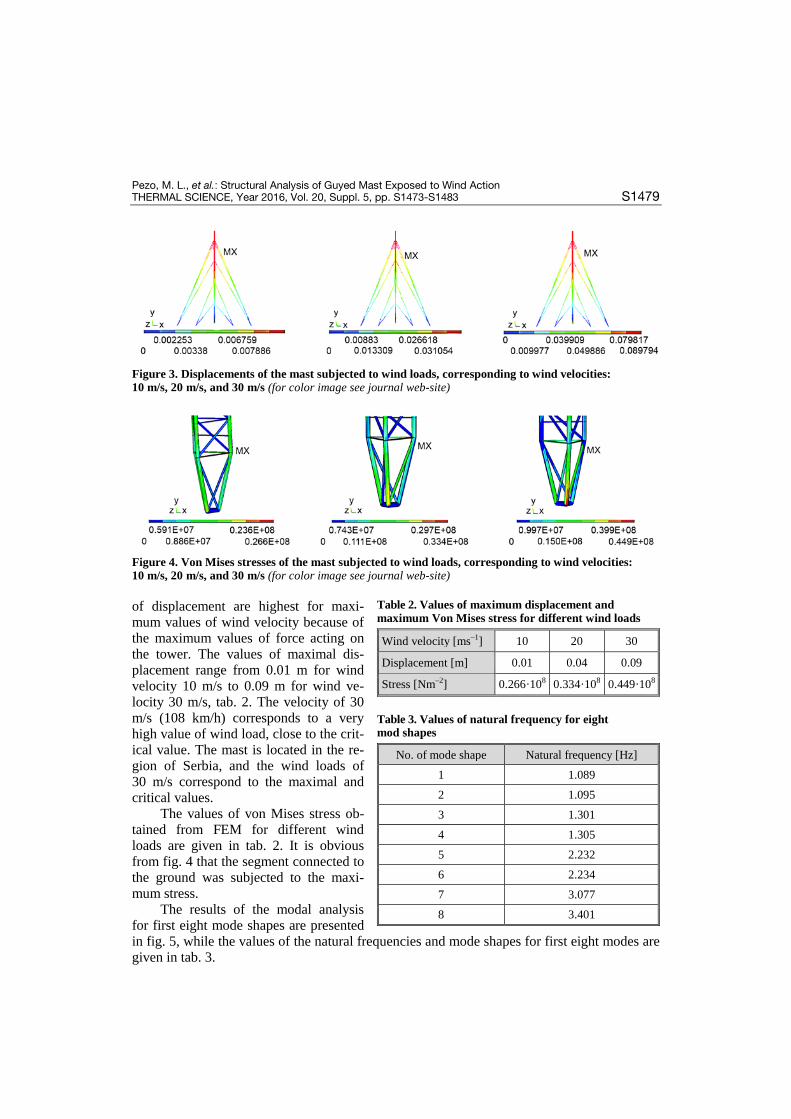
Figure 3. Displacements of the mast subjected to wind loads, corresponding to wind velocities: 10 m/s, 20 m/s, and 30 m/s (for color image see journal web-site)
Figure 4. Von Mises stresses of the mast subjected to wind loads, corresponding to wind velocities: 10 m/s, 20 m/s, and 30 m/s (for color image see journal web-site)
of displacement are highest for maxi-mum values of wind velocity because of the maximum values of force acting on the tower. The values of maximal dis-placement range from 0.01 m for wind velocity 10 m/s to 0.09 m for wind ve-locity 30 m/s, tab. 2. The velocity of 30 m/s (108 km/h) corresponds to a very high value of wind load, close to the crit-ical value. The mast is located in the re-gion of Serbia, and the wind loads of 30 m/s correspond to the maximal and critical values.
The values of von Mises stress ob-tained from FEM for different wind loads are given in tab. 2. It is obvious from fig. 4 that the segment connected to the ground was subjected to the maxi-mum stress.
The results of the modal analysis for first eight mode shapes are presented in fig. 5, while the values of the natural frequencies and mode shapes for first eight modes are given in tab. 3.
Table 2. Values of maximum displacement and maximum Von Mises stress for different wind loads
Wind velocity [ms–1] 10 20 30
Displacement [m] 0.01 0.04 0.09
Stress [Nm–2] 0.266·108 0.334·108 0.449·108
Table 3. Values of natural frequency for eight mod shapes
No. of mode shape Natural frequency [Hz]
1 1.089
2 1.095
3 1.301
4 1.305
5 2.232
6 2.234
7 3.077
8 3.401

Pezo, M. L., et al.: Structural Analysis of Guyed Mast Exposed to Wind Action S1480 THERMAL SCIENCE, Year 2016, Vol. 20, Suppl. 5, pp. S1473-S1483
Figure 5. The results of the 1st, 2nd, 3rd, 4th, 5th, 6th, 7th, and 8th mode shape for modal analysis (for color image see journal web-site)
The lowest natural frequency of the mast is 1.09 Hz. According to Holmes [32], tur-bulent wind energy is low for frequencies greater than 1.0 Hz. This means that the structure is not very sensitive to the aero elastic effects. From the 5th mode of initial structures the fre-quency of oscillation is increased. This trend continues, resulting in value of 3.401 Hz for the last 8th mode.
Also, in the 7th mode of the mast, there is torsion, and the maximum displacement al-ways occurs on a lattice tower structure, which are a critical aspect of the exploitation of the structure. The identification of the natural frequency structure does not determine the relative importance of each mode in determining the response of the inertial load. Identifying the im-portant modes becomes significantly difficult as the number of degrees of freedom of the model increases, which further complicates this task in the case of mast, because a large number of modes of oscillation occurs in the cables, which are in fact independent of the tower. Therefore, for this type of construction the modes of oscillation are significantly higher. This further em-
phasizes the importance of the modal analysis to determine the frequency of the load caused by the oscillation of the structure, which helps de-termine which parts of the structure will be sub-jected to vibration at certain frequencies.
The fundamental flexural frequency of structures according to standard [33] is approx-imately 1.11 Hz. This value corresponds to the natural frequency of the first mode obtained from FEM analysis, tab. 3. Vibrations can cause rapid development of fatigue.
Figure 6 presents the results of the buck-ling load analysis. Table 4 presents the first three buckling load factor values for the inves-tigated mast structures.
Figure 6. Buckling mode associated with the 1st critical load (λ01 = 4.702) 10 m/s, 20 m/s, and 30 m/s (for color image see journal web-site)

Pezo, M. L., et al.: Structural Analysis of Guyed Mast Exposed to Wind Action THERMAL SCIENCE, Year 2016, Vol. 20, Suppl. 5, pp. S1473-S1483 S1481
From tab. 4 it is clear that the critical value of buckling load factor is for the first buckling mode. From fig. 6 it can be concluded that the first buckling mode is related to deformed configurations with the maximum modal amplitudes located in bars in the middle of the tower. If rigid connections are used in the design model, higher buckling load values will be induced, overestimating the actual values, [14]. In our case, this assumption can also be a reason for higher buckling load values. The linear eigen-value buckling analysis predicts the theoretical buckling strength (the bifurcation point) of an ideal linear elastic structure. More realistic buckling load value can be obtained from the non--linear buckling analysis.
The results of the numerical simulations compared with the European standards
European standard EN 1993-3-1 describes the principles and application rules for the safety, serviceability and durability of the tower, mast and chimney steel structures, giving the information about the maximal allowable displacements and moments of the structure. Part 3-1 of the standard deal with towers and masts. The internal forces and moments are determined by using elastic global analysis according to [33]. The internal forces and moments may be deter-mined by the second-order analysis, taking into account the influence of the deformation of the structure. The connections should satisfy the requirements of full continuity, with rigid connec-tions according to [34]. These results are compared and analyzed in this paper.
The European standards EN 1993-3-1:2006 [1], and EN 1993-1-6:2007 [2] give some information about the masts structure definition, internal forces and moments determi-nation.
The maximum displacement of the top of the tower, according to above mention standards is 0.202 m, higher than the displacement for the maximum wind load assumed in the FEM analysis. According to [35], the lateral displacement of the top of the mast is several times higher, because of the simplified expression from the standards, which was proposed in [36].
According to European standards [1, 2], maximum von Mises stress for these kind of structures is 0.7·108 N/m2, 65% more than the value obtained from FEM analysis of the maximum wind load. This is expected since the standards are general, applicable for different geometries and structures, while FEM provides information about particular structure and op-erating conditions.
According to standards for stress values up to 0.71·108 N/m2, [1, 2] the fatigue life of guyed masts subjected to in-line vibrations only induced by gusty wind may be assumed to be greater than 50 years.
Conclusion
The results of structural analysis of a guyed mast exposed to wind action are pre-sented in this paper. The FEM was used for this purpose. The mast is modeled as tower 79 m height with four levels of guys and ground exposure. The finite element numerical model used for the static structural analysis includes wind loads obtained for three different wind ve-locities, 10 m/s, 20 m/s, and 30 m/s. Modal analysis was done in order to determine natural frequency and mode shapes of the structure. European standards EN 1993-3-1:2006 and EN 1993-1-6:2007 are used to analyze the structure of guyed mast and to calculate the internal
Table 4. Buckling load factor values
Number of buckling load factor
Value of buckling load factor
λ01 4.702
λ02 10.798
λ03 10.814

Pezo, M. L., et al.: Structural Analysis of Guyed Mast Exposed to Wind Action S1482 THERMAL SCIENCE, Year 2016, Vol. 20, Suppl. 5, pp. S1473-S1483
forces and moments for elastic structural analysis. The results of structural and modal analysis are compared with the results obtained using related equations described by standards and it can be concluded that the values of maximal displacements and moments are higher in the case of calculations based on standards. This was expected because the standards should pro-vide safety and reliability in the general case, for different geometries and operating condi-tions. But, for buckling analysis the critical value of buckling load factor overestimates the ac-tual values. The explanation for this phenomenon should be found in linear eigenvalue buck-ling analysis and definition of connections between the segment elements.
Acknowledgment
This work was supported by the Ministry of Education, Science and Technological Development of the Republic of Serbia grant TR33036.
Nomenclature A – reference area CD – drag coefficient [D] – elastic stiffness matrix E – Young's modulus F(y) – drag force
theF
– element thermal load vector preF
– element pressure vector acting on the areap
ndeF
– nodal forces applied to the element fi – projected components of the cable force i – Cartesian co-ordinate j – index of sub-element [Ke] – element stiffness matrix lj – length of cable jth element [Me] – element mass matrix [N] – matrix of finite element shape functions n – number of cable elements pk
i – load applied to kth node T j – table tension for jth sub-element
w – displacement within the element wi – uniformly distributed loads u – displacement vector ü – acceleration vector y – distance from the ground v – velocity of the wind
Greek symbols
α – wind velocity profiles factor ρ – density of the air σ – stress vector thσ – thermal strain vector
Subscript
D – drag E – element el – elastic th – thermal
Reference [1] ***, EN 1993-3-1:2006, Eurocode 3 – Design of steel structures – Part 3-1: Towers, masts and chimneys [2] ***, EN 1993-1-6:2007, Eurocode 3 – Design of steel structures – Part 1-6: Strength and Stability of
Shell Structures [3] Bazeos, N., et al., Static, Seismic and Stability Analyses of a Prototype Wind Turbine Steel Tower, En-
gineering Structures, 24 (2002), 8, pp. 1015-1025 [4] Harikrishna, P., et al., Full Scale Measurements of the Structural Response of a 50 m Guyed Mast under
Wind Loading, Engineering Structures, 25 (2003), 7, pp. 859-867 [5] Gioffre, M., et al., Removable Guyed Mast for Mobile Phone Networks: Wind Load Modeling and
Structural Response, Journal of Wind Engineering and Industrial Aerodynamics, 92 (2004), 6, pp. 463-475
[6] Bisht, R. S., Jain, A. K., Wind and Wave Induced Behavior of Offshore Guyed Tower Platforms, Ocean Engineering, 25 (1998), 7, pp. 501-519
[7] Ben Kahla, N., Dynamic Analysis of Guyed Towers, Engineering Structures, 16 (1994), 4, pp. 293-301 [8] Ben Kahla, N., Nonlinear Dynamic Response of a Guyed Tower to a Sudden Guy Rupture, Engineering
Structures, 19 (1997), 11, pp. 879-890 [9] Law, S. S., et al., Time-Varying Wind Load Identification from Structural Responses, Engineering
Structures, 27 (2005), 10, pp. 1586-1598

Pezo, M. L., et al.: Structural Analysis of Guyed Mast Exposed to Wind Action THERMAL SCIENCE, Year 2016, Vol. 20, Suppl. 5, pp. S1473-S1483 S1483
[10] Wahba, Y. M. F., et al., Evaluation of Non-Linear Analysis of Guyed Antenna Towers, Computers and Structures, 68 (1998), 1, pp. 207-212
[11] Saudi, G., Structural Assessment of a Guyed Mast Through Measurement of Natural frequencies, Engi-neering Structures, 59 (2014), Feb., pp. 104-112
[12] Battista, R. C. et al., Dynamic Behavior and Stability of Transmission Line Towers under Wind Forces, Journal of Wind Engineering and Industrial Aerodynamics, 91 (2003), 8, pp. 1051-1067
[13] Yan-Li, H., et al., Nonlinear Discrete Analysis Method for Random Vibration of Guyed Masts under Wind Load, Journal of Wind Engineering and Industrial Aerodynamics, 91 (2003), 4, pp. 513-525
[14] da Silva, J. G. S., et al., Structural Assessment of Current Steel Design Models for Transmission and Telecommunication Towers, Journal of Constructional Steel Research, 61 (2005), 8, pp. 1108-1134
[15] Gantes, C., et al., Modeling, Loading, and Preliminary Design Considerations for Tall Guyed Towers, Computers & Structures, 49 (1993), 5, pp. 797-805
[16] Irvine, H. M., Cable Structures, MIT Press, Cambridge, Mass., USA, 1981 [17] Hobbs, R. E., Raoof, M., Behaviour of Cables under Dynamic or Repeated Loading, J. Construct. Steel
Res., 39 (1996), 1, pp. 31-50 [18] Desai, Y. M., Punde, S., Simple Model for Dynamic Analysis of Cable Supported Structures, Engineer-
ing Structures, 23 (2001), 3, pp. 271-279 [19] Salehi, A. A. M., et al., Nonlinear Analysis of Cable Structures under General Loadings, Finite Elements
in Analysis and Design, 73 (2013), Oct., pp. 11-19 [20] Timoshenko, S. P., On the Correction Factor for Shear of the Differential Equation for Transverse Vibra-
tions of Bars of Uniform Cross-Section, Philosophical Magazine, 41 (1921), pp. 744-746 [21] Jayaraman, H. B., Knudsen, W. C., Curved Element for the Analysis of Cable Structures, Computers &
Structures, 14 (1981), 3-4, pp. 325-333 [22] Leonard, J. W., Nath, J. H., Comparison of Finite Element and Lumped Parameter Methods for Oceanic
Cables, Eng. Struct., 3 (1981), 3, pp. 153-167 [23] Macdonald, J. H. G., et al., Generalised Modal Stability of Inclined Cables Subjected to Support Excita-
tions, Journal of Sound and Vibration, 329 (2010), 21, pp. 4515-4533 [24] Fu, J. Y., et al., Full-Scale Measurements of Wind Effects on Guangzhou West Tower, Engineering
Structures, 35 (2012), Feb., pp. 120-139 [25] Davenport, A. G., Sparling, B. F., Dynamic Gust Response Factors for Guyed Towers, Journal of Wind
Engineering and Industrial Aerodynamics, 43 (1992), 1, pp. 2237-2248 [26] Hansen, S. O., Krenk, S., Dynamic Along-Wind Response of Simple Structures, Journal of Wind Engi-
neering and Industrial Aerodynamics, 82 (1999), 1, pp. 147-171 [27] Venanzi, I., et al., Robust and Reliable Optimization of Wind-Excited Cable-Stayed Masts, Journal of
Wind Engineering and Industrial Aerodynamics, 147 (2015), Dec., pp. 368-379 [28] Hamada, A., El Damatty, A. A., Behaviour of Guyed Transmission Line Structures under Tornado Wind
Loading, Computers and Structures, 89 (2011), 11, pp. 986-1003 [29] Pezo, M., Bakić, V., Numerical Determination of Drag Coefficient for Guyed Mast Exposed to Wind
Action, Engineering Structures, 62-63 (2014), March, pp. 98-104 [30] Balczo, M., et al., Prediction of Wind Load Acting on Telecommunication Masts, Proceedings, IABSE
2006 Annual Meetings and Symposium, Budapest, Hungary, 2006 [31] Rajakumar, C., Rogers, C. R., The Lanczos Algorithm Applied to Unsymmetric Generalized Eigenvalue
Problem, International Journal for Numerical Methods in Engineering, 32 (1992), 5, pp. 1009-1026 [32] Holmes, J. D., Recent Developments in the Specification of Wind Loads on Transmission Lines, Journal
of Wind and Engineering, 5 (2008), 1, pp. 8-18 [33] ***, EN 1993-1-1 (2005): Eurocode 3: Design of steel structures – Part 1-1: General rules [34] ***, EN 1993-1-8 (2005): Eurocode 3: Design of steel structures – Part 1-8: Design of joints [35] ***, EN 1991-1-4 (2005): Eurocode 1: Actions on structures – Part 1-4: General actions – Wind actions [36] Belevičius, R., et al., Optimization of Tall Guyed Masts Using Genetic algorithms, Engineering Structu-
res, 56 (2013), Nov., pp. 239-245
Paper submitted: April 7, 2016 Paper revised: October 7, 2016 Paper accepted: October 17, 2016
