structural assessment design brief
TRANSCRIPT

Hamilton Rapid Transit Preliminary Design and Feasibility Study
B-LINE
STRUCTURAL ASSESSMENT DESIGN BRIEFVersion:1.0

November 2011
Hamilton Rapid Transit Preliminary Design and Feasibility Study
B-LINE
STRUCTURAL ASSESSMENT DESIGN BRIEFVersion:1.0

Hamilton LRT Structural Assessment Report
Table of Contents
1.0 INTRODUCTION ............................................................................................................... 2 2.0 PROPOSED RETAINING WALL ALONG NORTH SIDE OF PROPOSED LRT BRIDGE
OVER HIGHWAY 403 ....................................................................................................... 2 2.1 RECOMMENDATIONS ..................................................................................................... 2
3.0 PROPOSED RETAINING WALL ALONG SOUTH SIDE OF PROPOSED LRT BRIDGE OVER HIGHWAY 403 ....................................................................................................... 5
4.0 EXISTING CP OVERPASS ON KING STREET WEST EAST OF DUNDURN STREET . 8 4.1 EXISTING CONDITION .................................................................................................... 8
4.2 RECOMMENDATIONS ..................................................................................................... 8
5.0 EXISTING OVERHEAD PEDESTRIAN WALKWAY ACROSS KING STREET WEST AT SUMMERS LANE ..................................................................................................... 11
5.1 EXISTING CONDITION .................................................................................................. 11
5.2 ACCOMMODATION OF THE LRT UNDER THE PEDESTRIAN BRIDGE ..................... 11
5.3 RECOMMENDATIONS ................................................................................................... 11
6.0 EXISTING VEHICULAR TUNNEL AT THE MCNAB TRANSIT TERMINAL ................. 15 6.1 EXISTING CONDITION .................................................................................................. 15
6.2 RECOMMENDATIONS ................................................................................................... 15
7.0 PROPOSED RETAINING WALL ALONG SOUTH SIDE OF QUEENSTON ROAD, WEST OF RED HILL VALLEY ....................................................................................... 21
7.1 EXISTING CONDITION .................................................................................................. 21
7.2 EVALUATED OPTIONS .................................................................................................. 21
7.3 CONCLUSION ................................................................................................................ 23
DISCLAIMER .............................................................................................................................. 24
File: Structural Assessment Report November 4th 2011.doc © 2011 SNC‐Lavalin Inc. All rights reserved –i– Confidential

Hamilton LRT Structural Assessment Report
1.0 Introduction Through the preliminary design of the B-Line, it was determined that a structural assessment of seven structures along the alignment is needed to determine the extent of modifications, if any, that may be required to accommodate the LRT. These structures are the following:
1) A proposed retaining wall along the north side of the proposed LRT bridge over Highway 403 joining the west abutment (Station 2+000);
2) The proposed LRT bridge over Highway 403 (Station 2+015 to Station 2+327);
3) A proposed retaining wall along the south side of the proposed LRT bridge over Highway 403 joining the east abutment (Station 2+332);
4) The existing CP overpass on King Street West east of Dundurn Street (Station 2+410);
5) The existing overhead pedestrian walkway across King Street West at Summer’s Lane (Station 4+086);
6) The existing vehicular tunnel under King Street West at the McNab bus terminal (Station 4+189);
7) The existing Queenston Road bridge over the Red Hill Valley Parkway (Station 11+844 to Station 11+951)
8) A proposed retaining wall along south side of Queenston Road, west of Red Hill Valley (Station 11+612 to Station 11+683)
The proposed bridge over Highway 403 (item 2) and the existing bridge over the Red Hill Valley Parkway (item 7) have undergone individual structural assessments under separate covers and will not be included in the assessment herein.
2.0 Proposed retaining wall along north side of proposed LRT bridge over Highway 403
The proposed bridge over Highway 403 is south of a parking lot which is susceptible to spill of the fill from under the LRT bridge. The purpose of the retaining wall is to contain the fill under the guideway as well as protect one existing mature tree (See Figures 1 and 2).
The retaining wall will be approximately 35 m long and the height will vary between 4 m and 1.5 m.
The construction cost of the retaining wall will be approximately $ 175,000, which could be substantially reduced if the fill is allowed to spill on to the existing parking lot, resulting in a loss of some parking spaces. In order to help balance the impact, the parking lot may be expanded to the southwest to compensate for the lost spaces.
2.1 Recommendations It is recommended that the feasibility of reconfiguring the parking lot in order to avoid the construction of a full retaining wall and avoid any potential impacts on the mature tree be assessed by the City of Hamilton in the next design stage.
If reconfiguring the parking lot is not feasible and a retaining wall must be installed, further detailed design of the retaining wall in order to protect the mature tree must be undertaken in the next design phase.
This can be accompanied by a cost benefit analysis of both options prior to the detailed design phase.
File: Structural Assessment Report November 4th 2011.doc © 2011 SNC‐Lavalin Inc. All rights reserved –2– Confidential


Hamilton LRT Structural Assessment Report
3.0 Proposed retaining wall along south side of proposed LRT bridge over Highway 403
The proposed wing wall of the bridge abutment will be an extended wing wall from the LRT bridge abutment (See Figures 3 and 4). It is needed to protect the existing asphalt path along the valley and to protect some mature trees to the south.
The retaining wall will be approximately be 12 m long and will vary in height between 4.5 m and 1.5 m.
The construction cost of the retaining wall will approximately be $ 95,000.
File: Structural Assessment Report November 4th 2011.doc © 2011 SNC‐Lavalin Inc. All rights reserved –5– Confidential


Figure 4: Proposed South Retaining Wall at East Side of Proposed LRT Bridge over Highway 403 - Cross-Section
KingStreetWest

Hamilton LRT Structural Assessment Report
4.0 Existing CP overpass on King Street West east of Dundurn Street
4.1 Existing Condition The existing overpass structure consists of steel I-beam girders spanning over two CP rail tracks with an opening of 9 m. The total width of the overpass is approximately 27.5 m, which includes two 1.8 m sidewalks and a 23.8 m roadway. Twelve steel girders with a height of 960 mm support the reinforced concrete slab with a distance from centre to centre of 2.3 m. The combined thickness of the concrete slab and asphalt pavement is 1200 mm (See Figure 5).
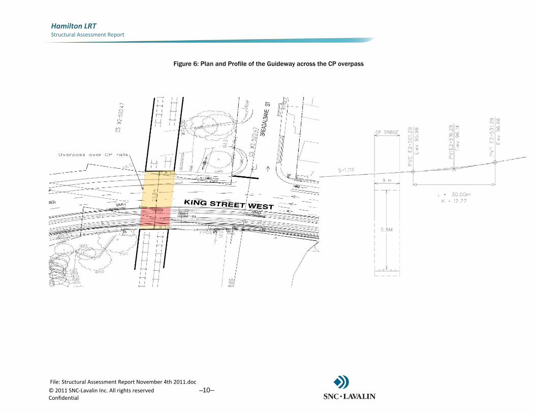
4.2 Recommendations The guideway will occupy 8 m of the overpass, occupying two traffic lanes on the south side (See Figure 6). The structural assessment confirmed that the existing structure with five girders directly under the guideway was sufficient to carry the additional load of the guideway and the LRT vehicles.
The rails will be fixed to the existing reinforced concrete slab and an additional concrete pour will embed the grooved rails. Although the thickness of the reinforced slab is not known at this preliminary assessment phase, it will need to be determined in the detailed design phase in order to define the design detail of the rail fixation to the slab. If possible, the guideway should be flushed with the pavement. If a height difference must be tolerated, the guideway should become level with the pavement within the available 20 m before the next side entrance to the south.
File: Structural Assessment Report November 4th 2011.doc © 2011 SNC‐Lavalin Inc. All rights reserved –8– Confidential

File: Structural Assessment Report November 4th 2011.doc © 2011 SNC‐Lavalin Inc. All rights reserved –9– Confidential
Hamilton LRT Structural Assessment Report
Figure 5: CP Overpass east of King and Dundurn
Hamilton LRT Structural Assessment Report
Figure 6: Plan and Profile of the Guideway across the CP overpass
File: Structural Assessment Report November 4th 2011.doc © 2011 SNC‐Lavalin Inc. All rights reserved –10– Confidential

Hamilton LRT Structural Assessment Report
5.0 Existing overhead pedestrian walkway across King Street West at Summers Lane
5.1 Existing Condition There is an enclosed steel walkway over King Street West at Summers Lane, between Bay and McNab Street (See Figures 7 and 8). The walkway spans the entire length of the street, which is 26 m and has a width of 6 m.
The clearance under the walkway is only 4.2 m, which is considered substandard. There have been recorded incidents of tractor-trailers scraping the underside of the bridge. With the addition of the LRT, this becomes an even greater concern as the clearance will be further diminished due to the addition of a catenary contact wire attachment to the underside of the bridge. Damage to the supports of the contact wire may cause short circuiting between the 750 V live wires and the steel structure, possibly endangering pedestrians both on the walkway and on the sidewalks.
5.2 Accommodation of the LRT under the pedestrian bridge The LRT contact wires can be affixed to the underside of the walkway either using a cross I-beam and clamps or by using a steady arm (See Figure 9). The minimum operating height of the pantograph is approximately 4 m, leaving only 200 mm for clearance.
While it is possible to accommodate the LRT under the existing bridge, and this condition can be further examined in the detailed design phase, the City of Hamilton must carefully review the risk of truck impacts to the underside of the walkway resulting in possible damage to the contact wire supports.
5.3 Recommendations Due to the possible safety risk as a result of substandard clearance under the walkway, it is recommended that the City of Hamilton assess the feasibility of removing the bridge prior to the construction of the B-Line. The City should consult with the relevant stakeholders, particularly the Convention Centre and the Sheraton Hotel, as well as study the usage of the walkway.
If the walkway is deemed necessary, the feasibility of raising the pedestrian bridge to comply with the recommended clearance of 5.3m to the underside of the bridge should be investigated. The raised walkway can be partially accommodated by ramps/stairs which can be constructed over the sidewalks on either side of the bridge. A safe attachment of contact wires to the underside with sufficient insulation should be included in the redesign for the reconfiguration of the raised structure.
File: Structural Assessment Report November 4th 2011.doc © 2011 SNC‐Lavalin Inc. All rights reserved –11– Confidential

File: Structural Assessment Report November 4th 2011.doc © 2011 SNC‐Lavalin Inc. All rights reserved –12– Confidential
Hamilton LRT Structural Assessment Report
Figure 7: Pedestrian Walkway over King St West between McNab and Bay St.

Hamilton LRT Structural Assessment Report
Figure 8: Plan and Profile of Pedestrian Walkway over King Street
File: Structural Assessment Report November 4th 2011.doc © 2011 SNC‐Lavalin Inc. All rights reserved –13– Confidential

Hamilton LRT Structural Assessment Report
Figure 9: Detail of possible attachment of contact wire to Pedestrian Walkway underside using I-beams and clamps
File: Structural Assessment Report November 4th 2011.doc © 2011 SNC‐Lavalin Inc. All rights reserved –14– Confidential

Hamilton LRT Structural Assessment Report
6.0 Existing Vehicular Tunnel at The McNab Transit Terminal
6.1 Existing Condition The tunnel is located under King Street West along McNab Street and links two vehicular lanes with the underground access to the McNab Transit Terminal. The tunnel has a total width of 8.5 m and has a vertical clearance of 4.4 m (See Figures 10 and 11). The minimum burden thickness is 1.14 m. The LRT profile along King Street West is shown in Figure 12.
6.2 Recommendations The structural assessment confirmed that the tunnel structure can accommodate the additional loads from the guideway and the LRT vehicles. The 1.14 m burden thickness allows for the guideway to be flushed without any structural constraints (See Figures 13 and 14).
It is recommended to apply floating trackwork structures across the tunnel to avoid transfer of vibration to the tunnel roof and to the adjacent buildings.
Special measures to avoid damage to the tunnel cover slab during construction and to maintain the current level of waterproofing to the tunnel need to be developed in the detailed design phase.
File: Structural Assessment Report November 4th 2011.doc © 2011 SNC‐Lavalin Inc. All rights reserved –15– Confidential

Hamilton LRT Structural Assessment Report
Figure 10: Vehicular tunnel under King Street at McNab Transit Terminal
File: Structural Assessment Report November 4th 2011.doc © 2011 SNC‐Lavalin Inc. All rights reserved –16– Confidential

Hamilton LRT Structural Assessment Report
Figure 11: Plan view of Vehicular Tunnel under King Street
File: Structural Assessment Report November 4th 2011.doc © 2011 SNC‐Lavalin Inc. All rights reserved –17– Confidential

Hamilton LRT Structural Assessment Report
Figure 12: Profile of LRT guideway over existing Vehicular Tunnel under King Street
File: Structural Assessment Report November 4th 2011.doc © 2011 SNC‐Lavalin Inc. All rights reserved –18– Confidential


Hamilton LRT Structural Assessment Report
7.0 Proposed retaining wall along south side of Queenston Road, West of Red Hill Valley
7.1 Existing Condition In the section between Station E11+680 to Station E11+773 near the Red Hill Valley Bridge, the road alignment as a negative slope to the east towards the bridge. Currently there are retaining walls on the north side adjacent to an apartment building and on the south side towards the Red Hill Valley Bridge. The introduction of the B-Line LRT requires road widening.
Therefore, it is necessary to implement a retaining wall structure on the south side, just west of Station E11+680.
Below are three options evaluated for the new retaining wall, along with a recommendation of the preferred option.
7.2 Evaluated Options The structural assessment of the adjoining area confirmed that a new retaining wall should be constructed just west of the existing retaining wall on the south side, and will have an approximate length of 68 m.
Three options were evaluated for the type of retaining wall construction:
• Option A - A cantilever wall that is reverse T-shaped;
• Option B – A cantilever wall that is L shaped;
• Options C – A wall that is fixed using soil nails.
Option A: Option A is a reverse T-shaped cantilever wall as shown in the figure below. The wall will have a maximum height of 2.7 m and a maximum width of footing will be 3.2m. The wall thickness will be 0.4m. The advantage of this option is that it uses less concrete and rebar than Option B. The disadvantage of this option is that it will require more backfill compared to Option B, as well as it requires excavation near the property line, although it is not expected that the construction of the retaining wall will compromise the structural integrity of the building, as it is assumed the dwelling has a basement. The impacts to property can be minimized if adequate construction staging methods are developed during the detail design phase. As the footing only extends slightly towards the guideway, there is still adequate room for the construction of a catch basin.
File: Structural Assessment Report November 4th 2011.doc © 2011 SNC‐Lavalin Inc. All rights reserved –21– Confidential

Hamilton LRT Structural Assessment Report
Figure 13: Option A Cantilever reverse T-shaped Retaining Wall
Option B: Option B is an L-shaped cantilever wall as shown in the figure below. The maximum height of the wall measures 2.7 m. The maximum footing width is 3.6m, with a constant wall thickness of 0.4m. The advantage of this option is that it requires less excavation towards the property line than Option A. The disadvantage of this option is that it requires more concrete and rebar than Option A. Also, the footing extends towards the road which implies that more road construction would be required in comparison to the other two options. Additionally, the proximity of the footing to the road surface near the curb locations could negatively impact the placement of required catch basins and leads.
Figure 14: Option B Cantilever L-shaped Retaining Wall
File: Structural Assessment Report November 4th 2011.doc © 2011 SNC‐Lavalin Inc. All rights reserved –22– Confidential

Hamilton LRT Structural Assessment Report
Option C: Option C is a retaining wall that is fixed using stabilizing soil nails. The advantage of this option is that it is the most economical option in terms of concrete and rebar quantities. The disadvantage is the nails encroach on to the property, which may require property acquisition, potentially resulting in an additional cost.
Figure 15: Option C Retaining Wall fixed with Soil Nails
7.3 Conclusion Based on the above listed advantages and disadvantages of the three options, it has been determined that Option A should be further evaluated in the detailed design phase. A plan view of the proposed option A is shown in Figure 16 below.
File: Structural Assessment Report November 4th 2011.doc © 2011 SNC‐Lavalin Inc. All rights reserved –23– Confidential


File: Structural Assessment Report November 4th 2011.doc © 2011 SNC‐Lavalin Inc. All rights reserved –24– Confidential
Hamilton LRT Structural Assessment Report
Disclaimer This document contains the expression of the professional opinion of Steer Davies Gleave North America Inc. (“SDG”) as to the matters set out herein, using its professional judgment and reasonable care. It is to be read in the context of the agreement (the “Agreement”) between SDG and the City of Hamilton (the “Client”) for the Rapid Transit Preliminary Design and Feasibility Study (reference C11-12-10), and the methodology, procedures and techniques used, SDG’s assumptions, and the circumstances and constrains under which its mandate was performed. This document is written solely for the purpose stated in the Agreement, and for the sole and exclusive benefit of the Client, whose remedies are limited to those set out in the Agreement. This document is meant to be read as a whole, and sections or parts thereof should thus not be read or relied upon out of context.
SDG has, in preparing the Agreement outputs, followed methodology and procedures, and exercised due care consistent with the intended level of accuracy, using its professional judgment and reasonable care.
However, no warranty should be implied as to the accuracy of the Agreement outputs, forecasts and estimates. This analysis is based on data supplied by the client/collected by third parties. This has been checked whenever possible, however SDG cannot guarantee the accuracy of such data and does not take responsibility for estimates in so far as they are based on such data.
SDG disclaims any liability to the Client and to third parties in respect of the publication, reference, quoting, or distribution of this report or any of its contents to and reliance thereon by any third party.
DOCUMENT END