structural concrete systems
TRANSCRIPT

10-1
10Structural Concrete
Systems
Scott W. McConnell, P.E.*
10.1 Overview ............................................................................10-2Introduction • Durability • Constructability • Appearance
10.2 Building Loads...................................................................10-3Introduction • Gravity Live Loads • Lateral Live Loads
10.3 Composite Steel–Concrete Construction ........................10-7Introduction • Advantages and Disadvantages • Other Considerations • Composite Action • Unshored vs. Shored Construction • Composite Columns
10.4 Foundations .....................................................................10-10Shallow Foundations • Deep Foundations
10.5 Structural Frames............................................................10-14Rigid Frames • Braced and Unbraced Frames • Column Proportioning • Beam Proportioning • Beam–Column Joints • Construction Considerations
10.6 Concrete Slab and Plate Systems....................................10-17One-Way Beam–Slab Systems • Flat Plates and Flat Slabs
10.7 Liquid-Containing Structures ........................................10-23Introduction • Circular Tanks • Rectangular Tanks
10.8 Mass Concrete .................................................................10-26Introduction • Materials for Mass Concrete • Concrete Mixture Design • Quality Control
10.9 On-Site Precasting and Tilt-Up Construction ..............10-2810.10 Lift-Slab Construction ....................................................10-30
Introduction • Foundations • Columns • Supported Slabs • Lifting Collars • Lifting Jacks • Critical Component Design • Applications
10.11 Slip-Form Construction .................................................10-33Introduction • Materials and Methods • Advantages and Disadvantages • Economy
10.12 Prestressed Concrete .......................................................10-37Introduction • Pretensioned (Precast) Concrete • Post-Tensioned Concrete
Acknowledgments......................................................................10-40References ...................................................................................10-40
* Principal and Director, Structural Department of CMX (formerly Schoor DePalma, Engineers and Consultants),Manalapan, New Jersey; registered engineer in several states and practicing engineering for more than 15 years.
© 2008 by Taylor & Francis Group, LLC

10-2 Concrete Construction Engineering Handbook
10.1 Overview
10.1.1 Introduction
Concrete structural systems must be durable, constructable, economical, and functional. The systemselected must be strong and in many cases aesthetically pleasing. The system must have deflections thatare within acceptable limits and, in seismic areas, must have the ability to absorb the large amounts ofenergy generated by seismic events. Selection of a structural system can sometimes be a difficult process.In many cases, structural steel is the more economical system to use. In general, when the system is tobe hidden by architectural finishes, concrete systems are not the systems of choice. When the structureitself becomes an architectural expression, concrete is often the material of choice. In most cases, theformwork for the concrete system selected represents almost half of the total expense of the structure.Obviously, repetitive systems that reduce the cost of formwork relative to the cost of the concrete andreinforcing are candidates for concrete systems. In fact, under certain conditions concrete systems maybe the structural systems of choice, even when the concrete is not exposed or architectural. The plasticnature of the material provides an effective structural solution to any unusual requirements. In suchcases, structural steel systems cannot provide the freedom of design that concrete provides.
10.1.2 Durability
Properly proportioned concrete, when placed, finished, and cured in accordance with established stan-dards, provides a durability that is virtually maintenance free and seldom matched by structural steelsystems. The weathering steels, often used in bridge design, are the closest rivals to a good dense concretewith proper air entrainment. The problems associated with rust staining have largely limited the use ofsteel structural systems to bridge structures. The durability of concrete is directly related to the qualityof the concrete. Dense, well-consolidated concrete with a low water/cement ratio and proper amountsof entrained air will be durable in all but the most hostile environments. Varying cement types, additives,and surface treatments are effective in extending the durability of concrete subjected to less than desirableconditions.
10.1.3 Constructability
The choice of the structural system must be based on the availability of skilled labor to accomplish thedesign requirements. Concrete construction, unlike steel, is somewhat regional with respect to acceptedand common practices. For example, the use of high-strength concrete (fc′ in excess of 5000 psi) is moreprevalent in metropolitan areas of the United States. Experience with the construction of ductile momentframes is more widespread in geographic areas traditionally considered to be seismically active. Bridges,highways, water treatment facilities, and buildings each have their own special sets of design requirements,specialized techniques, and selection of materials developed to address these needs. Localized laborpractices and costs have a major influence on the degree to which concrete structural systems are utilized.Cast-in-place concrete is considerably more labor intensive than the fabrication of precast concrete.Conversely, transportation and erection of precast systems are obviously more expensive than those ofcast-in-place systems. In theory, the optimum reinforcement for reinforced concrete would be anextremely large number of very small reinforcing bars to provide a uniform distribution of tensilereinforcing. The reality is that one is forced to use the least number of reinforcing bars and to use largebars to keep the labor costs within reason. Local union agreements, in many cases, place restrictions onwhich bars may be cut and fabricated in the field vs. which may be shop cut and fabricated. Obviously,shop fabrication is more desirable, because the equipment available and the controlled work environmentgenerally result in a better product.
The cost of formwork constitutes a major portion of the cost of concrete structures. It is not uncommonfor the cost of the formwork to represent 50% of the total cost of the in-place concrete. Systems thatrequire simple, straightforward, reusable forms have a significant cost advantage over systems requiring
© 2008 by Taylor & Francis Group, LLC

Structural Concrete Systems 10-3
more complex forms. Many times the effort to reduce the complexity of formwork leads to simplerconfigurations that, unfortunately, require additional concrete along with additional loads, which mustbe carried by the foundation system. Whenever formwork can be reused, more complex configurationscan be utilized. The ability to quickly strip and re-erect forms is a major cost savings in that overallconstruction time and general condition-related costs are reduced. For a structure under construction,the use of concrete or masonry usually results in the greatest time exposure to the elements. Given thissignificant length of exposure, the geographic location and the time of year that construction takes placecan have a major impact on the costs of concrete construction. Obviously, some steps can be taken toallow concreting operations to continue during weather extremes, but this invariably results in additionaljob costs. An added concern during periods of weather extremes is quality control.
10.1.4 Appearance
In many cases, concrete is called upon to perform several functions. In addition to providing strengthfor a structure, it also acts as cladding, it must be durable and weather resistant, and it must have apleasing appearance. The design of the exposed finish may require a simple rubbed surface to removeminor surface blemishes and form marks or a considerably more expensive architectural surface finish.Great care must be taken to successfully achieve consistent architectural finishes. Elements that must beconsidered include:
• A workable concrete mix to facilitate placing and finishing activities• Consistent, controlled water content in the mix• Use of cement from a single batch, as ASTM C 150 allows for a wide variation in the coarseness
and thus color of the cement powder• Accurate batching of the components of the cement• Leak-free formwork to eliminate bleed marks due to loss of paste• Proper placing techniques to avoid segregation of the mix and cold joints• Consideration of varying weather conditions• Proper curing• Careful formwork removal• Protection of the concrete from damage and staining during subsequent construction operations
Failure to successfully accomplish all of the above will almost certainly lead to less than satisfactoryfinishes, placing the designer and owner in the unenviable position of deciding to accept blemishedconcrete or delaying the project while the defective concrete is removed and replaced. Repaired honey-combing of exposed surfaces invariably deteriorates with time (at least with respect to appearance) andis a major contributor to unsightly concrete. In some instances, surface coatings are the only way toobtain an acceptable surface finish. Structural concrete not required to meet the visual requirements ofarchitectural concrete must nevertheless be durable and weather resistant. The placing and curing require-ments above should still be required. The color variations resulting from use of cement from varyingbatches and manufacturers and some relaxation of moisture control may be acceptable for the application.
10.2 Building Loads
10.2.1 Introduction
Design loads dictated by model building codes reflect the statistically probable maximum loads that canbe expected to act upon a structural system. These loads are typically quoted as service loads, meaningthat they have not been factored upward. Load factors are employed to account for inconsistencies inmaterial properties, construction and fabrication practices, and the predictability of the load itself. Theyare, in essence, safety factors. In addition, load factors are employed to conduct analysis of the structuralsystem in the ultimate stress range, as opposed to the service stress range.
© 2008 by Taylor & Francis Group, LLC

10-4 Concrete Construction Engineering Handbook
Typically, the yield point of commonly used construction materials, such as steel and concrete, is wellestablished; therefore, it is possible to design to the ultimate performance range of these materials. It isnot desirable, however, to design structures so they perform in the ultimate range under typical loadingconditions. This would not leave a sufficient factor of safety in the event of anomalies in the designassumptions. For this reason, the service loads quoted by the model building codes are intended to beapplied to materials within their elastic stress ranges. If the designer wishes to analyze a structure byconsidering the ultimate performance of the materials, then load factors must be applied to the serviceloads.
As noted above, load factors are the product of both materials analysis and probabilistic theoryconcerning the construction and fabrication processes. Concrete design per ACI 318-05 employs loadfactors of 1.2 for dead loads and 1.6 for live loads acting simultaneously. Other combinations of loadfactors are employed depending on the code being used and the effect of one or more loads being appliedat the same time. The distinction between these values is primarily based on the lack of predictability ofhow live loads will be applied to a structure. How to classify a dead load and a live load is a question tobe addressed by the designer; however, certain truisms should be considered.
Material weights are generally predictable and can be specifically calculated as they apply to a givenstructural member. The weights of large, immoveable objects, such as mechanical equipment, permanentshelving or storage racks, or planters are also fairly predictable. These elements can be classified as deadloads with little risk of inaccuracy.
Human occupancy, furniture, and transient storage that fluctuate in volume and intensity are amongthe items that are less predictable and thus subject to a higher load factor. In addition, external loadsthat act on structures are equally unpredictable. Wind, seismic, hydrostatic, and earth loads must befactored as live loads to consider their inherent unpredictable nature.
Maximum load combinations, such as live plus dead plus wind, have the statistical tendency to occurso infrequently that the various model building codes and material-design manuals permit reductionsin the overall load applied to the structural system. The reduction factors differ according to the codesand manuals, so the designer should check the applicable references for the particular project.
Model building codes determine the load factor combinations that must be used. Individual jurisdic-tions must adopt the provisions of a model building code for it to be the governing code. Jurisdictionsmight consist of municipalities, counties, or whole states. Jurisdictions may adopt only certain provisionsof a model code and not others. They might supplement the model code with additional design infor-mation that is specifically applicable to a given region.
The designer is cautioned to fully understand the applicable building code where his or her project isto be built. It is the location of the structure that dictates the governing code, not the location of thedesigner, client, or reviewing agency. The designer must also be aware of local provisions that supersedethe model code; for example, municipalities located close to hurricane zones may adopt more stringentwind loads than are dictated by the adopted model code.
Finally, third-party sources assemble construction data pertaining to loads and material performance.These resources, such as Factory Mutual and Underwriters Laboratories, often develop their data to assistinsurance companies in establishing rate structures for coverage. As such, they tend to be slightly moreconservative in their statement of loads than the model building codes. The designer is obligated to followthese design guidelines only if the jurisdiction has adopted them into the local building code or if thebuilding owner, for whom the designer is producing the design, dictates that the more stringent designstandard be used. If these resources are used, specific attention should be paid to the treatment of snowand wind loading and to the fire rating of structural assemblies.
The most frequently referenced model building code in the United States is the International BuildingCode (IBC), which is used by 47 states and Washington, D.C. Adopted code editions and supplementsmight vary with each jurisdiction. It is incumbent on the designer to make certain which model codeand what code amendments and provisions have been adopted for the location of the project. For thepurposes of the following discussion, the IBC 2006 edition is referenced.
© 2008 by Taylor & Francis Group, LLC

Structural Concrete Systems 10-5
10.2.2 Gravity Live LoadsAnalytically, design loads can be divided into two primary groups: gravity loads, which predominantlyact vertically on the structure, and lateral loads, which predominantly act horizontally on the structure.Gravity loads account for all dead loads and those live loads associated with occupancy of the structure.The designer can refer to several sources for information to provide weight data regarding various buildingmaterials. Manufacturers provide tabulated load data for proprietary building materials. Nonproprietarymaterial weights, such as concrete, asphalt, and roofing and flooring materials, can be found in theAmerican Society of Civil Engineers’ publication ASCE 7 (Minimum Design Loads for Buildings and OtherStructures, Tables C3-1 and C3-2). Live-load data are developed with respect to the use and occupancyof a given structure. IBC Chapter 16, Section 1607, is devoted to establishing the intensity of various liveloads as they relate to various uses and types of structures. IBC Tables 1607.1 and 1607.6 provide abreakdown of the maximum anticipated design live loads for a wide variety of use conditions. Thedesigner should refer to these tables and the subsections of Section 1607 to establish the design live loadfor the use that most closely matches the anticipated use of the given structure. Local building codes donot generally permit interpolation between specified live loads; therefore, larger, multiuse facilities mayrequire subdivision into several analytical pieces for design purposes. It is both permissible and recom-mended that different live loads be applied to the structural model, as required to satisfy the variety ofintended uses. An example of this is the application of a 100-psf load near public means of exit, althoughthe remainder of the building requires only a 50-psf live load to satisfy an office-use criteria. The designeris reminded that the IBC live load data for use and occupancy are quoted as service loads. Appropriateload factors must be applied to permit analysis of the ultimate material stress range.
10.2.3 Lateral Live LoadsThe second group of live loads that must be considered by the designer are lateral loads, which are frequentlythe least predictable live loads. Such loads include wind, seismic, hydrostatic, and earth loads. Per IBC 2006,wind loads are determined in accordance with Chapter 6 of ASCE 7. The designer must first establish theapplicable basic wind speed for the locale of the given structure. The basic wind speed is defined as thefastest 3-second gust speed in miles per hour for a given locale associated with an annual probability of0.02 (50-year mean recurrence interval) and measured at a point 33 feet above the ground in Exposure C.The next design task is to determine the applicable exposure for the given structure. The exposure classifi-cations differentiate between sites that are subjected to high, direct wind forces due to terrain characteristicsand those that do not experience such wind forces due to shielding effects, building or forest density, orother terrain irregularities. Because subsequent adjustment factors are determined based on the exposureclassification, it is crucial that the designer make a thoughtful selection. The designer is cautioned that windforces are notoriously unpredictable. Large, concentrated forces can accumulate due to irregular buildinggeometry or aerodynamic effects around canopies, roofs, balconies, or multiple-story structures. Conse-quently, it is not recommended that liberties be taken with the exposure classification in an attempt torefine the load analysis. The most prominent physical features of the terrain, surrounding buildings, thegiven structure, and potential changes over the life span of the structure should be considered when selectingthe exposure group. The design wind pressure is determined by applying several modification factors tothe basic wind pressure. These factors consider gust effects, the windward or leeward face of the building,the type of structure involved, and the slope of the roof. Special factors are provided for chimney, tower,sign, and flagpole structures. When determining the wind force on an entire structure, the designer isreminded that the combination of both windward and leeward forces must be considered. ASCE 7 distin-guishes between main wind force-resisting systems and components and cladding. This distinction is basedon the acknowledgment that, although the combination of windward and leeward forces acts only upon aprimary system, components often experience intense concentrated forces due to surface irregularities ofthe building. Consequently, determining forces and gusts acting on components requires that the designerconsider both the size and the position of the component in question relative to the entire building.
© 2008 by Taylor & Francis Group, LLC

10-6 Concrete Construction Engineering Handbook
In practical application, buildings with multiple roof heights and articulated facades often require thedevelopment of a wind-pressure chart superimposed over each elevation of the building. This exercisepermits the designer to account for major component features on the building exterior. In addition,because the design industry has moved progressively further away from requiring individual structuralengineering consultants to shoulder the entire design responsibility for all building components, thedevelopment of a wind-force chart by the primary structural engineer provides appropriate informationfor subconsultants to design cladding systems and canopies.
Application of wind loads to a structural model is generally considered to occur at the slab–columnjoints for each floor level. This mode of application addresses the usual facade configuration in which thecladding is connected to the structure at each floor diaphragm. Where the facade treatment attaches to thestructure in a different fashion, the designer must follow the load path from the cladding to the framingto determine the most accurate mode of application of wind loads. The designer is reminded that the wind-load data provided in the IBC and ASCE 7 are service loads and must be factored upward by the appropriateload factor in order to work in the ultimate material stress range.
The second form of lateral load to be considered is seismic load. Seismic load is generated from themovement of the ground and thus acts on the structure in a very different manner than wind loads.Seismic forces are transferred to the structure through the foundation elements. The influence on thesupported floors occurs as a function of the weight of each floor. The acceleration of the ground thuscauses the mass of each floor to accelerate, resulting in a seismic force in each diaphragm.
A delay occurs between the initial seismic force impact at the foundation level and the influence onthe supported floors. Depending on the configuration of the structural components and the distributionof stiffness, the frequency and period of motion of the structure will vary. These variables—frequencyand period—play an important role in establishing the design loads to be applied to the structuralsystem. The stiffer the lateral load resisting system, the shorter the period of motion and the greaterthe frequency. Ductile systems tend to absorb load rather than transfer it through to the other structuralmembers. Thus ductile systems result in longer periods of motion and lower frequencies of vibration.The detailing of reinforcement and the degree of confinement to increase ductility is of major impor-tance. Sufficient reinforcement at the locations of large stress concentrations have to be provided. Beam–or slab–column connections are particularly susceptible to stress concentrations due to the large dif-ferences in stiffness between the members. In addition, re-entrant corners, edges near shear walls, andopenings for stairs and elevators must be carefully detailed to avoid cracking problems. Chapter 21 ofthe ACI 318 Building Code (ACI Committee 318, 2005) covers the provisions for seismic proportioningof members and their detailing. The reader is referred to Chapter 26 of this Handbook for details ofdesign and proportioning of seismic-resistant concrete structures, their shear-wall components, and thelatest provisions on this subject.
It is important to highlight some of the major factors in the context of this general discussion.Typically, shear-wall systems provide satisfactory resistance to seismic loads due to their unique per-formance characteristics. Shear walls tend to be very stiff at the base but gradually become more flexibleas they increase in height. At extensions above approximately 120 feet, shear walls tend to deflect morethan h/300, where h represents the height of the structure. It is advisable that the deflection level doesnot exceed h/400.
For high-rise construction, a dual system is recommended that employs a combination of both shear-wall elements and moment-resisting frame elements. Frames are flexible throughout but tend to deflect ina regular and predictable manner throughout their height. Thus, at lower elevations on the structure, theshear walls act to restrain the frames, while at higher elevations in the structure the frames act to restrainthe deflection of the shear walls. The designer should note that a dual system employing ordinary moment-resisting frames and concrete shear walls provides better resistance than either an independent shear-wallsystem or an independent ordinary moment-resisting frame system.
Finally, when considering deflections of structures subjected to seismic loads, the designer mustacknowledge that the building codes are developed to prevent catastrophic collapses. This should beunderstood to mean that conformance with the provisions of the model codes will not ensure that a
© 2008 by Taylor & Francis Group, LLC

Structural Concrete Systems 10-7
structure will survive seismic activity unharmed. It can be expected that cracking and possibly spallingof concrete near high-stress-concentration zones may occur. In addition, peak deflections due to maxi-mum anticipated seismic ground accelerations can be more than 10 times greater than those that willbe generated using the design seismic base shear; however, adherence to code provisions will dramaticallyimprove the potential for a structure to survive seismic activity. Localized repairs are preferable to thecomplete demolition of a structure.
10.3 Composite Steel–Concrete Construction
10.3.1 Introduction
Composite construction is the use of two or more building materials or systems that are bonded orinterlocked to act as a single unit. In most common building systems, composite construction involvesthe use of concrete and steel. These materials work extremely well together for beam construction dueto the high compression resistance and stability provided by concrete combined with the good tension-resisting attributes of steel. In the early part of the twentieth century, composite beam constructionexisted primarily as a result of fire protection needs, the end result of complete concrete encasement ofsteel I-shaped beams. In most cases, the composite action of the two building materials was not realizedand was completely neglected in design. The composite action existed due to chemical bonding andfriction at the material interface and by the shear strength of the concrete along the shortest failure plane.Although this type of construction and design is still permitted, it is very rarely used. With the develop-ment of welding techniques, a more solid mechanical interlock could be developed to resist the horizontalshear that develops during bending. The use of a mechanical interlock to develop this composite actionwas first utilized in bridge construction beginning in the 1930s. Economics prevented the widespreaduse of composite construction of this nature in buildings until the 1960s. Today, composite constructionhas been used worldwide in both bridge and building construction. Figure 10.1 illustrates two compositebeam–slab systems.
10.3.2 Advantages and Disadvantages
Several advantages can be realized with the use of composite construction. As a rule of thumb, compositeaction becomes most efficient when loads are heavy, the beams are spaced as far apart as practical, andspans are relatively long. Typically, a 20 to 30% reduction in steel weight can be gained, providing bettereconomy and, in many instances, shallower beam depths. Shallower beam depths may result in substantialsavings in high rises, where floor-to-floor depths can be reduced. Lower floor-to-floor depths result insmaller overall building heights, generating savings from reduced wall materials and reduced lengths ofmechanical, electrical, and plumbing risers. Compared with a noncomposite floor system, the stiffnessand overload strength of a composite floor system are considerably greater. This is because the concreteslab acts as a large cover plate, shifting the neutral axis upward and allowing more efficient use of thetwo materials. This often allows a section that works as a noncomposite member to be used like a
FIGURE 10.1 Composite beam systems: (a) composite steel beam, and (b) composite precast prestressed concretebeam.
Headed Stud Shear Connector Vertical Ties
(a) (b)
© 2008 by Taylor & Francis Group, LLC

10-8 Concrete Construction Engineering Handbook
composite member for longer spans without creating deflection concerns. Although composite construc-tion does have some disadvantages, the advantages and overall economy favor its use. The cost ofproviding and placing mechanical shear connectors has significantly decreased over the years but shouldbe considered, particularly on small jobs where mobilization of additional trades may completely offsetthe savings provided by reduced steel weight. In some cases, although smaller beam sizes may theoreticallywork as composite members, their use is not practical. Beams with flange thickness less than 1/4 inchrequire careful shear-stud placement to guard against burn-through failure during welding. The use ofprojecting shear connectors also increases safety hazards by keeping workmen from walking on the beams;for that reason, the installation of the shear connectors is often delayed until the deck forms or metaldecking is installed.
10.3.3 Other Considerations
The advantages of composite action are largely unrealized in continuous-beam or frame constructiondue to the limited continuity in areas of negative bending. Because concrete is unable to effectively resisttension, continuity in these areas is limited to that which is provided by bar reinforcement and is usuallyneglected. Because the negative moment at a support often exceeds the positive midspan moment,composite action will have little effect other than to reduce midspan deflections. End reactions forcomposite beams are almost always larger than those for noncomposite beams of the same size. Engineersand fabricators often design connections based on uniformly loaded, noncomposite beam capacity. Sucha practice potentially understates the shear loads and should not be used for composite construction.Long-term creep deflections are usually small enough to be neglected in composite beams but maywarrant special consideration where heavy, sustained loading situations are encountered and whendeflection criteria are more stringent.
10.3.4 Composite Action
Composite steel beam and concrete-slab systems behave in a similar manner to reinforced concreteT-beams. The analysis procedure is based on a standard transformed-section methodology. For detailedinformation on the design of composite members, the designer is referred to AISC Specification ChapterI. For buildings, AISC limits the portion of the slab that can be considered to participate as a flange forbeam action. The AISC limits are very similar in nature to the T-beam construction requirements of theACI 318 Code. The effective flange width on each side of the beam centerline for an interior beam istaken as the smaller value of 1/8 the beam span, 1/2 the distance to the nearest adjacent beam, and thedistance to the edge of the slab. The slab thickness criteria of ACI 318 Section 8.10 are not consideredin the AISC specification. Although composite construction using steel and concrete has only beendiscussed thus far, it should be noted that conventional slabs are sometimes designed to act compositelywith precast, prestressed concrete beams. In such cases, the T-beam requirements of the ACI 318 BuildingCode should be followed.
The computation of section properties is based on the principle of transforming all components intoa single, homogenous member. This is done on the basis of the ratio of the moduli of elasticity of thetwo materials. If a steel beam is used, the concrete slab is converted into an equivalent width of steel bydividing the effective flange width by the modular ratio n = Es/Ec. The calculations necessary for compositedesign are similar to those for a built-up beam. The composite section must be proportioned to resistthe loads, and the shear connectors must be adequate to ensure that the section acts as a solid, singlemember. The design of the shear connectors between the slab and the beam is based on the total horizontalshear that exists at the interface. The shear flow is the force per unit length that must be resisted at theinterface to achieve composite action. Shear flow is given as:
fVQ
I=
© 2008 by Taylor & Francis Group, LLC

Structural Concrete Systems 10-9
where V is the shear force, Q is the first moment of the effective area above the interface with respect tothe neutral axis, and I is the moment of inertia of the composite section. If a given connector has a shearcapacity of q, the maximum spacing can then be determined as:
In Figure 10.2, the shear flow at the steel–concrete interface is vibeff. Numerous types of shear connectorshave been utilized over the years. They include headed studs, spiral rods, channels, angles, and L-shapedconnectors. Figure 10.3 illustrates some of these connectors. In building construction, composite sectionsusually involve using steel deck as a slab form. When composite metal decking is used, AISC only allowsthe use of welded studs. The minimum stud length is equal to the rib height of the deck plus 1-1/2 in.A minimum of 1/2 in. of concrete cover is required above the top of the installed studs. The shear studsare commonly fastened in the field with special stud-welding guns. This is done to prevent damage tothe connectors during transportation and to allow easier steel erection and deck placement. It should benoted that shear connectors must be capable of resisting both horizontal and vertical forces. Because ofthe tendency of the slab to separate vertically from the beam, it is good practice to limit the connectorspacing to around 2 ft. AISC limits the maximum stud connector spacing to eight times the total slabthickness. The reader is referred to the AISC Code for specifics regarding the use of form deck forcomposite construction.
10.3.5 Unshored vs. Shored Construction
For unshored construction, the beam member must be capable of supporting its own self-weight plusthe weight of the wet slab concrete. Once the slab concrete attains about 75% of its 28-day compressivestrength, the beam and slab are considered to act as composites. The composite section must then becapable of resisting the live loads and any additional superimposed dead loads. For unshored construction,the compressive stresses in the concrete slab will seldom be critical. For unshored construction, theservice-load stresses can be computed as:
FIGURE 10.2 Shear–stress distribution across a composite section.
FIGURE 10.3 Types of shear connectors: (a) headed stud, (b) spirals, and (c) channels.
Effective Flange
beff
Vi =VQ
lbeff
V =VQ
lt
N.A.
t
(a) (b) (c)
sq
f≤
© 2008 by Taylor & Francis Group, LLC

10-10 Concrete Construction Engineering Handbook
where Mc is the moment due to construction loads, Ms is the moment due to superimposed loads afterslab curing, Sb is the section modulus of the beam, and Sc is the section modulus of the composite member.When shored construction is used, the working stresses are computed as follows:
Although shored construction is usually more costly, dead-load deflections can be significantly reduced.Shored construction also results in higher concrete compressive stresses.
10.3.6 Composite Columns
Composite-column construction usually combines the use of concrete and steel. The two primary formsof composite column construction are (1) concrete-encased steel sections, and (2) steel-encased concretemembers. It is important to realize that composite construction implies that there is a shear transferbetween the concrete and steel. Simply filling a steel pipe or tube column with concrete will not createa composite member. Section 10.16.3 of the ACI 318-05 Code requires that any axial load assumed tobe resisted by the concrete must be transferred to the concrete via lugs or brackets in direct bearing.Similarly, all axial load strength not taken by the concrete must be developed by a direct bearing or shearconnection to the structural steel member. The capacity of a composite column is computed on the basisof the same requirements as a conventionally reinforced concrete column. For structural-steel-encasedconcrete sections, the thickness of the wall jacket must be sufficient to reach longitudinal yield stressbefore buckling outward. To ensure this, ACI 318 Section 10.16.6.1 stipulates minimum wall thicknessesfor both rectangular and circular sections For concrete-encased structural steel members, ACI 318 Section10.16.7 sets limits on the compressive strength of the concrete and the design yield strength of thestructural steel for members with a spirally reinforced steel core. The radial confining pressure providedby the spiral results in sufficient composite action between the concrete, reinforcing bars, and steel coresuch that the reinforcing bars assist in both stiffening and strengthening the member. ACI thereforepermits the inclusion of the longitudinal bars when computing the area and moment of inertia of thesteel core for evaluation of slenderness effects. For structural steel cores confined by tie reinforcement,it is likely that there will not be complete interaction between the concrete, steel, and reinforcing bars;therefore, use of the longitudinal reinforcing bars is permitted for computing the moment of inertia ofthe steel core because they assist in strengthening the section but do not effectively stiffen it. The tie-spacing requirements are similar to the spacing requirements of ACI 318 Section 7.10.5, with the exceptionthat tie spacing for composite columns may not exceed one half the smallest side dimension of themember. This increased spacing requirement is intended to help maintain the concrete core, which mayseparate from the smooth surfaces of the structural steel. ACI 318 Section 10.16.8 defines the requirementsfor concrete-encased steel sections with transverse tie reinforcement.
10.4 Foundations
10.4.1 Shallow Foundations
Foundation systems are commonly referred to as shallow or deep, depending on the depths to which theyextend to achieve adequate bearing capacity. Shallow foundations are those foundations that transfercolumn loads either directly or through relatively short piers, pilasters, or walls to the supporting soilbelow. The most common types of shallow foundations are strip or wall footings, spread footings, andcombined footings. Strip footings are commonly used beneath walls and rely on one-way action as they
fM
S
M
Sc
d
s
c
= +
fM M
Sc s
c
=
© 2008 by Taylor & Francis Group, LLC

Structural Concrete Systems 10-11
cantilever a short distance on either side of the wall. Spread footings are usually square or rectangularpads that act to distribute individual column loads over a soil area large enough to support imposedloads. Combined footings act to distribute loads from two or more columns to the soil. Spread andcombined footings rely on two-way distribution of the loads to the soil. In general, these footings aresubjected to axial loads, shears, and moments from above that mobilize resisting soil pressures that canbe determined by one of the following formulas. For those footings in which the resultant vertical reactionoccurs in the middle third of the footing (Figure 10.4):
(10.1)
For those footings in which the resultant vertical reaction occurs outside of the middle third of the footing(Figure 10.5), equilibrium requires that the total resisting force equal the imposed force. Assuming atriangular pressure distribution:
(10.2)
where:
(10.3)
where:
fp = soil pressure (kips/ft2).P = vertical load (kips).e = eccentricity of the vertical load (ft).
FIGURE 10.4 Footings with resultant vertical reaction of the middle third of the footing.
FIGURE 10.5 Footings with resultant vertical reaction outside the middle third of the footing.
fp max
L/3P e = L/6
B
fp min = 0
L/3 L/3 L/3
fp max
x/3 P
B
x
fP
A
e
Lp max = +
16
P fBx
ptp= −max2
5
xL
e fP
A L efp p= −
=−
=32
4
3 20,
( ),max min
© 2008 by Taylor & Francis Group, LLC

10-12 Concrete Construction Engineering Handbook
A = contact area of the footing in square feet.L = length of footing, perpendicular to axis of the moment (eP) in feet.B = width of footing, parallel to axis of the moment (eP) in feet.
The design of a shallow footing must consider resistance to flexural and shear forces. ACI 318, Chapter15, outlines the code requirements for the design of isolated column footings. Section 10.5.4 states thatthe minimum reinforcement for structural footings must meet the shrinkage and temperature require-ments for steel given in Section 7.12. For grade-60 reinforcement, the minimum area of the temperatureflexural reinforcement becomes:
(10.4)
where b is the width, and h is the thickness of the footing. The maximum spacing of footing reinforcementmust not exceed the smaller of 5h or 18 in.
The thickness of a footing is usually governed by shear. This is because it is generally less expensiveand easier to increase the depth of a footing than to try to provide web reinforcement in the form ofstirrups. The standard requirements of ACI 318, Chapter 11, are used for shear design. For spread footings,both one-way shear based on beam action and two-way punching shear must be checked. The criticalsection for one-way shear is located at a distance d from the face of the concrete column or halfwaybetween the face of the column and edge of the base plate for steel columns.
Another form of shallow foundation is a mat foundation, which becomes viable in locations withrelatively low bearing conditions and potential water conditions. If the sum of the footing areas exceedsone half of the total building areas, it is usually preferable to combine the footings into a mat (alsoreferred to as a raft) foundation. Because mat foundations may be used at locations where the bearingcapacity can be marginal, it is important to recognize that the excess loads (above those acting on thenatural deposit prior to construction) imposed upon the soil are significant. Excess loads can be reducedby increasing the basement depth. This increases the factor of safety with respect to bearing and alsoreduces settlement.
It should be recognized that the seat of settlement of a mat foundation extends deeper than conven-tional isolated footings; thus, consideration should be given to compressible layers within the depths ofconcern. Because of the random distribution of compressible zones in subsoil, combined with thestiffening effect of the mat and the superstructure frame, it can safely be assumed that the differentialsettlement of a mat foundation (per total inches of maximum settlement) will not be more than 0.5 ofthe corresponding value for buildings supported on isolated footings.
Prior to the advent of sophisticated computer-aided analyses, the analysis of mat foundations involvedseveral simplifying assumptions. As a result, it has been common practice to use twice as much reinforcingas the analysis indicated. If different portions of the mat carry significantly different loadings, it isadvisable to use control joints. Irregular shapes such as narrow appendages cause problems and must becarefully designed if they cannot be avoided; otherwise, cracking and rotation will occur in the vicinityof the junction of the appendage and the main segment of the mat.
10.4.2 Deep Foundations
As the depth to reach suitable support conditions increases, alternative systems must be considered, suchas drilled piers, caissons, and piles. These systems may receive support from end bearing on high-capacitygeological strata such as bedrock or other dense strata, or they may develop their capacity through skinfriction with the surrounding soil. Because these systems have significant surface areas exposed to thesurrounding soil, their capacity may be reduced as the surrounding soil consolidates. Clusters of frictionpiles tend to act as a unit rather than as isolated individual members.
Deep foundations are somewhat specialized and require considerable design input from the geotech-nical engineer. The selection of a system is usually dictated by geotechnical considerations. Timber andsteel piles that support pile caps are the most commonly used deep foundations. The capacities of the
A bhs(min) . ( )= 0 0018
© 2008 by Taylor & Francis Group, LLC

Structural Concrete Systems 10-13
piles in these foundations range from relatively low 10-ton values for timber piles to values in excess of200 tons for steel piles. Piles with 40-ton capacities are the most commonly used steel piles because mostbuilding codes require load tests for capacities in excess of 40 tons. The load tests are costly and timeconsuming. The capacity of piles not subjected to load tests is determined by any of a number of empiricalformulas.
Steel wide-flange members and open-ended pipe piles, which, when used, have relatively small steelcross-sections and displace very little soil as they are driven, are thus suitable for driving through soilswith dense strata. Closed-end pipe piles displace soil and densify the soil in the immediate vicinity ofthe member. As clusters of these pipe piles are driven, the soil contained within the pile array becomesrelatively dense and causes the entire cluster to act as a monolithic unit. The structural capacity of closed-end piles may be increased by filling the pile with concrete; however, in many cases, the capacity of thepile will be dictated by geotechnical considerations rather than its internal structural capacity. Fillingpiles with concrete adds considerable stiffness to the member. In cases where concrete fill is used to stiffenthe member, proper reinforcement must be provided and the interior of the pile must be cleaned priorto concreting.
Precast prestressed concrete piles are somewhat less commonly used than steel and timber piles in theUnited States but are popular abroad. When precast piles are used in the United States, they are usuallyhigh-capacity, hollow, cylindrical piles with large diameters. The diameters are usually considerably largerthan steel-pipe piles. Bridges and piers are candidates for this type of pile. The large diameter helpsdevelop a stiff member, which makes placement easier, especially when underwater placement throughconsiderable distances and soft material is involved. As mentioned, although not especially popular inthe United States, solid precast prestressed piles are used. These piles usually have cross-sectional dimen-sions that more closely approximate steel piles.
The stresses resulting from driving must be carefully controlled with precast piles. The hammerintroduces a compressive wave that travels down the pile and reflects back as a tension wave. Theprecompression supplied by the prestressing strands must be adequate to prevent damage to the pile dueto tensile driving stresses. The prestressing tends to close any cracks that develop during the life of thepile. If the pile can be maintained in a crack-free condition, its stiffness is greatly increased. Prestressedpiles are sometimes coated for protection. Obviously, any coating is susceptible to damage during drivingand should not be depended upon solely for the longevity of the pile. Coatings in general extend theuseful life of both steel and concrete used in marine environments, as the most hostile environment isin the splash zone, an area in which the coating is less likely to be damaged by the driving operations.
Lateral load resistance of pile foundations requires careful consideration. In a limited number ofconditions, the lateral resistance of the pile foundation is developed by soil pressures reacting against thevertical face of the pile cap. A standard technique is battering the piles to utilize the vertical loads availableto provide a horizontal component that resists the applied lateral loads. In lightly loaded structures withbatter piles, uplift forces may develop as a result of the lateral loads. In many cases, the geotechnicalengineer can determine a point of fixity at which the pile can be considered to have a rigid support. Thisenables the structural engineer to investigate the feasibility of developing lateral resistance using theflexural capacity of the piles. Flexural stresses introduced into the pile caps must be considered when thecantilever approach is used. Special consideration must be given to the proper anchorage of an upliftpile into the pile cap. The problem arises because of the relatively limited depth of penetration of thepile into the bottom of the pile cap. The problem is not as pronounced with respect to steel piles as it iswith timber piles. Load-resisting lugs can easily be welded onto steel piles. Timber piles have potentialproblems due to the parallel orientation of the grain with limited edge distance. In addition to thetraditional reinforcing rod inserted through holes drilled through the pile, several anchors are commer-cially available.
Drilled piers and caissons are concrete foundation elements that may or may not be permanently casedor reinforced. Usually, the decision to case or not is driven by the surrounding soil conditions. Unlessthe soil has the ability to maintain a vertical cut, casing is usually called for. If any clean-out, bottompreparation, or inspection is required, casing is almost certainly required, even if it is removed as the
© 2008 by Taylor & Francis Group, LLC

10-14 Concrete Construction Engineering Handbook
concrete is placed. Because most drilled piers and caissons are high-capacity members, verification ofthe bearing capacity is a must. If verification requires that personnel be lowered into the hole, a minimumdiameter of 30 in. should be considered. Verification may include a relatively simple visual confirmationthat conditions are as expected or it may entail drilling into the rock to confirm the anticipated properties.
Auger cast piles might be considered for sites where noise, vibrations caused by pile driving, anddisturbance of adjacent structures are a concern. An auger cast pile is constructed by drilling into theground with a hollow-stemmed continuous flight auger. As the auger is withdrawn, a high-slump concreteis pumped down the stem of the auger. Reinforcement placed by hand is generally limited to 20 feet indepth. Reinforcement can be placed at higher depths by a vibrator or prior to concrete placement ifspecialized drilling equipment is used.
As seismic requirements continue to be refined for almost all geographic regions, there is generallya recognition that lateral loads may be greater than previously anticipated, and the ability to absorblarge amounts of seismically generated energy is of paramount structural importance. Batter piles, themost common method for resisting lateral loads, depend on axial transfer of the loads from thestructure to the support strata and may experience excessively large loads in a seismic event. It isprobable that the design community will move to flexural-resisting elements for substructures as wellas superstructures. This will result in large flexural and shear stresses, requiring considerable reinforcingto provide required strength and ductility. Traditionally, piers and caissons have been minimallyreinforced, with the reinforcing frequently located in the upper portion of the member to ensureadequate connection to the supported structure. The designer should not be surprised to encountersome resistance from contractors with regard to the amount and detail of the reinforcing required inareas previously considered safe from earthquakes.
Differential settlements must be considered with respect to the type of superstructures supported bythe foundations. Simple post-and-beam construction has more tolerance to movement than structureswith shear walls or moment frames. Shear-wall structures usually have several isolated, very stiff elements.Excessive differential settlement may cause damage immediately adjacent to the shear walls, as rotationsand displacements tend to be concentrated at the perimeter of the shear elements. Although momentframes have the inherent ability to accommodate considerable movement, the permanent stresses intro-duced into the structure must also be considered in the design of overstress during extreme loadingevents such as seismic activity, which may cause overload and failure.
In most cases, foundations can tolerate minor cracking; thus, standard ultimate-load analyses arecommonly used. Thickness of the members is frequently governed by shear considerations. This isespecially true of pile-cap design, which requires that large concentrated loads be safely transferred tothe support piles. For those structures that cannot tolerate cracking, thickness of the members must alsobe checked to ensure that flexural stresses will be below the modulus of rupture.
For these cases, stresses related to volume changes must also be considered. Because foundations shouldbe placed at elevations where the support soil is not subjected to seasonal (or annual) volume changes,there is the potential that the foundations may be placed at or below water level. The constructiondocuments must clearly define requirements to ensure that the concrete is properly placed in theseconditions. This is especially true of concrete-placing operations for deep-foundation systems. Consid-eration must be given to material selection and foundation protection for construction in aggressive soils(such as acid and acid-producing soils) that attack and deteriorate concrete. Chapter 14 in this Handbookdetails the geotechnical engineering of foundations in all their categories.
10.5 Structural Frames
10.5.1 Rigid Frames
It is a common in the design of concrete structures to design members as an isolated entity. When theoverall structural system and layout have been determined, a structural analysis is performed to determinethe moments, shears, and axial forces in each of the structural members. The individual members are
© 2008 by Taylor & Francis Group, LLC

Structural Concrete Systems 10-15
then proportioned to resist these forces. A structural building frame system relies on continuity betweenbeam and column members to distribute and resist shears and moments induced by various loadings.As a building material, concrete naturally lends itself to frame-type construction, as it can easily beshaped, via formwork, to resist the applied loads in an optimal manner. Continuity is achieved, in part,by providing longitudinal reinforcement through the joint. For a concrete frame system to perform asintended, particular attention must be given to the design and detailing of the beam–column joints andto proper construction procedures and placement sequences. Frame connections and construction issuesare discussed later in this section.
10.5.2 Braced and Unbraced Frames
Building-frame systems can be divided into two categories: (1) nonsway or braced frames, and (2) swayor unbraced frames. The majority of concrete building structures fall into the braced-frame category. Inmost cases, the bracing for frames is accomplished with structural walls placed at stairwells, or elevatorshafts, where they serve the secondary purpose of providing a certain level of fire protection. In a generalsense, a braced frame is defined as a frame in which the majority of side-sway buckling is prevented bydiagonals, shear walls, or other bracing members relative to the restraint provided by the frame itself. Tobetter develop an understanding of frame behavior, one must first consider the unbraced frame. Stabilityin an unbraced frame is dependent on the internal stiffness of the beam and column members thatcomprise the frame system. Lateral deflection in an unbraced frame consists of a displacement componentresulting directly from horizontal loads as well as a component caused by unsymmetrical gravity loads,member properties, or frame geometry. When a building deflects laterally, the weight of the structureacts at an eccentricity to the support locations, introducing secondary bending moments in the beamand column members. This phenomena is known as the P-delta effect. Figure 10.6 demonstrates theP-delta effects in a typical unbraced frame. In braced frames, P-delta effects are generally small enoughto be neglected.
10.5.3 Column Proportioning
A major factor affecting the design of unbraced frames is the reduction in axial capacity as a result ofslenderness effects. For concrete frames, ACI considers a column to be slender if the column experiencesmore than a 5% reduction in its axial load capacity due to moments resulting from P-delta effects. Elasticstability of a column exists until a critical load, corresponding to the Euler buckling load, is reached. Thiscritical load is greatly affected by rotational end restraints and lateral bracing, which alter the length andnumber of half-sine waves in the deflected shape of the column. To account for various end and bracing
FIGURE 10.6 Sway of portal frame.
Wt
δ
© 2008 by Taylor & Francis Group, LLC

10-16 Concrete Construction Engineering Handbook
restraints, most codes have adopted the concept of effective length. The effective length is the actual lengthof the column multiplied by a modification factor (k) necessary to produce a column with pinned-endrestraints having the same buckling-load capacity.
Lateral drift of columns results in an increase in column moments which reduces the axial capacity ofthe column. Provided that the axial load is below the critical value, the structure will stabilize withincreasing lateral deflection as the load becomes greater. The resulting load-vs.-moment curve is nonlinear,with a stability convergence process that can be described with a second-order differential equation. As aresult, the additional forces and moments that result from material nonlinearity, cracking, and P-deltaeffects are generally considered in what is known as a second-order analysis. The 2005 ACI Code allowsthe use of such nonlinear, second-order analysis and provides a simplified design method for approximat-ing these slenderness effects. The simplified design combines the forces based on a first-order, elasticanalysis with a moment-magnifier approach.
To utilize the moment-magnifier design method, one must first establish whether a column is desig-nated as a sway or nonsway column. Usually, this is readily evident by inspection, provided the columnis located within a building level where lateral deflection is limited by stiff bracing members such as shearwalls. If there is any doubt, ACI Section 10.11.4.1 permits a column to be considered nonsway if thereis less than a 5% end-moment increase in the elastic moments due to second-order effects. Havingestablished the type of frame that the column is a part of, the engineer can then design for the magnifiedmoments given by the approximate equations and methods found in ACI Section 10.12 for nonswaycolumns or in Section 10.13 for sway columns.
10.5.4 Beam Proportioning
Frames and continuous beams are statically indeterminate members. With the faster and more powerfulmicrocomputers available today, moments and shears in such members can be determined using any oneof several frame analysis programs. For smaller, less complex structures, other procedures such as traditionalelastic analyses (e.g., moment-area, slope-deflection, moment-distribution), plastic analyses, or approxi-mate methods (such as the portal or cantilever methods) can be employed.
The greatest moments in a frame often result because of pattern loadings, also referred to as skip live-loading or checkerboard loading. Influence lines based on the Mueller–Breslau principle are often used todetermine which spans should and should not be loaded to produce the worst-case design moments orshears. An influence line is a graphical representation of a design parameter at a particular point due toa unit load that moves across the structure. To account for the effects of pattern loadings, ACI 318 Section8.9.2 requires that continuous-beam members must be proportioned to resist loads produced by twocases: (1) the dead load placed on all spans with the live load placed on two adjacent spans, a conditionthat produces the largest negative moment at the support as well as the worst-case shear force; or (2)the dead load placed on all spans with the live load positioned on alternate spans, a loading that resultsin the maximum and minimum positive moments at midspan and the maximum negative moment atthe exterior support.
For smaller size structures where computer modeling is not warranted, the hand calculations requiredto produce the moment envelopes for the various loading patterns become quite tedious. To simplifydesign, the ACI has developed the use of moment and shear coefficients that can be used to approximateactual member forces. The approximate analyses permitted by ACI 318 Code Section 8.3 apply only tobraced frames where significant moments due to lateral loads do not exist. The following criteria mustbe met for the simplified moment and shear coefficients to be valid:
1. There must be two or more spans of approximately equal lengths.2. The larger of two adjacent spans must not exceed the shorter span by more that 20%.3. Loads must be uniformly distributed.4. Unfactored live load must not exceed three times the unfactored dead load.5. The members must be prismatic.
© 2008 by Taylor & Francis Group, LLC

Structural Concrete Systems 10-17
Provided that the above criteria are met, the approximate equations give slightly conservative designmoments and shears. Chapter 35 in this Handbook outlines the procedures and presents the equationsgoverning the analysis and design of concrete structural members.
10.5.5 Beam–Column Joints
Considering that joints are often the weakest link in a structural system, considerable research onbeam–column and slab–column connections has been conducted that led to the development of the ACICommittee 352 (2002) recommendations for design of monolithic connections. There are several param-eters that interact to influence the mechanics of a joint. These parameters include joint shear–stress level,joint confinement, and the bond between the reinforcement and the concrete. ACI Committee 352 hasprovided design recommendations for ensuring adequate development length and horizontal joint rein-forcement and also has set limits on the horizontal shear capacity of the joint, depending on the typeand classification. The importance of adequate joint detailing has become increasingly evident in recentyears due to research and better understanding of seismic failure modes. Concrete confinement in theform of transverse closed-tie reinforcement can greatly improve the ductility of concrete, which is a highlybrittle material.
10.5.6 Construction Considerations
An increased behavioral understanding of reinforced concrete has resulted in more stringent reinforce-ment-detailing requirements that often make construction more difficult, particularly at beam–columnjoints where significant rebar congestion occurs. For exterior and knee joints, where the primary longi-tudinal reinforcement cannot be run continuously through the joint, hooked-bar anchorages must beused. This further increases joint congestion and may prevent adequate concrete placement. Many times,geometric limitations prevent the use of larger diameter reinforcing bars due to lengthy hook extensionsand large bend diameters. In such cases, designers must be cognizant of the construction implicationsthat their designs may have. Even with proper design and detailing attention, improper constructiontechniques can significantly affect the performance of individual members or affect the continuity betweenthem. The concrete placement sequence has significant importance on the behavior of frames. ACI 318Section 6.4.6 dictates that the column concrete must be placed and allowed to set prior to placing anyconcrete in the floor supported by those columns. This is to ensure that any settlement or bleeding ofthe column concrete while in the plastic state occurs beforehand, thus preventing any gaps or crackingat the beam–slab and column interface.
10.6 Concrete Slab and Plate Systems
10.6.1 One-Way Beam–Slab Systems
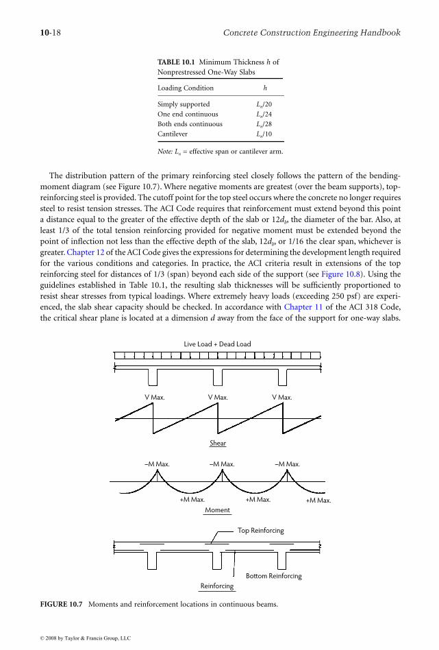
The selection of a beam–slab structural system is most frequently driven by the geometry of a givencolumn bay. Rectangular bays, with an aspect ratio exceeding 2:1, will function to distribute nearly 100%of the shear and moments in the short direction. Configuring beams in the long-span direction only,with slabs spanning one way, perpendicular to the beams, creates a structural system that maximizes thebenefits of each element. In addition, the continuity created by casting the slab system integrally acrosseach beam support allows the framing system to redistribute load between the positive and negativemoment zones so as to provide redundancy at the ultimate load state. Finally, deflections are minimizeddue to the continuity of the system. Under standard loading conditions (see Section 10.2), slabs can bekept thin (see Table 10.1), with reinforcing steel provided primarily in one direction only. Nominaltransverse temperature and shrinkage reinforcement must always be provided to prevent cracking. It isimportant to stress that it is more effective to use smaller diameter bars at closer spacing than largerdiameter bars at larger spacing. The former is essential to controlling cracking development in the slabs.
© 2008 by Taylor & Francis Group, LLC
10-18 Concrete Construction Engineering Handbook
The distribution pattern of the primary reinforcing steel closely follows the pattern of the bending-moment diagram (see Figure 10.7). Where negative moments are greatest (over the beam supports), top-reinforcing steel is provided. The cutoff point for the top steel occurs where the concrete no longer requiressteel to resist tension stresses. The ACI Code requires that reinforcement must extend beyond this pointa distance equal to the greater of the effective depth of the slab or 12db, the diameter of the bar. Also, atleast 1/3 of the total tension reinforcing provided for negative moment must be extended beyond thepoint of inflection not less than the effective depth of the slab, 12db, or 1/16 the clear span, whichever isgreater. Chapter 12 of the ACI Code gives the expressions for determining the development length requiredfor the various conditions and categories. In practice, the ACI criteria result in extensions of the topreinforcing steel for distances of 1/3 (span) beyond each side of the support (see Figure 10.8). Using theguidelines established in Table 10.1, the resulting slab thicknesses will be sufficiently proportioned toresist shear stresses from typical loadings. Where extremely heavy loads (exceeding 250 psf) are experi-enced, the slab shear capacity should be checked. In accordance with Chapter 11 of the ACI 318 Code,the critical shear plane is located at a dimension d away from the face of the support for one-way slabs.
TABLE 10.1 Minimum Thickness h of Nonprestressed One-Way Slabs
Loading Condition h
Simply supported Ln/20
One end continuous Ln/24
Both ends continuous Ln/28
Cantilever Ln/10
Note: Ln = effective span or cantilever arm.
FIGURE 10.7 Moments and reinforcement locations in continuous beams.
Live Load + Dead Load
Moment
–M Max.–M Max. –M Max.
+M Max.+M Max.+M Max.
Shear
V Max.V Max. V Max.
Reinforcing
Top Reinforcing
Bottom Reinforcing
© 2008 by Taylor & Francis Group, LLC

Structural Concrete Systems 10-19
Special detailing requirements are limited in scope for one-way slab design. As long as the load pathto the supporting beam element is maintained, the structure will perform as intended. Thus, openingsparallel to the slab span are easily accommodated by providing internally reinforced headers along theshort edges of the openings. The designer should strive to orient all major openings in a one-way systemsuch that the long dimension is parallel to the span of the slab. No special detailing at columns is required,as the beam element is intended to carry 100% of the load from the slab to the column. One-way slabsystems have the following advantages:
• Long-span capability of the beam elements permits wide column spacings and frame elements forlateral resistance.
• Predictable slab thicknesses, reinforcing requirements, and deflection performance allow thedesigner to concentrate design efforts elsewhere.
• Reinforcing detailing and placement are prioritized in one direction only, reducing complicationat the construction site.
One-way concrete-slab systems are frequently used in parking structures, where the predictable trafficpatterns require long open-column bays in one direction but permit shorter bays in the other direction.
10.6.2 Flat Plates and Flat Slabs
Where the designer is presented with a fairly regular, essentially square column bay, the most econom-ical concrete structural system available is the two-way column-supported slab. As a monolithicmaterial, the placed concrete naturally spans in two directions. By taking advantage of this naturaltendency, the designer can achieve significant economy while maintaining desired deflection control andlateral resistance. Flat plates are distinguished from flat slabs by the treatment at the columns. Bothsystems are entirely beam free; however, flat slabs employ drop caps or column capitals to assist withshear transfer at columns. Flat plates are flat on their underside, and shear transfer is accomplishedby proper proportioning of the concrete plate with the appropriate design and use of shear-momenttransfer reinforcement.
Two-way column-supported slabs derive redundancy from the fact that 100% of the applied loadsmust be carried by the structure in each of the two orthogonal directions. Thus, for a column bay ofwidths Ia and Ib, the structure is proportioned and designed such that 100% of the load can at any timebe carried in either the Ia or the Ib direction. Load transfer in a two-way system is accomplished byeffective widths of slab that serve as shallow beams. For analytical purposes, these effective widths aredivided into column strips and middle strips. By definition, column strips are widths of slab centeredon the column grid line, in both grid directions. The ACI Code specifies that column strips should extend
FIGURE 10.8 One-way slab bar bending and placing detail.
1/3 Larger 1/3 Larger
Top R.E. Bars–span L1 or
Top L.E. Bars–span L2
Adjacent
Span
Adjacent
Span
“T”
Slab Thickness
Bottom
Bars
L2
L.E.L.E. R.E.
L1
6"
Min.
Use
Ho
rizo
nta
l Ext
en
sio
n
Wh
ere
Po
ssib
le
Stan
dar
d 9
0°
or
18
0°
Ho
ck
Temperature
Bars
3/4" CL.Bottom
Bars
Top R.E. Bars–Span L1 or
Top L.E. Bars–Span L2
1/4 L1
1 1/2"
CL.
30Ø
1"
1"
© 2008 by Taylor & Francis Group, LLC

10-20 Concrete Construction Engineering Handbook
0.25L1 or 0.25L2 on each side of the column, whichever is less, where L1 and L2 are the adjacent slabspans. Middle strips occupy the region between the column strips, at the centers of the column bays, inboth directions, as shown in Figure 10.9.
Chapter 13 of the ACI 318 Code addresses the design of two-way slab systems. The code allows thatdesign may be made by any procedure satisfying conditions of equilibrium and geometric compatibility.The code then describes two alternative design approaches: the direct-design method and the equivalent-frame method. The direct-design method is an empirical method developed essentially from the elastictheory of the distribution of moments in continuous slabs. Strict conformance to the limitations must bemaintained or the reliability of the method will be compromised. The slab system must operate within thefollowing constraints if the direct-design method is used:
• There shall be a minimum of three continuous spans in each direction.• Panels shall be rectangular, with a ratio of longer to shorter span, center-to-center of supports,
not greater than 2.• Successive span lengths center-to-center of supports in each direction shall not differ by more
than one third the longer span.• Offset of columns by a maximum of 10% of the span (in the direction of the offset) from either
axis between center lines of successive columns shall be permitted.• All loads shall be due to gravity only and uniformly distributed over the entire panel. Live load
shall not exceed two times the dead load.• For a panel with beams between supports on all sides, the relative stiffness of beams in two
perpendicular directions shall not be less than 0.2 or greater than 5.0.
FIGURE 10.9 Column and middle strips in two-way slabs and plates.
Column
Column Strip
CL
Middle Strip
Column
Co
lum
n S
trip
CL
Mid
dle
Str
ip
l1
0.25l1
© 2008 by Taylor & Francis Group, LLC

Structural Concrete Systems 10-21
Using factors provided in the ACI 318 Code, Chapter 13, the total gravity load acting on the slabsystem is distributed into the column strip and middle strip zones. This method acknowledges that thesummation of the negative and positive moments for any given span must equal the simple beam momentfor a corresponding span. Consequently, the total static moment acting on any panel is denoted Mo, andthe positive and negative moment distribution factors sum to 1.0Mo. For interior spans, the total staticmoment (Mo) is distributed 65% to the negative moment and 35% to the positive moment. End-spanconditions require reference to the tabular information provided in the ACI Code. After the moment-distribution factor is derived, additional factors are employed to proportion the moments between thecolumn strips and the middle strips.
The equivalent-frame method is also essentially based on elastic theory. The slab is divided intoframes comprised of the column grid and the slab on each side, extending to the middle of the panel.Each slab–column frame can be designed separately at each floor level, assuming that the columns arefixed at the floors above and below. Using stiffness coefficients for the various intersecting componentsat the column junction, inclusive of the stiffness of the torsional beam, a moment distribution isperformed. Figure 10.10 illustrates the torsional moment transferred to the slab from the torsionalbeam. The moment of inertia may be calculated using the gross area of concrete. Determining thedistribution of moment through the slabs and columns resolves the flexural phase of the design. Thesecond and perhaps more critical aspect in the design of flat plates or slabs by either method is theshear transfer at the column junction. Because neither the flat-plate system nor the flat-slab systemhas beams that can transfer load into the columns, all of the load carried by the column strips mustbe transferred through the slab thickness. In a flat-slab system, drop caps and column capitals can beused to supplement the shear capacity of the slab concrete alone. The designer must consider twoforms of shear transfer.
As seen in Figure 10.11, a portion of the unbalanced moment is transferred to the column by a verticalbalancing couple in the form of vertical shear acting at the face of the column, while another portion istransferred by a horizontal force couple (flexure) occurring within the slab depth. ACI 318, Chapter 11,indicates that approximately 60% of the unbalanced moment is transferred by flexure, with the balancetransferred by shear. These percentages have to be calculated for each case. The designer must rememberthat the vertical reaction due to gravity loads in the slab must be added to the unbalanced moment forcesto gain a complete picture of the slab–column interface.
FIGURE 10.10 Torsional beam element in two-way action.
l1 l2
C2
CL
Panel
CL
Column
CL
CL
Panel
A
B
Cmt
mt
Mt
Edge Beam
© 2008 by Taylor & Francis Group, LLC

10-22 Concrete Construction Engineering Handbook
For columns that are essentially square in cross-section, such shear failure typically governs theproportioning of the plate or column cap. The shear-failure plane occurs as a 45° crack that forms aroundthe full perimeter of the column. The failure plane is angled upward from the bottom of the column.The critical shear zone for analysis is considered to be a distance d/2 from the face of the column, whered is the effective depth of concrete above the reinforcing.
Where the applied shear forces greatly exceed the concrete-slab shear strength, the designer has twoprimary options. One is to provide additional concrete in a region slightly wider than the critical shearzone; this is accomplished by adding a flat drop cap consisting of several additional inches of concrete.Alternatively, a column capital, shaped like an inverted cone, can be provided to widen the critical shearzone and to thicken the concrete in the zone, thereby increasing the concrete shear capacity. Chapter 35 ofthis Handbook lists the maximum allowable shear capacity (Vc) that can be used in the design for two-wayaction to determine the thickness of the plate or slab as governed by shear. The other alternative is the useof special steel reinforcing assemblies. Commonly referred to as shear heads, these assemblies can consistof steel beams or channels welded in a cross shape, placed on top of the column, and poured monolithicallywith the slab. Other shear-head assemblies consist of flat steel bars with welded-head shear studs. Theseassemblies are placed so they overlap the column and extend outward, thus increasing the critical shear zone.
Where significant shear-head reinforcing is required, the slab is proportioned too thin for the appliedloads or the tributary areas. Shear failure is a sudden failure mode. The designer must exhibit extremecaution in analyzing shear transfer. Although not in favor for many architectural designs due to infringe-ment of the ceiling plenum space, drop caps provide the designer with a simple but effective means ofincreasing slab capacities without resorting to complicated reinforcing schemes that are ultimately onlyas reliable as the installation method. The designer is encouraged to analyze the perimetric punchingshear transfer as early in the design process as possible.
A final means of increasing the slab shear capacity, if the other two alternatives are not economicallyjustifiable, is increasing the size of the columns. In practice, this method is only effective when thedifferential between the applied shear force and the slab capacity is within 20%. In this case, a 4-in. increasein the column dimensions will increase the slab shear capacity sufficiently to support the shear transfer.
As noted earlier, perimetric shear is typically the governing shear condition for design purposes;however, where rectangular columns with an aspect ratio in excess of 2:1 are provided, one-way beamshear can govern the slab thickness. Where applied shear forces exceed the concrete capacity, drop capscan be employed to increase the critical shear zone and the thickness of the concrete. Column capitalsare not used for rectangular columns. The designer may find more success in increasing the longdimension of the column, if this option is available.
FIGURE 10.11 Shear-moment transfer mechanism.
rcM
V1V2
© 2008 by Taylor & Francis Group, LLC

Structural Concrete Systems 10-23
10.6.2.1 Post-Tensioned Two-Way Plates
Prestressed, post-tensioned, two-way floors are frequently used today, particularly in apartment build-ings. The primary advantages of post-tensioning are the ability to use thinner slabs, the crack controlderived from the presence of a significant precompression force in the concrete, greater shear capacityas a result of the precompression force, and greater deflection control as a function of reverse cambering.The designer is cautioned that the advantages realized from post-tensioning in the slab elements canquickly be lost in the column elements. The extremely high compression forces generated by the ten-sioning strands cause large unbalanced moments in exterior columns. To adequately reinforce thecolumns to resist these forces, much of the available room for shear reinforcing and negative flexuralsteel is occupied. The designer must carefully detail these conditions to ensure that no conflicts existamong the different types of required reinforcement that could jeopardize the design once it is underconstruction. The final aspect of two-way column-supported slab design considered here is the transferof lateral moments between the slab–diaphragm system and the columns. Under uniform gravity loading,flexural stresses are essentially balanced at interior columns, and shear transfer is accomplished viaindependent analysis. Where unbalanced moments are to be transferred into the columns, the analysisof shear and flexure becomes combined. Analysis of this moment transfer requires calculation of thepolar moment of inertia for the column element. Then, by applying the standard stress analysis theoryof shear stress and bending stress, the proportion of the slab or drop cap at the column head can bechecked. The designer is cautioned that the analysis of punching shear as a function of unbalancedmoment transfer is of utmost importance and should be addressed as early in the design process aspossible to allow for changes in the structural approach, if necessary. Because slabs tend to be thinnerin post-tensioned systems, the analysis of punching shear and unbalanced moment transfer at thecolumns takes on even greater significance.
10.7 Liquid-Containing Structures
10.7.1 Introduction
Concrete structures for liquid containment consist mainly of water-treatment plants, wastewater-treat-ment facilities, tanks, and reservoirs. The concrete used for these facilities should be watertight and shouldbe protected against contamination from groundwater. In addition, exposed concrete structures requireprotection against freeze–thaw damage and environmental effects. In containment concrete, low waterpermeability and low shrinkage are essential to prevent damage and cracking of concrete. Althoughproper design, such as specifying proper control joints and reinforcing steel, is important, the mosteffective way of controlling shrinkage and minimizing water permeability is by designing good-qualityconcrete mixes. In addition, proper concrete quality, concrete batching, delivery to the site, and placingare essential factors for good quality containment concrete.
The compressive strength of concrete used for containment structures should be a minimum of 4000psi at 28 days of age. The air content should be 6 ± 1%. The amount of mixing water should be enoughto produce a slump of 2 to 3 in. The minimum cement content for a 4000-psi concrete should be 560lb/yd3. Containment concrete should have a maximum water/cement ratio of 0.45 lb/lb.
The use of a water-reducing admixture generally helps reduce the amount of mixing water used. Theuse of high-range water reducers may also be used to reduce the amount of mixing water and increasethe slump, easing the placement. Slump after the addition of superplasticizers should not exceed 7 in.In warm weather, a high-range water reducer and retarder may be used to prevent quick setting of thecement. For more information on admixture types and their functions, ASTM C 494 as well as reputableadmixture manufacturers may be consulted.
To further reduce permeability and increase the density and durability of concrete, the addition ofmicrosilica to the concrete mix may be considered. In general, the addition of 5% microsilica by weightof Portland cement reduces the permeability of concrete considerably. Microsilica-containing concreteis widely used for parking garage floors to reduce chloride infiltration into the slabs.
© 2008 by Taylor & Francis Group, LLC

10-24 Concrete Construction Engineering Handbook
The size and amount of coarse aggregate used in concrete are also governing factors in controlling theshrinkage and cracking of concrete. The size of aggregate should not exceed 1-1/2 in. (ASTM C33, size#57). The amount of coarse aggregate should be between 1750 and 1850 lb/yd3. The higher the amountof coarse aggregate, the lower the amount of sand, which is a factor in controlling shrinkage. All otherconcreting practices such as placement techniques, finishing procedures, and curing should be done asper the ACI specifications. The joint type and spacing as well as the reinforcing percentage and the otherdesign details of the project should be designed by the structural engineer.
The most important aspect of concrete tanks is that they must be leak free. This requires that carefulconsideration must be given to the analysis, detailing, and construction of tanks. The requirement thatthe tanks be free of leaks leads to the rather obvious conclusion that the stresses in the tank must bemust be below the modulus of rupture. Because reinforcing becomes effective at strains near those thatcause cracking in concrete, reinforcing is present in the tanks to resist the tensile stresses if the concreteruptures, thus averting a catastrophic failure. The thickness of the walls is therefore selected to keep shearand flexural stresses below the cracking point. The ideal configuration for tanks is the circular shape.Resisting loads with tensile members is more efficient than doing so with flexural members. Most of theloads generated by the contents of a circular tank are very efficiently resisted by circumferential tensileforces. When space or process constraints must be considered, rectangular tanks may be the proper choice.
10.7.2 Circular Tanks
The analysis and design procedures for circular liquid-containing tanks are not complicated. They followthe elastic theory of shells (Billington, 1982; Nawy, 2003). The method basically consists of a membraneanalysis of the tank with the introduction of shears and moments to account for boundary conditionsthat are noncompliant with the membrane theory. The Portland Cement Association (PCA) publicationCircular Concrete Tanks Without Prestressing (PCA, 1992) provides procedures and examples for the designof circular tanks. Much of the information and formulas contained herein are extracted from the PCApamphlet. There are also computer programs that can analyze these tanks. From a practical standpoint,it should be noted that the base slabs for most tanks are relatively thick for several reasons and thenominal amounts of steel to control volumetric changes of the concrete result in capacities greater thanthose required by the analysis.
The basic approach to design of a circular tank is to select a wall thickness that is strong enough thatthe stresses in the wall will always be less than the modulus of rupture of the concrete. Circumferentialreinforcing is provided to carry all of the ring tension should the concrete crack. Vertical reinforcing isselected to resist the flexural stresses caused by the support conditions. It is interesting to note that usingreduced allowable stresses in the reinforcing steel causes higher stresses in the concrete. The area ofreinforcing steel required to resist the ring tension (T) is:
(10.5)
where As is the area of steel required, and fs is the design stress for the reinforcing steel. The stress in theconcrete can be expressed as:
(10.6)
where fc is the stress in the concrete, C is the thermal coefficient of expansion, As is the cross-sectionalarea of the steel, Ac is the cross-sectional area of the concrete, n = Es/Ec, and Ec and Es are the moduli ofelasticity of concrete and steel, respectively. Inserting varying design stresses for the reinforcing confirmsthat as the steel design stresses decrease the stresses in the concrete increase. Of interest is the revelationthat, as the design stress of reinforcing approaches infinity, As approaches zero and the stress in theconcrete approaches T/Ac. In other words, the effects of thermal stresses disappear.
AT
fs
s
=
fCE A T
A nAc
s s
c s
= ++
( )
( )
© 2008 by Taylor & Francis Group, LLC
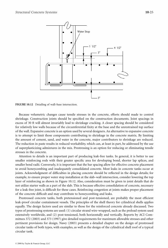
Structural Concrete Systems 10-25
Because volumetric changes cause tensile stresses in the concrete, efforts should made to controlshrinkage. Construction joints should be specified on the construction documents. Joint spacings inexcess of 30 ft will almost invariably lead to shrinkage cracking. A closer spacing should be consideredfor relatively low walls because of the circumferential fixity at the base and the unrestrained top surfaceof the wall. Expansive concrete is an option used by several designers. An alternative to expansive concreteis to attempt to limit those components contributing to shrinkage in the concrete matrix. By limitingthe amount of cement, sand, and water in the concrete, major contributors to shrinkage are reduced.The reduction in paste results in reduced workability, which can, at least in part, be addressed by the useof superplasticizing admixtures in the mix. Prestressing is an option for reducing or eliminating tensilestresses in the concrete.
Attention to details is an important part of producing leak-free tanks. In general, it is better to usesmaller reinforcing rods with their greater specific area for developing bond, shorter lap splices, andsmaller bend radii. Conversely, it is important that the bar spacing allow for effective concrete placementto avoid honeycombing and inadequately consolidated concrete. Most leaks in concrete tanks occur atjoints. Acknowledgment of difficulties in placing concrete should be reflected in the design details; forexample, to ensure proper water stop installation at the slab–wall intersection, consider lowering the toplayer of reinforcing as shown in Figure 10.12. Also, consideration must be given to joint details that donot utilize starter walls as a part of the slab. This is because effective consolidation of concrete, necessaryfor a leak-free joint, is difficult for these cases. Reinforcing congestion at joints makes proper placementof the concrete difficult and may contribute to honeycombing and leaks.
Prestressed concrete tanks, both pretensioned and post-tensioned, are probably the most efficientleak-proof circular containment vessels. The principles of the shell theory for cylindrical shells appliesequally. The design factors used are similar to those for the reinforced concrete already discussed. Twotypes of prestressing systems are used: (1) circular strand wire-wrapped, such as the preload system usedextensively worldwide, and (2) post-tensioned, both horizontally and vertically. Reports by ACI Com-mittees 372 (2003) and 373 (1997) give detailed requirements for maximum allowable stresses and otherpertinent provisions for design. Nawy (2003) presents a detailed chapter on the design of prestressedcircular tanks of both types, with examples, as well as the design of the cylindrical shell roof of a typicalcircular tank.
FIGURE 10.12 Detailing of wall–base intersection.
1 1/2"4 1/2"
3''
3"
Water Stop
© 2008 by Taylor & Francis Group, LLC

10-26 Concrete Construction Engineering Handbook
10.7.3 Rectangular TanksPerformance criteria for rectangular reinforced concrete tanks are usually similar to those of circulartanks—namely, no leakage. The wall thickness of relatively shallow tanks is dictated by the need to keepflexural stresses below the modulus of rupture. The wall thicknesses of deep tanks, such as those associatedwith pump stations, are often dictated by shear stresses; flexural stresses are usually less than the modulusof rupture cracking stresses. The Portland Cement Association’s Rectangular Concrete Tanks (PCA, 1998)provides guidelines and design procedures. Extensive additional information is available in the literature(see, for example, Timoshenko and Woinowsky-Krieger, 1959; Young, 1989). The corners of rectangulartanks tend to be subjected to large stresses; hence, considerable attention should be devoted to detailingand joint placement to limit cracking to an acceptable minimum. Construction joint locations must beincorporated into the design documents to limit the effects of volume changes. As the horizontal dimen-sions of the tanks increase, the effects of the corners diminish, and the wall behaves more like a cantileveredretaining wall. Introduction of counterforts reintroduces two-dimensional behavior and should be con-sidered in long walls. This technique can also be utilized for large-diameter circular reinforced concretetanks in which the circumferential stresses become exceedingly large. Buried rectangular tanks present aspecial problem at wall corners. Slabs at the corners of rectangular tanks tend to curl upward; thus, thecorners must be properly attached to the walls. Because diagonal cracks occur at the corners, additionaldiagonal reinforcing steel is usually provided.
10.8 Mass Concrete
10.8.1 IntroductionLarge structures such as dams, bridge foundations, mat foundations, nuclear plants, and large-span deepbeams require the placement of large quantities of concrete that are required to act in a monolithicmanner. The successful placement of mass concrete requires careful planning, mixture design, placement,and consolidation. Quality mass concrete, like other concrete, begins with the proper mixture for thejob. Volume changes within the concrete can cause internal cracking, with its attendant reduction instrength and degree of watertightness. To keep shrinkage to a minimum, factors that are major contrib-utors to shrinkage must be controlled. Successful placement of mass concrete requires the prevention ofearly setting of the cement and shrinkage of the concrete. During the placement of concrete, the tem-perature increases due to the hydration of the cement; therefore, minimizing the increase of heat ofhydration is essential to prevent shrinkage and cracking of the concrete. The publication Control ofCracking in Concrete Structures (ACI Committee 224, 2001) deals with the preventive measures necessaryto control internal temperature in mass concrete. Concrete used for various large structures has to haveexcellent control of early setting to prevent shrinkage, cracking, and problems associated with placementand workability of concrete. Among the factors to be considered for mass concrete are the following:
• Engineering design details of mass concrete (this phase of the work requires considerable knowl-edge and experience of structural engineering)
• Selection of materials and proportioning of concrete mixes• Control of concrete quality during batching and placement
10.8.2 Materials for Mass ConcreteThe following materials are appropriate for mass concrete:
• Portland cement with low heat of hydration. It is common to use Type II or Type IV Portland cement(ASTM C 150). The minimum amount of Portland cement should be used to achieve the designstrength.
• Pozzolans (ASTM C 311 and ASTM C 618). Addition of a pozzolan such as fly ash in the rangeof 20 to 25% by weight of cement will assist in reducing the heat of hydration and improvingworkability and long-term strength gain.
© 2008 by Taylor & Francis Group, LLC

Structural Concrete Systems 10-27
• Aggregates (ASTM C33). Both fine and coarse aggregates should meet ASTM C 33 requirements.For dams, the coarse aggregate should preferably be size No. 1. In case of structural mass concretefor beams, coarse aggregate should have a nominal size of 1 to 1-1/2 in. The amount of coarseaggregate should be high, approximately 1900 lb/yd3 of concrete. Especially in concrete dams, theratio of fine aggregate to total aggregate by absolute volume should be low—approximately 25%.
• Mixing water. The amount of mixing water to be used should be low to provide a slump of 2 to 3 in.• Admixtures. Admixtures should be used to entrain air and reduce the water/cement ratio. The
water reducer should preferably be a Type D water-reducing and retarding admixture, as specifiedin ASTM C 494.
• High-range water-reducing (HRWR) admixtures. Mass concrete to be pumped should be treatedwith either an HRWR admixture (Type F) or an HRWR and retarding admixture (Type G) asspecified in ASTM C 494. The slump before the addition of the superplasticizer should be 2 to 3in.; after the addition of superplasticizer, the slump should be 5 to 7 in.
• Coolants. The temperature of mass concrete for dams should be controlled to be between 40 and50°F, especially in hot weather conditions. Finely chipped ice may be added to concrete to controlthe temperature. Other methods of cooling the aggregates, such as keeping them damp and undershaded conditions, will reduce the temperature. When steel forms are used, they should be sprayedwith cold water if necessary. Curing the concrete with cold water also will help in controlling thetemperature of cast concrete. The maximum temperature for mass structural concrete, such as beams,should be 70°F. In this case also, the use of chipped ice may be considered to lower the concretetemperature.
10.8.3 Concrete Mixture Design
Concrete mixtures used for mass concrete should be proportioned in a qualified laboratory in accordancewith ACI Committee 211.1-91 (Standard Practice for Selecting Proportions for Normal, Heavyweight andMass Concrete; reapproved 2002). The materials used in concrete mix designs should be the same materialsintended for use in the project. The compressive strength of concrete used for dams generally is low,3000 psi to 3500 psi. The full design compressive strength is achieved 6 to 12 months after placement.In the case of mass structural concrete, the design compressive strengths are generally between 4000 and6000 psi. The design strength is based on 28-day age.
10.8.4 Quality Control
Thorough quality control and quality assurance are essential for the proper execution of a mass concreteproject. The selection and quality of ingredients to be used, batching, and placing of the concreteshould be observed, and the necessary tests should be performed as per the applicable ACI and ASTMspecifications. Equipment that allows rapid placement of large concrete quantities should be used toreduce the possibility of cold joints. The typical low-water, low-slump concrete used for mass con-creting must be properly consolidated to eliminate cold joints and honeycombing. Segregation ofaggregates must be avoided. Large-volume delivery systems are less susceptible to segregation thansmaller volume systems. With minimum handling, there is less potential for segregation. Large-volumebuckets with their wide discharge openings are effective means of delivering large quantities withminimum segregation. When it has been placed, the concrete must be properly vibrated to knitsuccessive layers together in a joint-free matrix. Transportation of concrete using vibrators should notbe done because of the potential for segregation. Preplacement planning must include the involvementof the concrete supplier to resolve potential problems such as truck breakdowns or the opposite—abackup of trucks leading to excessive mix time. Effective communication is an absolute must. Properequipment maintenance greatly reduces the potential for breakdown. If a pump-delivery system isutilized, consider having a spare unit on-site to ensure an uninterrupted delivery to the point ofplacement.
© 2008 by Taylor & Francis Group, LLC

10-28 Concrete Construction Engineering Handbook
10.9 On-Site Precasting and Tilt-Up Construction
On-site precasting is used in lift-slab, tilt-up, and miscellaneous general construction. Lift-slab on-siteprecasting consists of casting the floor and roof slabs on top of one another so they can be lifted intoplace once the columns and jacking equipment are in place. Section 10.10 discusses the lift-slab systemin more detail, so specifics of the system are not discussed here. Site-casting of the slabs provideseconomies resulting from:
• Reduced formwork costs, as only edge forms are required and these are reused several times• Reduced placing costs, as all of the concrete placement is at ground level• Reduced curing and protection costs due to the limited surface area exposed to the elements• Reduced reinforcing costs due to the considerable repetition from floor to floor and because the
materials do not have to be hoisted to elevated floors• Uniformly flat soffits of the slabs, thus simplifying design and installation of mechanical and
electrical systems• Favorable fire-resistance ratings that may be obtained without the application of fireproofing to
the underside of the slabs
Several of these advantages can also be realized by site-casting specific structural members. In thenortheastern portion of the United States, it is not unusual to site-cast concrete columns to be used withstructural steel roof systems. The concrete columns provide favorable fire protection ratings while alsoproviding high-capacity concrete members at a price that compares very favorably with structural steelcolumns. The site-cast columns can be made as durable as steel columns with respect to impact damagefrom material-handling equipment. The majority of site-cast concrete is used in tilt-up construction. Inaddition to many of the potential cost savings listed above, tilt-up construction can replace exteriorstructural steel with concrete bearing walls that can be architecturally treated at a relatively low cost.Figure 10.13 shows the various components and their arrangement along a bearing wall of a tilt-upbuilding. Basically, the system consists of the following steps:
• Prepare the site and cast the footings.• Cast the slab on grade, omitting a strip several feet wide around the perimeter of the building and
erosion-control measures such as draping plastic sheeting over the exposed soil at the perimeterof the building between the exterior footings and the edge of the slab on grade.
• Place edge forms for the wall panels directly on top of the slab on grade.• Patch any blemishes on the surface of the slab on grade, and temporarily patch all joints occurring
within the area of the wall panels as these will read through onto the wall panels.• Apply a high-quality bond breaker to the slab on the grade surface.• Apply any architectural finishes that will be exposed on the surface cast against the slab on grade.• Place reinforcing and tilt-up hardware, such as lift and bracing inserts, and place the concrete,
using care to avoid shifting reinforcing, inserts, or architectural finishes.• Apply curing compound or moist cure wall panels.• Install bracing inserts in the slab on grade if they have not been previously placed.• Place leveling pads on footings, and mark for transverse and longitudinal alignment.• Tilt up wall panels and lift into position using a suitably sized rubber-tired moving crane.• Brace wall panels to slab on grade using a system of pipe braces and dimensional lumber attached
to the wall and slab at the appropriate inserts.• Stabilize the base of the wall using concrete infill at the oversized shear key in the footing.• Erect the structural steel; when the entire structure is plumbed and square, weld structure to tilt-
up wall panels.• Backfill around the exterior and interior of the perimeter footings.• Extend the slab connection reinforcing from the wall panels and place the perimeter strip between
the wall and edge of slab on grade.
© 2008 by Taylor & Francis Group, LLC

Structural Concrete Systems 10-29
Although greater economies can be realized by using the system for bearing-wall construction, thesystem also deserves consideration when nonbearing walls are contemplated. The system usually becomeseconomical when the floor area is 40,000 ft2 or more. Obviously, this threshold area will vary from regionto region. The important requirement is to have adequate room to precast the panels on the floor slab.Local labor rates and work rules will also affect the viability of the system. In northern regions, it wouldnot be prudent to begin a tilt-up project at the onset of winter or other anticipated extended periods ofinclement weather. It is especially important not to leave a slab on grade that is exposed to freezingweather unprotected because of the possibility of the slab heaving. Irregularities in the slab such as thisare difficult to remove and will read through to the wall panels. Typically the wall panels are cast so thatwhen lifted the exterior panel face is cast against the slab or facing upward. Tilt-up panels are also caston concrete site paving in addition to the interior slab on grade. Another option is to use temporary sitecasting beds or to stack cast the panels.
The exterior face-down casting position provides an opportunity to economically treat the exteriorface of the panel if desired. Because the contact surface of the floor slab will in all probability containblemishes, treatment of the wall panels may be more effective than the elimination of floor blemishesthat might very well be acceptable for the intended floor use. Typical finishes for the panels includegraphics formed into the surface, accents, aggregate finishes, or combinations thereof. Accent strips areconstructed using inexpensive dimensional lumber. The exposed aggregates are placed on a layer oftreated sand that is bounded by the accent strips. Prior to placing the surface aggregate the sand receivestwo applications of bond breaker to prevent the concrete from adhering to the sand or the aggregate.After the sand has been sprayed, the aggregates are carefully spread over the areas to receive the finish.
FIGURE 10.13 Typical panel bracing.
ThreadedCoil Rods2' – 0 o/c
Top ofFl. Slab
WallPanel
Coil LoopInsert
Alternate Detail
Coil Loop insertWith ¾"Ø Coil Bolt
Provide KneeBrace Mid-Point
Adjustable DiagonalPipe Brace
Top ofFl. SlabWall Tie
Reinforcing
Plastic Sheetingto Reduce Erosion
CompactedFill
Insert with Coil Bolt orExpansion Bolt.
Place Before Wall Panels Are Cast.
Footing
Wall TieReinforcing
Tilt–UpConcrete Panel
© 2008 by Taylor & Francis Group, LLC

10-30 Concrete Construction Engineering Handbook
Care must be exercised during the placing operations to avoid displacement of the aggregates. Stainless-steel reinforcing accessories must also be utilized, or rust staining of the surface will occur. During thedesign, reducing thickness to accommodate the surface treatment of the panels must be considered.
Footings supporting the wall panels may either be continuous or discrete. If continuous footings arenot utilized, additional horizontal reinforcement near the bottom of the panels must be provided toensure adequate flexural capacity to enable the panel to span from footing to footing. In many cases, useof continuous footings is an option that results in ease of construction and reduction of potential fordifferential settlement.
Panel thicknesses are determined by the economics of reduced concrete and panel lift weight vs.additional reinforcing. Panel thickness is also related to the number and arrangement of lift insertsnecessary to ensure that the flexural stresses are kept below the cracking level. Allowance for an increasein stress resulting from partial adhesion of the panel to the slab on grade, if a sand or aggregate layer isnot used, should also be incorporated into the design. The panels will almost certainly be considered tobe slender compression elements, requiring that the effects of panel deflection (P-delta) under lateralloads be considered in the analysis, in addition to global effects as a result of the diaphragm deflection.If the structural framing for the roof utilizes steel joists, the connection of the joist bottom chord to thepanels should be avoided as the deflection of the joists will introduce a potentially large moment intothe panels through the fixity of the top and bottom chords. It is more economical to consider theadditional unsupported height in the design of the panel. If possible, seat the joists at or near the mid-depth of the panels to reduce the eccentricity of the loads supported by the panels.
Lateral loads can be resisted through horizontal diaphragm action in the roof structure. The lateralloads can effectively be transferred from the roof deck to the wall panels as shown in Figure 10.14. Theangle is also a cost-effective replacement for a joist placed adjacent to the panel and simplifies roofingdetails through its zero displacement. Panels at corners should always be connected across the cornerjoint to ensure alignment. Panel joint connections elsewhere are a function of the need to engage morethan one or more panels for overturning shear wall action. In addition, in high seismic areas, thecontinuous diaphragm chord is typically accomplished by connecting continuous rebar along the top ofthe panels across the joints.
10.10 Lift-Slab Construction
10.10.1 Introduction
The lift-slab method of construction was first introduced in the 1950s by Phillip N. Youtz, who laterjoined Thomas B. Slick to refine the design concept and construction techniques of his system. Fromthis research, the original concept of lift-slab construction was introduced. The structural componentsof lift-slab buildings are no different from conventionally constructed buildings. The difference is howthe building is erected. The procedure is to cast the concrete floor slabs, one on top of the other, on theslab on grade and lift them to their final elevation with hydraulic jacks (Russillo, 1988). Lift-slab concrete
FIGURE 10.14 Alternative detail of transfer of lateral loads.
Roof DeckSupport Angle
Concrete
Tilt-Up Panel
Coil Loop
Insert
Roof Deck
© 2008 by Taylor & Francis Group, LLC

Structural Concrete Systems 10-31
construction is seldom used any more, so the following discussion is provided more as a historicalreference. The first step is to prepare the site for construction and install the foundation system for thebuilding, using normal construction techniques. The first level of columns is then erected on the foun-dation with the steel lifting collars in place. The columns are usually two stories high for economy. Whenall of the columns are in place, the concrete slab on grade is placed, allowed to set, and coated with aseparating material. The first steel shear collar is then slid down the column and is aligned on the slabon grade. The slab reinforcing is installed, along with embedded electrical conduit and plumbing linesdirectly on the slab surface. The edge of the slab is formed, and finally the concrete is placed. The aboveprocedure is repeated for each of the supported floors plus the roof. When the roof slab is completed, itis loaded with the upper column sections and the slab-lifting equipment. The lifting jacks are placedatop each of the columns and are connected to the roof-lifting collar by threaded rods. The roof slab isthen lifted to the top of the column section and temporarily secured. With the roof slab in this position,the tops of the columns are braced and the column capacity is increased for the successive lifts. The upperlevel slabs are then lifted to the underside of the roof and are temporarily secured. The lower level slabsare lifted and are permanently attached to the column sections at their designated elevations. The liftingjacks are removed and the next column sections are erected. The jacks are then placed on top of the nextcolumn section, and the lifting sequence is repeated until all the floor and roof slabs are in their finalposition. When all of the slabs are secured to the columns, the exterior facade can be constructed, andthe floors are ready to be fitted out.
10.10.2 Foundations
The process of lifting the precast concrete slabs does not impose any loads on the foundation system thatare different from the design service loads. No special foundation requirements are necessary for thistype of construction. The foundation type is selected and proportioned based on the geotechnicalcharacteristics of the project site and the dead loads and service live loads anticipated for the occupancyof the building. The concrete slab on grade is to be placed and finished based on the requirements of itsend use. Note that the finish of the slab will be reflected on the ceiling above. Any depressions in the slabon grade for floor finishes can be filled with lean concrete to prevent them from being reflected on theceilings above.
10.10.3 Columns
The columns for lift-slab buildings are usually steel wide-flange shapes, but precast and cast-in-placeconcrete columns have also been used. Our discussion here is limited to steel wide-flange shapes, althoughconcrete columns are similarly erected. The length of the column sections is usually two stories high andis limited by the design column section and the length of the lifting rods supplied by the contractor. Nolimiting column-spacing requirements are imposed by the lift-slab process. It is controlled by architecturallayout, span of the slabs, and the loads supported by the slab. The lift-slab contractor may, however, limitthe total area to be lifted at a time, thus dividing the slab into sections. This is determined by the numberof jacks and support equipment available to the contractor. The boundary between two adjacent slabs isknown as a pour strip. After the slabs are lifted into place, these areas are formed and concrete is placedto complete the floor system.
10.10.4 Supported Slabs
The concrete slabs used at the inception were conventionally reinforced two-way flat slabs. These slabsworked well, were easy to construct, and were sized to eliminate drop panels. This limits formwork toblockouts for the mechanical chases and perimeter-slab edge. The major drawbacks with conventionaltwo-way slabs are that they are thick and heavy and their spans are relatively short. Today, most slabsare two-way flat plates that are post-tensioned. Post-tensioned slabs are thinner for the same loadingconditions or have greater capacity for the same span and slab thickness. The slabs are generally the
© 2008 by Taylor & Francis Group, LLC

10-32 Concrete Construction Engineering Handbook
same, whether the building is lift-slab or conventionally constructed. The advantage is obtained by castingall the slabs at grade level, one on top of the other. It is not necessary for large cranes to hoist materialto the elevated floors, a man lift is not required, the time required to move material is reduced, and thefall hazard for the workmen is nearly eliminated.
10.10.5 Lifting CollarsLifting collars, threaded onto the columns prior to erection, are centered on each column and cast intoeach of the supported slabs. The original steel castings were found to be expensive and had limited liftcapacity. Today, lift collars are exclusively steel sections that are welded with full-penetration welds. Thepurpose of the lift collar is threefold: It connects the slab to the lifting jack via a threaded rod, attachesthe slabs to the columns for load transfer, and acts as shear reinforcement in the slabs (shear heads) toeliminate drop panels in the thinner post-tensioned slabs.
10.10.6 Lifting JacksThe lifting jacks used to raise the slabs are mounted to the top of each of the columns and are attachedto the slab by two threaded rods. The jacks are hydraulic and are driven in such a manner that they liftin unison at a rate of 4 to 10 feet per hour. This is to eliminate damage to the slabs as they are being lifted.
10.10.7 Critical Component DesignThe design of the structural components of a lift-slab building is, for the most part, the same as for aconventionally constructed building. The differences occur in the critical components such as the liftingcollar, the slab at the column connection, and the columns, which need to be checked for all conditionsand end restraints during construction.
10.10.7.1 Columns
The columns of a building utilizing the lift-slab method of construction serve a dual purpose in thatthey support the building in its final position, braced at each floor by the slab, and they are used tosupport the lifting jacks during positioning of the slabs. The columns require analysis for all the loadcases proscribed by local building codes as well as for construction loads. During jacking of the roof slab,the columns are freestanding, with base fixity achieved by the base plate detail and encasement of thecolumns by the slab on grade. The stage during which the roof slab is lifted up along the freestandingcolumns is the most critical condition. The column sections must be sized for this condition as well asfor conditions during successive lifts. The first load condition is best checked using Euler’s column formulafor columns fixed at the base and free at the top:
where:
P(all) = allowable load (kips).E = modules of elasticity (kips/in.2).I = moment of inertia (in.4).L = column height (in.).F.S. = factor of safety.
When the roof slab is at the top of the column section and has been secured (temporarily or perma-nently), the slab connects all of the columns together and fixes the top of the column section. The columncondition now becomes fixed at the bottom and fixed against rotation at the top but is allowed to translatelaterally. This condition reacts the same way as columns that are pinned at both ends and is analyzedusing the following column expression:
PEI
L(all)
F.S.= π2
24 ( )
© 2008 by Taylor & Francis Group, LLC

Structural Concrete Systems 10-33
The capacity of the columns at this stage quadruples. This extra capacity in the columns may allow anumber of slabs to be lifted simultaneously.
10.10.7.2 Lift Collar
Lift collars (see Figure 10.15) must be designed to perform adequately for multiple purposes. The collaris sized to transfer the construction loads imposed on the slabs to the lifting jacks and all of the serviceloads to the column. Finally, the collar must be sized to reinforce the slab to keep the diagonal tensionstresses in the slab below the allowable stress dictated by the building code. The design of the collar alsodepends on the forces to be transferred from the slab to the column. Depending on the designersassumptions, the forces could be shear only, shear with partial-moment transfer, or shear with full-moment transfer. The design of the lift collar is the responsibility of the lift-slab contractor. The designengineer should note the type of collar desired and anticipated design forces on the design documents.
10.10.8 Applications
The lift-slab method of construction is best suited for buildings whose column layout is ideal for two-waypost-tensioned concrete slabs. Although higher structures have been lifted, up to 20-story buildings arethe best candidates. The exterior facade does not affect the decision as to whether this system should orshould not be used. Constricted construction sites warrant investigation of the lift-slab method becauselarge track-mounted tower cranes are not required. When construction of the superstructure is scheduledto occur during cold seasons, this approach becomes economical in that when the foundation is completedand the columns have been erected a shelter can be constructed and heated to provide a protected work area.
10.11 Slip-Form Construction
10.11.1 Introduction
Vertical slip-form construction is a process of placing concrete continuously with a single form that isconstructed on the ground and raised as the concrete is cast. Casting is done at a rate that prevents theformation of a cold joint in previously placed concrete. The result is a continuous placing sequence
FIGURE 10.15 Lift collar in lift-slab construction.
PEI
L( )
( )all
F.S.= π2
2
© 2008 by Taylor & Francis Group, LLC

10-34 Concrete Construction Engineering Handbook
resulting in a monolithically erected wall with no visible joints. This construction process utilizes liftingjacks located on the ground or on the working platform that elevates the form and the workers’ scaffoldingattached with smooth rods or pipes. These rods or pipes are embedded in the hardened concrete. Theconstruction technique is similar to an extrusion process.
The die (slip form) moves upward as it extrudes the concrete wall. The rate of the extrusion processis controlled by the setting time of the concrete and the crew’s ability to prepare the wall for the pour.The average time of lift for any project is 6 to 8 in./hr, placing approximately 4- to 10-in. layers of concreteper lift; however, the time varies anywhere from 2 to 4 in./hr for the lower levels of a nuclear reactorcontainment structure to 20 to 50 in./hr for an underground shaft lining. The project foreman looks forzero slump from the 4- to 10-in. layer below the layer being placed.
It is important to note that, when this construction procedure is utilized, the concrete wall beingslipped through supports only its own weight. The jacking rods located in the wall support the weightof the slip-form structure. The concrete keeps the jacking rods from buckling. In some cases, the jackingrods become part of the permanent structure. The other alternative is to have the jacking rods slip througha thin pipe sleeve as the form slips upward. Engineers designing these walls should not rely on the steelrods for reinforcement due to lack of bond between the bars and the concrete.
Slip-form construction, even though in a state of continuous motion, can be interrupted by weekendsand evenings simply by extruding the form away from the poured wall as it sets. The form should neverbe allowed to adhere to the concrete. Slip-form construction is used for various applications, such asbridge piers, building cores, apartment-house shear walls, chimneys, communication towers, coolingtowers, and silos, among many other applications. In many cases, the procedure can be used to erect astructure in half the time of conventionally formed work. In addition, the working platforms rise withthe form and reduce the labor costs of dismantling and re-erecting scaffolds at each floor. Close inspectionof the concrete must be performed at all times to ensure elimination of blowout (concrete plastic state)or bonding of concrete to the slip form during the construction process.
10.11.2 Materials and Methods
The major components of a slip-form assembly consist of lifting jacks and rods, yokes, wales, sheathing,a working platform, and suspended scaffolding (see Figure 10.16). All components, with the exceptionof the lifting jacks and concrete, climb integrally when the form is elevated. The lateral loads of the formare transferred through the sheathing and wales, which are supported by the yokes. The vertical loads ofthe scaffolding and platforms, in addition to live loads (equipment), are carried by the wales andtransmitted to the yokes and into the jacking rods embedded in the concrete. The weight of the concreteacts as a lateral support to the rods.
The lifting jacks provide the forces that lift the forms upward. The three types of jacks are screw,hydraulic, and pneumatic, with hydraulic being the most common. Hydraulic jacks range anywhere from3 to 25 tons/jack in uplift force. Care must be taken to properly position the jacks. The dead and liveloads dictate the size and number of lifting jacks required for the application. All jacks must lift equalweight; otherwise, distortions in the wall will result in excessive stress to the yokes at certain locations.Operations must include quality control to avoid excessive live loads concentrated in an area of theworking platform.
Jacking rods require careful design as well. These rods provide the required support of the slip-formstructure and are located in the poured concrete wall. If they remain in the wall, they have reduced orminimal bond strength and should not be designed as a typical reinforcing rod. The rods can be salvagedby sliding them through a thin metal sleeve attached to the yoke. The rods must be vertical at all timeswhen placed in the walls. This will prevent buckling of the rods in the concrete as the form rises.
The yokes are connected to the lifting jacks and consist of a horizontal member and two yoke legs.Depending on the design of the wall, the yoke should be engineered to compensate for the loads thatwill be applied to it. The yoke acts as a clamp holding the wales and sheathing in place, and it transfersthe weight of the entire slip-form assembly directly onto the vertical jacking rods. In addition, the
© 2008 by Taylor & Francis Group, LLC
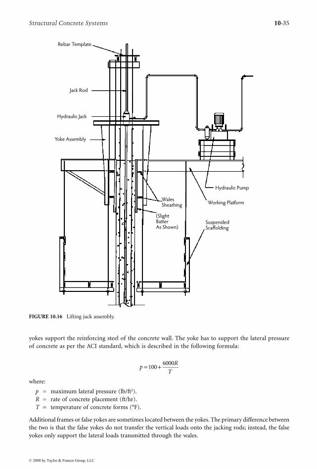
Structural Concrete Systems 10-35
yokes support the reinforcing steel of the concrete wall. The yoke has to support the lateral pressureof concrete as per the ACI standard, which is described in the following formula:
where:
p = maximum lateral pressure (lb/ft2).R = rate of concrete placement (ft/hr).T = temperature of concrete forms (°F).
Additional frames or false yokes are sometimes located between the yokes. The primary difference betweenthe two is that the false yokes do not transfer the vertical loads onto the jacking rods; instead, the falseyokes only support the lateral loads transmitted through the wales.
FIGURE 10.16 Lifting jack assembly.
Rebar Template
Jack Rod
Hydraulic Jack
Yoke Assembly
WalesSheathing
(SlightBatterAs Shown)
Hydraulic Pump
Working Platform
SuspendedScaffolding
pR
T= +100
6000
© 2008 by Taylor & Francis Group, LLC

10-36 Concrete Construction Engineering Handbook
The wales are the longitudinal supports for the sheathing. An upper and a lower wale are usuallylocated on each side of the concrete wall. More wales should be provided if the form height warrants theadditional support. Normally, this is a height exceeding 4 ft. The wales resist the loads and transfer theseloads directly to the yokes. The wales must be engineered to withstand the ACI lateral pressure requirementas indicated previously. In addition, ACI Committee 347 (2005) also requires that tolerances be maintainedfor the finished structure. The variation of wall thickness cannot be greater than ±3/8 in. for walls up to8 in. thick or ±1/2 in. for walls thicker than 8 in.; therefore, good engineering practice must be appliedin the design of these forms. As per ACI SP-4, timber wales should be a minimum of two- or three-plylumber or at least one ply of 2-in. material; when the span between jacks approaches 10 ft, the walesshould be braced to act as a truss in the vertical plane between yokes. For curved walls, the minimumdepth of segmental wales should be 4-1/2 in. at the center after cutting. Peurifoy (1995) discusses in depththe formwork for concrete structures.
The sheathing is the vertical support in direct contact with the concrete. Swelling of sheathing mustbe controlled because the sheathing is in continuous contact with moist concrete for the duration of theconstruction. Protecting sheathing prior to construction should be accomplished either by presoakinglumber or with a waterproofing preparation. In many cases, a nonabsorbtive surface that can withstandmoisture and temperature conditions is selected. Sheathing should be higher on the exterior face of theform to avoid splashing materials onto workers on the scaffolding below. As per ACI SP-4, forms shouldbe constructed of at least 1-in. board, 3/4-in. plywood, 10-gauge steel sheet, or other approved material.The sheathing, when constructed, should have a slight batter to it. This will enable the forms to self-clear. The batter should be tapered inward at the top of the form and tapered outward at the bottom ofthe form. The middle area of the sheathing is the finished dimension of the concrete wall. The height ofthe form is usually 4 ft. The sheathing is kept well oiled as it rises to eliminate excessive drag forces. Theconstruction engineer should compensate for this additional vertical load in the design.
The working platform houses all of the construction equipment necessary for the form to advance.The platform also keeps the poured walls square. Care should be taken in the design of the platform. Aminimum of 75 psf is recommended for design. In addition, concentrated buggy loads must be consid-ered. Suspended scaffolds are located below and on either side of the form. They provide a work areathat enables work crews to finish the concrete wall that has been placed. Because the concrete is still wet,it is workable.
10.11.3 Advantages and DisadvantagesOne disadvantage is that the monolithic pour precludes the placement of floors during the extrusionprocess. Horizontal reinforcing protruding through the walls cannot be placed until the slip form passesthrough the wall. Provisions can be incorporated to prepare for floors, corbels, or openings (see Figure10.17). This is accomplished by blockouts. The crews provide openings or pockets by creating formswithin the form. Quality control is of considerable importance. Care must be taken to lift the form atthe right time. As a result, the construction procedure requires skilled laborers and experienced projectmanagement. Placing concrete too quickly can result in a blowout and too slowly can cause the concreteto adhere to the form, which could damage the wall as well as the form. Construction engineering is animportant aspect of the overall procedure. Careful preparation and analysis should be undertaken priorto construction. Temperature and climatic conditions are all factors that must be incorporated in thedesign of slip-form construction. All of the above incur additional costs for the project as opposed tousing conventional forms. Another disadvantage is the difficulty of inspecting the wall, as steel is placedonly a few feet above prior to the pour. The advantage of slip-form construction is the speed at whicha wall can be erected. A slip-formed wall can eliminate up to 3 months of construction, compared toconventionally formed work, and the wall is free of horizontal joints. The taller the building, the morecost effective the system can be. The level of safety is greatly increased when utilizing the slip-formprocess. Preparation for the process must be carefully carried out by well-trained and skilled individuals.As a result, all staging is eliminated and the working areas only have to be built once.
© 2008 by Taylor & Francis Group, LLC

Structural Concrete Systems 10-37
10.11.4 Economy
Slip-forming tall cores (in excess of 12 stories) can greatly reduce the cost of construction. Only one formhas to be built which can often be reused for every level to the top. The cost of forms per contact area isgreatly reduced. The overall question of cost, however, is difficult to address due to varying costs withregional conditions, available skilled labor, and the complexity of the project. This issue must be evaluatedby the conditions that dictate the design and the location of the site.
10.12 Prestressed Concrete
10.12.1 Introduction
When gravity loads are applied to a flatwork element (slab or beam), moments and shears are createdwithin the element. Applied moments are resisted by the development of a force couple within the elementsection. The couple consists of a tension and a compression force, each occurring on opposite sides ofthe neutral axis within the section. Shears are resisted by the effective concrete area of the section; attimes, supplemental resistance is provided by shear-reinforcing steel.
In conventional concrete design, the moment-resisting couple is essentially the only resistance tobending moments; thus, the proportioning of the section dimensions, in association with the sizing ofadequate reinforcing steel, must be sufficient to resist the applied moments, with tension stresses often
FIGURE 10.17 Blockouts for floors, corbels, and openings.
Pipe Jack Rod
Pipe Jack Rod
Wall Reinforcement
Formed
Opening
Bottom of
Slip Form
Beam
Key
Bend Out Structural
Steel Bars After Slide
© 2008 by Taylor & Francis Group, LLC

10-38 Concrete Construction Engineering Handbook
being the limiting design criterion. By designing so tension stresses are resisted by mild steel reinforce-ment, the failure mode of an element will be ductile and gradual, giving ample warning of precipitatingfailure. This is ensured by designing all beams, slabs, and plates as under-reinforced; that is, the rein-forcement percentage does not exceed 75% of the balanced condition—in most cases, not more than50% to prevent congestion of reinforcement.
Pretensioned (precast) and post-tensioned concrete design, generally grouped as prestressed design,involves an additional form of resistance to the applied moments and shears. By externally applying acompressive force to the element, the stress distribution over the section is dramatically altered. Thecompressive force acting on the section reduces the tensile stresses at the tension zones, thereby preventingcracking and also increasing considerably the diagonal capacity of the section. This permits the sectionsize to be reduced while keeping the total resulting stress within the allowable range. Chapter 35 of thisHandbook gives the basic expressions for the stresses and diagrams of stress distribution across the depthof a prestressed beam as affected by the external compressive prestressing force (see also Nawy, 2003, fordetails regarding the design of prestressed concrete structures).
The use of prestressing methods can allow the designer to reduce section proportions while carryingthe same or larger load as a conventionally reinforced concrete section, which results in a correspondingreduction in cost in terms of the gross volume of concrete. The designer must acknowledge that theprestressing equipment, materials, and installation can, in some circumstances, cause the total construc-tion cost to exceed that of conventionally reinforced concrete. Preliminary cost/benefit analysis is advisablebefore deciding to use a prestressing system, provided that other requirements of span and load mightnecessitate the use of a prestressed concrete design.
10.12.2 Pretensioned (Precast) Concrete
Prestressed concrete generally falls into two groups: pretensioned or precast concrete and post-tensionedconcrete. Precast concrete usually is made in off-site casting plants and may or may not include pre-stressing. Construction elements ranging from hollow core slabs to T sections to architectural wall panelsare regularly precast. Precasting offers the controlled environment of a plant, which results in veryconsistent production in terms of quality and delivery speed. Precast plants work with heated, steel formbeds with polished form surfaces. The quality of the concrete is controlled and is usually 5000 psi orhigher. The color, consistency, and dimensions of precast elements are usually of better quality than canbe produced in the field. Concrete admixtures, to achieve rapid set and also to gain durability advantages,are frequently added to produce higher quality concrete.
As noted earlier, precast concrete can be either prestressed or not. Conventionally reinforced precastconcrete is most frequent in wall panels, columns, and miscellaneous elements such as highway dividers.Prestressed elements are most frequently produced for structures carrying high loads, bridging longspans, or subjected to harsh environments. In these cases, the precompression force improves both load-carrying performance by reducing tension stresses and durability by closing surface cracks on the tensionface that might allow the intrusion of corrosive salts or chemicals.
Where prestressing is used in precast applications, bonded prestressing is usually used. Bonded pre-stressing consists of placing high-tensile-strength (270-ksi) wire strands, or bundles, in the setting bedsprior to pouring the concrete. The strands are then tensioned by jacking them tight against a rigid frameat the head and foot of the setting bed. When the required jacking force has been introduced to thestrands, fresh concrete is poured into the bed in direct contact with the strands. As the concrete sets, thestrands become bonded to the concrete.
The initial jacking force introduced to the strand is released into the precast element via the bondbetween the strand and the concrete. This produces a fairly even distribution of compressive stress alongthe length of the member. In addition, because the bond is continuous along the length of the member,a bonded precast element can be cut into smaller pieces without losing the precompression force.
The designer is cautioned that the latter characteristic of precast concrete is only applicable where thestrand drape is flat, thus producing an even precompression force over the entire length of the element.
© 2008 by Taylor & Francis Group, LLC

Structural Concrete Systems 10-39
Where the strand drape is not flat (discussed further below), the influence of the jacking process will beto introduce both a precompression force and an internal moment into the element. In such a case,cutting the element could result in the loss of the internal moment, as it would not be resolved by thebalancing remainder of the element that has been cut away. In practice, hollow-core plank is frequentlycast in long lengths, with an essentially flat strand. The plank is then cut to the appropriate length forproject needs. Some forms of wall panel are also produced in this fashion; however, where strict qualitycontrol is required to ensure proper architectural appearance, each precast member is usually cast alone.
When designing precast concrete sections, the designer must be cognizant of several forces that acton the member during its life. It is not sufficient to simply analyze the service loads to be applied oncethe member is situated in its final position. Because concrete cures over a period of time, the relativestrength of a concrete member changes as the concrete strength increases; thus, loads that are applied toa member shortly after casting could cause stresses that exceed the capacity of the member at that specificmoment in its life.
The designer must therefore consider three types of loads that act on every precast member at somepoint. First are stripping stresses, created when the casting forms are released. This action causes suctionforces that can induce large, concentrated tensile stresses in the concrete. Second are transport stresses,created from lifting and stacking the members for transport around the casting yard and to the job site.Lifting lugs are frequently cast into the precast members to provide a location for the attachment oflifting equipment. The use of strategically located lifting lugs allows the designer to anticipate and designfor the stresses that result from moving the members. Last are service stresses, which occur as a resultof the design loads that are expected to act on the structure, determined by its use classification. Theseare the traditional design loads that must always be addressed.
When precast elements arrive at the job site, they are erected piece by piece and bearing pads are usedto separate the elements. Precast concrete shop drawings specifically detail all of the connections betweenthe precast pieces and any other structural members. Local stress concentrations must be taken intoconsideration during the design process to address conditions where ledges or corbels will supportadjoining members.
In certain applications of precast concrete, a final cast-in-place concrete topping is applied when theprecast superstructure has been erected. This is typical in precast plank or double-tee construction, wherea consistent, durable wearing surface is required. The topping course (typically, 2 to 3 in. thick) issometimes reinforced with welded wire fabric, thus providing catenary reinforcement, which aids in thedistribution of loads over the entire floor system.
10.12.3 Post-Tensioned Concrete
While pretensioning is generally conducted in a plant setting, post-tensioning is mostly conducted in thefield. The “post” term is something of a misnomer, as the precompression force introduced into theconcrete is added prior to the introduction of any load on the structural system. The term has evolved,however, because the procedures occur at the construction site rather than at a precasting plant and thusare “post” because the members are not brought to the site ready to install. Post-tensioning design followsthe same procedures and expressions used in the design of pretensioned elements except for prestresslosses. By introducing a precompression force into the concrete section, the maximum tensile stress isreduced by the compressive stress, thereby permitting the use of smaller sections that support the sameloads as conventionally reinforced concrete members. Construction procedures can be considered anextension of those used in traditional cast-in-place (situ-cast) concrete. Formwork must be erected tosupport the fresh, poured concrete; mild reinforcing steel must be placed to provide system ductility;and site curing procedures must be followed to ensure that quality, final concrete is produced. Theconcrete stresses permissible in flexural prestressed members occur at three load levels: stresses occurringimmediately after prestress transfer, stresses at service load, and stresses at the ultimate load level. Section18.4 of the ACI 318-05 Code presents the permissible stresses at the extreme fibers of the members forthese loading stages. Also, Chapter 11 and Chapter 12 in this Handbook and Prestressed Concrete: A
© 2008 by Taylor & Francis Group, LLC

10-40 Concrete Construction Engineering Handbook
Fundamental Approach by Nawy (2003) address most of the design and construction aspects pertinentto pretensioning and post-tensioning beams and one-way and two-way slabs and plates. It is importantto recognize that, in two-way slab design, attention must be given to re-entrant corners, large openings,L-shaped plan configurations, balconies, repetitive perimeter openings, or steps in slab elevations. Eachof these conditions poses a difficult design problem if conventionally reinforced concrete is used. Theproblems are multiplied when the system is precompressed and compelled to shorten. Cracks can rapidlydevelop at corners, and localized crushing of concrete can occur, particularly due to stress concentrationat these locations. To counter this condition, significant mild steel reinforcement has to be provided toprevent cracking propagation at the early stages of post-tensioning or loading.
Acknowledgments
This is a revised and updated version of the original text, which was authored by the late Terry O.Blackburn, P.E., Ph.D., former Principal and Director, Structural Department of Schoor DePalma, Engi-neers and Consultants, Manalapan, New Jersey. The author wishes to extend deep appreciation to D.Matthew Stuart, P.E., S.E., F. ASCE, SECB, and Delcho Palechev for their contributions to updating thechapter and to all of the author’s coworkers at the Structural Department of CMX, Inc.
References
ACI Committee 224. 2001. Control of Cracking in Concrete Structures, ACI 224R. American ConcreteInstitute, Farmington Hills, MI.
ACI Committee 318. 2005. Building Code Requirements for Structural Concrete, ACI 318-05 and ACI318R-05. American Concrete Institute, Farmington Hills, MI.
ACI Committee 347. 2005. Formwork for Concrete Handbook, 7th ed., SP-4. American Concrete Institute,Farmington Hills, MI.
ACI Committee 352. 2002. Recommendations for Design of Beam–Column Connections in MonolithicReinforced Concrete Structures, ACI 352R. American Concrete Institute, Farmington Hills, MI.
ACI Committee 372. 2003. Design and Construction of Circular Wire- and Strand-Wrapped PrestressedConcrete Structures, ACI 372R. American Concrete Institute, Farmington Hills, MI.
ACI Committee 373. 1997. Design and Construction of Circular Prestressed Concrete Structures withCircumferential Tendons, ACI 373R. American Concrete Institute, Farmington Hills, MI.
AISC. 2005. Steel Construction Manual, 13th ed. American Institute of Steel Construction, Chicago.ASCE. 2005. Minimum Design Loads for Buildings and Other Structures, SEI/ASCE 7-05. American Society
of Civil Engineers, Reston, VA.ASTM. ASTM Standards C33, C150, C311, C494, C618 (referred to in the text). American Society for
Testing and Materials, Philadelphia, PA.Billington, D.P. 1982. Thin Shell Concrete Structures. McGraw-Hill, New York.ICC. 2006. 2006 International Building Code. International Code Council, Washington, D.C.Nawy, E.G. 2003. Prestressed Concrete: A Fundamental Approach, 4th ed. Prentice Hall, Upper Saddle
River, NJ.Peurifoy, R.L. 1995. Formwork for Concrete Structures, 3rd ed. McGraw-Hill, New York.PCA. 1992. Circular Concrete Tanks Without Prestressing. Portland Cement Association, Skokie, IL.PCA. 1998. Rectangular Tanks. Portland Cement Association, Skokie, IL.Russillo, M.A. 1988. Forming economical concrete buildings: lift-slab construction—its history, meth-
odology, economics, and applications. In Proceedings of the Third International Conference. ACI/ASCE/TMS, Farmington Hills, MI.
Timoshenko, S. and Woinowsky-Krieger, S. 1959. Theory of Plates and Shells. McGraw-Hill, New York.Young, W.C. 1989. Roark’s Formulas for Stress and Strain. McGraw-Hill, New York.
© 2008 by Taylor & Francis Group, LLC

(a) Float-in dam segment for Braddock Dam on the Monongahela River upstream of Pittsburgh, Pennsylvania.(Photograph courtesy of U.S. Army Corps of Engineers.) (b) Segment erection for the new San Francisco Bay BridgeSkyway Segment. (Photograph courtesy of KFM Constructors Joint Venture.)
(a) (b)
© 2008 by Taylor & Francis Group, LLC