structural deflections: a literature and state-of-the-art
TRANSCRIPT

BUILDING SCIENCE SERIES 47
Structural Deflections.
A Literature and
State-of-the-Art Survey

The Building Science Series
The Building Science Series disseminates technical information developed at the National Bureau of Standards on
building materials, components, systems and whole structures. The Series presents research results, test methods and
performance criteria related to the structural and environmental functions and the durability and safety characteristics
of building elements and systems.
These publications, similar in style and content to the NBS Building Materials and Structures Reports, (1938-59),
are directed toward the manufacturing, design, construction and research segments of the building industry, standards
organizations and officials responsible for building codes.
The material for this Series originates principally in the Building Research Division of the NBS Institute for Applied
Technology. The publications are divided into three general groups: Building Systems and Processes; Health, Safety,
and Comfort; and Structures and Materials. Listed below are other publications in the category of
—
Structures and Materials
• Interrelations Between Cement and Concrete Properties: Part 1, Materials and Techniques and Trace Elements
(C13.29/2:2) 35 cents
• Weather Resistance of Porcelain Enamels: Effect of Exposure Site and Other Variables After Seven Years (C13.29/2:4)
20 cents
• Interrelations Between Cement and Concrete Properties: Part 2, Sulfate Expansion, Heat of Hydration, and Autoclave
Expansion (C13.29/2:5) 35 cents
• Some Properties of the Calcium Aluminoferrite Hydrates (C13.29/2:6) 20 cents.
• Organic Coatings, Properties, Selection, and Use (C13.29/2:7) 12.50
• Interrelations Between Cement and Concrete Properties: Part 3, Compressive Strengths of Portland Cement Test
Mortars and Steam-Cured Mortars (C13:29/2:8) 35 cents
• Thermal Shock Resistance for Built-Up Membranes (013.29/2:9) 20 cents
• Shrinkage and Creep in Prestressed Concrete (013.29/2:13) 15 cents
• Experimental Determination of Eccentricity of Floor Loads Applied to a Bearing Wall (013.29/2:14) 15 cents
• Interrelations Between Cement and Concrete Properties : Part 4, Shrinkage of Hardened Portland Cement Pastes
(013.29/2:15) 75 cents
• Causes of Variation in Chemical Analyses and Physical Tests of Portland Cement (013.29/2:17) 40 cents
• A study of the Variables Involved in the Saturating of Roofing Felts (013.29/2:19) 30 cents
• Proceedings of a Seminar on the Durability of Insulating Glass (013.29/2:20) 75 cents
• Hail Resistance of Roofing Products (013.29/2:23) 25 cents
• Natural Weathering of Mineral Stabilized Asphalt Coatings on Organic Felt (013.29/2:24) 30 cents
• Structural Performance Test of a Building System (013.29/2:25 11.25
• 1964 Exposure Test of Porcelain Enamels on Aluminum—Three Year Inspection (013.29/2:29) 25 cents
• Flexural Behavior of Prestressed Concrete Composite Tee-Beams (013.29/2:31) 25 cents
• Compressive Strength of Slender Concrete Masonry Walls (013.29/2:33) 40 cents
• Strength of Masonry Walls Under Compressive and Transverse Loads (013.29/2:34) 70 cents
• Interrelations Between Cement and Concrete Properties: Part 5, Freezing and Thawing Durability, Saturation, Water
Loss and Absorption, Dynamic Modulus (013.29/2:35) 11.25
• Interrelations Between Cement and Concrete Properties : Part 6, Compilation of Data from Laboratory Studies
(013.29/2:36) $1.25
• 1939 Exposure Test of Porcelain Enamels on Steel, 30-Year Inspection (013.29/2:38) 25 cents
• Engineering Aspects of the 1971 San Fernando Earthquake (013.29/2:40) S3.00
• Paper Honeycomb Sandwich Panels at Lighweight Structural Components (013.29/2:43) 25 cents
• Full Scale Test on a Two-Story House Subjected to Lateral Load (013.29/2:44) 50 cents
Send order (use Superintendent of Documents Catalog Nos.) with remittance to:
Superintendent of Documents, U.S. Government Printing Office, Washington, D.C. 20402.
Remittance from foreign countries should include an additional one-fourth of the purchase price for postage.
[See mailing list announcement on last page.]

Structural Deflections.
A Literature andState-of-the-Art Survey
^O\[d\i-0^ ^\f,f\C€. - National Bureau of Sta:n(Sard$
' ^ ' ^ MAY S 1374
T, V. Galambos, P. L. Gould,
M. K. Ravindra, H. Suryoutomo,
Civil and Environmental Engineering Department
Washington University
St. Louis, Mo. 63130
and
R. A. Crist
Center for Building Technology
Institute for Applied Technology
National Bureau of Standards
Washington, D.C. 20234
U.S. DEPARTMENT OF COMMERCE, Frederick B. Dent, Secretary
NATIONAL BUREAU OF STANDARDS, Richard W. Roberts, Director
Issued October 1973

Library of Congress Catalog Number: 73-600282
National Bureau of Standards Building Science Series 47
Nat. Bur. Stand. (U.S.), Bldg. Sci. Ser. 47, 104 pages (Oct. 1973)
CODEN: BSSNBV
For sale by the Superintendent of Documents, U.S. Government Printing Office, Washington, D.C. 20402
(Order by SD Catalog No. C13.29/2:47). Price S1.25

6l Conversion Units
In view of the present accepted practice in this country for buildingtechnology, common U. S. units of measurement have been used throughoutthis paper. In recognition of the position of the United States as a signatoryto the General Conference on Weights and Measures, which gave officialstatus to the metric SI system of units in 1960, assistance is given tothe reader interested in making use of the coherent system of SI unitsby giving conversion factors applicable to U. S. units used in this paper.
Length
1 in 0.0254 meter (exactly)
1 ft 0.3048 meter (exactly)
Mass
1 lb (Ibm) = 0.4536 kilogram
Force
1 kip 4448 newton
Stress
1 psf 47.88 newton/meter 2
iii


TABLE OF CONTENTS
Page
SI Conversion Units iii
1. Introduction 1
2. Background 2
3. Static Deflections 7
3.1 General 7
3.2 Effects of Deflections on Structures 7
3.3 Quantitative Limitations on Deflections 8
3.4 Computation of Deflections 10
3.5 Field Observations 11
4. Dynamic Deflections 12
4.1 General 12
4.1.1 Current Design Practice . 12
4.1.2 Forcing Functions 14
4.1.3 Structural Systems 15
4.1.4 Natural Frequency 16
4.1.5 Damping 17
4.1.6 Damage to Structures 18
4.1.7 Vibration Isolation 19
4.2 Floor Vibrations 20
4.2.1 Introduction 20
4.2.2 Analytical and Experimental Studies on Floor Systems . 20
4.2.3 Experiments on Steel Joist Floor Systems (Lenzen). . . 22
4.2.3.1 Dynamic Response Experiments 22
4.2.3.2 Damping 24
4.2.3.3 Conclusions 25
4.3 Drift 26
4.3.1 Effects of Lateral Loading on Structures 26
4.3.2 Quantitative Limitations on Drift 27
4.3.3 Calculation of Drift 28
V

4.3.4 Measurements of Drift Deflection 29
4.4 Human Perception and Response to Motion of Structures 31
4.4.1 Previous State-of -the-Art Reviews 33
4.4.2 Physiological Responses 34
4.4.3 Subjective Responses of Humans 34
4.4.4 Observed Human Response 36
4.4.5 Vibration Clauses in Standards 39
4.4.6 Comparison of Data for Human Response to Structural
Vibrations 41
4.5 Discussion 49
5. References 50
Appendix A, Summary of Vertical Deflection Limitations in U. S.
Codes and Standards 67
Appendix B, Summary of Vertical Deflection Limitations in Foreign
Codes and Standards 79
Appendix C, Steel Floor Joist Vibration Formulas Developed by Lenzen . 93
vi

Structural Deflections
A Literature and State -of -the -Art Survey
T. V. Galambos, P. L. Gould, M. K. Ravindra, H. Suryoutomo
,
and
R. A. Crist
A literature survey and state-of-the-art study was compiled usingapproximately 225 primary source documents, research papers and texts.Over 800 documents were scanned to arrive at the primary source documents.The problem of structural deflections is discussed and reviewed in itscomponent areas of static and dynamic deflections as related to forcingfunctions and structural characterisitics . Also the interactions of majorstructural deflections with building structures subsystems and humanoccupants is reviewed. Emphasis is placed on serviceability limit statesof deflections. Detailed comparisons of human response to structuralvibrations are also made. This report is broad in scope and covers theareas of analysis, design and experimentation.
Key Words : Analysis; deflection; design; dynamic; experimental; humansensitivity; loading functions; specifications; static; structural engineering;subsystems; vibration.
1. Introduction
This literature survey and state-of-the-art study* encompasses a
broad area of the structural engineering field; deflections of buildingstructures. Other types of structures such as tov\rers
,bridges, etc.
are briefly mentioned but primarily in the context of information thatmay be applicable to building structures. This study was compiled usingapproximately 225 primary source documents, research papers, and texts.Over 800 documents were scanned to arrive at the primary source document.
The report was assembled considering building structure deflectionin a sequence that would be used when considering the solution of a structuraldeflection problem, i.e., separation of static and dynamic deflectionsand then considering each of these as a three component problem of load--structural characteristics - -response (deflection]. This sequence isdeveloped and defined for the respective components throughout the report.Also the interactions of major structural deflections with building structuressubsystems and human occupants is reviewed.
In this report an attempt is made to identify serviceability criteriafor the present practice of building construction, to determine the theoreticaland experimental basis for these requirements and to evaluate the range ofapplicability of the existing criteria. Primary emphasis is on theidentification and documentation of existing serviceability provisions. Thebibliographical listings are not necessarily a listing of all availableliterature but rather a listing of what vas considered by the authors tobe the most pertinent. This report is broad in scope and covers the areasof analysis, design and experimentation.
* Research sponsored by the Office of Policy Development and Research,Department of Housing and Urban Development, V/ashington , D. C. 20410.

2 . Background
In design and construction in the past, deflections have beenrelatively small compared to member sizes or average building size, thus,they have not been a dominant concern for the structural designer. Withinthis decade the rapid increase of building construction costs have beenpressing the industry for more economical methods of construction; newmaterials have become available which result in low effective materialmodulus and overall reduced structural stiffness; and more sophisticated andaccurate methods of design and analysis are being used. For these reasonsdeflections have become more significant than in the past with respect todesign control. Serviceability limit states have become progressivelymore important. With an emphasis on serviceability, the structural designeris confronted not only with a more complex situation of designing fordeflection as well as strength, but, he is also required to solve aninterdisciplinary problem. Serviceability of a building structure hasa direct correlation to the comfort of the occupants of a structure.The aspects of human comfort as related to structural deflection involvethe knowledge of psychologists, bioengineers , the medical profession,only to name a few. Professionals with diverse backgrounds such as structuralengineers and psychologists have to find a common ground of communicationso that problems can be rationally approached. New vocabularies in eachfield have to be mastered and understood.
Structural deflections are difficult to discuss unless they arebroken down to more specific subjects. For this report serviceabilityis of primary concern. A serviceable structure is a structure whichmeets the needs for which it is intended in everyday use. Deflectionsof a structure at a serviceable level are not generally those deflectionswhich occur at a collapse or an ultimate limit state. Some brief mentionof deflections at ultimate limit states will be made in this report withrespect to ductility as it applies to life safety and earthquake loading.However, most of the emphasis ^^rill be on serviceability referenced tosmall recurrence interval loadings and to continued functional use ofa structure.
The problem of deflections in building structures as viewed in thisreport is divided into components as shown in figure 1. The primarydivision is the separation of static and dynamic deflections. Traditionally,many dynamic structural design problems were reduced to a pseudo dynamicproblem by use of "equivalent" static loads. Advancement of technologynow permits the actual consideration of the dynamic structural problem.The primary difference between the static and dynamic problem is theconsideration of the dimension of time in the dynamic case. Dynamicdeflections corresponding to dynamic loads are time dependent, i.e.,they have a describable time history. Strictly speaking for the generalcase, all loads and deflections are time dependent and thus dynamic.Hov;ever, in the more practical sense, if time parameters of loading andstructural characteristics are considered, a difference can be made betxveenthe static and dynamic cases. A static load, thus causing a static deflection,is one which is sloA'/ly applied and released. Slowly refers to the durationof time of application and release of load compared to the natural periodof the structure. If the ratio of load application or release durationto natural period is large, the load and corresponding deflection canbe considered static. Conversely, if the ratio of load application orrelease duration to natural period is small, the load and correspondingdeflection are dynamic and the dimension of time has to be considered.'It also can be stated that in the dynamic case, inertial forces are significantand must be considered to create dynamic equilibrium. An order of magnitudeestimate for static and dynamic loads which cause corresponding staticand dynamic deflections in building structures can be given. Dynamicloads are applied and released in the order of seconds or less whereas
2

z in
o >
O CO
I- I-O Q-UJ LlI
_l O
10
c•H+-J
uoI—!
oo
^
t 2 o
tou- u- t;;>-iij iij
coo Q
I-o<LUH
34-J
O3
CO
6V
CO
to
q:ljj
coo
COCOliJ
1 CO
>:qco
6
c
t CO
< Q.<UJ Z>lii
, Q COQ,
IO
UJ
O COQ ZZ << cca:
UJ
o
I-co
oUJ_Iu.UJQ
3

static loads are applied or released in the order of minutes or greaterAnother type of dynamic, i.e., time dependent load, has to be consideredin a greater order of magnitude time domain. Long term, in the orderof months and years, deflections due to sustained (static) loading attributedto creep of the constituent materials of the structure are important to
the serviceability of a structure. These deflections are more accuratelyunderstood by the study of the constituent materials. The subject ofcreep deformations is important but due to the scope of this work has*not been emphasized in this report.
Once the differentiation is made between static and dynamic deflections,it becomes clear why traditional deflection design requirements are inadequatein a general sense. The structural design practice has been dominatedby deflection criteria such as ; the vertical deflection of a beam orfloor for a given load shall not exceed the span divided by 360, or thehorizontal deflection of a high-rise structure subjected to a lateralload shall not exceed 0.002 times the total height of the structure.In the case of the requirement for floors and beams where occupants areresponding to a time dependent deflection, the L/360 criterion has littlerational justification. It has been adequate in the past because ofthe relatively stiff floors using high effective modulus materials. Nowthat new materials (lower moduli and higher stresses) and more flexiblesystems are being used, the dimension of time has to be considered inthe deflection criteria. In the case of the lateral deflection criteria,pseudo dynamic loads (equivalent static loads) have been used to calculatedeflections from structural analysis methods which did not consider thedynamic properties of the structure and did not consider all elementsof the structure which contribute to its stiffness. This causes a two-way confusion. The loading is not realistic and the analysis model ofthe structure is inaccurate, thus, a deflection criterion on this basishas as its only rationale that it has been adequate through experience.When past experience is somewhat nullified by changes in structural designmethods and materials, the deflection criteria then becomes inadequate.These two typical deflection requirements have been used as a panaceafor a very complex aggregation of design considerations. They shouldnot be expected to be broadly applicable.
Further breakdoim of each of the static and dynamic deflectionproblems can be made. Considering the static deflection problem, possiblythe less complex of the t^vo , the problem can be stated in engineeringterms as shown on figure 1.
ipj=[K][yj
From a given load,[p] , and given structural characteristics, [K] , a systemdeflection, (yj , can be determined. Alternatively, with two of the threecomponents of the problem known the other can be determined. The fourthcomponent of this engineering statement is interaction with the occupantsof the structure and the subsystem, (figure 1). It is by far the mostcomplex and difficult to define of tlie four components. The subsystemsconsidered are the partitions, windows, doors, mechanical equipment,etc. Human response is expressed in subjective terms such as "desirable"and "undesirable" A^?hich are difficult to define. Even though the subsystemresponse is objective, it has not been clearly defined in the past whatsystem response characteristics affect the function of the subsystems.
The dynamic deflection problem is shown on figure 1. It can be expressedin block diagram from as
F(t) G(t) Y(t)
In general terms, the major components are; the dynamic load or forcingfunction, F(t), the structural characteristics or transfer function.
4

G(t), and the system response, Y(t). If two of the three components areknown, the other can theoretically he determined. Analysis leading to
design involves a designated forcing function and a calculated transferfunction to determine the system response. Measurements of system response(deflection of a structure in service) allow a reverse process, i.e.,_
the structural characteristics can he determined if the forcing functionis known or the forcing function can he inferred if the structuralcharacteristics are known.
The forcing function can be random or transient such as that createdby foot traffic or vehicles. Steady state loading is generally causedby reciprocating mechanical equipment; wind load is both random and transientbut it is referred to here separately because of its importance. Earthquakeloading is also random and transient, however, as previously mentioned,this type of loading will not be considered extensively. It is applicableto the ultimate limit state more than the serviceability limit state.The possibility should not be overlooked that small recurrence interval,low intensity earthquakes could be considered in the category of serviceability.
Dynamic structural characteristics involve the identification ofthe natural frequency of a structure (mass and stiffness) and damping.The dynamic structural characteristics are more complex than just determiningthe natural frequencies of a structural frame. The dynamic structuralcharacteristics are the properties of the entire structure which interact(in the mechanical as well as the mathematical sense) with the forcingfunction to result in a structural system response. Non - structural elements(partitions, walls, etc.) have a significant effect on these properties.Also it is possible that the interaction of the structure and its foundationmay effect the structural characteristics. The system response is a timedependent deflection.
Similar to the static deflection problem, there is an interactionof the dynamic system deflections (figure 1) with the human occupants(human response) and subsystems. Human response is considered in threegeneral divisions, whole body vibration, audial and visual. Whole bodyvibration is a general category which does not designate the specificcues that sense whole body vibration. Specific cues are the local excitationof internal organs, inner ear, skin, bone, muscle, etc. Human sensitivity(figure 1) has been found to cover a wide range of motion parameterssuch as acceleration, velocity, damping and total duration of vibrationexposure. The classification of human response parameters in termsof quality of response start at a perception threshold and cover a rangeto an intolerable or damaging level of vibration. The environment ofa human while responding to vibration is another important variable affectingthe quality of human response to vibration. Visual response to vibrations,such as the sway of high-rise structures observed from one structureto another or the local motion of equipment within a structure, affectsthe human response. Audible response to vibrations such as the creakingof a structure or the banging of elevator counterweights is also a factorto be considered in human response.
Subsystem response is a parallel area of concern in the dynamicinteraction problem. The system deflections must allov; for the properfunctioning of the subsystems. Measures of the proper functioning ofthe subsystem are local damage and serviceability.
This breakdown of the structural deflection problem is principallyconcerned with serviceability. It has divided the problem into its majorcategories to lead to a rational approach of the problem. Some of thesecategories have been studied extensively and major contributions havebeen made to the technology. Other areas have had fragmented or limitedstudy and require further research and assimilation. Subsequently, thisreport v/ill elaborate on the details of this problem breakdown as shown
5
i
in figure 1. As the literature is reviewed, it will be evident wheregaps of knowledge exist. These points will be discussed individuallywithin each section.
It is appropriate to point out how a rational understanding of thestructural deflection problem shown in figure 1 can lead to a properly-designed structure with respect to deflections. The understanding andsolution of the interaction problems lead to allowable deflections. Theiteration loop of design applicable to deflections is then completed.It is formed by three major components; structural characteristics, specifiedload, and allowable deflection.
Many different deflection criteria would be required for satisfactorybehavior if all probable loading situations are considered for a particularstructure. Several are evident from figure 1.
Static system deflection is controlled to limit:
human response to static deflection
subsystem response to static deflection
Dynamic system deflection is controlled to limit:
dynamic whole body vibration
audible perception of motion
dynamic visual perception to motion
dynamic subsystem response.
Although these are not all that are possible, they appear to bethe major categories. Each case can result in a deflection requirement.It is possible that each structure is unique with respect to which ofthese cases will be significant. Categories may be combined as more islearned of each. Again, it is evident why a single deflection specification,which was derived from tradition without rationale, cannot be expectedto result in adequate deflection criteria.
6

3. Static Deflections
3 . 1 General
This section covers the computation, measurement and the assessmentof the effects of static deflection on structural systems and subsystems.Those deflections which are associated with lateral building movementare discussed separately in Section 4.3. Appendices A and B includea summary of various code requirements with explicit reference to therespective codes.
3. 2 Effects of Deflections on Structures .
The possible undesirable effects of excessive structural deflectionshave been noted by Allen [2]*, These effects include 1) cracking ofprimary structural members which may provide a means for the transmissionof unwanted sound, moisture and cold air and promote corrosion, as wellas being unsightly; 2) cracking or crushing of non-structural componentssuch as partitions; 3) lack of fit of doors and windo\\rs
; 4) walls outof plumb; 5) eccentricity of loading due to rotation; 6) unsightly droopiness;and 7) ponding. Allen suggests that many deflection-caused problemscan be alleviated by alternate design solutions such as flexible joints,etc
.
The American Concrete Institute (ACT) Committee 435 report [1] liststhe following reasons for limiting deflections: 1) Sensory acceptability(visual, tactile, auditory); 2) Serviceability of structure (surfaceswhich should drain water, floors v/hich should remain plane, members supportingsensitive equipment): 3) Effect on nonstructural elements (walls, ceilings,adjacent building elements supported by other members); 4) Effect onstructural elements (deflections causing instability of primary structure,deflections causing different force system or change in stresses in someother element, deflections causing dynamic effects). In this reportexamples of each of the items noted are given along with deflectionlimitations
.
A comprehensive examination of the effect of deflections on st:fucturesis coi;Ltained \n the report. Deformations, Committee No. 4 of ComiteEuropeen du Beton [8]. In this report, the effect of deflections onstructures are separated into deflections which do and do not effectthe overall stability of structures. Those deflections which affectthe structural stability are further classified into 1) static; and 2)dynamic effects. Those deflections which do not affect structural stabilityare classified as 1) psychological or esthetic effects; 2) effects whichmay produce damage in other non load-bearing structural units; 3) indirecteffects on the stability of other structural members or structures; and4) effect of deflections on the serviceability of the structure.
The American Institute of Timber Construction Standard [19] statesthe reasons why a deflection limitation requirement is desirable: 1)Possible damage to attached or connected materials such as plaster androofing; 2) Effect on the function of the completed structure such as
* Numbers in brackets refer to literature references. References aregrouped in the respective report sections and are listed in alphabeticalorder in each section.
7

vibration and springiness; 3) The acceptable final shape or positionof the completed structure or nenber such as roof pitch and pocketsaffecting drainage or interior appearance; and 4) Effect on door clearancesor effect on sash and glass lielow a member.
For wood floor structures, Vermeyden [20] had traced the requirementsfor deflection limitations to a prevention of 1) sagging or crackingof ceilings and jamming of doors; and 2) discomfort. He discusses theeffect of long-term deflection as well as instantaneous elastic deflections.
With regard to aluminum structures , the Report on the StructuralUse of Aluminum by the Institution of Structural Engineers [14] statesthat the deflection of a member shall not be such as to impair the strength,functioning or appearance, or to cause damage to the finish of any partof the structure.
Some structural deflection phenomena are o^^ten long-term time-dependentand consequently may become evident only after some years. As such,the construction sequence, inelastic material properties, climatic effectsand pattern of usage may determine if a given structure ivill suffer fromdeflection induced problems. Furthermore, when the designer considersthe relative importance of deflection criteria in building design, heshould discern between those factors which can lead to catastrophic failure,such as ponding and corrosion, as opposed to those items which simplycause inconvenience, such as jammed windows. A quantifiable method ofdiscerning between failure and unserviceability type criteria has beennoted by Davenport [7] .
3 . 3 Quantitative Limita tions on Deflections .
Quantitative limitations on deflections are most often given in termsof a fraction of the span length, L. A summary of this type of limitationis given by Allen [3] . In this commentary on the various standards pertinentto the National Building Code of Canada, 1970, various types of roof, floorand wall members are considered along with the most used constructionmaterials, timeber, reinforced concrete, steel and aluminum. The generalrange of values is from L/18n to L/360. These deflection limitations referto dead load, live load, creep and ponding deflections when applicable.Represenative specific values are given in Appendix B.
An early study (1948) of the behavior of houses was done by Whittemoreet al at the National Bureau of Standards [21] . Insight of these authorswas expressed through the realization that the the L/360 limitation wasquite arbitrary. Absolute limitations of deflection for various typesof loading (compressive, transverse, concentrated, impact and racking)and elements (walls-load and non-load bearing, floors and roofs) aregiven. As an example, for transverse loading on floors, 2-inches ofdeflection is allowed for a 40 Ib/ff^ superimposed static load. Alsoa permanent set, for the same condition, of 1-inch is allowed. The rationalefor these large allowable deflections is that the actual loading on thefloor may not be more than 8 Ib/ft^. Many qualifications would have tobe made before this type of criteria could be used.
A comprehensive summary of deflection limitations for reinforcedconcrete construction is provided in the ACI Committee 435 report [1].In this report, deflection limitations are given for the various classificationsnoted in the previous section. The limitations are given in the usualfraction of span but, in addition, absolute deflection limits are specifiedwith respect to the effect of deflections on non-structural elements.Also, the rationa:ie of using the depth/span ratio as an indirect quantitativeindex of allowable deflection is developed. A notable feature of thesuggested limitations is the specification of the portion of the totaldeflection upon v/hich each limitation is based.
8

A great many state and local codes in the United States incorporatethe Building Code Requirements for Reinforced Concrete, ACI 318-71 [2];the Specification for the Design, Fabrication and Erection of StructuralSteel, AISC [11]; the American Institute of Timber Construction Specification,AITC [19] ; the Specifications for Aluminum Structures [4] ; and the StandardSpecifications and Load Tables of the Steel Joist Institute, SJI [16].These standards thus should reflect the general state-of-the-art practicewith respect to these building materials. The pertinent deflection limitationsare summarized in Appendix A and are discussed in the subsequent paragraphs.The model codes summarized in Appendix A also incorporate these provisions.A comparative review of the model codes is give by Buchert, Mulner andRubey [6] .
The ACI Building Code gives deflection limitations in terms of afraction of the span for the following member types: 1) Flat roofs notsupporting or attached to non -s tructural elements likely to be damagedby large deflections; 2) Floors not supporting or attached to non- structuralelements likely to be damage by large deflections; 3) Roof or floor constructionsupporting or attached to non-structural elements likely to be damagedby large deflections ; and 4) Roof or floor construction supporting orattached to non -structural elements not likely to be damaged by largedeflections. As a second means of controlling deflections, minimum thicknessrequirements are provided for solid one-way slabs , ribbed one-way slabsand beams which are not supporting or attached to partitions or otherconstruction likely to be damaged by large deflections. Also, miminumthickness requirements are provided for nonprestressed two-way construction.
The AISC specification states that beams and girders supportingfloors and roofs shall be proportioned with due regard to the deflectionproduced by the design loads but only specifies a quantitative limitationof L/360 for members supporting plastered ceilings. Ho\>:ever, in thecommentary, guidelines are suggested for the depth/span ratio as a functionof the yield point stress, F as a means for controlling deflection.For fully stressed beams and^girders in floors , the suggested value ofthe depth ratio is F /800 while for roof purlins F /lOOO (excluding flatroofs) is given. ^ ^
Another deflection-related phenomenon treated in detail by the AISCspecificication is ponding, defined therein as the retention of waterdue solely to the deflection of flat roof framing. The code provisionsare based on the spans and moments of inertia of both the primary andsecondary members and of the steel deck supported on secondary members.These relations are based on equations given by Marino [12]. In addition,graphical design aids are provided in the commentary when a more exactdetermination of required flat roof framing stiffness is required. TheAISC specification also limits the total bending stress to 0.80 F inprimary and secondary members due to the weight of the ponded water plusdead and gravity live loads. It is noted that stresses due to wind orseismic forces need not be included in a ponding analysis.
The AITC specification requires the simultaneous satisfaction ofdeflection limitations of L/240 for total load and L/360 for live load.
The Specification for Aluminum Structures suggests the use of theeffective width concept when deflection at design loads is critical.
The SJI specification give deflection limitations of L/360 for floorsand roofs with plastered ceiling attached or suspended and L/240 forother roofs.
A comparison of European standards and specificatipns for , reinforcedcpncrete is provided by the Committee 4 report of Comite Europeen duBeton [8] where information from Austria, Belgium, Switzerland, Germany,
9

Denmark, Spain, England, Italy, Portugal, Poland, Sweden, Turkey and
Yugoslavia is presented. The information from this report regarding allowable
limits of deformation is included in Appendix B.
A survey of European and North American practice for timber membersis provided by Vermeyden [20]. In addition to the Dutch regulationsfor the limiting deflections of wood beams, he also surveys those fromGermany, Switzerland, Austria, Denmark, France, Great Britain and Canada.He notes that in all cases the limitations are based on elastic deflectionsbut that total load is used in some cases while live load is used in
others. The specific deflection limitations contained in this paperare summarized in Appendix B.
Another literature survey with similar information to that containedin Vermeyden's report was conducted by Onysko [13]. Deflection limitationsfrom this report are given in Appendix B.
3 . 4 Computation of Deflections
.
When numerically computed values of deflections are specified andpresumably correlated with the presence (or absence) of certain undesirableeffects in buildings, it is preferable to have a rational and standardizedbasis of computation. The possibility for achieving this standardizationis dependent on the complexity of the structural framing system includingconnections, foundations and the materials of construction.
With respect to the problems introduced by complex framing systemsand the ensuing representation by the mathematical model for which thedeflections are computed, an example of the poor correlation betweencomputed and observed deflections of a structural frame is reported byWiss and Curth [22]. Section 4.3 discusses the available computer-basedtechniques of structural analysis which enable improved m.athematicalmodels of structures to be considered.
The problems introduced by constituent material considerations areprincipally encountered in the computation of deflections for reinforcedconcrete members and structures. These problems are enumerated in greatdetail in ACI Committee 435 report [1] and appear to be a result of severalfactors: 1) the assumption that concrete carries no tension for strengthcalculations which may be unduly conservative for deflection calculations;2) the assessment of the end restraint introduced by monolithic construction;3) the non-linear material behavior in the working load range prior toand beyond cracking; 4) the historical sequence of loading includingconstruction and load test sequences; 5) the contribution of the transformedare-a of the reinforcing steel to the stiffness in uncracked sectionsand the contribution of the compression steel to the stiffness in crackedsections; and 6) long-term deflections due to shrinkage and creep. Thedifficulties involved in considering any one of these factors makes theprecise determination of deflections in reinforced concrete structuresa somewhat academic exercise which suggests that limitations on computeddeflections should be rather broad.
With respect to European practices, a comparative study of variousassumptions for elastic modulus, effect of sustained loading ai;id effectivemomeijit of inertia is contained in Committee 4 report of Comite Europeendu Beton [8] along with some suggested overall methods of computing deflections.
For timber structures, creep under sustained load must also be consideredin addition to elastic deformations. A method for computing deflectionsin timber structures including creep effects is pronosed by' Vermeyden
in

With regard to structures constructed nf structural steel or aluminum,it appears that the accepted methods of elastic analysis ^re applicablewith the basic assumption of linear elastic behavior in the working loadrange. Some further elaboration, however, is needed for steel structuresdesigned by the method of plastic design. Since this method considersthe structural behavior at the collapse load and many of the deflectionlimitations found in the various codes are based on structural serviceabilityat working loads, the determination of deflections prior to the formationof the "last hinge" and collapse will not usually be sufficient to checkserviceability criteria. This aspect of plastic design has been investigatedby the Joint WRC-ASCE Committee on Plasticity Related to Design [10].Some correlations between working load and ultimate deflections are reported.It appears that an additional elastic analysis under service loads wouldbe required if the approximate deflections calculated by the method suggestedin the report exceed the prescribed deflection limitations.
Since deflection limitations are becoming an increasingly importantconsideration in the design process, some authors have proposed designmethods in which the structural members are directly proportioned tosatisfy deflection requirements and then checked for strength, a procedureopposite to that is usually follo^^^ed. Such methods are proposed by Stevens[17] and Blakey [5]. Certainly these methods are rational and can providesafe and serviceable structures; however, this has revealed that thepresently available limitations on deformations are not nearly as preciseas those on strength and it does not seem logical to base a design onsuch criteria at the present time.
3. 5 Field Observations .
A comprehensive survey of existing data for 98 buildings, 58 withno damage and 40 of which have been damaged as a consequence of foundationsettlement is reported by Skempton and MacDonald [15]. Although theauthors are concerned with foundation settlement induced deflections,this vsTork has bearing on other types of deflection, especially the tentativevalues for damage limits. The types of damage are classified as follows:1) structural (involving the frame) ; 2) architectural (involving onlythe panel walls, floors or finishes); and 3) functional. From the studyof frame buildings with infill panels, it is evident that architecturaldamage such as cracking of wall panels is likely to occur at distortionssmaller than those which cause structural damage. It appears that theseauthors found that a limiting differential settlement of L/300 representsa reasonable value which, if exceeded, is likely to result in architecturaldamage. This criteria is based on the data obtained from the observedsettlements and additional unpublished test data.
Supporting data to the previously cited conclusions by Skemptonand MacDonald is given by Thomas [18] with a particular emphasis on brickwork.
An investigation into the causes of large deflections of electricallyheated concrete floors is described by Jenkins, Plowman and Haseltine[9]. The deflections are attributed to aggregate shrinkage, slab creep,and creep with the latter being the most significant. It was recommendedthat compression reinforcement be used in slabs and that the allowablespan/depth ratios given in the British Standard Code of Practices; TheStructural Use of Reinforced Concrete in Buildings, CP 114 (1957) berevised. The CP 114 (1969) (Appendix B) designates a deflection limitationfor simply supported beams of L/d <_ 20.
11

4. Dynamic Deflections
4 . 1 General
Dynamic deflections, as previously discussed, are a result of a dynamicload acting on a structure or element. Dynamic loads extend over a broadrange of time durations. They can be transient and short in duration,i.e., less than the natural period of a structure or cyclical and longin duration, i.e., steady state. Depending on the relationship betweenthe time characteristics of the loading function and the natural periodof the structure, the structure may deflect less than if the same loadwere applied statically or it may deflect many times the deflection ofthe same load applied statically (resonance).
The review of the literature for dynamic deflections is first coveredin a broad scope by discussing current design practice, and then discussingforcing functions, structural systems, dynamic structural characteristics,damage to structures and vibration isolation. Because of the importanceof particular areas of dynamic deflections, detailed discussions willbe made on the specific areas of floor vibrations, drift, and human perceptionand response to the motion of structures.
4.1.1 Current Design Practice .
An excellent state-of-the-art report which includes an extensivelist of references has been presented by Steffens [30]. Since Stef fens
'
report covers most of the available literature on the subject of structuralvibration up to 1964, this report will focus mostly on the work doneafter 1964.
Present structural design practice to prevent destructive or disturbingvibrations varies in sophistication from suggestions of simple arbitrarydeflection limits to recommending a dynamic analysis of the structure.
The specifications of the American Institute of Steel Construction[29] read "Beams and girders supporting large open floor areas free ofpartitions and other sources of damping, where transient vibration dueto pedestrian traffic might not be acceptable, shall be designed withdue regard for vibration."
No specific recommendations for design considering vibrations havebeen given either in the American National Building Standard [24] orin the ACT Building Code [23].
Perhaps the National Building Code of Canada [28] is the most progressiveof all present codes in this respect, however, no clear guidelines aregiven. Following are some of the clauses in it relating to vibrations.
Structural members shall be designed so that theirdeflections and vibrations under expected service loadswill be acceptable with regard to
a) the intended use of the building or member
b) possible damage to nonstructural members andmaterials
c) possible damage to the structure itself.
12

The reference velocity pressure, q, for the designof structural members for deflection and vibration shallbe based on a probability of being exceeded in any oneyear of 1 in 10 (as against a probability of 1 in 30for the design of structural members for strength)
.
Buildings whose heiglit is greater tlian four timestheir minimum effective width or greater than 400 ftand other buildings whose light weight, low frequencyand low damping properties make them susceptible tovibration shall be
a) designed by experimental methods ^or the dangerof dynamic overloading and vibration ^nd theeffects of fatigue, or
b) designed using a dynamic approach to the actionof wind aust.
'''heoretical models have been proposed for the dynamic analysis ofstructures. The adequacy of theoretical models has been discussed byWard [31] in relation to the investigation carried out by the NationalResearch Council of Canada. Many uncertainties exist in input to analysis,for example, the dynamic structural characteristics. In addition, thelimits that constitute excessive vibrations which cause minor structuraldamage and physical disturbance are yet to be defined quantitatively.
'''raditionally , 'n typical civil engineering structures, resonancehas riot been a dominant problem. Whenever resonance was a possibilitydue to machinery housed in the structure, proper care in machinery operationand in the design of the structure eliminated its occurrence. Resonanceof structural floors caused by people moving on the floors is claimednot to occur if the natural frequency of the floor is greater than about5 Hz [28] . This conditon is satisfied by most floor systems but maybe a t>roblem for long-span and low frequency systems.
For low-rise buildings the structural response to wind is not assignificant as for high-rise buildings. Hence most research effortshave been directed to the study of wind effects on tall buildings.
The dynamic response of structures to earthquakes has been extensivelystudied. The recommended practices in various countries for seismicdesign are discussed by Beles and Ifrim [25], Korchinsky [27], Ferry-Borges and Ravara [26] ,
Wiegel [32] ,Wiggins and Moran [33] and in the
commentary of the National Building Code of Canada [28] . The variousearthquake design provisions concern principally the ultimate limit statesrather than the serviceability limit states and thus this topic willnot be extensively considered in this report.
Structural response to other types of dynamic excitation such assonic booms, shock waves and traffic are special situations and as suchthey must be considered individually.
Minor damage due to the sway of tall buildings and physical discomfortdue to transient floor vibrations have been considered in present designpractice through simple static deflection limitations.
13

4.1.2 Forcing Functions .
Most dynamic loading sources that cause structural vibrations areclassified in t\io groups, natural and man-made. Dynamic loads resultingfrom wind and earthquakes belong to the first group. Man-made sourcesof vibration are sonic booms, air shock waves, machinery, traffic anddisturbances caused by construction processes.
The effects of wind, particularly the turbulent characteristicsof it, are important in the design of tall structures, suspension bridges,etc. Present practice makes use of a dynamic approach [37, 38, and 39]or model testing in wind tunnels for large structures. The nature ofwind and its treatment in design are discussed by Ferry-Borges [34]
,
Davenport [35], and Scruton and Flint [36].
The problem of seismic structural vibrations has received much attention.Present practice allows routine design using seismic coefficients [24,28 and 42]. For tall buildings and for buildings with irregular layouts,design based on dynamic analysis is recommended. A survey of presentknowledge in earthquake engineering is given by V/iegel [43] . The interactionof structure-foundation system in the seismic response of structuresis discussed by Parmell et al [40] and more recently by Sarrazin et al[41]. Sarrazin's approach is more general than Parmelee's by using nondimen-sional parameters and root mean square response to a white noise inputsimulating an earthquake environment. Also Sarrazin assumes a differentgeometry in the mathematical model. The essential feature of earthquakeresistant design is to determine the maximum response and its directionfor a chosen forcing function representing an earthquake. The validityof the analysis depends on the accuracy of the choice of the design earthquakeand of the structural r)arameters such as damping, ductility (resistancefunction) and the natural period of the structure. It should again beemphasized that consideration of earthquake loading relates primarilyto the ultimate rather than the serviceability limit states.
The nature of the sonic boom problem and its effect on structureshas been discussed by Hubbard [44] ,
Lo\\rery and Andrews [45] ,McKinley
[47] and others [46, 48, and 49]. Although it was regarded that generalstructural damage due to sonic boom was unlikely, these studies wereundertaken after a series of allegations of damage to window glass.As a result of McKinley 's study [47], it was suggested that windowpanesdesigned to resist wind pressures of 10 psf are not likely to break whenexposed to booms from jets operating under control. The reported damage[45, 46, and 47] may have been caused by a number of other reasons suchas improper fitting of panes to the frames and rusting of metal windowframes
.
Blasting operations produce earth vibrations that are imposed uponstructures and buildings. Crandell [51], Wiss [55] and others [50, 52,53 and 54] have studied the effects of such vibrations on structures.Resonance appears to be unlikely; minor damage such as plaster cracking isoften incorrectly attributed to this source of vibration. Wiss [55]has indicated safe limits on the sizes of explosives charges to precludedamage to nearby structures.
In a report of the Australian Bureau of Mineral Resources, Geologyand Geophysics, Anthony [56] points out that the vibrations from machineryare not likely to cause damage beyond a radius of 20 feet. Many economicallyfeasible methods are available for isolating the structural componentsfrom machinery- induced vibrations. Novak [57] has studied the influenceof the non-linear properties of soils on vibrations of machine foundations.
14

Vibrations from traffic have limited effects on adjoining structuresas a study by the British Railway [58] has shown. The Australian report[56] indicates that the traffic movements (including trolleys and trains)are not likely to cause damage beyond a radius of about 40 feet.
4.1.3 Structural Systems .
The effects of vibrations on low-rise buildings have been studiedmainly in the context of earthquake loadings. However, transient vibrationsdue to moving people are important regardless of building height. Aliterature review of the performance of wood-joist floor systems is madeby Onysko [59] wherein the problems of dynamic loading leading to floorresonance and human sensitivity to vibration are discussed. Section 4.4of this report is devoted entirely to the review of the literature onthese topics.
Tall buildings are subjected to vibrations from both wind and earthquakeloadings. The natural frequencies of tall buildings are likely to belower than 1.0 Hz [66]. This low frequency, and the fact tliat the moderntall buildings tend to have low damping, make the effect of both windand earthquake loadings significant. Davenport [62 and 63] has suggesteddesign criteria for all buildings for wind loading. These criteria attemptto account for most of the significant wind effects, namely, collapse,damage to masonry and finishes, damage to windows and cladding, fatiguedamage and comfort of occupants. Dynamic analysis taking into accountwind custs and model testing in a boundary layer wind tunnel simulatingthe actual terrain are the only sophisticated design approaches availabletoday. The response of tall buildings to turbulent wind action consistsof a fluctuation about a mean deflected position with oscillations usuallyoccurring at a frequency equal to the fundamental frequency of the building.Davenport [621 and Chang r60] have given expressions for the maximumacceleration in terms of the vibrational characteristics of the building.Robertson [67] has also stressed the importance <^f ^he establishmentof rational acceptance standards for huilding sway. Goldberg and Herness[64] have formulated a method of calculating the '^ormal modes and associatednatural frequencies of multistory buildings considering both shear andbending deformations in the floor and stiffening walls. ^nme dynamicdeflection measurements "^f multistory buildings have been reported byKorchinskiy [66]
.
Vibration of towers have been examined by Chiu et al [61] and Ishizakiand Katsura [65] . The procedure followed by these authors is to formulatea mathematical model of the tower and to study the effects of variations•'"n vertical wind profile, mean wind velocity and its standard deviation.
The effects of slenderness and flexibility of multis tr inger steelhighway bridges has been studied with respect to strength and serviceabilityby Wright and Walker [69]. A conclusion reached v^as that a more flexiblebridge tends to be stronger in resistance to yielding of a stringer.Flexibility of bridges was related to pedestrian comfort and it wasfound that substantial changes in flexibility only moderately affectedhuman response.
Tajimi et al [68] report the vibration characteristics of a nuclearreactor enclosure structure. The structure was analyzed for factorssuch as natural period, damping etc., to check the validity of static-design earthquake coefficient. Subsequent field measurements have sho^^?n
good agreement with the analytical results.
A thorough description of the state-of-art in foundation vibrationsis given by Whitman [72], The theory idealizing the foundation as a
1 5

mass supported by an elastic half-space is gaining increasing supportover the traditional approach of a single degree-of -freedom
,mass-spring-
dashpot system. The major problem still remains of estimating the constitutiverelationships for the soil to be used in the elastic half -space analysis.V/hitman includes a complete list of pertinent references. Hsieh [70]has presented a method of analyzing the coupled modes of vibration ofa foundation resting directly on soil using a mathematical model withsix-degrees of freedom. Theoretical ivork and background informationon foundation vibrations is contained in the book by Richart, Hall andWoods [71].
4.1.4 Natural Frequency .
The natural period or its reciprocal, the natural frequency, ofa structure is one of the fundamental parameters used in the determinationof the response of a structure to dynamic loads. Various techniquesare known by which a building structure may be caused to vibrate to determineits natural period of vibration. Some examples of these are: firingattached rockets [80] ,
pulling the structure with a cable and then releasingit , and having a person move his body back and forth in synchronism withthe natural period of vibration of a structure [75]. Alternatively,the response of the buildings at certain frequencies of artificiallyapplied forced •>''ibration or from random wind excitation [74] may be studiedto determine the natural period of the buildings. Janney and Wiss [77],and Rea , et al [81] have also reported dynamic tests on structures todetermine the natural period.
As a result of experiments, Steffens [30] presents several empiricalformulas which make it possible to calculate the natural period of abuilding from its dimensions. The height of a building appears to bethe most significant parameter governing the natural period of a building.The natural period varies from 0.1 second for low buildings to 10 secondsfor very tall buildings. Davenport [63] has reported that the naturalperiod of the Empire State Building in New York is about 8 seconds.
The Uniform Building Code [42] and the American National StandardsInstitute [24] recommend that the natural period of a building be calculatedusing the simple relationship
O.OShj^
or for moment-resisting space frames,
T = 0.10 N
where
T = natural period in seconds
h = height of the structuren °
D = dimension of the building parallel to the lateral force
and
N = number of stories.
Blume [73] has proposed a pseudo-stiffness procedure to determine thenatural periods, modes and stiffness taking the joint rotations and soil-structure interaction into account. Keintzel [78] has considered the
16

effect of structural types (high walls without openings, frames and highwalls with openings or frames filled with masonry) on the natural periods.Rubinstein [83] and Rubinstein and Ilurty [82] have considered the effectof joint rotation and axial deformation on the periods of multi-storyframed structures. They recommend that all joints within a given floorlevel should be assumed to undergo equal rotation and that the axialdeformation in the columns may be neglected. Considerable reductionin computation time is achieved with a small sacrifice in accuracy(6 percent)
.
Actual measurements of natural periods of tall buildings have shownthat the empirical formulas may provide a reasonable estimate of thenatural period. Wiss and Curth [84] compare the measured natural periodof a 56-story building with those determined by equations from the UniformBuilding Code [42] or ANSI A58.1-72 [24]. The structure contains a shearwall core to the 42nd floor and floor slabs and unbraced columns abovethe 42nd floor.
Formula Long Direction Stort Directionseconds
T=0.1N 5.6 5.6
0. 05hn
Measured 3.7 4.0
Determination of the natural periods of vibration of structuralelements such as beams, floors and slabs is fairly straightforward eithertheoretically or experimentally. Steffens [30] gives expressions fornatural periods of different types of beams under concentrated and uniformlydistributed loads. He reports that the natural periods of steel beamswill be in the range 0.02 to 0.20 seconds, and for floors and slabs therange is 0.03 to 0.10 seconds. For wood-joist floor systems, Dnysko[59] observes natural periods of 0.16 seconds, "''acobsen r76] has theoreticallydetermined the natural periods of uniform cantilever beams consideringflexure and shear in a beam and the elastic yielding of a rigid support.Masur [79] has given a theoretical solution for the natural frequenciesof rigid frames .
4.1.5 Damping .
Observations of the free vibration of a real system reveals '•hatthe amplitude of vibration decays with time. This ^-ehavior is attributedto the action of damping in the system. The damping forces act in oppositionto the motion, doing negative work on the system ~nd dissipating energyfrom the system.
There are three major categories of damping. If it is assumed thatthe damping is proportional to velocity, it is known as viscous dampingand the amplitudes of successive free oscillations reduce in geometricprogression. If the damping is the result of solid body friction, thenthe amplitudes of successive free vibrations decrease in arithmeticalprogression. This is known as Coulomb ^riction damping. Tn a real structure,some of the energy loss may be attributed to the internal friction ofthe material. This is called structural damping. Although it is difficultto predict the magnitude of various types of damping, experiments suggest[88] that damping increases as the driving force increases. It was alsonoted that damping in each mode of vibration was proportional to theresonant frequency of the corresponding mode.
17

Another type of damping which is important in structures is theaerodynamic damping which is considered in the dynamic response o£ structuresfrom wind loadings. This damping is sometimes negative which causesan instability of the structure known as "galloping." Some of the reportedfailures of icecovered transmission cables and suspension bridges arecaused by galloping. Fortunately, for typical building structuresaerodynamic damping is negligible in comparison with the mechanicaldamping associated with structures (viscous, coulomb and structural).However, it is possible that local problems caused by galloping can existfor isolated members such as columns, braces, struts and truss systems.Damping of a real system is a complex phenomenon involving all mechanicaldamping types. It is common practice to approximate the damping of a
structural system by equivalent viscous damping.
Steffens [30] has discussed various factors and coefficients usedfor damping. Of these, the critical damping coefficient (c ) and thedamping ratio (D) are important. The critical damping coefficient, c^,is defined as the least value of the damping coefficient, c, requiredto prevent oscillation of a system. The damping ratio relates the actualdamping to the critical damping value, i.e., D = c/c^, Steffens hasalso given the damping ratios for steel, rubber, concrete and other materials.
Davenport [62] suggests the following values of damping ratio, D,for tall buildings:
Concrete 0.01 < D < 0,02
Steel 0.005 < D < 0.01
Englekirk and Matthiesen [85] report that a damping ratio of 0.035was measured in the vibration test of an eight story reinforced concretebuilding. Nielson [88] found the damping ratio to be between 0,005 and0.01 for a nine-story steel frame building. Reed [89] reports the largestrange of damping for tall structures, 0,004 < D < 0.07, which he obtainedfrom a survey of the literature. Jennings and Duroiwa [86] and Laxan[87] have conducted experimental investigations to study the effect ofintensity and history of motion and soil interaction on the damping characteris-tics of structures. Damping of structural elements can be improved bycoating their connecting surfaces with a thin layer of plastic materialor by inserting mechanical damping devices [87],
Steffens [30] has outlined the methods of determining damping inany given elastic system. Analysis of the results of free vibrationtests or examination of tlie response of the structure (at given frequencies)to forced vibration will give an approximation of the damping of a structure.
4.1.6 Damage to Structures .
Damage of structures from vibrations may range from collapse tominor damage such as cracking of plaster and window glass or interferencewith the operation of equipment.
Comparatively few cases have been reported in the literature wheresevere vibration, except for earthquakes, has been the most likely causeof structural damage, although complaints alleging damage to structuresas the result of vibrations are made frequently. Steffens [30] hasdealt with this topic in detail. He concludes that structural damagedue to dynamic response is likely only under earthquake conditions. Healso points out the inadequacies of the mathematical models used to determinethe response of structures to dynamic loads (i.e., earthquake loads),uncertainties regarding dynamic characteristics of the structure (i.e.,damping) and the uncertainties in loadings (e.g., lack of strong motion
18

data). Some or all of these Factors contribute to the observation thatbuildings designed to withstand an acceleration of 0.1 g (g = 32.2 ft/sec )
are often found to be almost unharmed by accelerations as large as 0.3
g. Analysis of the strong motion data from the San Fernando Earthquakeof February 1971 [95], where accelerations up to 1 g were recorded, mayshed some light on the actual eartliquake resistance of buildings.
Minor damage such as cracking of plaster, window glass and damageto brickwork are often incorrectly attributed to severe vibration [90,91 and 92] . It was pointed out in these references that to cause damageto plaster ceilings by vibration, amplitudes have to be in the orderof 0.1 in. or accelerations should be in the order of 1 g. These amplitudesare not often experienced for structures in service even with blasting,T)ile-driving or forge-hammer operations. The probability of fatiguedamage due to low level vibration is very small for most structural materials.
As the loading causing vibration (e.g. wind and earthquake") andthe response of the structure are stochastic in nature, design has tobe based on a specified but nonzero risk. Davenport [62] has suggesteda set of recurrence intervals for various unserviceability limits suchas breakage of windows and cladding, comfort of occupants and structuralfatigue for tlie design of tall buildings to resist wind.
Various criteria [90 and 91] for assessing the vibration damageof structures have been suggested. Koch [93] has classified the intensitiesof vibration and their probable damaging effects on structures. Investigationon vibration effects of blasting has yielded some information as to thesafe charges of blast and criteria for damage [94]
.
4.1.7 Vibration Isolation .
The reduction and isolation of harmful vibration as a result ofoperation of industrial plant and machinery can be achieved [96] by correctsiting of machinery, proper balancing and the use of antivibration mountingsor special foundations .
Isolation of structures from vibration can be atained by the provisionof trenches, using sand and gravel under the foundations, using suitablebuilding materials and type of construction, inserting special antivibrationpads under beam supports and column bases or mounting the complete buildingon a suitable spring system. Steffens [30] has described each of thesemethods and has cited a number of cases where each method was used inpractice
.
Den Hartog et al [97] have described a method to isolate a largestructure from shock vibration by suspending the foundation system withinan underground cavity. Vibration isolators are used to reduce the effectof machine vibrations on buildings and Eberhart [98 and 99] has theoreticallyexamined the vibration transmissibility of different types of foundations.Nelson [100] and Waller [102] have described the use of rubber bearingpads and viscoelastic material to damp structural vibration.
Waller [101] has emphasized the significance of the damping characteris-tics of a structure in controlling its vibration. He has described theuse of vibration absorbers in the 260 meter high chimney at Drax PowerStation, England. He suggests the possibility of using this techniqueto control vibration in tall buildings.
19

4.2 Floor Vibrations.
4.2.1 Introduction .
Floors are flexible structural systems and they will vibrate whenexcited by a dynamic force. When the excitation ceases, ^he vibrationwill then dampen and cease. Floors may be excited by human activity,by machinery located on the floor, or any other activity which couldimpart direct dynamic forces to the floor. Indirect excitation may betransmitted to the floor from the structural frame which may be vibratedby an earthquake, wind, vibrating machinery or various transportationvehicles
.
Most problems with vibrating floors occur when the vibrations arenerceptible or annoying to the occupants. Because human sensitivityto motion is very keen, the stresses and deformations corresponding toperceptible vibrations are relatively small and no structural distressis expected. A possible exception to this could be floors which supportmachinery where distress may be caused by fatigue or resonance. Steadystate vibratory forces may create stresses which cause fatigue failures.Resonance should be avoided where floors are exposed to steady stateforcing functions
.
The floor vibration problem has the following aspects: 1) Determinationof what is oerceptible and annoying vibration to human occupants (Section4.4); 2) development of adequate mathematical models to represent thefloor systems
; 3) development of procedures to analyze and design acceptablefloor systems with respect to vibration; and 4) determination of economicallyfeasible repair procedures for unacceptable floors.
4.2.2 Analytical and Experimental Studies on Floor Systems .
Floor systems are treated as 1) beam and girder assemblies, 2) gridsystems, 3) isotropic plates and 4) orthotropic plates. The studyof the vibration of beams, grids and plates is a part of mechanics andthe fundamentals are treated in any number of texts on the theory ofvibrations. With finite element procedures and computers, structuresor structural elements can be analyzed as long as the system and itsdynamic load are realistically defined. The search of the literatureindicates that there is an adequate number of references on olate orgrid vibrations available so that the major aspects of the analysis offloor vibration can be determined.
The following specific problems have been treated analyticallyin the literature:
1) Beam and girder systems [105, 106, and 120].2) Rectangular slabs and plates with various edge
conditions [108, 109, 112, 114, 116, 117, 120, 122and 123]
.
3) Stiffened plates [110 and 118].4) Orthotropic plates [113] .
5) Beams and slab system [118],6) Slab on rigid and elastic columns [115].7) Grid systems [120] .
8) Sandwich plates [103, 107 and 124].9) Plates not rectangular in plan [108, 111 and 119].
10) Tapered plates [104] .
In addition, plate and beam vibration solutions are tabulated in aRussian handbook [121]. Solutions for buckled plates, prestressed platesand beam-and-slab bridges are also given in the literature. A great
20
many types of vibrating plate problems have been solved, but they areconcerned with applications in other technologies (aircraft space vehicles,etc.) than building technology.
Bleich [105] considers the floor system to be made up of a setof beams and girders orthogonally connected to each other. Two subsystemsare considered; the beams supported by infinitely stiff girders whichframe at right angles to the beams and the girders which support infinitelystiff beams. He shows that by combining the dynamic properties of thesubsystems (which are now simple beams for which solutions are available)
,
the dynamic properties of the total grid system can be obtained. Finally,a set of simultaneous equations are developed and the determinant ofthe coefficients of the equations gives the desired natural frequencies.
Rogers [120] gives the complete dynamic solution (i.e., naturalfrequencies and mode shapes) to three problems: 1) Floor systems witha central girder and simply supported iDeams framing into this girderat right angles; 2) rectangular, simply supported isotropic elasticslab; and 3) orthogonal gridwork. He also describes Bleich's method[105] thoroughly. Examples are worked for each case and the procedureis readily usable for design calculations.
Burckhardt [106] presents nomographs and charts to rapidly determinethe natural frequencies of floor beams. The floor is idealized and representedby beams of uniform, stiffness with various end conditions.
Mackey and Ying [115] present a method of analysis for floor systems,considering floors as plates resting on supporting columns. The fourthorder partial differential equation involved is solved by the normalmode method. A simple frequency equation in terms of the number of "symmetri-cally situated" columns is derived and some typical cases are solvednumerically. The stiffness of the floor system on elastic interior columnsis also discussed and mode shapes due to free and forced vibrations arebriefly considered.
Floor systems are idealized by Lenzen, Dorsett and Sokolowski [113]as rectangular orthotropic plates, and solutions are presented for thefree undamped vibration (natural frequencies) , for the case of forcedharmonic vibration, and for static loading. The theoretical results arecompared with experimental results and a simplication involving the conceptof "effective number of joists" is advanced.
Steffens [30] gives a broad review of many vibration problems. Thesubjects of floor vibration and frequency of beams and slabs is covered.Steffens notes that tests in Norway (1958) on timber joist floors resultedin the recommendation that the deflection of the floor should not exceed0.034 in. under a concentrated load of 220 lbs. Most domestic floorswere stated to have resonant frequencies in the range of 10 to 30 Hz.Excessive floor vibrations can be reduced by changing the propertiesof the floor system. Approximate natural frequency formulas are givenfor beams. Reference is made to the literature for natural frequenciesof slabs.
Ohmart [118] determined the response of a solid web steel beam-concrete slab floor system to dynamic impact by considering the floorsystem as stiffened simply supported rectangular plate. The floor sectionwas treated as a system of discrete elements, i.e., a plate and beams.A series of beam and slab test floors were constructed and tested toverify the theoretical analysis. Excellent comparisons between theoryand experiment were obtained for the fundamental natural frequency andfair correlation was observed for the maximum displacement.
21

From the current state-of-the-art o£ dynamic analysis it appearsthat many practical and relevant problems have been solved and that techniquesexist to solve most problems. There are two things missing: 1) designaids to assist the design engineer in computing frequencies and amplitudesand 2) the treatment of the problem of the combined structural frameand floor systems.
4.2.3 Experiments on Steel Joist Floor Systems (Lenzen) .
Theoretical treatments of the dynamics of plates and floor systemsgenerally use idealized models of the systems and boundary conditions.In reality, floor systems are highly complex with boundary conditionswhich are often difficult to define. They are constructed of diverseelements such as, slabs, beams, girders, joists, flooring, partitions,insulation, ducts and ceilings all of v.'hich interact in a complex manner.In buildings designed for human occupancy such as offices, stores, schools,hospitals, etc., vibrating floors infrequently caused problems with thetypes of construction used up until a few years ago. Recent availabilityof high strength steels at a cost almost equal to that of the cost ofASTM A36 steel has resulted in mucli lighter structural floors. For example,the most popular open web steel joists are the H-series bar joists whichare made of steel with a minimum yield stess of 50 ksi. Lighter floors,larger areas without partitions and ligliter ceilings have resulted recentlyin some floors with unsatisfactory vibrations. B'^th the AISC Specificationsril] and the National Building f^f^de of Canada r28] require that annoyingvibration of floors be avoided without defining what annoying vibrationis and without cruiding the designer to the appropriate design computations.
Steel j oist -concrete slab floors are one of the lightest forms offloor construction. ^he Steel Joist Institute has sponsored a significantamount of research on this problem at the University of Kansas underthe direction of Lenzen [125 through 132] which was nerformed in theperiod 1959 to 1970. Some of this work has been reported in a seriesof reports in the University of Kansas "Studies in Engineering Mechanics."Since considerable research nn the topic of steel ""oist-concrete floorswas performed by Lenzen, it is necessary to examine this work in detailto give it proper perspective in the state-of-the-art in floor vibrations.
4.2.3.1 Dynamic Response Experiments .
The first phase of the floor vibration work performed for the SteelJoist Institute is given in reference 129. A test floor consisting ofa 2 1/2 in. thick slab resting on six steel joists about 15 ft. longand spaced at 20 in. on center was constructed. Three sets of steeljoists, 8, 10 and 12 in. deep, were used in the study. The joist endswere simply supported and the slab edge, at right angles to the longitudinalaxis of the joists, was free. The dynamic excitation of the floor wasachieved by subjecting it to; 1) steady state vibration and 2) impactvibration caused by dropping an iron ball or a human heel drop. Theheel drop was performed by a man standing on his toes, relaxing, thusallowing both heels to impact the floor. The measured natural frequenciesindicated that the slab and joist acted as a composite system even thoughno intentional shear connecting devices were present. It was shown thatthe natural frequency of such floors can be predicted adequately by consideringthe beam to consist of the steel joist and an effective concrete slab.The report also discusses the measured frequencies in 46 different floorsin service and construction. Various degrees of conformance with theoreticalpredictions were noted. Human response to vibrating floors was alsodiscussed and is presented in Section 4.4 of this report.
22

Lenzen [129] discussed various features of damping and artificialdamping devices. A test floor, with a clear span of 24 ft., joist spacingof 24 in., joist depth of 12 in., and with 9 joists was constructed tostudy damping devices. The efficiency of insulation, bridging, prestressingand a variety of cable installations in increasing damping was foundto be negligible, but external mass -spring-dashpot devices were foundto be excellent in enhancing the damping characteristics of the floorsystem. Lyons [131] gives a detailed account of the investigation of thestructural and external damping devices used by Lenzen.
Floors in twenty buildings with composite and non-composite slabson solid web steel beams were subjected to impact with a mechanical impactdevice and with a human heel drop [128] . The dynamic response of thefloor system (amplitude, frequency, damping) was recorded and analyticalstudies were made of the dynamic properties of the floor system, A greatdeal of data on framing, floor dimensions, records of response etc.,are given in the report. In two of the twenty buildings it was notedthat the occupants complained of annoying vibrations of the floors. Theother floors appeared to have sufficient damping and it was suggestedthat spray-on fire proofing may contribute to damping. The comparisonof the measured and predicted amplitudes due to impact indicated thatthe T-beam anology is not a good method for these floors and an orthotropicplate model is suggested for a better analysis. The report [128] containsa great deal of data which might be used for a more in-depth analysisin the future.
The second phase of the Steel Joist Institute sponsored researchproject on floor vibration at the University of Kansas is given in reference127. A test floor, larger than and different from the other floors,was constructed and subjected to a variety of tests. The floor consistedof a concrete slab and 25 joists 32 ft. long and spaced at 24 in. oncenter. All four sides of the floor were simply supported. Excitationof tlie floor system consisted of a sliaker producing steady-state vibrationor a mechanical device producing impact. Relatively long duration impactwas also produced by a human jumping on the floor. Static and dynamicdeflections and strains as well as accelerations were measured.
Dynamic properties of the test floor were determined by experimentfor the following configurations:
11 2 in
.
slab, simple bridging21 2 in
.
slab, no bridging3) 2 in
.
slab, full bridging4) 4 in
.
slab, full bridging5) 4 in
.
slab , no bridging61 4 in
.
slab, only half the floor acting7) 4 in
.
slab, only ^^alf the floor acting and ends ofslab removed
.
The conclusions from these tests were the following:
11 The slab and joist floor system acts ^^s a "nit, i.e., the floormust be considered to be composite even though no mechanical shear f'onnectorswere t)resent
.
2) Bridging does not affect the dynamic characteristics of thesefloors
.
3) The concept of an "effective floor size" was experimentallydemonstrated. Floors larger than the effective '^loor size behave essentiallythe same way as if their size were equal to this ^rea.
4) Addition of mass and stiffness by increasing the slab thicknessresults in changed dynamic characteristics. Reduction of amplitude isgreater than the increase of the frequency, thus human response was statedto be more favorable.
23

5) Cracked floors and slabs witli cut-outs have unfavorable vibrationalperformanc'e
.
6) "Beating" which is noticeable and unpleasant occurs in lightfloors
.
In addition to the experiment results, formulas for the determinationof the effective floor size, the impact amplitude and the frequency aregiven, and it is shown that close agreement exists between the experimentalobservations and the theoretical predictions. The theory is based onthe assumptions of orthotropic plate behavior [113].
The dynamic response of three concrete slab-steel joist floor systemswas studied at the structures laboratory of the University of Kansas(to be published). The largest of these had a length of approximately33 ft and the floor was approximately 50 ft wide with joists runninglongitudinally along the 33 ft length. A simple support was providedon all four sides of the rectangular floor. The other floors were 15ft and 24 ft long and about 12 ft and 20 ft wide with the joists runningalong the lengths of the slabs. The two sides supporting the joistswere simple supports and the other two edges were free.
The three joist-slab floor systems were subjected to a great manytests to study the effects of the following variables on the dynamicresponse: slab thickness, joist size and depth, end conditions, beam-versus-slab action, bridging, dynamic damping devices, dynamic excitationdevices, ceilings, joist spacing and presence of humans.
Parallel with the experimental program, an analytical study wasperformed to investigate the theoretical dynamic response of three steeljoist-concrete slab floor systems. Various analytical models were used,and the most sophisticated of these considered the floor system to bean orthogonally anisotropic composite plate.
Another phase of the research performed by Lenzen (to be published)was on the problem of damping by artificial means, i.e., the use of dampingdevices. Many internal and external damping systems were investigated.It was found that the most effective device was an external frictionsystem which proved to be the predecessor of various such devices nowcommercially available.
In the previous unpublished work a comparison was made of the laboratoryresults to many (both vibrationally adequate and inadequate) floor systemsin service and under construction. This work indicates that there wasa correlation between the human response studies, the field observations,the laboratory tests and the analytical studies. This interplay yieldedconsiderable insight into the problem of vibrating floor systems.
4.2.3,2 Damping .
In view of the importance, considerable effort was devoted by Lenzen[129] to determine the damping characteristics of steel j ois t -concreteslab floors. Because of the complexity of this problem, no conclusiveresults were obtained, however, certain observations were made:
1) Bridging of all types v;ill not improve the damping characteristicsand thus the presence or absence of bridging in the final floor makesno difference as far as vibration abatement is concerned.
2) Addition of superimposed dead \\ieipht did not improve the responseof the floors .
3) Multiple sizes and types of joists did not improve the response.
24

4) People were excellent dampers and the presence of groups ofpeople on a floor, as contrasted to only one or. two people, effectivelydamped the vibrations.
5) An increase in slab thickness improved the vibration characteristicsof a floor by increasing the effective stiffness of the composite section,thus reducing the amplitude. The corresponding increase in frequencywas not large, thus this is an effective means of avoiding undesirablevibration if no additional damping is nresent from partitions.
6^ Normal construction provided sufficient damping through suchfeatures as walls, partitions, flooring, floor covering, ceilings, etc.,so that transient vibrations were usually in the non-perceptible ^r barelyperceptible range.
71 If unusual conditions existed, such as large school rooms orchurches, in which enough damping was not inherent in the construction,damping could be provided by 'lamping units available commercially. Insuch cases a ''areful analysis "^f the vibration problem may be warranted.
8) Any loss of the integrity of the concrete slab increased thevibration. Cutting av/ay the slab from the ends of the --oists was especiallyundesirable. A severely cracked slab could reduce the stiffness of thecomposite joist-slab section by as much as 20 percent.
9) The floor system may not be the only cause nf its objectionablevibration. Joists supported by flexible beams can interact with the beamstherefore the interaction of the total system must be considered. Theproblem can be avoided by providing stiffer support beams.
4.2.3.3 Conclus ions .
The extended scope of the research on the dynamic behavior of steelj oist -concrete slab floor systems performed by Lenzen provides some datafor an understanding of vibrating floors.
One of the achievements of the research was that it was possibleto correlate theoretical predictions of dynamic behavior with the correspondinmeasured behavior in the laboratory and in the field. The correlationwas excellent with respect to the laboratory test floors , where goodknowledge of all parameters existed, and it was also satisfactory inthe tests made on most floors in the field. Such satisfactory correlationgives confidence to the analytical determination of tlie dynamic parametersof floor systems in the design stage.
The combined experimental and analytical studies led to tlie followinginsights into the dynamic behavior of joist-slab floor systems:
11 Tinder human impact loading all joist-slab floors act ^s compositefloors, even though no positive shear connection is provided and thestrength is governed by only the joists. The reason for this is thatunder the -relatively small loads and deflections friction bet\\!een theslab and the joist provides 'Essentially composite behavior. This compositeaction results in an increase in the stiffness '^f the floor system. Positiveverification of the composite behavior under vibratory loads was providedonly for normal -weight concrete, altliough the same is estimated '•o betrue for light-weight concrete slabs, fimited tests showed, however,that no increase in stiffness can be expected from gypsum concrete floors.
2) The joist-slab floor system acts a two-way plate system undervibratory loads. Since the stiffness is different in each direction,i.e., the stiffness of the composite section ^long the length parallelto the joists and the stiffness of the slab alone perpendicular to thejoists, the analysis of dynamic behavior was achieved by assuming anorthotropic plate. Such an analysis verified the experimentally observedexistence of an "effective floor area" which participated in the vibratorymotion after impact. For floor areas larger than this effective areait was found that only the effective floor area was actively participating
25

in vibration. Equations for determination of the effective floor area,the frequency and the amplitude are given in Appendix C.
While the dynamics of floor systems have been explained by developinganalytical models, the reaction of humans to vibrating floors is noteasily quantified. Human reaction depends on many parameters. Thistopic is discussed in Section 4.4 of this report.
4.3 Drift.
The term drift is used to describe the lateral deflection of a buildinggenerally when subjected to a lateral loading such as wind and earthquakeor to thermal gradients such as from solar heating. This section ondrift covers the topics of effects, limitations, calculation and measurements.
It is apropos to clarify the use of terms referring to the directionof motion of a structure with respect to the wind direction. Threecommonly used pairs of terms appear in the literature and are summarizedhere.
Motion perpendicular Motion parallel
to wind to wind
across-wind along-wind
lift drag
transverse longitudinal
Drift deflections are of primary concern in the design of tall buildings.The many aspects of the design of tall buildings has been the subjectof a joint effort of the American Society of Civil Engineers and theInternational Association for Bridge and Structural Engineering on thePlanning and Design of Tall Buildings. A conference held at Lehigh University,August 1972, produced conference proceedings which assembled this effort.Specifically, drift deflections are considered in the proceeding references[134, 135 and 136] of this conference. The major aspects of these referencesare covered within subsequent discussions in this section of other moredetailed references.
4.3.1 Effects of Lateral Loading on Structures .
The undesirable effects of excessive structural deflections havebeen classified into four broad categories in the ACI Committee 435 report[133]: 1) sensory acceptability; 2) serviceability of the structures;3) effect on non-structural elements; and 4) effect on structural elements.Of these, drift limitations are given only regarding the category ofeffect on non-structural elements.
In the ACI Committee 442 report [156] , lateral deflection is consideredas a serviceability criterion for the lateral load design of high-risebuildings. Particular attention is called to the effect of drift onthe stability and cracking of members.
Davenport [139 and 141] , has included among the major factors governingdesign for wind: 1) failure due to instability of the frame; 2) failuredue to yielding with excessive permanent deformations; 3) failure dueto widespread damage to exterior cladding; 4) unserviceability due toexcessive deflections causing cracking of walls and degradation of thestructural skin and mechanical systems; 5) excessive sway accelerations
26

causing discomfort of occupants; and 6) breakage of windows. All of thesemay be related to the drift of the structure.
I'/ith respect to seismic loading, Hisada [146] has classified theproblems associated with drift as: 1) restriction of damage to the non-structural components such as glass panels, curtain wall panels, plasterwalls and other partitions; and 2) protection from motion sickness ordiscomfort
.
Reed [155] presents a summary, as well as new data, for responseof high-rise structures to wind loading and human response to this typeof motion. Structural response to v/ind loading is discussed here andhuman response is discussed in Section 4.4 of this report. Reed presentscalculation methods and analytical models from various other authors.Consideration is given to the identification of the wind loading on thestructure and structural characteristics such as damping and naturalfrequency. A comprehensive and broad coverage of various methods andmodels are given. Emphasis is given to a probabilistic approach to theforcing functions as well as the structural response. Reed observed,from an examination of previous data and calculations and his calculations,that total displacement in the drag direction is often greater than totallift displacement, whereas at the same time lift acceleration is greaterthan drag acceleration. Also it has been observed that lift deflectionsare sometimes greater than drag deflections. This points to the importantfact that there is a very high probability that structural motion normalto the wind is greater than the along-wind component. Reed considersboth the across-wind and along-wind components in his study.
Reed found that drift deflections have been limited to a range of0.0015 to 0.0030 times the total height of a structure depending uponwhether the buildings were masonry or curtain-wall towers. The lowerallowables were applied to the curtain-\\rall type structures. Accelerationcalculations and measurements motivated observations that: lift accelerationsmay be 2 to 4 times the drag comnonent
,analytically nredicted drag accelerations
are 2 to .3 times the field or wind tunnel measurements, and tv?ist motionsare of the same magnitude as lift components. Reed points out that across-ivind or lift response is a significant consideration in determining driftdeflection or response. Details of this phenomenon have been studiedby Novak, Davenport, Wooten, Scruton, Vickery, and Clark [150, 151, 162,and 165] . It is not the intention of this survey to present the methodsfor prediction of lift response, but rather to draw particular attentionto the subject when lateral vibrations induced by wind loading are beingconsidered for high-rise structures.
4.3.2 Quantitative Limitations on Drift .
In numerous building codes, standards, recommended design procedures,as well as in textbooks and research reports, the limitations on driftare specified as a fraction of the total building height. The valueof the fraction appears to be loosely correlated v;ith observations onthe performance of structures designed and constructed v;ith theoreticaldrift limitations. Values ranging from 1/200, mentioned by Khan, [147]to 1/1200 noted by Frischmann and Prabhu [145] are given in the literature.Fleming [144] has provided a summary of early work in this area.
The origin of this now familiar form of limitation \-fas attributedto Spurr [158] according to Frischmann and Prabhu [145]. From 1930 tothe present, the acceptable value has decreased somewhat. This is probablydue to the changing technology of liighrise building construction whichhas seen the progressive elimination of masonry partitions and otherelements which added considerable stiffness to the structure. These
27

components traditionally have not been included in the mathematical modelused to compute the drift deflection.
A recent survey of seismic design codes by Hisada [146] revealedthat drift limitations are specified for design earthquake loads inthe Mexican and New Zealand seismic codes. Allowable values of driftdeflection from 1/400 to 1/500 are given with an increase of twice thevalue if adequate clearances for all non-structural components are provided.In the commentary of the Uniform Building Code [160] a value of 1/200is recommended. In Japan there is no limitation given in the BuildingStandard Law [146] but 2 cm per story is usually taken as the limit ofthe drift computed by dynamic analysis for high-rise buildings. Provisionson the separation of buildings to avoid contact during earthquake loadingare given in seismic codes in the U.S.S.R., Venezuela, t-1exico and Portugal[146] and U.S.A. [160] .
The ACI Committee 442 report [156] comments that a deflection limitof 1/500 recommended by ACI Committee 435 [133] has resulted in the designof modern buildings that appear to have been satisfactory with respectto the following effects of sway under wind loading: 1) the stabilityof the individual columns as well as the structure as a whole; 2) theintegrity of nonstructural partitions and glazing; and 3) the comfortof the occupants of buildings. It is pointed out that the method ofcomputing the drift as well as the assumptions used in the calculationsvary considerably among practicing engineers. This aspect is discussedfurther in Section 4.3.3 of this report.
Another limitation, reported by Philcox [153], that has been correlatedwith performance is the height-depth ratio of the building which islimited to 10 for a single shear wall and to 15 for a core. The depthis apparently the dimension parallel to the wind direction.
It has also been recognized that limiting the total deflectionat the top of a structure may not be adequate. An additional limitationof 0.15 inches per story is given in the ACI Committee 435 report [133].Davenport [139] reported that cracking of partitions in a 40 story buildingmay occur if the drift exceeds 0.25 in. per story.
Since the limitations for drift essentially reflect an attempt toprovide factors of safety for both collapse and serviceability criteria,it is likely that no single limitation is adequate. Davenport [139]has noted that the risk of incurring collapse should be extremely smalland much less than the risk, of unserviceability . Also, he notes thata distinction should be made between a structure which gives warningof collapse and one which collapses suddenly. He suggested mean occurrencerates per annum for the following: 1) catastrophic failure; 2) incipient,non-catastropic failure; 3) window breakage, wall cracking; and 4) excessiveacceleration. It would appear that future performance criteria shouldinclude probabilistically-based considerations of damage and risk.
4.3.3 Calculation of Drift .
As noted in the preceding section, the drift limitations expressedas a fraction of the overall building height have seemingly become morerestrictive in recent years. This is attributed to a reduction in thestiffening provided by the non-structural elements. Also, the tremendousimprovements in design and analysis techniques, facilitated by the computer,have influenced the correlation between actual building performance anddesign calculations. Assumptions previously implicit in the mathematicalmodels are now explicitly included. Large, Carpenter and Morris [148]enumerate the contributory elements to the theoretical drift as; 1) webdrift (bending of girders, bending of columns, deformation of connections
28

and bracing) ; and 2) chord drift (direct lengthening and shortening ofcolumns). Also, the so-called secondary moments due to the direct columnloads acting through the lateral displacements (P-Delta effect) can beimportant
.
All elementary methods of rigid frame analysis permit the computationof deflections due to the bending of the girders and columns assumingfully continuous connections. The effect of so-called semirigid connectionsand secondary moment has been examined by Williams and Badland [163].The deflection due to column shortening can be readily computed [143]
.
With the computer-based analysis techniques available, the modeling ofa structure to include most of the structurally effective componentsis possible and it is expected that improved mathematical models shouldprovide for closer correlation between observed behavior and design calculations.
With reference to the relative contributions of the web drift orshear racking and the chord drift or column shortening portions of thetotal drift, Khan [147] has shown that the web drift can be controlledand set to a predetermined magnitude by providing adequate column andgirder stiffness at each floor. Because it is principally a functionof the overturning moment, the chord component is more difficult to affectwithout simply increasing the column areas.
Secondary moments and the corresponding additional deflections havebeen examined with respect to limit design methods. Modern standards[159 and 137] consider the secondary moment in the design of beam- columns
.
The computation of sway deflections in unbraced frames including secondarymoment effects is discussed by Driscoll [143] .
4.3.4 Measurements of Drift Deflections .
Probably the first scientific measurements of the drift of a tallstructure were performed by Custave Eiffel on the top of the Eiffel Towerbetween 1893 and 1895. His summarized results are given in English byParmelee [152]. Among other observations, Eiffel noted that high velocitygusts (iniplying short duration) had a smaller effect on the displacementof the top than those caused by the lower velocity continuous wind andthat the measured displacements were less than the computed values. Thishe attributed to a lack of reality in the analysis assumntions . Parmelee[152] also reports that in 1894 the deflection of the >Tonadnock Buildingin Chicago, a sixteen story bearing wall building, was measured duringa windstorm. The deflections were observed by transits and checked byobserving the oscillation of plumb-bobs suspended in the stairway shaft.The two observations agreed well and gave an east and west vibrationamplitude of 1/4 to 1/2 inch.
In order to verify a popular design method devised by vSpurr [158] ,
a scale model of a 55 story three-panel symmetrical bent was constructedand tested at Ohio State University, The static load test results, presentedby Large, Carpenter and Morris [148], verified that the Spurr methodwas accurate for the design of regular symmetrical bents, but that themethod was inadequate for irregularities such as fixed column bases,tall basement stories and two-story entrances. This is still an importantresult even for contemporary design since the Spurr method is based ona prescribed drift.
The continuous observations of the Empire State Building in NewYork are described by Rathburn [154]. Among these observations are a
record of the pressure distributions on the structure and the movementsof the top of the building.
29

The velocity and direction of the wind were obtained from an anemometer1263 ft. above the street. The author questioned the accuracy of the
anemometer for recording the velocity of the wind because of the presenceof the building itself and the other buildings in the area. The pressureand pressure distribution of the wind was studied by thirty manometers.Pressure distribution at the 36th, 55th and 75th floors are given for
a 90 MPfl, NNW wind, 50 to 60 MPII NW wind and no wind. A lack of correlationin the measurements was indicated.
The motion at the top of the building was found to consist of twotypes: 1) a mean deflection from the vertical under the action of a steadywind; and 2) an oscillating motion under gusting which had differentperiods in each axis of the structure. The motion was studied usinga vertical collimator on the 6th floor to observe a target on the 86thfloor. Also a plumb-bob was suspended from near this target to nearthe sixth floor. The author reported that the collimator proved to bevery useful in studying the vibrations while the plumb-bob was more usefulin obtaining the mean deflections.
The reported plumb-bob observations are grouped into three classesbased on the wind velocity: 1) less than 20 MPII 2) 20-30 MPH ; and 3)
more than 30 MPH. The maximum deflection in the east direction under90 MPH, NNW wind was 10.7 inches. It was noted that the building didnot return to the original position at rest indicating the considerableamount of inelastic material surrounding the structural frame. An interestingconclusion was that the rigidity of the building including the masonryexterior was stated to be approximately 350 percent more than the structuralsteel frame.
Investigations conducted by the National Research Council of Canadadirected primarily toward measuring the natural periods of buildingsare summarized by Wiss and Curth [164] . They also comment on the workof Rathburn [154]. Using these studies as background, they describe aninvestigation designed to measure the dynamic response of a high-riseconcrete frame building to wind loading. The authors designate the steadycomponent of the total measured lateral deflection as drift and the oscillationsas vibration.
Seismic type instrumentation was selected to make motion measurements.A suitable system for measuring the vibrations in a high-rise buildingis stated as: 1) the natural period of the unit should be adjustablebet^veen 15 sec. and 70 sec; and 2) the unit should be capable of measuringhorizontal displacements up to 10 in. single amplitude [164]. A horizontalseismic pendulum was developed for the purpose of measuring the vibrationsand a vertically hung pendulum was designed as a tiltmeter to measuredrift. Two perpendicular horizontal pendulums and a two -component tiltmeterwere placed in the concrete frame structure at the NE corner of the 55th(top) floor. An identical set of instruments was located at the SW cornerof same floor. Tiltmeters were also located on the 42nd and 3rd floors.
Data were recorded for a period of 30 days using an oscillograph.The average daily winds ranged from 5 mph to 20 mph vvrith daily peak gustvelocities between 14 and 48 mph (U.S. Weather Bureau data). Measuredwind velocities above the top of the building ranged from 0 mph to 70mph during the recording period. A number of difficulties due to temperaturefluctuations were encountered in calibrating the instruments and arereported. The largest magnitude of the vibration recorded was a peak-to-peak displacement of 1.0 in. during the 70 mph wind velocity at thetop of the building. The drift at the 70 mph wind speed was not directlydetermined because of the time characteristics of the high wind velocitiescompared to the pendulum. The authors developed a formula for determiningthe drift based on changes in velocity from 10 mph to 20 mph. The extrapolationof data with the formula resulted in an estimated drift of 1.5 in. forthe 70 mph wind.
30

Also, a comparison was made between the drift computed by the structuraldesigner and the corresponding value calculated by the formula basedon the test data [164]. The structural designer computed a deflectionof 8.9 in. at the top which corresponded to wind velocity at the top
of 103 mph as calculated from the equivalent static pressure specifiedin the Chicago Building Code. Using the 103 mph velocity in the driftformula, a drift of 3.3 in. was calculated which is 27 percent of thevalue computed by the structural engineer. It was noted that the buildinghad shear and core wall elements as well as columns to resist the windloading which made it difficult to calculate drift deflections. It appearsthat an inaccurate mathematical structural model and loading functionlead to an inaccurate drift calculation. Also, the accuracy of measurementdevices needs to be considered as pointed out by Dalgliesh and Ward [138]in a discussion of Wiss and Curth [164] research.
Mackintosh [149] has reported that for frames tested with largelateral loadings, the difference in measured plastic compared to elasticdrift due to beam flexure is much greater than would be expected.
An interesting set of aeroelastic wind tunnel studies to assessthe relative aerodynamic merits of different building shapes is reportedby Robertson [157]. Aeroelastic models of six building shapes (triangle,modified triangle, square, cross, 2:1 rectangle and circle), each withthe same floor area, height, density and frequency of transverse vibration,were studied in a simulated city environment of a boundary layer windtunnel. Envelopes of peak deflection (static plus dynamic) at the topof the models are plotted and the circular cross -section appears to havethe least overall deflection while the triangle and the 2:1 rectanglehave the largest deflections in the principal directions. No analysisof these results are presented in the reference.
Davenport et al [142] describe the analysis of measurements madeof drift deflections for the 100 story John Hancock Center in Chicago.They also determined natural periods of vibration for the two principalaxes of the structure. A comparison was made between actual dynamicdeflections and those predicted by the "gust loading factor" approachgiven by Davenport [140] and Vickery [161] . Measurements of the fluctuatingresponse were reported to agree with the gust load factor approach. Thefraction of critical damping was approximately constant for the two axesof the structure at 0.009 and 0.006 for a wide range of deformationsfrom fractions of an inch to one inch. The largest movements were foundto be normal to the wind direction.
^
•
^ Human Perception and Response to Motion o f Structures
.
The study of human response to motion is part of a general areawhich is often termed human engineering. Humans are subject to motionduring most of their lives while walking, travelling, working and evensleeping. Some motion causes pleasure and a feeling of well being, whileother types of motion cause annoyance, discomfort, sickness, or evendeath. There is considerable literature available on the general subjectand the limits of various levels of response such as perception, annoyance,tolerance, etc., to various types of motion in ships, planes, cars, trains,space vehicles, etc., are well known.
A special area of the general study of human response to motionis human response to the motion of building structures. The state ofknowledge in this area is by no means complete. In fact, not really enoughis known to be able to make definitive suggestions to the designersand builders of structures. This section describes pertinent referencesand makes comparisons of various vibration criteria.
31

Deflection and vibration may disturb or hamper the functional performanceof the subsystems of a building, i.e., elevators j.amming, machinery or
instruments functioning improperly, windows popping out, etc. The resultinghuman cost is annoyance, discomfort and inconvenience resulting in economicloss. If the tolerance of the subsystems and humans is knovm , the structuremay be designed so that deflections are not likely to be large enoughto cause more than very infrequent malfunction or human discomfort.
"Large" deflections and "violent" vibrations may also impair thesafety of the structure and result in its failure or collapse. Withthe usual ductile structures used in modern construction, the deformationscorresponding to this limit state are several orders of magnitude largerthan those human occupants are willing to tolerate on a day-to-day basis.Of course, the ultimate limit states involving deflections must be consideredin design. Thus, the human responds to deflections and vibrations whichare usually much smaller than those which result in collapse.
A seldom discussed aspect of human response to deflection and vibrationof structures is fear from collapse if motion is experienced. Peoplegenerally believe that structures are rigid and that visible or feltdeformation portends failure or at least an unsafe situation. This psychologi-cal factor leads to various degrees of fear or discomfort which exacerbatethe physiological effects of motion.
Awareness of static deflection is based on the sense of vision (saggingceiling or floor, cracked plaster or cracked walls). Adverse reactionresults if the deflection can be sensed by vision. How much deflectioncan be detected by eye? Perhaps the traditional rule of L/360 is relatedto this effect. Could psychological research give an answer. There wasno indication of an answer in the literature which was examined.
Awareness of vibratory deflection is based on the kinesthetic sensesand on vision. Visual effects are direct, i.e., a floor is seen to vibrate,and indirect, i.e., chandeliers sway or relative motion is observed.Vibratory motion is sensed by the human kinesthetic perception throughthe inner ear, or by other parts of the body. Severe vibration can alsobe accompanied by noise, although even small vibrations may result inaudible effects, i.e., tinkling glassware in a display case.
A great deal is kno\>:n about the response of humans to vibratorymotion, but the present knowledge of human reaction to the motion ofbuildings is still quite rudimentary. Huignard [169] in a review paper,had the following to say about the subject in 1971:
The human sensitivity to mechanical vibration extendsboth above and below the range of hearing and is indicatedby a variety of receptor organs distributed throughoutthe body. In the most sensitive range (below about30 Hz) , the threshold of sensation may be as low as1 cm/sec^. The social reaction to traffic inducedvibration of structures, however, may be modified bymany physical and psychological factors. Much of thepublished work on the human response to vibration hasbeen concerned with relatively intense and continuousvibration such as is felt in vehicles or near industrialmachinery, and most of the existing recommendations asto criteria and limits of human exposure to vibrationare related to those fields. It is suggested thatthere is need for more basic research into the factorsdetermining human reactions to vibration of relativelylow intensity, of the kind induced in buildings andother structures excited by traffic or industrialoperations outside.
32

4.4.1 Previous Statc-of -tlie-Art Reviews .
Ihman reaction to vibration is important and worh has been doneon this subject. Reviev/s of the state-of-the-art ]iave been nade fromvarious points of viev/. Right such reviev/s are given in this section.Each of these is relatively short and the benefit of another compilationcombining all of these is rather doubtful, tluis only a brief statementis made about each
.
Historically significant reports related to these state-of-the-art reviews are given in the list of references [167, 171 through 174,176, 179 and 181]. These are listed for the convenience to the readerif specific details are desired.
Cope [166] reviewed the status of knowledge on the response of humansto moving vehicles. He gives 19 references and the report was publishedin 1960. The reviews by Hornick and Lefritz [170] and by Richards [177]deal with the same subject.
Chapter 44 in the Shock and Vibration Handbook, 1961 Edition, byColdman and vonCierke [168] presents available data, tlieoretical backgroundand design information mainly for human response to steady state vibrations
The most up-to-date and pertinent review, as far as response tomotion of buildings is concerned, is by Cuignard [169]. He points outthe need for fundamental research in this area, noting that most of theinformation on human response to vibration v/as developed for much greatervibratory intensities than is tolerable on a day-to-day basis for buildingsoccupied by neople.
The report of Onysko [175] is a broad review of structural requirementsof wood joist floor systems including the requirements for strengthand deflection. Th.e date of the report is January 1970 , and 97 referencesare listed and discussed. From a structural designer's point of viewthis is the m.ost significant literature review for floors of those cited]iere. Onysko discusses the code requirements, the background for codeprovisions, past research and current problems. The following quotefrom this report indicates the conclusion reached that more researchis needed.
Wliile it }\3.s been demonstrated that deflection undera concentrated load correlates reasonably well v/ith
acceptability, this criterion alone does not yield thenecessary guidance to provide acceptable floors. Ithas been seen that the vibration of floors affectstheir acceptability. TIius , it may be expected tliat a
performance specification founded on hum.an perceptionto vibration will provide the necessary guidance. It
is in this area that work is necessary, not only to
define how the variables affect acceptability, butalso to indicate hovi floor designs might be im.nroved.
Stef^^ens [178] discusses the various scales used for measuring humanreaction to vibration, but dv/ells m.ainly on the effects of vibrationon the structure itself. He lists 172 references covering the tim.e periodfrom about 1900 through 196 5, but only a few of these refer to work onhiiman response. The references are mostly English and German, althoughsom.e Japanese and East European ivork is covered. There is a notableabsence of Russian literature.
.33

The review by Wric^ht and Green [180] specifically cover the stateof knowledge of human response to motion up to 1959. The various scalesof response are described and 70 references are cited.
The clear conclusion from these eight reviews is that there is byno means enough known to formulate valid rules on performance criteriaregarding human response to vibration for the design of building structures.
4.4.2 Physiological Responses .
Many studies have been performed to examine the response of thehuman body and its subsystems to different types of motion. The referenceslisted for this section [182 through 197] should be considered to berepresentative samples rather than as a complete list. The work hasconcentrated on the dynamics of human organs and the body as a whole,and physiological reactions to relatively severe vibrations and motions.Much has been learned about the reaction of humans to motions encounteredin moving and vibrating vehicles; however, this work is only indirectlyapplicable to motion of building structures.
4.4.3 Subjective Responses of Humans .
The references of this section deal with the human subjective responseto vibration. Typically, human subjects were placed on devices whichprovided a controlled and programmed vibratory environment. The testsubjects then answered questions about what they felt and how they reacted.Generally the human test subjects were subjected to sinusoidally vibratingsituations, thus the results apply essentially to long term vibration(steady-state) and not necessarily to transient vibrations which are alsoencountered in building structures. These studies demonstrate that thescales of human response as developed by Reiher and Meister [212] andGoldman [204] are valid for defining response to steady-state vibrationwhich can be expected in vehicles or in structures with vibrating machinery.V/hether or not these scales are valid for designing structures subjectedto random and transient dynamic loading for human occupancy has beenrepeatedly questioned.
The majority of the references listed in this section [198, 199,201, 202 , 205 and 207 through 211] have been reviewed by V/right and Green[180] or Steffens [178], therefore, they will not be reviewed here. Fourreferences have not been reviewed in the previously mentioned surveysand will be discussed here in some detail. These references are significantbecause they were the only ones which report work performed specificallyto measure the response of humans to building vibration.
The research by Blume [200] measured the response of occupants inbuildings which are subjected to vibrations originating from undergroundnuclear blasts. Tests used eight subjects on a suspen(led platform (pendulum)to determine the threshold level of horizontal motion perception. Thesetests were correlated with motion perceptions reported by observers inhigh-rise buildings in Las Vegas, Nevada, during underground nucleartests. Threshold of perception was presented as a curve relating accelerationto period. A statistically derived equation for the acceleration atthe threshold of perception v;as given as
mean perception threshold (g) =
0.00245 + 0.00025 x frequency
where g is the aceleration of gravity. The standard deviation aboutthe mean expression line was 0.0012 g. The range of applicability of
34

Blume's equation is for a frequency ran,'Te of .33.3 I!z to 0.2 Hz or, in
terms of period, from 0.03 sec. to 5 sec. The ranges of the formulawere put together as a composite from results presented earlier by Goldmanand von Gierke [168] in the high frequency range, from results of thependulum tests on eight subjects in the laboratory C^ediiim frequency),and from results of the Las Vegas building observations (low frequency)
.
The results of Blume's work give further information on the responseof humans to low frequency, low amplitude horizontal vibration. Themean acceleration at the threshold of perception range from 0.0025 g to
0.0108 g over the whole applicable frequency domain. This compares withthe range of 0.004 g to 0.0075 g reported by Khan and Parmelee [206], butthe latter did not correlate their findings with frequency. Blume alsonotes that there is significant difference between individuals and thatthe body attitude is less significant. This is essentially the sameconclusion as that reached by Khan and Parmelee. No physiological andpsychological data were given on the eight subjects. The number of subjectswas small and no consideration was given to the effect of damping andduration of vibration.
Khan and Parmelee [206] and Chen and Robertson [203] studied theresponse of humans to wind gust induced vibrations in tall multi-storystructures. Khan and Parmelee made three sets of observations. Thefirst concerned an analytical study of the maximum acceleration of fourtall buildings (two 50 story, one 60 story and one 100 story buildings)under gusts deviating 20 percent from the maximum wind veloctiy for 5
sec. Maximum accelerations were found to vary from 0.002 g to 0.004g. The second report concerned tests on 30 human subjects on a rotatingplatform. Body posture (standing, sitting, lying), face direction (fourorthogonal directions relative to direction of acceleration) and accelerationwere the variables. It was found that body posture and face directionhad less effect than differences between individuals. The barely perceptiblelevel of acceleration was found to be from 0.004 g to 0.0075 g, and 0.02g was disturbing to all subjects. The final set of observations containedacceleration data taken in one building (860 Lake Shore Drive, Chicago;a 26 story apartment building) at one location (top story) during a windstorm. The maximum acceleration measured during a 70 mph wind was 0,0042 g.
Chen and Robertson [203] tested 112 subjects to determine the thresholdof horizontal m.otion perception. Tests \'/ere performed in a horizontallyoscillating room at periods of 5, 10 and 15 seconds. The folloAvingvariables were considered: period, body orientation (four directionswith respect to direction of motion), body movement (standing, v;alking,sitting) and exnectancy level (t^iree levels; total ignorance of the test,expectation of motion, and previous experience of motion in test chamber).The data from the subjective responses of the test subjects were analyzedstatistically and they A-.'ere presented in the form of curves relatingcumulative frequency to perception thresholds in g's. All of the testvariables were found to be significant. This contrasts with Blume'sobservation that body posture was not significant. However, Blume'ssubjects did not move and all can be assumed to have expected the motion.Clien and Robertson demonstrated that the perception threshold in g'sis highest for walking subjects and the lovrest for sitting subjects.It appears that perception thresholds are smaller when subjects are anticipatingmotion or have experienced it previously.
Additional tests have been performed by Wiss,Janney and Elstner,
in cooperation with Parmelee on many subjects to study the effect ofdamping. This worlc has not been published, however, findings relatingamplitude, frequency and damping to human perception and response havebeen developed.
35

4.4.4 Observed Human Response .
The references 213 through 220 are representative of research relating
to the ability of test subjects to see, track and respond in a vibratingenvironment. This work is' especially significant for transportation
vehicles, but the motions are more severe than those expected in a building
structure, thus are only indirectly applicable.
The previously referenced research on human response to motion was
performed essentially on subjects in a laboratory controlled environment.Some of the results were planned to be used in the design of buildings.Data on observed human response to motion of structures in service, whichis necessary to make a successful transformation from laboratory controlledhuman response scales to building design, is difficult and expensive.
Lenzen (to be published, refer to Section 4.2.3.1 of this report)built several full scale concrete slab-steel joist floor systems. Hetested subjects standing or sitting in chairs on the test floors as thesefloors were excited by impact, and then recorded the impressions andreactions of the test subjects. Also data on subjective responses wereobtained by interviewing people who had experienced vibrating floorsin actual buildings in service and during construction. The human responsecharacteristics were coordinated with dynamic analyses of the correspondingfloor systems and limits of human tolerance were established. Mo documentationas to subjective response was presented, only conclusions are given.Lenzen concluded that the most important parameter affecting the responseof humans to transient motion is the rate at which the amplitude of deflectiondue to the initial impact is damped out. It was demonstrated that ifthe deflection amplitude decayed to about 20 percent of its initial valueat impact in five cycles or less, the human subjects felt only the initialimpact. Perception to oscillations and unpleasant reactions were nonexistent.If the vibration persisted for more than five cycles , the oscillationswere felt.
In the case v;here no inherent structural damping exists due to partitionsor other items, Lenzen [225] suggested a modification of the Reiher andMeister [212] human response curves for a design guide of floor systems.These curves are also presented in the review report by Wright and Green[180] . The deflection amp litude - frequency domain is subdivided by curvesinto subdomains of "not perceptible, slightly perceptible, distinctlyperceptible, strongly perceptible, disturbing and very disturbing." Thesame subdivisions are retained by Lenzen, but the deflection amplitudescale (ordinate) is referenced to the initial amplitude upon impact,and the magnitude of the amplitude is increased to 10 times the Reiherand Meister scale. This increase was made to empirically account fortransient vibration rather than steady state. The boundary line betweenthe slightly perceptible and the distinctly perceptible domains was takento be the design limit for floors supporting human activity. Furthermore,this limiting line was shifted upward parallel to its original positiona distance equal to 20 percent of the original distance between the originallines representing the two boundaries of the distinctly perceptibleregion. This shift is assumed to empirically incorporate the fact thatall floor systems possess some damping.
While the modification of the Reiher and Meister human responsecurves to account for transient vibration in a damped structure appearsto be somewhat arbitrary, a great deal of circumstantial evidence waspresented for justification. This evidence is taken from interviewsof people subjected to vibrations of floors in the laboratory and inthe field, and from dynamic analyses of floor systems which had beenjudged as satisfactory or unsatisfactory in service.
36

It is difficult to drav; quantitative conclusions from the Lenzenvibration work, but qualitative aspects of the problem become apparentfrom studying his results: 1) the important differences between transientand steady state vibration; 2) the importance of damping; and 3) the
difficulty of transforming human response in the laboratory to actualfield requirements. Observations of unsatisfactory floors in the fieldwere subjectively correlated with interview data on laboratory floors.
Onysko [175], in his literature survey, reviews in considerabledetail studies made by Russel [226], Hansen [224] and Vermeyden [228]on the human subjective response to wood- joist floors. These sought to
discover whether or not the test floors were acceptable to the test subjectswhen the floors were subjected to various load intensities. It was quitedifficult to determine what the tests results meant. It appeared thata relationship between deflection and occupant comfort was developed.These results were then used to develop allowable deflection criteria.
Chang [221] gives a graph which can be used to ascertain human comfortin buildings subjected to wind loading, but it is not clear from thepaper where this information comes from and how it was developed. Anarticle by Crandell [222] gives curves for human and structural responseto vibration. He notes that safe vibrations for structures are two ordersof magnitude larger than the vibrations felt by humans. Davenport [223]considers the dynamic response of a tall building and attempts a correlationwith thresholds of human response.
Reed [227] recently studied high-rise structures with respect towind loading and human comfort. Linear and angular acceleration wereidentified as the response parameters for humans in tall buildings. Time-rate of change of acceleration (jolt or jerk) may also be significant.This suggests that acceleration response is a function of frequency.The fundamental natural frequencies observed of tall structures ^^^as foundto range from .07 to .3 Hz. Items other than motion were observed tobe significant and to influence human response, such as, noise, structuralcreaking and groaning, local motion of fixtures within a structure andthe world moving outside. The latter refers to perceptible relativevisual motion as viewed from one structure to another. An importantobservation is made that perceptible motion is not necessarily annoyingmotion. A review is made of the cues which manifest external human response,i.e., human mechanisms which transduce vibration to human perception.
Reed's experimental program included a subjective survey of humanresponse to the motion of tv/o high-rise buildings located in widely separtedgeographic areas of the United States each subjected to strong winterstorms. Motion measurements were taken in one of the structures andwere inferred for the other from wind tunnel studies and calculation.Table 1 gives the pertinent information for each structure, the stormdata and the structural response. The height of both buildings is approximately550 feet and the fundamental natural frequencies were approximately 0.17Hz. The average magnitudes of notion were 0.002 g (rms
,root-mean-square)
and 0.005 g (rms) during the storm peaJcs ivhich lasted 20 to 30 minutes.The structures and storm intensities Avere very sim.ilar. Occupants ofthe structures were surveyed by personal interviews regarding their responseto the motion of the structures during the storms. A large portion ofthose interviewd rated motion sensation and motion sickenss sym.ptomsas significant. The motion sickness symptom was rated the highest ofthe two. The interviews indicated that a learning mechanisms is possible,i.e., there is an ability of people to adapt to the motion of high-risestructures.
Perception of motion was studied by Reed on a probabilistic basisfrom structures in service by determining the percent of people objecting
37

TABLE 1
Summary of Building Information for Wind Loading Responseto High-Rise Structures [227]
Statistic Building A Building B
Height 550' + 550' +
O Li UL-uUI ctJ.
Sys tem resisting frames
First naturalperiod
5-6 sec. 6-7 sec.
Age < 10 yr. < 10 yr.
Buildingdensity
9 - 10 pcf 9 - 10 pcf
Environment Urban, near ocean Urban, near ocean
Building type Office Office
Average numberof occupants
2800 2800
Length ofperceptiblelllU LXUll LI Li 1 XJI^
work day
6 hr 5 hr
Length of stormpeak
30 min 20 min
Average rmsiiiocion levexduring entireperceptibleperiod
0.001 g (rms) 0.002 g (rms)
Average rmsmotion levelduring storm
peak
0.002 g (rms)
38
0.005 g (rms)

to the motion resulting from a storm when c^ivcn the number of stormsthat could occur in one year. Typical results ranged from 9.4 to 25.6percent of the people objecting to 2 to S storms per year. This approachis proposed to be superior to the extrapolation of laboratory experiments.Reed's research is based on all environmental and psychological factorsthat interact with motion response. A general conclusion made for the
structures studied is that people are sensitive to notion and do notconsider nerceptible motion acceptable except on rare occurrences. I'/hen
applied to the desij;n prolilcm, a probabilistic approach is taken whichrelates a perceptible acceleration magnitude to a desirability of itsoccurrence. It x^ias found througli interviews with owners, developers andengineers that a reasonable limit of 2 percent of the occupants of a structurecould object to motion in one year without interferring significantlywith the overall operation of a structure. This objection rate is thenrelated to a return period of a severe storm for the given accelerationlevel of tlie structure investigated.
4.4.5 Vibration Clauses in Standards .
Traditionally the possible problems with vibrating buildings wereavoided by specifying live load (superimposed static load) deflectionlimits in structural standards. This topic was discussed in detail inSections 3. and 4.3. Generally this has v/orked through experience withrespect to human response to structural vibrations. The applicationof these specifications made computations quite simple such that loadtables of allowable live loads for presumably adequate structural systemscould be compiled. The codes generally do not distinquish between varioususes of the buildings, except that the Dutch Code TAR 1955 [extractedfrom 20] for wood floors has a live load deflection limit of 1/500 ofthe span for floors not subject to considerable vibration while a limitof 1/800 of the span is prescribed for floors subject to considerablevibration
.
With the increased use of high strength materials, larger spansand generally more flexible construction, it became apparent that thesimple live load deflection limits did not always suffice. Khan andParmelee [206] report some buildings which were found to be unsatisfactoryin high velocity gusty windstorms (horizontal deflections) , and Lenzen[128] occasionally refers to unsatisfactory floors. It appears thatthe live load deflection limits as specified in codes provide a guidefor satisfactory performance for vibratory loads encountered in buildingsmost of the time, but that this is not an infallible procedure. As aresult, modern standards [29] do require that
Beams and girders supporting large open floor areasfree of partitions or other sources of damping,where transient vibrations due to pedestrian trafficmight not be acceptable, shall be designed with dueregard for vibration.
Similar provisions are contained in the Canadian Standards [28] wherethe Commentary also contains an approximate formula for computing peakacceleration due to wind gusts, and a perceptible acceleration of about0.01 g is indicated. The Guide Criteria for the Design and Evaluationof Operation Breakthrough Housing Systems [230] recommends that
39

transient vibrations induced by human activity shoulddecay to 0.2 of their initial displacement-amplitudewithin a time not to exceed 1/2 second.
Futhermore, steady state vibration is to be isolated, or, where thisis not possible, a human perception curve (deflection amplitude versusfrequency), based on the Lenzen modified Reiher and Meister [225] curves,should be satisfied.
The International Organization for Standardization currently hasa draft standard, Guide for the Evaluation of Human Exposure to Whole-Body Vibration ISO/DIS 2631 [231] which is within committee for reviewand approval. This guide is written with a general approach for applicationto many vibratory environments. As quoted from the Guide, it is applicableto
Vibrations transmitted to the body as a whole throughthe supporting surface; namely, the feet of a standingman, the buttocks of a seated man, or the supportingarea of a reclining man. This kind of vibration is usualin vehicles, in vibrating buildings and in the vicinityof working machinery.
The Guide is applicable to a frequency range of 1 to 80 Hz for steadystate, periodic vibrations, random vibrations with a distributed frequencyspectrum and continuous shock excitation if the energy is contained withinthe 1 to 80 Hz band. Vibration directions are three dimensional andapply to the human for the foot -to -head
,right -to - left side and back-
to-chest orientations. All allowable vibrations are given in termsof frequency and rms (root -mean-square) acceleration. Therefore, interpreta-tions of the given allowable vibrations can be made for vertical floorvibrations and transverse or drift deflections. An adjustment formulationof the Guide applicable to building structures has been proposed bySplittgerber [229 and 232]. Several classifications of commercial andresidential occupancies are categorized. These categories are: 1) hospitalsand sanatoriums ; 2) private homes situated in a district with prevailingresidential buildings; 3) private homes situated in a district in whichresidential buildings and industrial plants are mixed; and 4) privatehomes situated in a district with prevailing industrial plants. An allowablevibration level is designated for night and day occupancy for each ofthese four occupancy classifications. Generally the night time allowableare lower than the day time. Vibration allowables were established forvibratory inputs of steady state, interrupted (less than 2 hours withoutpause) and short time ( 1 to 3 transient vibrations in a 24-hour period).One band of acceptable vibration is designated with the subjective titleof "reduced comfort boundary to avoid considerable annoyance to occupants"[223].
The Guide [231] is strictly qualified in that it may not be extrapolatedoutside the frequency band of 1 to 80 FTz. Belo^^^ 1 Hz symptoms of kinetosis(motion sickness) appear which do not relate to frequency, intensityand duration of vibration exposure in a manner to that of the higherfrequency vibrations. Above 80 Hz local factors such as precise directionof vibration and area of application become significant factors. Thesequalifications are significant with respect to indicating regions ofvibration frequencies which manifest significantly different human responses.
It is apparent that codes and standards are moving cautiously towarda specific set of requirements with regard to human response to structuralmotion. This, of course, is necessary, but certainly not enough guidance
40

is given to the designer to be reasonably sure of avoiding annoyingvibration. Until more is known about this difficult topic, this dilemawill be present and the designer must use his best judgement.
4.4.6 Comparison of Data for Human Response to Structural Vibrations .
The literature review has revealed several sources of informationfrom which the structural designer can obtain guidance for the controlof deflections to minimize discomfort of building occupants. The informationis diverse and many times does not give consistent results when the variousdata are compared.
For comparison purposes two categories can be formed: 1) human responseto vertical vibrations, 2) and human response to horizontal or lateralvibrations. Vertical vibrations refer to floor vibrations and lateralvibrations refer to drift deflections such as that induced by wind load.
The literature is not consistent in presenting the magnitudes ofvibration thresholds and sensitivities. Thus a base parameter of root-mean-square (rms) acceleration will be used so that comparisons can bemade. Some data is presented in the form of deflection or half amplitudedeflection. This data was transformed to rms acceleration by
^peak = 47T^f^A (1)
where
A = half amplitude deflection
f = frequency, Hz
and
I = — a ,rms peak C2)
General vibration specifications such as the ISO Guide [231] present allowablevibrations in dB (decibel) levels above or below a basic specified acceleration,The dB is a power ratio defined as
IdB = 201og (3)
where the a^ (i = 1 , 2) are the basic or allowable acceleration magnitudes
Human response to structural vibrations changes depending upon thevibration time history, i.e., steady or transient. Steady state has anexplicit definition of continued sinusoidal vibration or random vibrationthat can be described in a continuous manner. Transient vibrations havebeen ambiguously described in the literature. Each author has a separatedefinition, none of which appear to have a common denominator. Comparisonof steady state vibration sensitivity from several sources will be madewhich apply to vertical floor vibrations induced by forcing functionseminating from mechanical equipment, etc. Transient vertical vibrationsin floors will then be considered. Finally attention will be given totransient horizontal (lateral) vibrations induced by wind loads.
41

The ISO Guide [231] is presented in rms acceleration units. The allowablemagnitude o£ acceleration as proposed by Splittgerber [232] is given asa dB (decibel) level above or below a basic ISO Guide acceleration allowable.Figure 2 shows the allowable upper and lower boundaries for steady statevertical vibration for day and night occupancy of private homes situatedin a district with prevailing residential buildings determined from theISO Guide and adjusted according to Splittgerber. For this particularvibration classification, no differentiation was made between day andnight occupancy, however, a differentiation is made for other housingclassifications between day and night. The vibration levels for theseboundaries shown on figure 2 are for a foot-to-head orientation, a
,applicable
to the standing or sitting human. ^
Also shown on figure 2 are the perception band v\;idths from the originalwork of Reiher and Meister [212]. These perception bands range froma perception threshold to an unpleasant level. The data from Reiherand Meister is in the form of half-amplitude deflection, thus it was transformedto rms acceleration by equations (1) and (2) . Another set of curves fromGoldman [204] are shown on figure 2 to complete the steady state vibrationcomparison. Goldman's curves are average perception levels from a perceptionthreshold to unpleasant and represent much of the data on human perceptionto the time of Goldman's report (1948). The bounds of curves on figure2 represent the rms acceleration and frequency ranges over which theywere established by the respective authors. The Goldman summary dataand the Reiher and Meister data compare consistently which is not unexpectedas the Reiher and Meister data was included in the Goldman summary. However,the Goldman data does extend over a broader frequency range. The ISOGuide with the Splittgerber adjustment falls below the perceptible rangeof both Goldman and Reiher and Meister for f > 4 Hz. This indicates thatfor this frequency range the ISO Guide requires that floor vibrationsnot be perceptible assumming the Goldman and Reiher and Meister data arevalid. For 1 < f < 4 Hz the ISO Guide is below the Goldman average perceptiblecurve and trends in a similar manner to the Goldman curve. Reiher andMeister data do not extend to this frequency range. Data for steady statevertical vibrations appear consistent within the various subjective classifica-tions, i.e., perceptible, unpleasant, etc., and trend in a similar mannerwith respect to frequency versus acceleration.
As previously mentioned, transient vibrations have been ambiguouslydefined in the literature. The adjustments recommended by Splittgerberfor the ISO Guide, which are applicable to vertical transient vibrations,use two different states of transient vibrations
,interrupted and short
time. Also a differentiation is made between day and night occupancy.Figure 3 shows three different bands of allowable vertical transient vibrationfor the ISO Guide - Splittgerber references; short-time day, interruptedday, and short-time and interrupted night. Each of these decrease inallowable acceleration level in the respective order listed.
Lenzen [127] uses another definition of transient vibration whichconsiders the characteristics of one single transient pulse rather thanan aggregation of pulses over a given period of time such as Splittgerber.Lenzen's transient vibration specification is a modification of the originalReiher and Meister work [212] for steady state vibrations. All levelsof Lenzen's perception bands are shown on figure 3. Lenzen's data isin half -amplitude displacement and was transformed to rms accelerationaccording to equations (1) and (2). Lengths of curves represent the frequencyrange over which his modification extends. The trends of the ISO GuideSplittgerber and Lenzen data for f > 8 Hz are similar; however, for f <
8 Hz there is a divergence of the two. That is, the allowable perceptionlevel increases for the ISO Guide with respect to Lenzen's allowablesas frequency decreases. The allowable short-time day ISO Guide specificationfor f > 8 Hz corresponds to Lenzen's slightly perceptible range whichdoes appear to be a consistent relation; however, at f = 1 Hz the Lenzen
42
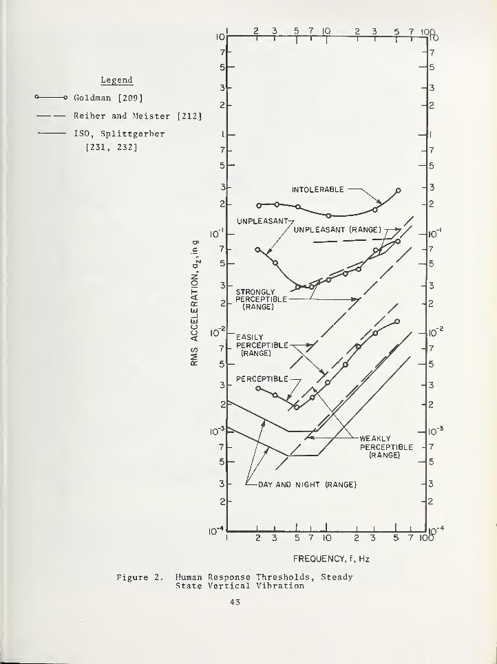
Legend
Goldman [209]
Reiher and Meister [212]
ISO, Splittgerber
[231, 232]
C7>
C
tMo
<a:UJ_jLlIoo<CO
10
7
5
3
2
I
7
5
10"
5 7 10
T"5 7 IOCT
7
- 5
UNPLEASANT^ /UNPLEASANT (RANGE) 7—5^
/-DAY AND NIGHT (RANGE)
WEAKLYPERCEPTIBLE
(RANGE)
J L2 3 5 7 10 2 3 5 7 I0(
Figure 2.
FREQUENCY, f, Hz
Human Response Thresholds, Steady-State Vertical Vibration
43

I
Legend
Lenzen [127]
ISO, Splittgerber
[231, 232]
C7>
<1x1
_JIxl
OO<
cc
10
7 -
5 —
10
2 3 5 7 10 2 3 5 V 100101—
r
- 7
5
-SHORT-TIME, INTERRUPTEDNIGHT (RANGE)
J L I I J L
5 7 10 2 3
FREQUENCY, f, Hz
3
2
10-
5 7 100
Figure 3, Human Response Thresholds,Transient Vertical Vibration
44

allowable is an order of magnitude (1 x 10) below the ISO Guide - Splittgerberallowable for a similar perception range. Except for f < 4 Hz , the ISOGuide-Splittgerber interrupted day and short-time, interrupted night-fall approximately an order of magnitude below the Lenzen slightly perceptiblerange. No definite conclusion can be drawn except that, relatively speaking,either Lenzen 's allowables are too high for slightly perceptible boundariesor the Splittgerber allowables are too restrictive for the interruptedday and short -time, interrupted night boundaries.
Horizontal vibrations are considered with respect to wind loadingon high-rise structures. The vibration direction induced in the humanis generally considered as side-to-side or back-to-chest for a standingor sitting human. The horizontal vibrations are considered transientfor these comparisons however, each author's definition of the natureof transient vibration is different. Transient vibration infers thatthe structure is responding to either gust loading or the short time (suchas the Splittgerber designation) lateral vibration as it oscillates fromthe excitation of the rise and fall of the peak of a storm activity. Alldata are compared on a basis of frequency and rms acceleration. Inheredata were in the form of peak acceleration or deflection, transformationswere made consistent with equations (1) and (2).
Blume [200] compiled data from others and their own experiments.They determined a median for a perception threshold for horizontal vibration.Blume's tests exposed the subjects to an oscillatory motion of which thetotal duration was not designated, however, it was observed that the subjectsresponded to the initial acceleration peak. This threshold is shown onfigure 4 with boundaries of +^ s , the unbiased estimation of the standarddeviation. The data compilation covers a large frequency range of .2< f < 30 Hz. Most high-rise structures fall in the lower portion of theband of f <^ 1 Hz. For this lower region of the data, the threshold ofperception is approximately constant with respect to frequency. The medianthreshold is between 0.0015 and 0.002 g (rms) and the estimated standarddeviation is approximately 0.001 g (rms).
Splittgerber [232] recommends adjustments to the ISO Guide for horizontalvibrations similar in manner to the way in which they were applied tovertical vibrations. Horizontal vibrations or accelerations, a , referto back-to-chest and right-to-left side orientation with respec^'^o vibrationinput to the human. These levels of allowable vibration are shown infigure 4 for short-time day and interrupted day for private homes situatedin a district with prevailing residential buildings. The short-time daywould be applicable to gust loading response, whereas the interruptedday would be applicable to response from the rise and fall of the peakof a storm activity. The ISO Guide-Splittgerber alloA^?able vibrationsare not applicable for f < 1 Hz . The trends of the ISO and Blume dataappear consistent and the bounds are similar and coincident for some ofthe band width of allowables. The ISO Guide-Splittgerber short-time dayallowable is approximately one order of magnitude higher than the Blumedata and the ISO Guide-Splittgerber interrupted day allowable. The ISOGuide-Splittgerber allowables indicated that humans are less sensitiveto short time vibrations than the longer exposure period of an interruptedvibration
.
Chen and Robertson [203] presented low frequency threshold humanresponse data for horizontal vibrations for .067 < f < 0.2 Hz. The meanof the perception threshold (50th percentile threshold) is shoAm on figure4 with boundaries of plus and minus the unbiased estimated standard deviation.The Chen and Robertson data is offset on the acceleration axis by a factorof approximately 2 with respect to the Blume data and the Chen and Robertsondata are higher. The trend of their data is divergent from the trendof the Blume data, this is, for decreasing frequency, the perception thresholdis decreasing for the Blume data and increasing for the Chen and Robertson
45

Legend
— ISO Splittgerber
[231, 232]
— Blume [200]
— Chen and Robertson
[203]
© Reed [227]
FREQUENCY, f , Hz
Figure 4. Human Response Thresholds,Transient Horizontal Vibration
46

data. The two sets of data do not overlap but are adjoining, therefore,it is impossible to determine any transitional trends for the connectingfrequency ranges. The Chen and Robertson data indicate an estimatedstandard deviation of approximately 0.001 g which is similar to the estimatedstandard deviation of the Blume data.
Reed [227] presented an approach to human perception that was differentfrom all other literature reviewed. Perception levels were determinedfrom structures in service. Two discrete points were determined fromthese high-rise structures subjected to strong storms. Several differentsubjective evaluations resulting in various terms referring to motionperception were made. A nuisance -comfort evaluation was made throughpersonal interviews. It was found for the two structures that 37.6 percentof the people felt that the motion was a nuisance and/or uncomfortablefor the lower level acceleration, 0.002 g, (figure 4) and 60.5 percentfelt the motion to be a nuisance and/or uncomfortable for the higher levelacceleration, 0.005 g (figure 4). It should be noted that one pointof the Reed data falls on the median of the perception threshold of Robertsondata and the other point of the Reed data falls close to the median ofthe perception threshold of the Blume data. However, Reed's discretepoints do not agree with the Chen and Robertson and Blume data in thatthe latter two are perception thresholds whereas the Reed data is anuncomfortable region. Subjective classifications are difficult to conclusivelycompare, however, these do appear to be inconsistent.
The data for the low frequencies, f < 1 Hz, for the horizontal vibrationis insufficient to determine whether it Ts inconsistent or that thereis a change of trend of acceleration response. In a gross sense, thedata could indicate an increase in perception level as frequency decreases,a similar trend as that indicated for the transient and steady state verticalvibrations at the lower frequencies (figures 2 and 3). Much informationneeds to be obtained for perception thresholds of horizontal vibrationsfor f < 1 p{z . This frequency region will be difficult to interpret dueto the predominance of kinetosis (motion sickness) which both the ISOGuide [231] and Reed [227] have observed.
Chang [221] presented data and specifications for human responseto horizontal vibrations; however, these data are not used here forcomparisons as their basis is questionable. Chang's acceleration sensitivitylevels were determined from tests performed by Parks and Snyder [211]for 1 < f < 27 Hz for subjects strapped to a seat and subjected to verticalvibrations. Transformation of this narrow band vertical vibration datato broadband horizontal vibration specifications is questionable. Reed[227] also points out that a review and re- interpretation of Parks' andSnyder's report resulted in a large change in the threshold values atf = 1 Hz for vertical vibrations. This draws even more question to theChang specification.
An overall comparison is made (figure 5) of perception levels fortransient vertical, transient horizontal and steady state verticalvibrations. Extreme boundaries of similar perception thresholds weredetermined from figures 2, 3 and 4. Each of the three classes of vibrationswith the respective extreme boundaries were then plotted on figure 5.
The boundaries are broad; trend similarly in some areas and are divergentin others. Divergence of extremes occur in all three vibration categoriesfor f < 5 Hz. Divergence is especially evident for the transient verticalvibrations. Acceleration perception levels for transient vertical vibrationsare higher compared to steady state by an order of magnitude. The accelerationlevels generally translate down without a change in frequency (figure5) from transient to steady state thresholds. Generally comparing transientvertical and transient horizontal vibrations, the perception level forhorizontal is approximately one order of magnitude below the vertical.
47

CM
H < ZZ H OiiJ 2 -
Z LiJ (E< Qc mtr O ^H X >
oJ Lto CVJ
I I I
I I I
'Oin ro CVJ o r- If) ro CM
~ O
lO
ro
CM
O
lO
ro
CM
- N Ozin yj
ro
CM
— in
ro
CM
A'xd'Zd '6'NOIiVd31300V SViH
48

There is also a general trend of a shift of the frequency to the leftfor the horizontal with respect to the vertical transient vibrations.That is, there is both a reduction of acceleration as well as frequencyfor a given threshold of perception for transient horizontal vibrationas compared to transient vertical vibration. The "appendage" of transienthorizontal vibration response (figure 5) for f < 0.2 Hz trends similarto the transient vertical vibration response.
The broad band of variance for threshold levels, trends of humanresponse with respect to frequency, and discontinuities and gaps in datademonstrate the need for considerable study in the domain of human responseto structural vibrations. Considerably more questions arise in the areaof human response to transient vibrations than to steady state vibrations.Definition of a transient load in itself is a very complex and difficulttask. These comparisons were not intended to compile all available data,but to present selected data and research representing a broad expanseof time from 1931 to the present.
4 . 5 Discuss ion .
The problem of designing building structures for deflection whichare as economical as the state-of-the-art of construction permits andare satisfactory with respect to serviceability, funtional ity , and aestheticand human requirements is composed of three parts: 1) the definitionof the excitation (forcing function) ; 2) the definition of the structuralcharactertistics and 3) the definition of the deflection or response require-ments. These three are vitally connected and one cannot consider eachindividually without regard to the other two. Each of the three partsof the problem are random variables and a truly satisfactory answer cannotbe obtained without a probabilistic formulation, coupled with cost optimization.Methodologies for such a solution exist, although a realistic practicalsolution is still far off. Some parts of the puzzle are already available:wind loads and gusts have been defined probabilistically, dynamic analysesof complex structures have been performed and some indication of humanresponse to motion is known. Many pieces are still missing: what shouldthe forcing motion be for human activity on a floor system; what is thestatistically quantified human response to damped vibration; what is theactual dynamic character of a building as compared to what can be modeled;what role does the psychology of fear have in the human response to motionof buildings, etc.?
Much needs to be determined about human response to motion in buildings.But more importantly, a definition of the total problem must first beformulated, each missing piece must be identified, and then it must bedecided to what extent it is worthwhile to get a complete answer to eachquestion
.
By examination of the literature in the area of human response, itis clear that previous work is either inapplicable, i.e., it is concernedwith motions well above that acceptable in buildings or incomplete (nopsychological evaluation), inadequate consideration for damping, no clearlydefined test conditions, etc. It is possible to obtain the required answerswith a good deal of effort in a broad research program involving cooperationbetween psychologists, physiologists, engineers, builders and statisticians.Ultimately such a program is necessary to provide an adequate andscientifically based guide for the totally functional building structure.
49

5. References
Static Defl ej^'tj_ons
1. ACT Connittee 435, "Allowable r)e:Plections" , ProceedingsAmerican Concrete Institute, Vol, 65, Paner Mo. 65-31,1068, pp. 433 -44-1 .
2. ACT Conmittee 318, Building Co d e Re g^uirements for ReinforcedConcrete (ACI 31 8 - 717) , American Concrete Institute,Detroit, Michigan, 1971.
3. Allen, D. E., "Serviceability Criteria for Deflectionsand Vibrations", Building Structures Section, Divisionof Building Research, National Research Council of Canada,NBC of Canada, Supplement No. 4, Commentary Mo. 4, 1970,pp. 597-598.
4. Aluminum Construction Manual , Specifications for AluminumStructures , The Aluminum Ass~ociation , Mew York City,Nov. 196 7.
5. Blakey, F. A., "Deflection as Design Criterion in ConcreteBuildings", Transactions of the Civil Engineering
,
Institution of Engineers, Australia, Vol. C. E. 5, No. 2,Sept. 1963, pp. 55-60.
6. Buchert , K. P., Mulner, W. , and Ruhey, H.,"Application
of Turn-Key Construction to Industrialized Urban Housingin Missouri - Summary Report", Mizzou Housing Project .
7. Davenport, A. C, "Tlie Treatment of V'ind Loading on TallBuildings", Proceedings of Symposium, Univ. of Southampton,April 1966.
I t t
8. Deformations,Report No. 4, Comite Europeen du Beton,
"5th Session, Vienna, April, 1959 .
9. Jenkins, R. A. S., Plowman, J. M. , and Haseltine, B. A.,"Investigation Into the Causes of the Deflexion of HeatedConcrete Floors Including Shrinkage", Structural Engineer
,
Vol, 43, No. 4, April, 1965, pp. 105-116.
10. Joint WRC - ASCE Committee on Plasticity Related to Design,"Commentary on Plastic Design in Steel: Deflections,"Progress Report No . 7
,Proceedings ASCE, Vol. 86, No. EM 2,
Paper 2454,Apr. , 1960
, pp. 141-160.
11. Manual of Steel Construction , American Institute of SteelConstruction, Seventh Edition, New York, 1970, pp 5-35,5-36.
12. Marino, F. J., "Ponding of Two-Way Roof Systems", EngineeringJournal , American Institute of Steel Construction, Vol. 3,No. 3, July 1966, pp. 93-100.
13. Onysko, D. M. , "Performance of Wood-Joist Floor Systems",Forest Products Laboratory Information Report np-X-24
,
Canadian Forestry Service, Department of Fisheries andForestry, January, 1970, Ottawa,
50

14. Report of Structural Use of Aluminuin , The Institution ofStructural Engineers , London ,
Jan., 1962.
15. Skempton, A. W., and MacDonald, D. H. , "The Allowable Settlementof Buildings", Proceedings , Institution of Civil EngineersLondon, Vol. 5, Part 3, Paper No. 50, Dec, 1956, pp. 727-762.
16. Standard Specifications and Load Tables , "Open I'/eb SteelJoists and Longspan Steel Joists"'^'"^ Steel Joist Institute,Arlington, Virginia, 1970 Edition.
17. Stevens, L. K. , "Direct Design by Limiting Deformations",Proceedings , Institution of Civil Engineers, Vol. 16, July,1960, pp. 13 5-258.
18. Thomas, F. G., "Strength of Brick Work", S tructural Engineer,
Vol. 31, No. 2, Feb., 1953, pp. 35-46, No. 7, July, I960,pp. 187-189.
19. Timber Construction Manual , American Institute of TimberConstruction, Washington, D. C, First Edition, John Wileyand Sons, Inc., New York, 1966.
20. Vermeyden, P., "Strength and Stiffness of Wood Joists",Heron, Vol. 9, No. 2, 1961.
21. Whittemore, H. L., Cotter, J. B., Stang, A. II. and Phelan, V. B.
"Strength of Houses", Application of Engineering Principles toStructural Design, U. S. Dept. of Commerce, National Bureauof Standards, Building Materials and Structures Report BMS 109,April 1948.
22. Wiss, J. F. and Curth, 0. E., "Wind Deflections of TallConcrete Frame Buildings", Proc. ASCE Vol. 96, No. ST7,July, 1970.
Dynamic Deflections
Current Design Practice
23. ACI Committee 318 "Building Code Requirements for ReinforcedConcrete", (ACI - 31 8 - 19 71 )
,
' Detroit , Mich.
24 . American National Standard "Building Code Requirements forMinimum Design Loads Tn Buildings and Other Structures ",
A 58.1 - 1972, American National Standards Institute,New York, N. Y.
25. Beles, A. A. and Ifrim, M. D., "Elements of EarthquakeEngineering" (Elemente de Seismologie Inginereasca) Bucharest,Editura Technica, 1962, 247 pages.
26. Ferry-Borges , J. and Ravara,A., "Earthquake Engineering -
Seismic Design of Reinforced Concrete Buildings", LaboratorioNacional de Engenharia Civil, Lisbon, 1969.
27. Korchinskiy, I. L. "Method of Designing Buildings for SeismicForces", Earthquake Engineering Research Institute
, 1960,pp. 10-15.
28. National Building Code of Canada , National Research Council ofCanada, Ottawa 19T0~.
51

29 . Specification for the Design, Fabrication and Erection ofStructural Steel for Buildings , American Institute of SteelConstruction, New York, February 1969.
30. Steffens , R. J., "Some Aspects of Structural Vibration",Vibration in Civil Engineering , Proceedings of a SymposiumOrganized by the British National Section of the InternationalSociety for Earthquake Engineering, Editor, B. 0. Skip,Butterworths , London 1966.
31. Ward, H. S., "Dynamic Characteristics of a Multistory ConcreteBuilding", Proc. Inst. Civil Engrs . Vol. 43, Aug. 1969,pp. 553-572.
32. Wiegel, R. L. (Editor) "Earthquake Engineering", Prentice Hall,Englewood Cliffs, N. J., 1970.
33. Wiggins, Jr., J. H. and Moran, D. F., "Earthquake Safety inthe City of Long Beach Based on the Concept of Balanced Risk",J. H. Wiggins and Company, September 1971.
Forcing Functions - Wind
34. Ferry-Borges , J. "Dynamic Loads (in Particular Wind andEarthquake Loads)", Preliminary Publication
,Eighth Congress,
International Association For Bridge and Structural Engineering,New York, 1968, pp. 663-686.
35. Davenport A. G. "Wind Loading on Tall Buildings", Proceedings ofDesign Symposium, Northwestern University, Illinois 1970,pp. 109-123.
36. Scruton, C. and Flint, A. R. , "Wind-Excited Oscillations ofStructures", Proceedings , Institution of Civil Engineers,Vol. 27, Apr. 1964, pp. 673-702.
37. Scruton, C. "A Brief Review of Wind Effects on Buildings andStructures", Journal of The Royal Aeronaut ical Society
,
London,May 1966
.
38. Wind Effects on Buildings and Structures, Proceedings of aSymposium held at the National Physical Laboratory, June 1963,Her ^tajesty's Stationery Office, London, 1965.
39. Wind Loads on Buildings and Structures, Proceed i ngs of aTechnical Meeting, Building Science Series 30, NationalBureau of Standards, U. S. Department of Commerce, Washington,D. C. , November 1970
.
Forc ing Functions - Seism ic
40. Parmelee, R. A., Perelman, D. S., Lee, S. L., and Keer, L. M.
,
"Seismic Response of Structure -Foundation Systems", Journal ofthe Engineering Mechani cs D ivis ion ,
ASCE, Vol. 94, No7 EM6
,
Dec. 1968,pp. " 1295-1315.
41. Sarrazin, M. A., Roesset, J.M., and V'hitman, R. V., "DynamicSoil-Structure Interaction, Journa l of the S tructural Division
,
ASCE Vol. 98. No. ST7,July 1972.
^'^• Ui"ti form Building Cod e, International Conference of Building
Officials, Los Angefes , 19 70
.
52

43. V/iegel, R. L. (Hditor) "Earthquake Engineerinr;" , Prentice Hall,Engiewood Cliffs, N. J. 1970.
^ ° cijig Functions - Sonic Room
44. Hubbard, H. II. ^'Nature of the Sonic Boom Problem", Journalof the Acoustical Society of America, Vol. 3^ , Mo. S,
Part 2, 1966, pp. S-1-59.
45. Loivery, R. L. and Andrev/s , D. K. , "Acoustical and VibrationalStudies Relating to an Occurrence of Sonic Boom InducedDamage to a IVindow Class in a Store Front", Contract NAS1 -5813 Andrews Associates, Inc., Oklahoma City, 1966, p. 37.
46. ''ayes, W. H. and Edge, Jr. P. M. , "Effects of Sonic Boom andOther Shock Waves on Buildings", Materials Research andStandards , Vol. 4, No. 11, Nov. 1^F47 pp . 588-593.
47. McKinley, R. 1/. "Response of Glass in V/indows to Sonic Booms",Materi als Research and Standards , Vol. 4, No. 11, Nov. 1964,pp". T94-6no
.
48. Newberry, C. W. "Response of Buildings to Sonic Boom",Journal of Sound and Vibration , Vol. 6, No. 3, Nov. 196 7,
pp . 406-418
.
49. U'iggins, J. II., Effects of Sonic Boom, J. II. Wiggins Co.,Paios Verdes Estates, Calif., July 1969.
Forcing Functions - Shock I'/ave
50. Blasting Up in Builtup Areas, Journal of South African Miningand Engineering, Vol.' 72, No. 3579, Sept. 8, 1961, pp. 569-573.
51. Crandell, F. J. "Cround Vibration due to Blasting and itsEffect on Structures", Journal of the Boston Soc. of CivilEngineers 36, 1949, pp. 222/245.
52. Edwards, A. T. and Northwood, T. D., "Experimental Studies ofBlasting on Structures", Engineer , Vol. 210, No. 5462, Sept.30, 1960, pp. 539-546.
53. Langefors, U., Westerberg, H. , and Kilhstron, B., "CroundVibrations in Blasting" , Water Power , Vol. 10, No. 9, 10and 11, 195 5.
54. Leet , L. D. "Vibration from Construction Blasting", ExplosiveEngineer , Vol. 38, No. 1 and 2, 1960.
55. Wiss , J. F. "Effect of Blasting Vibrations on Buildings andPeople", Civil Engineering , Vol. 38, No. 7, July 1968,pp. 46-48.
Forcing Functions - ^lachinery
56. Anthony, P. J. "Survey to Determine Likelihood of Damage byIndustrial Vibrations:, Sur . Min . Res. Australia, 1965.
57. Novak, M. "The Vibrations of Massive Foundations on Soil",International Association for Bridge and Structural Engineering,Zurich, Vol. 20 , 1960
, pp. 263-28l'.
53

Forcing Functions - Traffic
58. "Measuring Vibration in Building Constructed over Railway-
Line", Civil Fngineering (I^ondon) , Vol. 56, No. 656 , March 1961,
pp. 345'^3T7"."'^
Structural Systems - Houses and Apartmen ts
59. Onysko, D. M. "Performance of I'/ood-Joist Floor Systems;A Literature Review", Information Report nP-X-24, ForestProducts Laboratory, Ottawa, Ontario, January 1970.
Structural Systems - Tall Buildings
60. Chang, F. K. "Wind and Movement in Tall Buildings", CivilEngineering ,
ASCE, Vol, 7,7, pp. 70- 72,August 1967.
61. Chiu, A. N. L.,Sawyer, D. A. and Crinter, L. E., "Vibrations
of Towers as Related to V/ind Pulses", Journal of StructuralDivision
,ASCE, Vol. 90, Part 2, Oct. 1964 ,' pp. 137-158.
62. Davenport, A. G. "The Design of Multistory Buildings AgainstWind", Final Report
,Eighth Congress, International Association
for BriSFe and Structural Engineering, Mew York 1968,pp. 687-692.
63. Davenport, A. C, "The Treatment of Wind Loading on TallBuildings", Proceedings of a Symposium held at the Universityof Southampton , Apr fl 1966
,Pergamon Press, New York 1967.
64. Goldberg, J. E. and ITerness , E. D., "Vibration of MultistoryBuildings Considering Floor and IVall Deformations", Bulletin,Seismological Society of America, Vol. 55, No. 1, Feb. 1965,pp. 181-200.
65. Izhizaki, 1^. and Katsura, J. "On the Vibration of a CylindricalTower Structure Induced by Strong V/inds", Bulletin of theDisaster Prevention Research Institute, Kyoto University,Japan, Vol. 19, Part 2, No. 155, Nov. 1969, pp. 19-23.
66. Korchinsky, I. L. "Vibration of Tall Buildings", EarthquakeEngineering Research Institute, 1960, pp. 56-72.
67. Robertson, L. E, "On Tall Buildings", Proceedings of aSymposium held at tlie University of Southampton, April 1966
,
Pergamon Press, New York 1967.
68. Taj imi , H.,Ichino, I. and Cotoh, H. , "Aseismic Design of
Reactor Enclosure of the Japan Power Demonstration Reactor(JPDR) and its Actual Behavior for Earthquake", Bulletinof the JSME, Vol. 9, No. 34, May 1966, pp. 294-299.
69. Wright, R. N. and Walker, W. H. , Vibration and Deflection ofSteel Bridges, Engineering Journal, American Iron and SteelInstitute N. Y., N. Y., Vol. 9 No. 1, January 1972.
Structural Systems - Foundations
70. Hsieh, Tso Kung "Foundation Vibrations", Proceedings,
Institution of Civil Engineers, Vol. 22, June 1962^"pp. 211-226.
54

71. Richart, F, E., Jr., Hall, J. R. Jr., and Woods, R. n.,"Vibrations in Soils and Foundations", Prentice-Hall Inc.,Englewood Cliffs, New Jersey, 1970.
72. V/hitman, R. V. "Analysis of Foundation Vibrations", Proceedinc^sof a Symposium on Vibration in Civil Engineering, InternationalAssociation of Earthquake Engineering, London 1965, Edited byB. 0. Skip, Butterworths , London 1966.
Natural Frequency
73. Blume, J. A. "Dynamic Characteristics of Multistory Buildings",Jour. Str. niv. Proc. ASCE , Vol. 94, ST2
, pp. 377-402,Feb. 1968.
74. Crawford, R. and Ward, H. S. "Determination of Natural Periodsof Buildings", Bulletin, Seismological Society of America ,
Vol. 54, No. 6," Part A, Pec. 1964, pp. 1743-1756.
75. Hudson, D. E., Keightley, W. n. and Nielsen, N. N. "NewMethod for Measurement of Natural Periods of Buildings",Bullet in, Seismological Society of America , Vol. 54, No. 1
Feb. 1964, pp. 2 33-241.
76. Jacobsen, L. S. "Natural ^^eriods of Uniform Cantilever Beams"American Society of Civil Engineers, Vol. 64, No. ST3,March 1968, pp. 431-460.
77. Janney, J, R. and Wiss , J. F. "Load Deflection and VibrationCharacteristics of Multistory Precast Concrete Building",Journal of the American Concrete Institute , Vol. 32, No. 10,April~1961, pp . n"23-1335T
78. Keintzel, E. "Die Berechnung der Schwingunger vonVielgeschossbauten mit Hilfe Kontinuierlicher Ersatzstrukturen"
,
Bautechnik , Vol. 44, No. 12, Dec, 1967, pp. 420-427.
79. Masur , E. F. "On the Fundamental Frequencies of Vibration ofRigid Frames", Proceedings , First Midwestern Conference onSolid Mechanics, UrFanaV Illinois
,April 1953.
80. Ohsaki, Y. "The Use of Jet Reaction for Dynamic Tests ofBui Idings " , Transactions of the Architectura l Institute ofJapan , No . 1 T2' ,~D e c. 196 7", pp . 9-14
81. Rea, D. , Bouwkamn , J. n., and Clough, R. V.'. "Dynamic Dronertiesof McKinley School Buildings", Department of Ceneral Services,Of-Fice of Architecture and Construction, California,Earthquake Engineering Research Center, University o^California, Berkeley, Nov. 1968, 142 pages.
82. Rubinstein, M. F., and 'hirty, W. C, "Effect of JointRotation on Dynamics of Structures", Proc. ASCE, Vol, 37,No. EM6, pp. 135-137, December 1061.
83. Rubinstein, M. F. "Effect of Axial Deformation on the Periodsof a Tall Building'', Bulletin, Seismological Society ofAmerica , Vol. 54, No."T, Feb. 1964
, pp . 2TrT5"l
.
84. Wiss, J. F. and Curth , 0. E., "Wind Deflections of TallConcrete Frame Buildings", Journal of Structural Division
,
ASCE, Vol 96, No. ST7,July 1970
, pp. 1461-148Tr:
55

Damping
85. I-nglekirk , R. E. and Hatthiesen, R. B., "Forced Vibrationof an Eight Story Reinforced Concrete Building", Bulletinof the Seismological Society of Ameri ca, Vol. 57, No, 3,
June T95T7 pp. 421-436.
86. Jennings, P. C. and Kuroiwa, J. H. , "Vibration and Soil-Structure Interaction Tests of a Nine Story ReinforcedConcrete Building", Bulletin of the Seismological Societyof America , Vol .
^ 58 ,"W. 3, June 196T7pp. 891-916.
87. Lazan, B. J., "Effect of Damping Constants and StressDistribution on Resonance Response of Members", AmericanSociety of ^lechanical Engineers, Paper No. 52-A-8, Nov. 30,Dec. 5, 1952, 9 pages.
88. Nielson, N. N. , "Vibration Tests of a Nine-Story Steel FrameBuilding", Journal of the Engineering >Iechanics Divis ion ,
ASCE, Vol. 92, No. F,M1 , Feb. lJ66, pp. ST^ff:
89. Reed, J. W. , "Wind Induced Motion and Human Discomfort inTall Buildings", Structures Publication No. 310, Dept. ofCivil Engineering, H.I.T., Nov., 1971, Cambridge, Mass.
Damage to Structures - Risk
90. Anthony, P. J., "Survey to Determine Likelihood of Damage byIndustrial Vibrations", Bureau of >lineral Resources, Geologyand Geophysics, Australia 1965.
91. Assessment of Vibration Intensity and its Application toStudy of Building Vibrations, Special Report No. 19,National Building Studies 1952.
92. Geiger, J. "Uber die Beurteilung der Gefaehrlichkeit vonErschuetterungen bei bauten", - Bauingenieur , Vol 34, No. 1.,Jan. 1959, pp\ 19-23.
93. Koch, H. W. "Determining the Effects of Vibration in Buildings"V.D.I.Z. Vol. 95, No. 21, pp. 744-7.
Damage to Structures - Assessment
94. Duvall, W. I. and Fogelson, D. E. "Review of Criteria forEstimating Damage to Residences from Blasting Vibrations",Report Investigations 5968, U. S. Bureau of Mines, 1962.
95. Hudson, D. E. (Editor) "Strong Motion Instrumental Data onthe San Fernando Earthquake of February 9, 1971", EarthquakeEngineering Research Laboratory, California Institute ofTechnology, September 1971.
Vibration Isolation
96. Crede, C. E. "Vibration and Shock Isolation", John Wiley andSons, Inc., New York 1951.
56

97. Den Hartog, J. P., Newland, D. E. and Flory, J. F. "FeasibilityStudy of Shock Isolating a Very Large Structure", ContractAF 29 601 6002 ,
Proj. 8811,University of New Mexico,
Albuquerque, Sept. 1964
.
98. Eberhart, L. L. "Specification of Products for VibrationControl", Journal of Sound and Vibration , Vol. 1, No. 5,
May 1967, pp. 8-1.3.
99. Eberhart, L. L. "Vibration and Structure -borne Noise Control",Journal of the American Society of Heating, Refrigeratingand Air Conditioning, Vol. 8, No. 5, ^lay 1966
, pp. 54-60.
100. Nelson, F. C. "The Use of Viscoelastic Material to DampVibration in Buildings and Large Structures", EngineeringJournal of American Institute of Steel Construction, A/ol. 5,No. 2, Apr. 1968, p. 72.
101. Waller, R. A. "The Design of Tall Structures with ParticularReference to Vibration", Proceedings , Institute of CivilEngineers, Vol. 48, Feb. 1971
, pp . 303-323.
102. Waller, R. A. "Flats Isolated from Vibration", RubberDevelopments , Vol. 19, No. 3, 1966, pp. 91-93.
Floor Vibrations
Analytical Studies on Floor Systems
103. Achenbach, J. D., Zerlic, T. R. , "Flexural Vibrations ofLaminated Plate", Journal of the Eng ineering ?lechanicsDivision
,ASCE, EM3 , June 1971.
104. Ashton, J. E. "Natural Modes of Vibration of Tapered Plates",Journal of the Structural Division
,ASCE, ST4, April 1969.
105. Bleich, H. H. "Frequency Analysis of Beam and Girder Floors"ASCE Transactions , Vol.' 115, 1950,
106. Burkhardt, L. R. "Vibration Analysis for Structural FloorSystems", Journal of the Structural Division
,ASCE, ST7
,
Oct. 1961.
107. Chang, C. C. "Transient and Periodic Response of a LoadedSandwich Panel", J. Aero Sci . , Vol. 28, 1961.
108. Cheung, Y. K.,Cheung, M. S. "Flexural Vibrations of
Rectangular and Other Polygonal Plates", Journal of theEngineering Mechanics Division
,ASCE, EM2
,April, 1971.
109. Janich, R. "The Approximate Calculation of Natural Frequenciesof Rectangular Slal5S Under Various Boundary Conditions",Bautechnik, Vol. 39, 1952.
110. Kirk, C. L. "Vibration of Centrally Stiffened RectangularPlate" J . Royal Aeronaut. Soc , Vol. 65, 1961.
111. Koerner, D. R.,Snell, R. R. "Vibration of Cantilevered Right
Triangular Plates", Journal of the S tructural Division , ASCE.ST5, May, 1967.
57

112. Kurata, M.,Okamura, H, "Natural Vibrations of Partially
Clamped Plates", Journal of the En^^ineering Mechanics Division ,
ASCE, EM3, June IWEJT
113. Lenzen, K. H.,Dorsett, L. P., Sokolowski , M. , "The Vibration
of the Vibrational Characteristics of Steel Joist -ConcreteSlab Floor Systems with Changes in the Structural Parameters",Engineering Archives of the Polish Academy of Sciences . Vol.
114. Lynn, P. P., Kumbasar, N. , "Free Transverse Vibrations of FlatSlabs", Journal of the Engineering Mechanics Division
,ASCE,
E^fl, Feb, r969.
115. Mackey, S., Ying, K. T. "Dynamic Analysis of Floor Systems"Publications of the IABSE ,"Vol. 29-1, 1969.
116. Mindlin, R. D, "Influence of Rotatory Inertia and Shear onFlexural Motions of Isotropic Elastic Plates", Journalof Applied Mechanics, Vol, 18, 1951.
117. Mindlin, R. D. "V/aves and Vibrations in Isotropic ElasticPlates", Proc . of 1st Symposium of Naval Struct. Mech.,Pergamon Press, 1959.
118. Ohmart , R. D. "An Approximate Method for the Response ofStiffened Plates to Aperiodic Excitation", Studies inEngineering ' Mechanics No. 30 ,
Apr. 1968, Univ. of Kansas,TTaivrence , Kansas.
119. Roberts, S. B. "Buckling and Vibration of Polygonal andRhombic Plates", Journal of the Eng. Mec h. Div".
,ASCE, EM2
,
Apr. 1971.
120. Rogers, C. L. "Floor Systems", Chap. 10 in "Dynamics of FramedStructures", John Wiley f. Sons, ^1. Y., 1959 .
121. Sinitsyn, A. P. "Tables for the Calculation of the Frequenciesof Plates and Beams", Soviet Abstracts of Mechanics (EnglishTransl.) No. 2, Ref. 2384.
122. Ungar , E. E. "Free Oscillations of Edge -Connected SimplySupported Plate Systems", Tran sacti ons of ASME , Vol. 83,(BV4), 1961.
123. Wiley, J. A. "A Study of the Vibration of Plates by theRitz Method", Studies in Engineering Mechanics No. 5 ,
May1960, The Univ. of Kansas
,Lawrence, Kansas.
124. Yu, Y. "Flexural Vibrations of Elastic Sandwich Plates",J. Aero. Sci . Vol. 27, 1960.
Experiments on Steel Joist Floor System s (Lenzen )
125. Barr , C. V/., "Vibration Damping of Anisotropic Plates",Studies in Engineering ^-echanics No. 9 , Center for Research
.in~TIhginee"ring Science, TfrTiv. of Kansas
,Lawrence, Kansas,
June 1961
.
58

126. Keller, J. E. , "namnin'z Considerations in Vibration Response off'umans", Stud ies in F-n.^ineer i nfy ^Jechanics No. 4 , Center forResearch m TThgmeerinc^ , UnTv. of Kansas
,Lawrence, Kansas,
May 1060.
127. Lenzen, K. 1!., Dorsett , L. P., "Effect of the Variation ofStructural Para'^ieters on the Vibrational Characteristics ofSteel Jois t -Concrete Slab Floor Systems and Su,r;f^ested Desif^ns'",
Studies in Enj^. Mech. No. 32 , Auo . 1968 , Univ. of Kansas,Lavrence , Kansas
.
128. Lenzen, K. N.,Murray, T. '!.
, "Vibration of Steel Rean-ConcreteFloor Systems", Studies in En^r . Mech. No. 29
,Apr. 1068
,
Univ. of Kansas, Lawrence, Kansas.
129. Lenzen, K. U., "Vibration of Steel Jois t -Concrete Slab FloorSystems", Studies in Eng. Mech. No. 16 , Dec. 1963, Univ. ofKansas, Lawrence, Kansas.
130. Lenzen, K. H.,Keller, J. E. "Vibration of Steel Joist -Concrete
Slab Floor Systems", Studies in Eng. 'lech. Nos. 1 and 3,Sept. 1959 and May 1960, Univ. of Kansas, Lawrence, Kansas.
131. Lyons, 1/. E., "A Study of Various Damping Devices forControlling Vibrating Floor System.s", Studies in EngineeringMechanics, No. 12 , June 1962, Univ. of Kansas, Lawrence, Kansas.
132. Meyer, L. D., "Vibration of Floor Systems of Steel FramedBuildings", Studies in Engineering Mechanics, No. 26
,
Univ. of Kansas, May 1967 , Lav/rence , Kansas.
Drift
133. "Allowable Deflections", Report by Subcommittee 1, ACTCommittee 435, AC I Journal , Vol. 65, No. 65-31, June, 1968,pp. 433-443.
134. ASCE-IABSE International Conference on Planning and Designof Tall Buildings, Preprints, Volume DS, "Discussion -
Summary", Lehigh Univ. Bethlehem, Penn. August 1972.
135. ASCE-IABSE International Conference on Planning and Designof Tall Buildings Preprints, Reports Vol. 11-17, "DesignMethods Based on Stiffness", Lehigh Univ., Bethlehem, Penn.August 1972.
136. ASCE-IABSE International Conference on Planning and Designof Tall Buildings Preprints, Reports Vol. III-24, "Stiffnessand Crack Control", Lehigh Univ., Bethlehem, Penn., August 1972.
137. "Building Code Requirements for Reinforced Concrete (ACI - 318 - 71)
"
American Concrete Institute, Detroit, ^lichigan, 1971.
138. Dalgliesh, A. and Ward, H. S., Discussion of "WindDeflections of Tall Concrete Frame Buildings", Journal ofthe Structural Division
,ASCE, Vol. 97, No. ST4, April, 1971,
pp. 1370-1374.
139. Davenport, A. G., "The Treatment of IVind Loading on TallBuildings", Tall Buildings
,Proceedings of a Symposium held
at the University of Southampton, April, 1966, pp. 1-44.
59

140. Davenport, A. C, "^lew Approaches to the Design o£ StructuresAfrainst Wind Action", Proceedings of the Canadian StructuralEngineering Conference, Canadian Steel Industries ConstructionCouncil, Feb. 1968.
141. Davenport, A. C, "Wind Loading on Tall Buildings", WindEffects on High-Rise Buildings ,
Proceedings of the DesignSymposium held at Northwestern University, Evanston, 111.,March 1970, pp. 109-123.
142. Davenport, A. G., Hogan, M. , and Vickery, B. J., "An Analysisof Records of Wind Induced Building Movement and ColumnStrain Taken at the John Hancock Center (Chicago)", BLWT- 1 0- 1970
,
Boundary Layer Wind Tunnel Lab., Univ. of Western Ontario,London Canada, Sept. 1970.
143. Driscoll, C. C, "Approximate Design of Unbraced FramesIncluding Deflection Effects", Plastic Design of Multi-StoryFrames, Fritz Engineering Laboratory, Report 273.20, LehighUniversity, Bethlehem, Pa., 1965, Ch .
16'.
144. Fleming, R. , "V/ind Action on Buildings", Engineering , Vol. 145,No. 3765, March 11, 1938, pp. 280-282.
145. Frischnann, W. V/. and Prabhu, S. S., "Planning Concepts UsingShear V/alls", Tall Bu ildings
,Proceedings of a Symposium held
at the UniversTty oT Soutliampton,April, 1966
, pp. 83-100.
146. Hisada, T., "Earthquake Loading and Response Criteria", Planningand Design of Tall Building s, Third Regional ConferenceProceedings, Tokyo, Japan, 5'ept. 1971, pp. 63-70.
147. Khan, F. R. , "The Nature of Uigh-Rise Buildings", InlandArchitect, July, 1967, pp. 6-11.
148. Large, C. E., Carpenter and ?lorris , C. T., "Tests and Designof Steel Wind Bents for Tall Buildings", Ohio State UniversityEngineering Experiment Station , Bulletin No . 93 , Vol . V,Sept . , 193 5 .
149. Mackintosh, C, "Ductility of Building Frames Under EarthquakeLoad", Civil Engineering , Vol. 37, No. 5, May, 1967, pp. 60-62.
150. Novak, M. and Davenport, A. C, "Aeroelastic Instability ofPrisms in Turbulent Flow", Jour, of Engrg. Mech . ASCE , Vol. 96,EM 1, 19 70.
151. Novak, M., "Galloping Oscillation of Prismatic Structures",
Jour, of Engrg. Mech . ,ASCE, Feb., 1972.
152. Parmelee, R. A., "The Nature of Wind and High-Rise Buildings:Chicago Style", V/ind Effects on High-Rise Buildings
,
Proceedings of the Design Symposium held at NorthwesternUniversity, Evanston, 111., March 1970, pp. 1-11.
153. Philcox, K. T. , "Some Recent Developments in the Design ofHigh Buildings in Hong Kong", Th e Structural Engineer''^Vol. 40, No. 10, Oct., 1962, pp. 303-323.
''
154. Rathburn, J. C, "Wind Forces on a Tall Building", TransactionsASCE, Vol. 105, 1940, pp. 1-41. '
60

155. Reed, J. W. , "V/ind Induced Motion and Human Discomfort inTall Buildings", Structures Publication No. 310, Dept. ofCivil Engineering, M.I.T., Cambridge, Mass., Nov., 1971.
156. "Response of Buildings to Lateral Forces", ACI Committee 442,ACT Journal , Vol. 68, No. 2, Feb., 1971, pp. 81-106.
157. Robertson, L. F,., "On the Design of Tall Buildings Subjectedto the Turbulent V/inds", Wind Effec ts on Migh-Rise BuildingsProceedings of the Design Sympos lum^'eld aF NorthwesternUniversity, Evanston, Til., March, 1970, pp. 175-187.
158. Spurr, H. V., "Wind Bracing", McGraw-Hill, 1930.
159. Steel Designers' Manual, British Iron and Steel Federation,Frederick Ungar Publishing Co., New York, 1970.
160. Uniform Building Code, International Conference of the BuildingOfficials, Los Angeles, 1970 Edition.
161. Vickery, B. J., "On Reliability of Oust Loading Factors",Technical Meeting Concerning Wind Loads on Buildings andStructures, National Bureau of Standards, Washington, D. C,1966.
162. Vickery, B. J. and Clark, A. V/., "Lift or Across-Wind Responseof Tapered Stacks", preprint 1385, ASCE Nat. Struct. Engrg.Mtg., Baltimore, Md
. ,April, 1971.
163. Williams, E. L. and Badland, P. A., "The Effects of LateralLoads on Steel Framed Buildings", Journal of the Institutionof Civil Engineers, London, Vol. 31, 1948, pp. 117-155.
164. Wiss, J. F. and Curth, 0. E., "Wind Deflections of Tall ConcreteFrame Buildings", Proceedings ASCE, Vol. 96, No. ST6, July,1970. pp. 1461-148(1.
165. Wooten, L. R. and Scruton, C.,"Aerodynamic Stability", paper
No. 5, Proc . Seminar on the Modern Design of Wind SensitiveStructures, CIRIA, ICE, London, England, 1970.
Human Perception and Response to Motion
State of the Art Reviews
166. Cope, F. W. , "Problems in I^uman Vibration Engineering",Ergonomics , Vol. 3, No. 1, Jan. 1960.
167. Digby, V! . P., Sankey , H. R. , "Some Preliminary Notes on aStudy as to Human Suscentibility to Vibration", The Electrician ,
Vol, 67, Sept. 15, 1911.
168. Goldman, D. E., von Gicr]:e, H. E., "Effects of Shock andVibration on flan". Shock and Vibration Handbook , C. M. Harrisand C. E. Crede , editors; McGraw-Hill, N. Y., 1961. Vol. 3,Chap. 44.
169. Guignard, J. C, "Human Sensitivity to Vibration", Journalo f Sound and Vibration , Vol. 15, No. 1, 19 71.
170. Hornick, R. J., Lefritz, N. M. , "A Study and Review of HumanResponse to Prolonged Random Vibrations", Journal of theHuman Factors Society , Vol. 8, No. 6, Dec. 1966.
61

171. Jacklin. H. H. , "Human Reactions to Vibration", Journal ofthe Soc. of Automotive Engineers, Vol. 39, No. 4, i)ct7 1936.
172. Koch, H. W. , "Determination of the Effect of StructuralVibrations", Zeitschrift des Vereins Deutocoher Ingenieure
,
Vol 95, No. 21, July 1953.
173. Lippert ,S., "Human Response to Vertical Vibrations", Journal
of the Soc. of Automotive Engineers , Vol. 55, May 1947.
174. Mallock, H. R. A., "Vibrations Produced by Working of Trafficon the Central London Railway", Board of Trade Report , CommandPapers, No. 951, 1902.
175. Onysko, D. M. , "Performance of Wood-Joist Floor Systems - ALiterature Review", Forest Products Laboratory, InformationReport OP-X-24, Jan. 1970, Ottawa, Ontario, Canada.
176. Postlethwaite , F., "Human Susceptibility to Vibration",Engineering , Vol. 157, Jan. 28, 1944.
177. Richards, J. E., "Summary of Existing Information on theHuman Reaction to Vibration", Report^No. 28 (B.B. 319),British Shin -bui Idings Research Assoc., 1949.
178. Steffens , R. J., "Some Aspects of Structural Vibration",Vib ration in Civil Engineering ,
Proceedings of a SymposiumOrganized by the British ^Jational Section of the Int. Assoc.for Earthquake Engineering, London, April, 1965, pp. 1-30.
179. Woodson, W, E., "Human Engineering Guide for Equipment Designers",Univ. of Calif. Press, 1954.
180. Wright, D. T., Green, R. "Human Sensitivity To Vibration",Report No. 7, Ontario Joint Highway Research Programme,Feb. 19 59.
181. Zeller, W. , "Research on Mechanical Vibration and its Effecton the Human Organism", Bauiup-enieur , Vol. 12, No. 32/33
,
1931.
Physiological Responses
182. Alexander, S. J., et al. ,
"Wesleyan University Studies ofMotion Sickness: III. The Effects of Various AccelerationsUpon Sickness Rates", Journal of Psychology , Vol. 20, 1945.
183. Ashe, V/. F., "Physiological and Pathological Effects of^Techanical Vibration on Animals and Man", NIH Report No. 862-4,Grant No. OH- 6, 1961.
184. Coermann, R. R.,Magid, E. B., Lange , K. 0., "Human Performance
Under Vibrational Stress", Journal of the Human Factors Society,
Vol. 4, No. 5. , Oct. 1962.
185. Coermann, R. R. , "The Effect of Vibration and Noise on theHuman Organisms", Ringbuch der Luftfahrtechnik , Part VF
,
No. 1, 1939, MOS Translation, 1946 and also RTP/TIB, TranslationNo. GDC 10/7686 T.
62

186. Coermann, R. R. ,"Investifrations into the Effect of Vibration
on the Human Body", Uiftfahrtmed izin , Vol. 4, No. 2, 194 0,
Translation, Royal Aircraft RstabliThment ,Farnborouf];h
,
No. 121, 1946.
187. Clark, V. S. Lanp;e , K. 0,, Coermann, R. R. , "Deformation ofthe Human Body Due to Uni -Directional Forced SinusoidalVibration", Journal of the Human Factors Society , Vol. 4,No. S, Oct. 1962
.
188. Dieckmann, D., "\ Study of tlie Influence of Vibration on Man",Frgonomics , \'ol. 1, No'. 4, Auc;. 19 50.
189. Edwards, R. G., Lan^e, 0., "A Mechanical Impedance
Investitration of Human Response to Vibration", Final Renortfor Dec. 1962-Feb. 1^64^ Aeronaut. Research Lab., Hniv. ofKentucky, Oct. 1964.
190. Edv/ards , D. A. W. "The Effects on Human Subjects of Air andStructure - Borne Vibrations of A/'arious Frequencies", RAFFlying Personnel Research Committee Report, Farnborourrli , 1950.
191. Franke, E. K., "The TTechanics of Vibrations in the HumanBody", US D.O.D. Research and Development Laboratory, Code5140, 1955.
192. Franke, E. K., "Response of the Human Skull to MechanicalVibration", Journ al of the Accoustical Soc. of America , Vol.29, No. 6, Nov. 1956.
193. Cuignard , J. C, "Defining Limits of Human Exposure toVibration", Paper to the Technical Meeting on "Environmentaland Hunan Factors in Engineering", Southampton Univ., Apr. 1967.
194. Guignard, J. C, "Physiological Effects of Mechanical Vibration",Proceedings o f th e Royal Society of Medicine , Vol. 53, 1960.
195. Hornick, R. J., "Vibration Isolation in the Human Leg",Journa l of the Human Factors Society , Vol. 4, No. 5., Oct. 1962.
196. Magid, E. B., Coermann, R. R., "The Reaction of the Human Bodyto Extreme Vibrations", Proceeding s , Institute of EnvironmentalScience ,1960.
197. Magid, E. B., Coermann, R. R.,Ziegenruecker , G. if., "Human
Tolerance to V'hole Body Sinusoidal Vibration", Journal of theAerospace Medical Soc.', Vol. 31, No. 11 , 1960.
Subjec tive Responses of Humans
198. Alexander, S. J., et at., "Wesleyan University Studies of>totion Sickness: Prediction of Sickness on a VerticalAccelerator by Means of a ^totion Sickness History Questionnaire",Journal of P sychology , Vol. 2 0, 1945.
199. Bekesy , G. V., "Vibration Sensation and the Sensitivity ofStanding and Sitting Human Beings to Sinusoidal Vibration",Akustische Zeits chrift, Vol. 4,^1939.
200. John A. Blume ^ Associates Research Division, "Motion Perceptionin the Low Frequency Range", San Francisco, 1969, ContractAT(26-l)-99 for HSAEC.
63

201. Bryce, W. D., "A Human Criterion for the Acceptance of TransverseSeat Vibration", Journal of Sound and Vibrati on, Vol, 3, No. 3,
1966.
202. Chaney, R. F, . ,"Subjective Reaction to Whole Body Vibration",
Boeing Co. Report, Wichita, Kansas, Sept. 1964.
203. Chen, P. W.,Robertson, L. E., "Ihiman Perception Thresholds
of Horizontal Motion", ASCF, Structural Div. Journal, Vol. 98,No. ST8, August, 1972.
204. Coldman, D. F,., "Mechanical Vibration and its Effects on Man",Lecture and Review Series No. 52-1. Naval >Iedical ResearchInstitute
,TTetFesda", "cT. , Pel). 195 2.
205. Coldnan, D. E., von Cierke, H. E., "The Effects of Shock andVibration on ^lan", Lecture an d Review Seri es No. 60- 3, NavalMedical Research Ins"titute, Bethesda, "McT. , Jaru 1960".
206. Khan, F. R.,Parmelee, R. A., "Service Criteria for Tall
Buildings for IVind Loading", Proceedings of the 3rd Int.C
o
nf. on 1'/ind Effects on Buildin?Ts and Structures , Tokyo,^nt. 1971.
207. ^lagid, E. C, et al . ,"Physiological and Mechanical Response
of Human to Longitudinal Whole Body Vibration as Determinedby Subjective Response", Technical Renort 61-402, Air SystemsDiv. , USAF
,May 1961
.
208. Meister, F. J., "Sensitivity of Human Beings to Vibration",Veroffent lichungen aus dem Institute fur Schall undWa rm e fo tT? clrun g 'T e cFn"". "ochTs clTule
,Stuttgart, Vol. 6. 1935.
209. '^eister, F. J. "Hum.an Sensitivity to Vibration", Forschungauf dem ^ebiete des Ingenieur^^'^esens , Vol. 6, No. 3, "19 35.
210. Parks. D. L., "'^e^ining Human Reaction to Whole-Body Vibration",Journal o f th e Human Factors Society, Vol. 4, !sO . 5, Oct. 1962.
211. Parks, D. L. and Snyder, F. V'., "Human Reaction to Lev;
Frequency Vibrations", Boein'^ Comnany, V'ichita Div., D3-3512-1,July 1961.
212. Reih.er, H., Meister, F. J., "The Sensitivity of Humans toVibrations", Forschung auf dem Gebiete des I ngenieurv/esens
,
Vol. 2, No. ir,'^ov. T9 31. '
~
Observed Human Response
Perfo rmance in a Vibrating Environment
213. Alexander, S. J., et al . ,'"^'^'csleyan L'niversity Studies of
Motion Sickness; The Effects of Sickness Hpon Performance",Journal of Psychology , Vo 1 . 2 0, 1045.
214. Buckhout , R. , "Effect of Whole Body Vibration on Hum.anPerform.ance" , Journal of the Human Factors Society, Vol. 6,No. 2, April l^T^. - - -
215. Dennis, J. P., "The Effect of Whole Body Vibration on aVisual Performance Task", Ergonomics
,Vol, 8, No. 2, Apr. 1965.
64
216. Frazcr, T. M. ,Hoover, C. N., Ashe, W. F., 'Tracking Performance
During Low Frequency Vibration", Aerospace Medicine, Vol. 32,1961/
217. Holland, C. L,, "Performance Effects of Long Term RandomVertical Vibration", Journal of the Human Factors Society
,
Vol. 9, No. 2, Apr. IWT.
218. Hornick, R. J., "Effect of Whole Body Vibration in ThreeDirections Upon Human Performance", Journal of EngineeringPsychology , Vol. 1, No. 3, 1962.
219. Lange , K. 0,, Coermann, R. R. , "Visual Acuity Under Vibration",Journal of the I'uman Factors Society, Vol. 4, No. 5, Oct. 1966.
220 . Simons, A. K., Hornick , R. J., "Effects of the VibrationEnvironment in Mobile Systems on Human Performance",Ergonomics , Vol. 5, No. 1, Jan. 1962.
Response to Building Vibration
221. Chang, F. K. , "Wind and Movement in Tall Buildings", CivilEngineering
,Vol, 37, Aug. 1967.
222. Crandall, F. J., "Will 'ly Blasting Damage Property?", EngineeringNews Record , Vol. 144, May 4, 195 0.
223. Davenport, A. G., "The Treatment of Wind Leading on TallBuildings", Proceedings of a Symposium held at Southampton,April 1966.
224. Hansen, H. , "Deflection Characteristics of Wood Joist Floors",Nat. Res. Council Technical Translation, NRC - TT883, Ottawa,1960.
225. Lenzen, K. H. , "Vibration of Steel Joist -Concrete Slab FloorSystem -Final Report", Studies in Engineering Mechanics No. 16
,
Center for Research in Egnineering Science, The Univ. ofKansas, Lawrence, Kansas, Aug. 1962.
226. Russell, W. A., "Deflection Characteristics of ResidentialV/ood Joist Floor Systems", Housing Res. Paper 30, HHFA,Washington, D. C. , 1954.
227. Reed, J. W. , "Wind Induced Motion and Human Discomfort inTall Buildings", Structures Publication No. 310, CivilEngineering Dept., M.I.T., Nov. 1971.
228. Vermeyden, I. P., "Strength and Stiffness of Wood Joists",Heron, Vol. 9, No. 2, 1961.
Vibration Clauses in Standards
229. Duetsche Normen, Enschutterungen im Bauwesen, Einwirkungen
auf Menschen in Cebauden, DIN'4150, Blatt 2, July 1971.
230. Design and Evaluation of: Operation Breakthrough HousingSystems. U. S. Department of Housing and Urban Development,National Bureau of Standards Report 10 200, September 1970.
65

"Guide for the Evaluation of Human Fxj^osure to Whole-Body-Vibration", Draft International Standard ISO/DTS 26.31,
International Orf^anization for Standar^U zation,May 1972 .
Snlitt fTerl:)er , H. , "Die Pinwirkuns^ von F.rschutterunren aufden Menschen in Hebauden", (The Pffects of Vibrations onPeople in Structures), in German, Zeits chrift TechnischeUb erwachun.q , Bd 10 (1969) No. 9, S TT^?^.
Private correspondence, Dr. H. Splitt<Terber to Dr. P. Crist,July 1972.
66

APPENDIX A
Summary of Vertical Deflection Limitations
in
U. S. Codes and Standards
National Standards
Model Codes
State and Local Codes
67

MAT I ON AL STANnARnS
CD
o i> o IT)
•H •H 4-'
o M r—
J
<D
tx E Od) •i-i 1—
1
o oO I—
1
01 1 CD
o •HCJ •"^
J1
r-* t-H E E*^ r—
J
E nJ *
1^ ri
QIP,
Cj
^ + •Hc_ O 1^ T>u CJ o H o •H O
*-> I—
I
M • r-i O O t—
t
Eo O c:
o O O C ^3 •Ht=: ' '
C- wo •H PI c C o
t/) c <D cC •H ctJ
P. o c •M>^ f—
1
J-I (/) u •H Ur—
i
Jh J-i cti oC- c c 1—
t
"M o I—
I
o c c '-i-i t/) c U~- •H•H O I—
1
a> c <D OjCO a- P= M-J t-H
<—
•
t/) c,
rH n;
O '—
1
COC-
•HE—
'
to
u: M •H•H <D H
P-i •H .—
(
o o O o1—
1
cc \o COI—
(
tnto CO o
r—
1
<—
I
CO •H -ao > +->
ci ua;
E ' rH•H ct <U+J <D C <D
c/: cc o C
c<
<H
4-1
D+->
•H!->
If)
c
<D+-1
<D
UOCo !=;
u 1-1 o•H+-1
rt CO uU <-H
•Hu0)
68

NATIONAL STANDARDS
McS
<D iH/2 M-H
urH 01—
<
o ••->
t/i
OS1/1 I/) iH
Ccr; - oH •H .J^
v< to +J +->
nj •Ht/1 to O +J &tj^ CD •(-( •H
c E 13CJ •H U •H
1—1 (D O t-H 0H ;3 t-H C Uto i-i OJ
u 4; c M to•H n- 0
t:' CD r! 03 C toOJ (/) o a O CC rt
o c I-H O to 0r-l 10 c
t^ C 1/) rH !h •H u(/; CJ (U C rt a; 0 t-l
rt X > tA O > IJ > 0 •HI—1 -M -H t—
1
o o H I-H (D l-J
C-, O 00 u H i-J U C
COE-<n1—
1
2:c O1—! \D o O 0
vC VOU (SI
E -J
C
+->
rC t3o
O </) -3 ca
c .I-H +-> •Hc o u (/) rH cO >—
1 -H H (U •H•H a> +-> o C 0 (U to4-J O T-f E •H f-l
U +-> 13 p a; •H3 to W (=! H •H t/1 r—
1
>JS C <1> Z
C +-> ^ o (1) Wt/1 O 4-J o •H l-> ^-|
< i=;+J \0 M CO to 0
O (L) 0) o 0) <f) C~i •f-i +J(_)•»-»> H (-> U r-( o o t-C
< ^. o •t-J •H •HH >—
1 +-1 CO U 4-> •HO 'H O •H !h •H 1—1
^1 M o u•)-' i/i p; a-. (-1 (/) (=; ^ a) cc/: c o i-H t/) o p. p.-t-' 0
1—1 .H C 1-1 •H g in C CO •H4_) - o 0) 4-1
O C O AS u c M •HD f-
I-H U t-i O S-i u !-i - rt tn !-) W.H 4-) >H OJ •H M >s Id <D to H
" ^ Ifl in <D C .-H OC+J Ccues (D C >-i
e o <u E O -H +J C< u 2; H < U 5c c/: I-! I-H 1—1
69

MODEL COnF.S
bec ^.
<D bo •H <D
c rH 4_)
c •H •H t/1
3 4-> (D Ct)
^1 CJ 1—
1
(/I O ><u P, •H•H fx 1—
(
(Ui-H c 3,C o (/) CO •HE « •H 4) •H(D o +J t/i >-i
W. I—
(
(/I u <U •H o<r. i/l (-1 3 VI M- p.c re <-i-i o J-i If. p.
O o (-> 3 c (/) (h
c 1—
I
(/) i-i •H f-i C I/)
o U-i E- 1—1 OJ •Ho u O •rt •(-> 4-) (/I Ei-i o X) u 1 <D <+J !-i
u c E13 £i ^ t;
(L> <D o « P E cJ o« t-J t-J u o o 3 4) C O iH
> l/l l/l <u 1-1 £ IT, E c I—
1
u o nj 03 <-> UI f—l
o s- 1—! 1—1 in o •H lA 13 OJ CCc c P p. rt > C rt o > +->
r-{ p c C 1—1 •H •H U O o H ort C- H I—
1
c -J H
*^
1—
1
c c o o o o oC 00 o \P1—
1
T-l \-J '
—
'
U-
c
<; < 1
CJC 1—
i
c c o(J t3
o 1 •H 1 ou c CJc a) r-^ o
0) <D a-. E o bpU I-H < CTi
(-> <D f—
I
•H 1—
1
131—
(
o o o 13 C •H (D•H o o 3 13
CJ +J ea oc/: Id •H CJP-; o .-( 13c u C -i-i f-,c •T-t •H (J nJ c;u w u •13 O 13 •H
c •H +-1 1—
)
•d•H i-t (/) ,—
1
•H 3 •< CJ •Hi-H o Ph CJ 3•H cq P33 i-l O c c/:
P5 CS e•H U o r
O -13 •H O J- OH t-i U H 3 M C. c(/) •iH o +J 10 3 VC •H PQ
D o CT) P Uec PC Ln 1—
1
r)
70

.STATH AND LOCAL COnP.S
Oo
•HC/j cE-* o f o
oFt—
t
o +->
• 10 uto
c fH O <+- t' <+j cQ Q Q *—m O H o I-H
M-i o (I It.
o oc; t; o CJo IT, i a' (UI—
1
Cj u u !h
•H aj <L c> *^ ob.: >- 4-1 l-J
C o W.
it/i
•H "f t-j ct 1- s K •M,1^ dl f. t-< o r-H i-H
>H ir, rt C cO V. .-( i-H c I-H
rt 0-
or
U-JP-
tn
o•Hw•H>o
p.
u•H<4-lHU0)
p.to
c occI-H
.-3
MHo
o te/—
\
CSJ
p +-> c.•H vo rHu 0-
.
1-H<L) •H
to T3CJ O i-H E ou ,M tJ> u
c a. I-H
u w i-H OI-H
•5•H < •Hl-)
3 t-H 13 oc U •H U •H
w •H n H MUh *-> (-' U Ko !-i O U •H
r« O <u o otn t) X. c; H crt T3 u 10 c ^:
o o rt o< u < CJ u
71

STATn ANn LOCAL CODES
H(U+JU)
C8iH
Pi
M
p^1
ocx
u
OO
•H'v3
O
co
o
<S) (D
O .-I
O '-r. cj
O 4-1
Sh ^c^ -h0) 4-J
•H e !-.
(/) cti OCD O +->
O o
Ou
(U
o
Er̂i
in <D
oO <D
H cd,
4->
•H ec o
O•p e
O O
CvJ
•H f-i tD
C O -1-1
OC O f-i
P O
•H +J GU cfxi•H p
3 OI/) CS r-(
<U !-> <U
E P, >•H O O4-" U i-H
I X
C (U
O - 4-'
iH <D UU 3
C i-H +->
P, w
U 4->
O r
p. b!.
!=: oO I-H
•ri
4-1
u Cd) oi
<4-: +J
P, CO i-H
ns pP O
U c3
P 4J ^•H 4-) 03
(/I 0)
u oo p-Pi
e Id(D CE CD
P(U
E
•H
crcu
Sh
PO
o0) iH!h
O OE >
O tc, 4J ,-1
> rt OO P CD <JJ
O <D
P,--!P-'4-'
10
P3 aj
I 1-1 10 p +J +J4-1 ni M-O !-( (U
p; •Ti LT)P.+j
<D
01
!h
0)p'
OJ
p
o
cup.w
4-1
PCD
E
>oup.e
72

STATU .vm Lnr\]^ cmns
to
b
o03 •H U
<L> 0)+J t3 uto rt cCtJ o !-. iH pr-H rH O
'
'
St<U
es
bc > •H(=; •H rr-J i-H p•H r-H 03 •H o^-> o E 0) H!-, r-H O o o +-1
O 1—1 o in t—
t
up. •H CJ u 10 i-i
p_ T3 > c3 O Sh
;3 •H .—
(
c o O •I-I
1/1 U rH 1—
1
(U H o I—
1
w.
<u U di O i-i M-l Ct/l X +-1 C O+-> c (U O (/5 U O t; U(/) :3 +J o•H rt !h s- 13o 1/1 >H O c O (U (L
o !-> E 03 <D 4-> Uc i-H c f- ^> V. tA, o
(I •H o o C 03 +->
o iH u o >-. 1—
1
t—
1
1/1
o •H rt (=; o P- p. 03
1—1 <D O o 1—
1
p. i-H
p- U u O P,
00 O
ct—
I
HUP!
COP
305
E
o<4-^
C to
o•HW•H>o
p.
P,
Same
octH
in
o
3 I-H
rH Pl-H
iH rHO OP o o >
•H 03 iH n(-> P i-H
03 03 •H+-> rH •H > •Hci V) <u 3
tc p C +-> Oo o ^1 i-J
u p; >p 1+^ r-*
o; O U ••->
c p COH o) 1—1 o CTl
•H mP 1/1 u o •H CD oc <L) P Cl rH
iH 3 ^ o 0}
3 O C-. u l/l Id6 U 1-1 •H to o1/1 iH 03 rH 4) u•H t-C w. 03 1-J O O •H
03 P p P, o P< P PP •H H (—1 •H m rt 03 3 <D
p rt u <D (U P O to
iH •H 1—1 rH •H <vi P P •H in •Ho •H •H iH P P P in >
c. P 3 3 O C-. •H •H P •H 1)
rH eq K > 1—1 o p;
co
73

STATE AND LOCAL CODES
to
c
o•r-( o+-> •HU +-< Q3 u^-c D
o l-J ^^ oo t/l M1—
1
d I/l'
<4-i
onW
1
1
UC;ns O
o of •HI/)
T-t o 0)
o ^3ou t) I/)
o in <D <D(D U ^-i e
<D •H 0 <uin 1—
1
+J M •l-i
C (D I/) W•H ^-> E a rt
ir> lU 1—
1
I—
1
u rt (/I p. P- 1—1
o 1—1 to
i-l
CO
OVD
<4-<
O
>oE
CD
M
>ouD
Cou
<
Cu
t/1
U(1)
o2-
O
o
Ou
3
(L)
OU
>
E
<
74

STATi; AND LOCAL CCiDF.F,
o
13
u
+->
tn
0oa
oM
t3 T3CD (-> (U
ort <t) c oO M p.-J I/) M- E
rt O H4-> o I—
(
c(/) 4-> )-( (/)
O t/l (D
H rt 0) EiH •H
rs (->
O O C4-> r J
o e4-J o 1—1
e C O !-^'
'
1—
(
COH
w
o o•n- 00
-J
•H ,—
1
oX rt 0)
03 -t-J C I—
1
+-i E O ot/i H u CD
!h 0) 13 boH O (/I CU- rH o •H
Jh •H 13E <D 3 •!-> f-t
O (Nl O +J 13 rJ •Hi-H >4-l •H u 3
V 1
}-<
aSO li ca
fi c p. t-i
o o p. 03
•H o c •H 1—
1
03
P 3 *-> Oo o rH +->
"4-1 C in1—
1
o o I—
1
II Un- •H <4-l •HCJ <D c <+-, o
o u Tj o C •I-H
.H O •H Ei-H M i-H i-H (-> o u
u Wi 3U <D u m 03 !-
H •H +->
•H t—
1
1—
1
c (U I/)
t/1 E t/) p. o E PP, 3 o P- •H 03 O
k: rt E Si ri •-> in
(i> o (/)
13 13 b.C
O bC O Cu P
•H You li
c 13 p r—
1
o 1—1 o <U
•H •H 53 •r-l
+-> 3 +-> Qo cr. u
<4-l 3 0)
1—1 o S-i 1—1
4-1 03 4J P.(/) }-> cu (/) Hc flJ 4-> P 4-"
o P 03 o 1—1
c u <U 4-" u 3c e: CT, o
p o P O•H 4-> c •H 4-1 CT.
13 c 13 0) i-l
t-H (D •H t—
1
<u
•H 1—
(
4-1 •H 1-1
3 J3 U u 3 X: ?-<
« 03 3 « 03 o <D
o U !-. U J2>• •H +J E <U •H <b E
1—1 Ul o 4-J i-H 4-> <L)
03 P, P u 03 P, 03 O5 4-1 P-, o aj 4-> P, 4-> (D
LO < G to < to
75
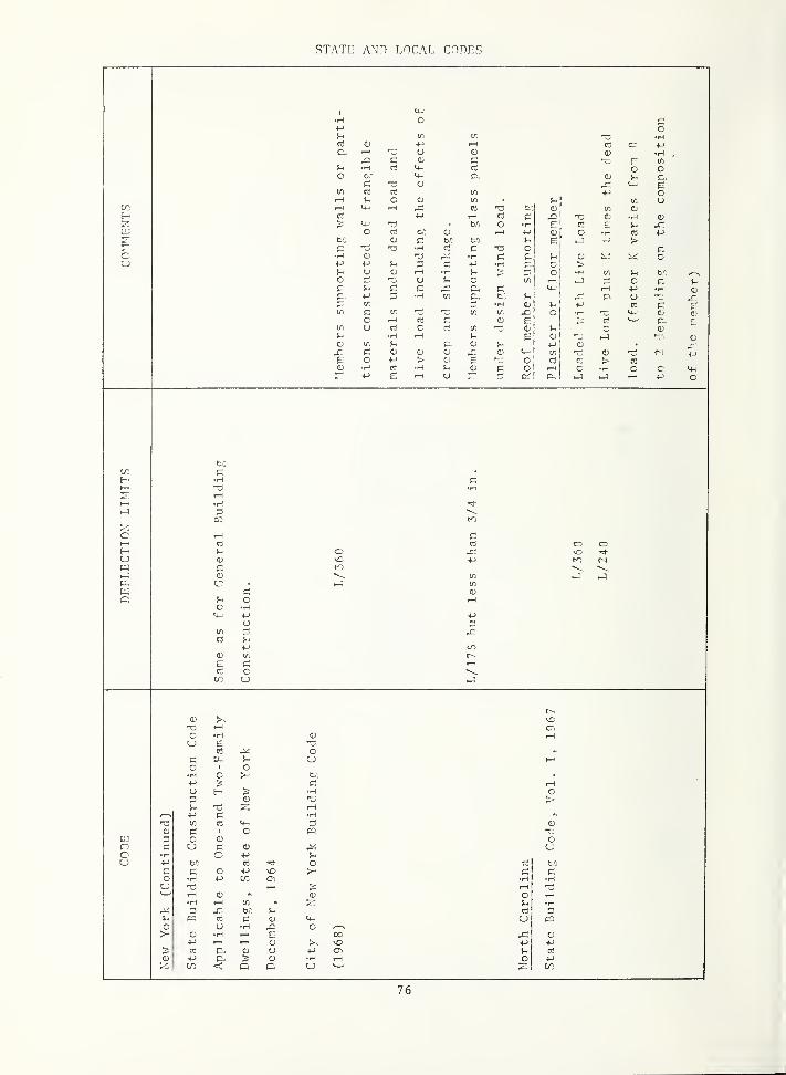
STATE ANn LOCAL COnHS
cu
(/) •H(1) 4-1 oi +->
bl GC no<D
p.. sio
o 1 )
hp t
t/) ct 4_) o,—1 Q !-. ui-H C3 tc O t/1 C)
i-J 1—
1
rt c 0 _J
<+- ,,
to Q •H Ec o •M
1•H +J
O c to in +-1
c •H «' c O c•H £ •H C u oM +-> !-< 'c •M c >in u 1—
1
i-H o •HO u o .-J c cP y- c C r—
1
+-1 o£
+-> c. t: J- P- u(/. •H re cc: 1/1 l/l (/; ° c;
o 1—
<
c CJ 1 t5 p E<j c ri !^ o o
•H 1—
1
O Oo w, !- o oX c O CD o (Li tr o ME o •l-J > C) 'i o > reO rj H !- o C o C •H o c
+-> e 1—
I
U a. o
E-UW-J
bO
3
u o
o iHC HM-
Ct Ut
10
retr LO
(D
E cre cu
o1—1 C,
O - a) i-l
u £ 13re O
c U 1—
1
o o•H o to+-> rHu E- •H O3 £ >^1 13 1—1
•M H(/) re 3
(U 1 c eac o o
d u o•H c +-> Ti+-> b.0 re ^3- o re
C o •4-) vO >- cO •i-i 4-1 •H H
T3 > 1—1 131—1 <D 0) o 1—1
H I—
1
S-i •H3 X- ti S- re 3la rt C 4) u «
o u •H ^ O ^<D •H --1 6 CO Q.)
l-J I—
1
>, \o (-> I-J
re P. 0) u l-J ai re
•M P^ S o •H 1-1 _o I-J
< o c
c
76

STATE AND LOCAL CODLS
CO
c
O 3i-H
fo
Ml« M<D O+J o c de
CD (/) v< o> rJ u
•H u1—1 o
<u oC
tc • •H•H t—
1
in 1—
i
o10 (U t-i HO OJ o OJ M P.
•(-> (= uu^^ rt >.
P. 1—1 0O <D 0 u
tr. I—
1
ai oi-l >M c o
e: to 0) >-iH M P-U o rH U cT
o ^ 101—1 cr (-1 C •H
•H o f=< cn 1—< a M •H
C
C3 oiHto
o u c 0
1—1 (D 4-1
if)
<D II
•xl to ,—
1
1—
I
o c (1)
O p.O
to t/1 c u too o r-
CO •H +-> C 'H1-1 Cj C <4-^ >-i +-> 1—
j
1—
1
> r. C p. c t/^
•H u o1—1 o e +-'
•H iH to o 4:: <u ct(-> E P--I-' u 1—1
O c ft ct p. UH cd •H 0 D <+- 0 1
u 00 e t/) 0 M- +->
o 1 I 0M +-> +-> c
t/! O c c crcS c o c
cc c: c c<D 1—1 CT. I—
(
6cS
(/I J
fc.0
•HiHr-i
O
c cVC
C-. Vi CTj
rH C 1-1
o(D •H
O O cu (_)
C-O cc o
•H uCTi
1—1 1—1 i-i <H •H
e: ec (/; o
o O (/I >.•H H 3 +->
^ O Hc c rr u
P.
OJ
COco
P-
c
c
77

STATE AND LOCAL CnnnS
CO
cu
tn in1—1 c u
( o 0•H •H 0
c +-) .-1
^->ar
1—1 uo
T> p. c rH b".
O o <+- C T3o H O •H c
c i-j +-1 M<D u !-i
+J o 0 in
(= ^ to•H !h C- c
u t/1 rt •HC rt != 1-1 .—
(
o +-> c •H •
•H ^-> u U (D4-1 a (J rt
U !-. 0<D (1) 13 1—1
Si •H 0M f 0 S-tn c rt 0 0) >C O F. 1—1 •f-J •Ho i- a' M-l IT, i—l
urt
o(L>
rt rt
I—
1
Co If, o Cl. tc
o c c M E •Ho £ c rt (A.
I—
1
c (-> 0(7) +J rt PC rt
<0 U
c4-1 <4- d;
1 C 't- 0P^O > M-
0 C CU - C -H
0 0)
0 0ui C 0 <D (3 r--
(/) "C 0 cri
1—
i
0 rHrt .r; u 1-1 U1—
14-) <D rt
in fx c t-C C c4-J -H -iH • C 0
-3 rt 'd U 4-> •H u •HC c; c (=: 13 4-1
rt in 0 -H a) 1—1 1/1 •H 01—1 VO
tn c 4-1 p. <D c D rt
ED U CO P5 •Hrt C t-i (U i-i ud) -H c ^ 0 U •H 4-)
I--", PC +j 1+^ +j M-j HI
0c
in
rt
PCc
•H
0 tn c rt
rt •1-! u13
1—
i
0) 1—1
•H 0)
p) rt D CLO PC <
c
13
ts•H (U4J <u
C in
10 >U 0UU at
0 4; ^^
•H H 4-»
in
0in
iHp;
•Hdi
"p.
e 0 <_o U
< CD P3to •H H Oi
t/i (3 in in I—
1
0 in 0 •H C C(U 13 0 0c >N 1—1 u u <D
4-> (3 4-1 •H in in T3•H OJ •H 3 •H •H 0U P3 U
78

APPENDIX B,
Summary of Vertical Deflection Limitat
in
Foreign Codes and Standards
79

c
|2 be rt
l/l oto ,0 M
rt O o <D1—
1
t—
1
10UU
•H•M
!-<
rt rt <D
of uUt
CO c C- 4-)
X. o E U•H •M H O (Ut:: p. +-» ur3 <L> rt cC TJ 4-' rt (U
O•HE (is
> •H CD
t—
1
<D4-) H o 4-1
U "4- 4->
(D >c O •H
c U-(D to rt > t/l
U Oc rt II II £,o I—
1
u m O
O O rtto LO VC *
to pV 1 V 1 V ! o c
U •rt
0 Ph p
—J I—
]
c O to
"7"4-J
<D ,P'—
'
to o E /-^ Pi UC 4-' <D * * rto •H rt E <D <D!h E •H •H *
4-1 •H to CD c o P10 T-H PI > •H TO O •rt
LJ 0 < . •H uu Clj p ^
'—
'
H >^ M-! Ort 4-* O c O o J- 4~> Sh tj
•H c o in O >-i
C 1—
1
\o c O M-J O•H •H o
^ •H J u trt
+-> rt 1—
1
rt
o <D •H >. G UU ^ rt ^-1 -rt
•H •H 3 4->
4-) > t 4-) <D>-< (D o C rt
(U c C 5- rtifl C H o x:
M P,•rt i-i
rrt rt
t O P4-" -rt
1—
1
•H(= trt in -t;
Pi O O O< o cc •rt "Si- (D t/;
o to U •rt
< •H ec r-l
H c > t/> 2-. to
u o •rt C 4-) Oi-> l-l
(/I P- C* rt
C o C 0) U10 P- 4-1 rt X)
I3 •H CJ >- Pc 4-> o u rt
c u « 4-" u3 4-> r; P tfi
fi to o •rt p4-1 t—
1
« c u om •rt c (/) -rt
OO ort rH rt •rt o 0 O•H (1) •H rt 4-> u ^ 0i-H t—
1
rt o rt !- e t«
rt rt •H I—
1
OU !-< u t/1
+-I oo 4-J 4-> C C LTi
to < VO 01 to 4-1 rt •rt
< CTl o 5- <D CTl
< C/0 t—
1
< < c 4-> t—
1
80
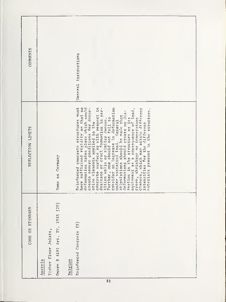
CO
l/l
Hi
Q<^Q ^, )
U O34-*
•H
03
CD
4-) O Ti ' *
T> Pi (D
t—'w-i o3 O
E 4"* O O 4-) C Tj XJ l^J
,. * ' ^ ^ \L IIj
O f-i
c3 Oill /l"- J_l CT —J (—
'
U,> '4—' t; r~i ' fn M—
'
Ofli O ti—( I_j rr( XJ ^3
J-" U ^C/} +^ ^ t, 'rn \U
t . rr* fT* rt^ ^ f—' f\\W Cu w C v-« UJ O d) fn t/1
f 1 > /~\ ,_j * 1 1 FT—* /II i~w j_ J'rn O ^> tv- T—
'
U G C CZ3 ^^-^ to J 1
<—' j_j r ~ IT* IT* O C P *H U-J
J 1 (t' «. J_) W /1^+—' ^.L i— }^ vU M TO4-> ( CJ O rr* (11 t,
^w* *~ p:; \_/ *r-\ w ^wj w n fll , 1 r* • r 1^ fH t~-a
•
^ T-i \j V) Hi L«* O i_3 cn M (U •H>-< P; C >.rPl
»—M ^—1 l/J l~1 ,—1 _J ^ R /I,^ ^
t\j w vJ ^ ^ Uj tj O £ Pir-^ \J o
<-< rrl»-i >-t TO UJ TO TO LJ to
cd O fl> J_J fll d)^-J I/!
U Pl <D M Lj —t r" r"" rri\J ^ t-i t~\ TO >^ ^ ^ «^ pj-t^ tr\ I 1 O rr* J 1/—
\
Pi Uj l~1 V_> TO "I—" P, H 2 u)vL" TO U) '"^ ^ *rl
t/J
U 1^ ^ ' \U \U ^ ,—' i— ' P, u) 4-*
w ^1 3 rt o f-< 0) t/i CO P: <D if) *HC l/l E CD fl'' rrt f"* fl^ n-f ^-1
•H p. be p; u<u C (D C CC > U -H -H 4-J C/l <D p. O +J O C (D oe •H > 0) Z3 <D -P !->
0) CC <D mojh.hdop:-i-jc; c cr ^-i X p: c;CO p:^ X U 4-J O U U "H E
. .
<\—
Ln
\—'
*~
t
—
\ t/j*
I—
1
*^ Jh
o o O,
—
•
oJ-
oo rr-<
Ou
<A E u•H cJ-i s •Hl-> J-l
t« E o I—
1
•H•H c o
< H o PC
81

t/l
(-1
oot-H (/Im
1 mU in
'ITS
o o tomc
rue flo rin
1—
^
o 0•H t/l >
c vert
UT COto
t+-:
o o CO o +J O4-> I-H I-H u <+-! o
• iM o to o o uo 4-> CD •H o p. oc. •M I-H
<D u •H >. ceu •(-> •M VI u +-»
> ca u •H 0:^
o o ri I-H (/) •M e1—1 I-H 0 I-H
>—
1
'd •H rt <D +-> 4-)
£..
c0X nt ve th
E asC-
ee
•H •H •H •H o 1—
1
U <
t—
V
o >-W ?
to
1
^1 r-H 00 c: c4-1 o
LO1^
0U0
+->
•H
0I-H
t/5
t/l Eto ctf
0 C, ot/l
t4-.
•H4-i
!/:
o c o O cu CO
(NI r-H
0
(XI
3o E\c to
u to too o r-H
>-] •H c •H o o1—
1
0 o oU V- U
<4-'
0n
c 4->
r uCT, 3< -H
4->
<?to 0
c/:
Kl et
CNl uO <one
o u
0£ u
C+-> O o
•H4->
!=; < •H Uty: 0 0tLJ c-i
r-l
t;03 !—
I
•H
U< t-
t:^
4-1
O 1—1 C/j t/l
0to (3^ •H
o c \C T3u tiI—
1
J-
J.
t5 c 1
C •H VC fC•H LO 1—1
c Vl 5-1
i-H 1—1 O•H 4-1
d c 1-H uo 03 to
u 0 COr-H 0 Uc3 CT. cC o 4-> +J oO •M CO U •H•H O 4-1 4J+-> U <r U U03 0 CO 4-1 07^. 1—1 CJ 00 CO
82

83

HO
H-i'
4-*
•HE
•HCO 1—1
E—
'
?T coti 0
c (J
QJ U <D1—
1
4-*
f-i
cu 0Ph
*C-.
•H —
'
cC t- 0 >0 cC f-H CJ1-H <D 1—1
X! I-H •HCD 4-J
> rH•H T—
{
•Hcr CO
u QJ 1•
•H 0 S-^ t/l
+J 4-* 4-* cS i~H
O 0^ U M— cti t/i
»r> J 1 ^1 /~i r"* J 1Uj 4—' U +-*
V)
— O rH|3 'H 0 0 4-' I/)
4-* bO'X^ *H <U
h—
1
•H L) 'H 4-* L) L> U 0''
^ t. . ri—! rr' rr" er'^ M t\, u!/1
—
1—
(
H 4-J p.. >-H "4- 0 4—'
»-J 4-' 4-* Cw U Cti D•H i-H C <D U ^
•-->-
C> t/l *-|—! QJ (/I
J-* ^>
t—
'
o O 4-* C-) 0 U ^ C •r-(
•H 0 'H •(—( 'H do r3
4-* to
u to U ^-f— v3 TO M r-< #H 4-'
1—] P .-f t; CJ GJ P-( CJ •HC J-< EH *'
C|—
:
u 0 to «H'—
'
<3J ^ U 5-« 0 1^ i-H
' T I J> CJ 'iH 0 T-H »—-3 CJ
o l/l
CJ ^ ^ Jh ^ t/l M-H C+-> 5h 4-> 4-> :3 0u •H 0 C t-c 4->
<D n:; ti-* r-j <D C U C t/j 10
rH f-H C > C c> :^ .H cr. tn crH •H C 0 C Jh 4-J •H Pi iH
QJ tH 4-* 4-* 'iH 4-* CJ (D
1—
(
[_J^ U) y 1T—' UJ UJ ' CO 4-J
•H •H
1—
1
CJ •HCD ^3
CC0^ CA.
•< ' .r^I—
1
LO OC o~i •H1—
(
t—
1
\C•< J-" cr. CD
H f-H 4-*
CO c O CD
(-H U •H f-i
^ fn CJ
C u U (N]
f-H o Cw CO CO P 4-'
C in r;
03 O.
- 'O 0 c(D L)
<D Uc
0 0cd r; •H
O 1—
i
1—
i
t->
0 uCO 13 q; C- C- cu
pr. 0
84
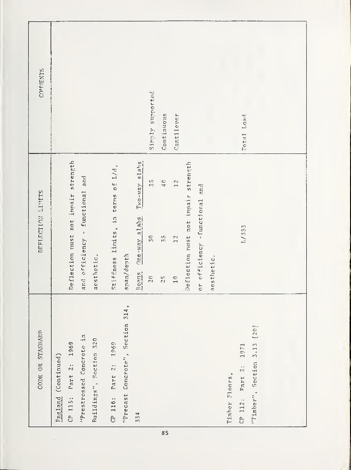
CO
C<D
•P
OP-g. ir. tin 5 > o
<u -J>. iH1—
(
•H •H r-lM +-> ej
c 4->
•H o ou U
i/i
)-> ^:to r! Ct
1—
1
(U in
y> (=:
t-j >st/^ o
to 1—
1
>H (h OJ 1/) 1
1—
1
•H C E Oc3 o •>
1—
1
P, •HE
•H Ct
c (/)
C (-> 3 •HO
i-f
EC tst/i
(/; >^ •HP-, U E
E c •H •?
o I-H
!=! •H (DO u u p;
•H •H -H p. cP 4-1 oU <4- <D
(D O ^i-H M M-- c E
• 1-^
d) c o M p. oc m P5
Jtr.
p;<p
P(4-1
inan
u•H
P, CE o•H
ti
4-1 uO p:
p; tnK)
M 1
Ency
Cc •H U
•H u •H4-> •H 4-1
U <+-
(D
rH (D 4-1
<4-^ W,
CJ !h oa O ct
I-H
K1
P +J
< •H c uc Oi (DvO C CO< cri 4-1 c.t-H O P
Pi c<D U •H "o)
D P 4-1 4-1
o C r-o O U o•H u <D p.w 4-1 4-> t/: 4-1 oc p: Pi Pi co o CC CJ a ou P. 1/) P- CJ
01 t/i
(D fcC 4-1
13 Pi c </)
p; LO 4-1 •H \D rtI-H (/) 13 1—
(
uiH I—
1
<D I-H I-H obc Pi •H Pi
c; P. O, (X Phu Kl
r-H
r~- I-H
oi-H Kl
co
fV! •H4-1
in 4-1 Up P OJ
o c3 too P-rHPL,
pP (U
CD i-H -Q1-H E
E H•H tx
85

/
Pi<
oo
<H <U
to M<U5-
C UC
tq OC UCU
ou
CI ouc cCS •HSi <u[In Ci
86

87

COH
cu
<D
iHrQrt
S-<
(U
CC U •HCD 4-1 o
o M crt
m c CO
o U o ou (D M •H 4-1
•i-i 4-1 o M<4-- o
<+~ CC —
t
<D
o i-> ^ ib Ct
> OJ
t/) If)
03 p o !->
m •H O oi
bf: •H (-> ce c u I/) Oo o o •H
•H >-< 4-1
c; Si •Hr-l (J- .-I o o t/) O0.-: o I— > o O
o o •H 1—1 c r-t •Hu u tL, >
e
u
I
ocr oo
CO
4->
<
Ert
c/:
V I
-J
^<
o
oc
cr
\o
< rH COCO to
^'CC <D
0) CT, LO rHCO 4-> 4-> +-I U
o 10 0) 10 •H•H t-H •H 4->
o c U c u O•H c •H h-
^
<•p o 4-)
P; e; CJ }h
c o o < o LO
u o o I-O
r-i t—
1
CT-.
u i-H
Lno o
ce i-i PC
6•H e 6CD •H t—i o •H
u C-< O
88

CD
c
C c c1—
1
(Nl
o•1-1 in (/)
.J »->
a 03 "cC
u 1—1 1—
(
C uz CO
•P
c. ca' TTo (D
—] (~ e r (->
1 O o ^e o o O O
p: c P,1 I/: £,
c: c >> (Dct !h CO c cr. C
to & •H •Hrt CJ >.
£ .—1 ^1 I—
1
(D c o 4-1 c •1-1
E •H u E cr. e:c; 0) •H O •H <U
c/; 0? cr;
<
<IT, 0)
inSt
(->
<u•H
c onc
oc,c c uo
flo
cr,
1—1reed
oo
3: X- 03 cE I—
1
•Hc •H CO O
H cu
89

H
ou
>H 4-1
1 U1 oc: t/5
o <b wc be
A
\^
nt
fc.: o •Ho
•H ip4-J 6 Oi-i P!O (-> (1>
u .—1 <0
CI. •H 15to •p
re be nt an
l/l fiI—
1
e 10I-^ to O ocC (/I C 6
03 o•H p c
ot';
o Ti 5- C> (U u •H O c
•H •H tc o 'Tl M 1—
1
tr, ft I—
1
ir rt ci II II
o-J
4-^
OP
to rH tD<D c o •Hu to P
E- p tu p1—
1
to O Cp ^1 o •H cc <u P Jl ECD 1-H X o p. to p.C •H o to c P •Ho to I-H o to rt u
c C •H p. CD C1—
1
0) P p; M- 0CT
1^1 c
anp c
•Hrt
Piu
noC•H
<PO to
u:1
<D x; P PJ (0 to i-H o p to CTi <D •Hpt- to II p •H <D I—
1
<D E <L> to uc C•H O cr
tonnwii U "rt o
U •H rH c •H ID •H CD
•H X t—
1
o P IT,
rt C3 u t-H rt CD 13H EII to
to
toE P
•H cPU
II E P o cCC rt O tpt-H __ip (U 1—
1
o o tp Por; D P5 ci E o to
c<
<(/:
c
o
opCD
uu
ou
CD
uu
c oCD tp•X} po
oto
90

91

a;
c
<^*
E-c/:
c
c
O
o
u
in
E
t-C
C
4-1
Uo
rt
I
CC
5
P0!-i
Ucou
•H <u
> ua ^I—
1
oin ^-^
O c•H
3 (1)
92

APPENDIX C
Steel floor joist vibration formulas were developed by Lenzen [113].*The steel j oist - concrete slab floor system was assumed to act as a two-wayplate system under vibratory excitation from human activity. Only anequivalent number of joists, N, are assumed to participate in the vibration,where
where
where
N =
n =
N =
X .=
n X.
1 + 2 T. cos IT -j^i = 1 o
Cic)
1, 2, . . .n, number of joist in floor under consideration
equivalent number of full effective joists
= distance from the center joist to the joist under consideration
= distance from the center joist to the edge of the effective
floor, whereV - 3 YTe L^o 3
L =
D =X
D =
1/4
(2C)
(3C)length of joist and e = (D^/D^)
flexural stiffness perpendicular to the joist (slab only)
flexural stiffness parallel to the joists (composite section).
The flexural stiffness perpendicular to the joists is the stiffnessof a unit width of the concrete slab or
where
^c'
12
= modulus of elasticity of concrete
(4C)
t = slab thickness
The flexural stiffness parallel to the joists is determined from theformula
E I
Dy
(5C)
where I is the moment of inertia of a composite section consisting of onesteel jSist and the concrete slab of width, b, where b is the effectiveslab width which usually is equal to the joist spacing. is determinedby converting the slab to an equivalent steel element by reducing itswidth, b, to bg = b E /E.
* Numbers in brackets refer to literature references. References aregrouped in the respective report sections and are listed in alphabeticalorder in each section.
93

The floor will behave dynamically as a simply supported equivalentflexural beam consisting of N joists, thus its dynamic properties can bedetermined much more easily than the dynamic properties of an orthotropicslab. The beam has an equivalent flexural stiffness of
"equ= N I (6C)
and an equivalent mass of
equ (7C)
where w is the weight per unit length of one joist and the slab of widthequal to the joist spacing, and g is the acceleration due to gravity.
The natural frequency of the equivalent beam can be determined fromthe flexure formula for a beam
fn =
2L
(8C)
equ 2L
Human response to vibrating floors depends not only on the frequencyof vibration but also on the amplitude of the deflection due to impact.Lenzen used: 1) an impactor, consisting of a cylindrical steel weightof 3155 lbs in a vertical frame; and 2) a heel drop on the floor by ahuman. These two methods of excitation gave distinctly different responsesin the floors. The first impact, due to the mechanical impactor, wasapproximated by a rectangular pulse having a force of 794 lbs and aduration of 0.01 seconds, (F = 794 and ti = 0.01). The correspondingmaximum amplitude at the center of the effective floor area is givenas where
and
where
4 F L
IT N E I
4 F L
for t < t^C9C)
TT N E I
sin IT f tj for t > tjn a o ci
(IOC)
= first maximum amplitude, in.,
F = force of rectangular impulse, lbs.,
L = length of joist, in.,
N = equivalent number of full effective joists
= moment of inertia of one joist and its slab, acting compositely,
in6
E = modulus of elasticity of steel, E = 29 x 10 psi
f = natural frequency (eq. 8C)
94

= duration of impulse
= time to occurrence of maximum amplitude,
t =o
1
TT(llC)
The impact due to the human heel drop was approximated by a triangularimpulse of duration, t, and maximum force, F, and the values of t^ = 0.05seconds and F = 606 Ids were used. The maximum amplitude at time t^ is
2 F L
TT E N I.
C2 for t < t,o — d
(12C)
whereTT f.
tan-1
(2 - fn ^d)(13C)
and2 F L
TT E N I \ 2 TT f t 1c \ n d
r2 [1 - 2 TT fj^t^ sin 2 ti f^t^ - cos 2 tt f^t^J + [2 tt f^t7^1
-n"d nM- -n^d-
for t„ > t,o a
(14C)
wheret =o (--1 tan
1 - cos 2 TT fj^t^
sin2TTft,-2TTf„t,no. n d
(15C)
* U. S. GOVERNMENT PRINTING OFFICE : 1973—542-650/59
95

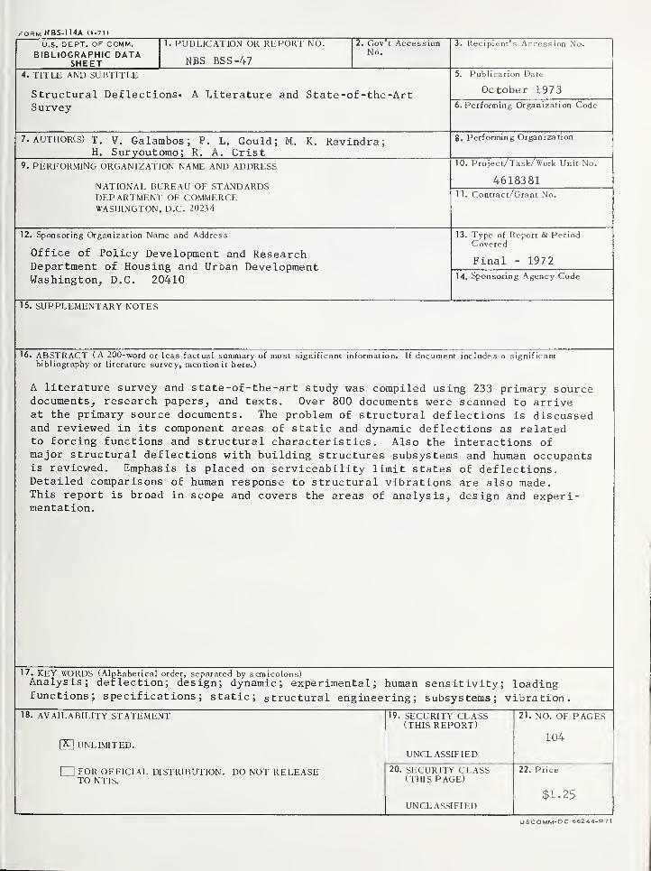
rORM NBS-114A (1-71)
U.S. DEPT. OF COMM.BIBLIOGRAPHIC DATA
SHEET
1. PUBLICATION OR REPORT NO.
NBS BSS-47
2. Gov't AccessionNo.
3. Recipient's Accession No.
4. TITLE AND SUBTITLE
Structural Deflections* A Literature and State -of -the -ArtSurvey
5. Publication Date
October 1973
6. Performing Organization Code
7. AUTHOR(s) T. V. Galambos; P. L. Gould; M. K. Ravindra;H. Suryoutomo; R. A. Crist
8. Performing Organization
9, PERFORMING ORGANIZATION NAME AND ADDRESS
NATIONAL BUREAU OF STANDARDSDEPARTMENT OF COMMERCEWASHINGTON, D.C. 20234
10. Project/Task/ Work Unit No.
461838111. Contract/Grant No.
12. Sponsoring Organization Name and Address
Office of Policy Development and ResearchDepartment of Housing and Urban DevelopmentWashington, D.C. 20410
13. Type of Report & PeriodCovered
Final - 1972
14. Sponsoring Agency Code
15. SUPPLEMENTARY NOTES
16. ABSTRACT (A 200-word or less factual summary of most significant information. If document includes a significantbibliography or literature survey, mention it here.)
A literature survey and state-of-the-art study was compiled using 233 primary sourcedocuments, research papers, and texts. Over 800 documents were scanned to arriveat the primary source documents. The problem of structural deflections is discussedand reviewed in its component areas of static and dynamic deflections as relatedto forcing functions and structural characteristics. Also the interactions ofmajor structural deflections with building structures subsystems and human occupantsis reviewed. Emphasis is placed on serviceability limit states of deflections.Detailed comparisons of human response to structural vibrations are also made.This report is broad in scope and covers the areas of analysis, design and experi-mentation.
17. KEY WORDS (Alphabetical order, separated by semicolons)Analysis; deflection; design; dynamic; experimental; human sensitivity; loadingfunctions; specifications; static; structural engineering; subsystems; vibration,
18. AVAILABILITY STATEMENT
Pn UNLIMITED.
I IFOR OFFICIAL DISTRIBUTION. DO NOT RELEASETO NTIS.
19. SECURITY CLASS(THIS REPORT)
UNCL ASSIFIED
20. SECURITY CLASS(THIS PAGE)
UNCLASSIFIED
21. NO. OF PAGES
104
22. Price
$1.25
USCOMM-DC 66244-P7>

Announcement of New Publications in
Building Science Series
Superintendent of Documents,
U.S. Government Printing Office,
Washington, D.C. 20402
Dear Sir:
Please add my name to the announcemenit list of new publications to be
issued in the series : National Bureau of Standards Building Science Series.
Name
Company
Ajddress . . .
City Staite Zip Code
(Notification key N-339)

NBS TECHNICAL PUBLICATIONS
PERIODICALS
JOURNAL OF RESEARCH reports National
Bureau of Standards research and development in
physics, mathematics, and chemistry. Comprehensive
scientific papers give complete details of the work,
including laboratory data, experimental procedures,
and theoretical and mathematical analyses. Illustrated
with photographs, drawings, and charts. Includes
listings of other NBS papers as issued.
Published in two sectiovs, available separately:
• Physics and Chemistry (Section A)
Papers of interest primarily to scientists working in
these fields. This section covers a broad range of
physical and chemical research, with major emphasis
on standards of physical measurement, fundamental
constants, and properties of matter. Issued six times
a year. Annual subscription: Domestic, $17.00; For-
eign, $21.25.
• Mathematical Sciences (Section B)
Studies and compilations designed mainly for the
mathematician and theoretical physicist. Topics in
mathematical statistics, theory of experiment design,
numerical analysis, theoretical physics and chemistry,
logical design and programming of computers andcomputer systems. Short numerical tables. Issued quar-
terly. Annual subscription: Domestic, $9.00; Foreign,
$11.25.
DIMENSIONS, NBS
The best single source of information concerning the
Bureau's measurement, research, developmental, co-
operative, and publication activities, this monthlypublication is designed for the layman and also for
the industry-oriented individual whose daily workinvolves intimate contact with science and technology—for engineers, chemists, physicists, research man-agers, product-development managers, and companyexecutives. Annual subscription: Domestic, $6.50; For-
eign, $8.25.
NONPERIODICALS
Applied Mathematics Series. Mathematical tables,
manuals, and studies.
Building Science Series. Research results, test
methods, and performance criteria of building ma-terials, components, systems, and structures.
Handbooks. Recommended codes of engineering
and industrial practice (including safety codes) de-
veloped in cooperation with interested industries,
professional organizations, and regulatory bodies.
Special Publications. Proceedings of NBS confer-
ences, bibliographies, annual reports, wall charts,
pamphlets, etc.
Monographs. Major contributions to the technical
literature on various subjects related to the Bureau's
scientific and technical activities.
National Standard Reference Data Series.
NSRDS provides quantitative data on the physical
and chemical properties of materials, compiled from
the world's literature and critically evaluated.
Product Standards. Provide requirements for sizes,
types, quality, and methods for testing various indus-
trial products. , These standards are developed co-
operatively with interested Government and industry
groups and provide the basis for common understand-
ing of product characteristics for both buyers and
sellers. Their use is voluntary.
Technical Notes. This series consists of communi-cations and reports (covering both other-agency and
NBS-sponsored work) of limited or transitory interest.
Federal Information Processing StandardsPublications. This series is the official publication
within the Federal Government for information onstandards adopted and promulgated under the Public
Law 89-306, and Bureau of the Budget Circular A-86entitled, Standardization of Data Elements and Codesin Data Systems.
Consumer Information Series. Practical informa-
tion, based on NBS research and experience, cover-
ing areas of interest to the consumer. Easily under-
standable language and illustrations provide useful
background knowledge for shopping in today's tech-
nological marketplace.
BIBLIOGRAPHIC SUBSCRIPTION SERVICESThe following current-awareness and literature-survey bibliographies are issued periodically by the
Bureau
:
Cryogenic Data Center Current Awareness Service (Publications and Reports of Interest in Cryogenics).
A literature survey issued weekly, .Annual subscription : Domestic, $20.00; foreign, $25.00.
Liqueiied Natural Gas. A literature survey issued quarterly. Annual subscription: $20.00.
Superconducting Devices and Materials. A literature survey issued quarterly. Annual subscription: $20.00.
Send subscription orders and remittances for the preceding bibliographic services to the U.S. Department
of Commerce, National Technical Information Service, Springfield, Va. 22151.
Electromagnetic Metrology Current Awareness Service (Abstracts of Selected Articles on Measurement
Techniques and Standards of Electromagnetic Quantities from D-C to Millimeter-Wave Frequencies). Issued
monthly. Annual subscription: $100.00 (Special rates for multi-subscriptions). Send subscription order and
remittance to the Electromagnetic Metrology Information Center, Electromagnetics Division, National Bureau
of Standards, Boulder, Colo. 80302.
Order NBS publications (except Bibliographic Subscription Services)
from : Superintendent of Documents, Government Printing Office, Wash-
ington, D.C. 20402.

U.S. DEPARTMENT OF COMMERCENational Bureau of StandardsWashington. D C. 20234
OFFICIAL BUSINESS
POSTAGE AND FEES PAIDU.S. DEPARTMENT OF COMMERCE
COM-2 1 5
Penalty for Private Use. S30G