structural design 1. semester - nicolaigreen.dk · 2016-08-05 · structural design gitte normann...
TRANSCRIPT

Structural design
Gitte Normann Bak
1. semester
Rev. 16.04.08 – 1 –
Table of contents
1 Physically dimensions and SI-system ................................................................................. 3
1.1 The SI-system ............................................................................................................... 3
2 Mass and density ................................................................................................................. 5
2.1 Density for gases at 00C and 760 mm Hg. ................................................................... 6
2.2 Density for liquid and solids .......................................................................................... 6
2.3 Example: ........................................................................................................................ 7
2.4 Example: ........................................................................................................................ 7
2.5 Exercises ....................................................................................................................... 8
3 Forces ................................................................................................................................... 9
3.1 Vectors ........................................................................................................................... 9
3.2 Analytic solution........................................................................................................... 13
3.3 Excercises ................................................................................................................... 15
4 Equilibrium .......................................................................................................................... 16
4.1 Example: ...................................................................................................................... 16
4.2 Example: ...................................................................................................................... 16
4.3 Example: ...................................................................................................................... 17
4.4 Exercises ..................................................................................................................... 18
5 Moments ............................................................................................................................. 19
5.1 Example: ...................................................................................................................... 19
5.2 Example: ...................................................................................................................... 20
5.3 Two forces or more ..................................................................................................... 21
5.4 Parallel forces .............................................................................................................. 21
5.5 Pair of forces ............................................................................................................... 23
5.6 Parallel displacement of forces ................................................................................... 23
5.7 Equilibrium ................................................................................................................... 24

Rev. 16.04.08 – 2 –
5.8 Exercises ..................................................................................................................... 27
6 Supports: ............................................................................................................................ 29
6.1 Calculation of the reactions:........................................................................................ 30
6.2 Exercises ..................................................................................................................... 32
7 Properties of structural materials ....................................................................................... 34
7.1 Introduction: ................................................................................................................. 34
7.2 Stress: .......................................................................................................................... 34
7.3 Strain:........................................................................................................................... 34
7.4 Modulus of elasticity: ................................................................................................... 35
7.5 Strength and stiffness: ................................................................................................ 35
7.6 Mild steel:..................................................................................................................... 36
7.7 High yield steel: ........................................................................................................... 37
7.8 Timber: ......................................................................................................................... 38
7.9 Exercises ..................................................................................................................... 39
Rev. 16.04.08 – 3 –
1 Physically dimensions and SI-system
All physically dimensions have a definite term. “l” and “s” = length, “t” = time and “m” =
mass. A numerical value, a unit and sometimes a direction indicator determine them.
The EU- countries have decided to use the SI-system.
Sometimes the physically dimensions gives an inconvenient numerical value, and therefore we use powers of 10.
1 m³ = 1.000.000.000 = 109 mm³ (cubic metre)
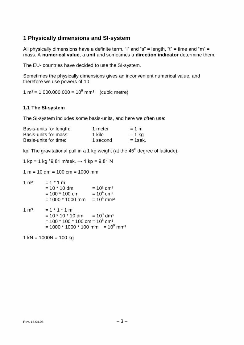
1.1 The SI-system
The SI-system includes some basis-units, and here we often use:
Basis-units for length: 1 meter = 1 m
Basis-units for mass: 1 kilo = 1 kg Basis-units for time: 1 second = 1sek.
kp: The gravitational pull in a 1 kg weight (at the 450 degree of latitude).
1 kp = 1 kg *9,81 m/sek. → 1 kp = 9,81 N
1 m = 10 dm = 100 cm = 1000 mm
1 m² = 1 * 1 m = 10 * 10 dm = 10² dm² = 100 * 100 cm = 104 cm²
= 1000 * 1000 mm = 106 mm²
1 m³ = 1 * 1 * 1 m
= 10 * 10 * 10 dm = 103 dm³ = 100 * 100 * 100 cm = 106 cm³ = 1000 * 1000 * 100 mm = 109 mm³
1 kN = 1000N = 100 kg

Rev. 16.04.08 – 4 –
Physically
dimensions
Symbol SI-unit Definition Conversion
Length s m 1m (basis-unit) 1 km = 10³ m, 1 m =10² cm
Mass m kg 1 kg (basis-unit) 1 t = 10³ kg, 1 kg = 10³ g
Time t sek. 1 sek. (basis-unit) 1 hour = 60 min.,
1 min. = 60 sek.
Density d
³m
kg
V
md , (V = volume)
³³³10
cm
g
m
kg
Velocity v
sek
m
t
sv
hour
km
sek
m6,31
Acceleration a
²sek
m
t
vva t 0
Force F N (Newton)
F = m*a 1 kp = 9,81 N
Moment M Nm M = F*a (a = distance)
Pressure p Pa
(Pascal)
²11
m
nPa

Mass and density
REV. 16.04.08 – 5 –
2 Mass and density
A solid does always resist when it’s motion are changed. The solids are slow – because of
its mass.
The unit for mass is 1 kg.
Density is the relationship between the mass of the solid and its volume V.
Waters density is 10³ kg/m³.
d – density [kg/m³] V
md
m – mass [kg] Vdm *
V – Volume [m³] d
mV
Solids expand when they are heated and condense when they are cooled down.
The mass is independent of the temperature, which means that the density gets smaller when the temperature is rising (The same mass have a bigger volume).
³10
³10
10
³1 3
6
3
m
kg
m
kg
cm
g

Mass and density
REV. 16.04.08 – 6 –
2.1 Density for gases at 00C and 760 mm Hg.
Gas density
[kg/m³]
Oxygen 1,429
Hydrogen 0,090
Carbon dioxide 1,977
Carbon oxide 1,250
Nitrogen 1,251
Chlorine 3,214
Ammonia 0,771
Atmospheric air 1,293
2.2 Density for liquid and solids
Liquid and solids
density
[g/cm³]
Water (40C) 1
Alcohol (180C) 0,789
Ether (180C) 0,717
Mercury (00C) 13,596
Ice 0,92
Wood 0,4-1
Glass 2,4-2,6
Cork 0,24
Aluminium 2,7
Iron 7,8
Copper 8,9
Zinc 7,1
Lead 11,3
Silver 10,5
Gold 19,3
Platinum 21,4

Mass and density
REV. 16.04.08 – 7 –
2.3 Example:
Calculate the length of the sides on an ice cube, which mass is 14,375 kg
Solution:
³920
m
kgd is
x m
³0156,0920
375,14m
d
mV
mx 25,00156,03 x m
x m
2.4 Example:
Calculate the mass of a hollow steel sphere. The inside diameter is 4 cm and the external diameter is 5 cm.
Solution:
³7800
m
kgd steel
³**3
4rVsphere
³10*19,3³02,0³025,0**3
4 5 mV
kgVdm 249,010*19,3*7800* 5

Mass and density
REV. 16.04.08 – 8 –
2.5 Exercises
1. Calculate the density of a solid, if it has a mass of 834 g and a volume of 117,5 cm³
2. Calculate the density of a solid, if it has a mass of 2,84 kg and a volume of 1,05 dm³
3. Calculate the mass of 32 cm³ zinc.
4. Calculate the volume of 68 kg lead.
5. A vessel has a bottom area of 14 cm². It is filled with mercury in a height of 8 cm.
Calculate the mass of the mercury.
6. A vessel has a bottom area of 238 cm². It is filled with 3,4 kg alcohol.
Calculate the height of alcohol in the vessel.
7. A vessel filled with water (4oC) has a total mass of 0,415 kg. The mass of the vessel is 0,015 kg.
When the vessel is filled with acetone the total mass is 0,33 kg.
Calculate the density of acetone.
8. Calculate the mass of an aluminium-wire, with a length of 2 km and a cross section of 2 cm²
9. The mass of a gold bar is 500 g. Calculate the volume.
10. The mass of a sphere is 8,432 kg and the density is 7,3 g/cm³
Calculate the radius of the sphere.
Volume of a sphere: 3**3
4r

Forces
– 9 –
3 Forces
We are going to learn about statics or simple statics. This means that we are only
concerned with forces applied on constructions, which are not moving, they are said to be in statical equilibrium.
The loads acting on a structure have a mass, which is usually measured in kg. We convert the mass into a force. Basic unit of force is the N.
The mass of a body, measured in kg, is a fundamental measure of quantity and is related to the number of atoms of material present. This means that a beam would have exactly the same mass on earth as it would have on the moon.
But the force that it exerts if you put it on your shoulder, would be six times greater on earth than on the moon, because of earth’s greater gravitational pull. Gravity is measured
as the acceleration (g) that it imparts (give) to a falling body, and on earth can be taken as 9,81 m/s².
From Newton’s second law of motion: Force = mass x acceleration and 1 N = force to accelerate 1 kg at 1 m/s²
Therefore on earth, the force exerted by a mass of 1 kg is: Force = 1 x g = 1 kg x 9,81m/s² = 9,81N
For many structural loads this is rather a small unit; therefore it is common to use the kN: 1 kN = 1000 N
As for constructing buildings we are dealing with heavy loads, and we will use our own definition of: 1000 N = 1 kN ~ 100 kg
To ease the remembrance of this we also say that 1 kN ~ one big person and 1 N ~ an apple.
3.1 Vectors
Because the force has both a magnitude and a direction, it is a vector quantity.
We usually use the vector definition from the mathematics, which is an arrow, where the length describe the magnitude of the force and the arrowhead is pointing in the direction of action.
The following is needed to determine the action of a force:
1. The point of attack
2. The direction of the force
3. The magnitude of the force.

Forces
– 10 –
A complete description could be:
Attacking at: (x,y) = (2,1)
Direction: At an angel of 350
Magnitude: F = 25 kN
Furthermore we have some basic rules:
A force can be freely displaced in its line of action (it doesn't matter where you pull at a cord, it is the same movement you get).
Two forces of the same magnitude, but opposite direction of attack neutralize each other.
F1 = F2
F1 + F2 = 0
Two forces F1 and F2, attacking at the same point (or at the same line), can be added and replaced by only one force – R the resultant.
The resultant is the force that exerts the same magnitude and direction at a solid, as the other forces altogether. This means that the resultant can take the place of all the forces.
R = F3 + F2 – F1

Forces
– 11 –
Forces are added randomly after each other, and the resultant is drawn from the starting point of the first added force to the ending point of the last added force.
The resultant can also be drawn as the diagonal in a parallelogram:
You can use both ways of finding the resultant though there are more than two forces:

Forces
– 12 –
If the forces don’t have the same point of attack and don’t lying in the same line, you can find the resultant if you move the forces to the intersection of the lines:
We are now able to find the resultant of two or more forces. If we go the opposite way we also are able to break the resultant up in two forces. We usually break the force / resultant up in a vertical force and a horizontal force:

Forces
– 13 –
3.2 Analytic solution
Instead of finding the resultant by painting, we are now going to calculate it, because it is much more precise.
Hypotenuse
OppositeSin
sin*FV
F
VSin
Hypotenuse
AdjecentCos
cos*FH
F
HSin
3.2.1 Example:
α = 300, F = 1300 N
V = 1300 * sin 300 = 650 N
H = 1300 * cos 300 = 1126 N
We can check the result if we use the Pythagorean theorem:
NR 13001126650 22
We are now going to calculate the resultant of several forces, witch all go through the same point:
↑ΣV = F1*sinα1+ F2*sinα2+ F3*sinα3- F4*sinα4
ΣH = -F1*cosα1+ F2*cosα2+ F3*cosα3+F4*cosα4
→
Forces
– 14 –
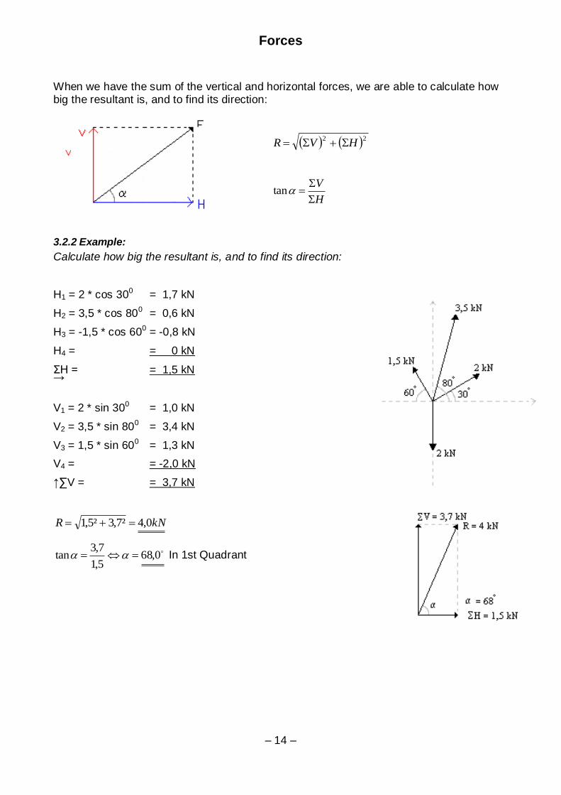
When we have the sum of the vertical and horizontal forces, we are able to calculate how big the resultant is, and to find its direction:
22HVR
H
V
tan
3.2.2 Example:
Calculate how big the resultant is, and to find its direction:
H1 = 2 * cos 300 = 1,7 kN
H2 = 3,5 * cos 800 = 0,6 kN
H3 = -1,5 * cos 600 = -0,8 kN
H4 = = 0 kN
ΣH = = 1,5 kN →
V1 = 2 * sin 300 = 1,0 kN
V2 = 3,5 * sin 800 = 3,4 kN
V3 = 1,5 * sin 600 = 1,3 kN
V4 = = -2,0 kN
↑∑V = = 3,7 kN
kNR 0,4²7,3²5,1
0,685,1
7,3tan In 1st Quadrant
Forces
– 15 –
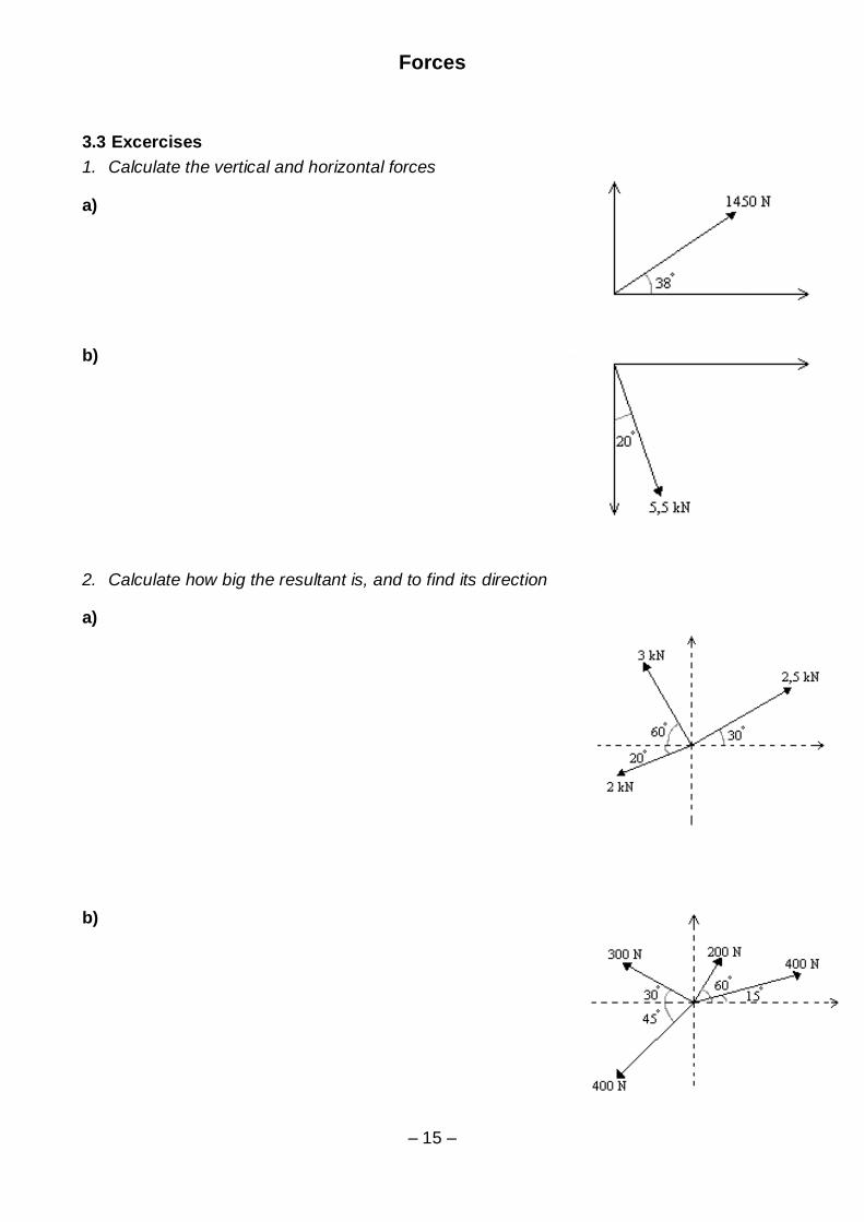
3.3 Excercises
1. Calculate the vertical and horizontal forces
a)
b)
2. Calculate how big the resultant is, and to find its direction
a)
b)

Equilibrium
– 16 –
4 Equilibrium
A force is a push or a pull upon an object which results from its interaction with another object. Forces result from interactions, some forces result from contact interactions
(normal, frictional, tensional, and applied forces are examples of contact forces) and other forces are the result of action-at-a-distance interactions (gravitational, electrical, and magnetic forces). According to Newton, whenever objects A and B interact with each
other, they exert forces upon each other. When you sit in your chair, your body exerts a downward force on the chair and the chair exerts an upward force on your body. There are two forces resulting from this interaction - a force on the chair and a force on your body. These two forces are called action and reaction forces and are the subject of Newton's
third law of motion. Formally stated, Newton's third law is:
Newton's Third Law
For every action, there is an equal and opposite reaction.
Any structure subjected to load, must be provided with supports, to prevent it from moving.
If the structure is in equilibrium (not moving), then the forces from the loads and reactions must be zero in all direction (R=0)
This simply means that a structure with a total downward load of 100 kN must be supported by upward reactions of 100 kN.
4.1 Example:
When a beam press on a column (action), then the column will press at the beam with an equal force, in the opposite direction (reaction).
Condition: ↑ΣV = 0
ΣH = 0 →
4.2 Example:
Determine the forces F1 and F2, when the system is in equilibrium.
↑ΣV = 0: -300 + F1 * sin 300 = 0
NF 60030sin
30001
ΣH = 0: -600 * cos 300 – F2 = 0
→ NF 5202
Control: The triangle is closed → R=0 → equilibrium

Equilibrium
– 17 –
4.3 Example:
Determine the forces F1 and F2, when the system is in equilibrium.
I: ↑ΣV = 0: -500 + F1 * sin 450 – F2 * sin 300 = 0
II: ΣH = 0: -F1 * cos 450 – F2 * cos 300 = 0 →
We have two equations with two unknowns.
We solve equation II to find F1:
– F2 * cos 300 = F1 * cos 450
10
0
2
45cos
30cos*F
F
We put F1 into I:
030sin*45sin*45cos
30cos*500 0
2
0
0
0
2
FF
-0,87F2 – 0,5F2 = 500
-1,366F2 = 500
F2 = -366 N
We put F2 into II:
-F1 * cos 450 – (-366)*cos 300 = 0
NF 44845cos
30cos*3660
0
1

Equilibrium
– 18 –
4.4 Exercises
1. Determine the forces F1 and F2, when the systems are in equilibrium
a)
b)
c)

Moments
– 19 –
5 Moments
A moment means rotations or twisting, and is defined as the product of the force and the
perpendicular distance from the centre of rotation to the line of action.
Moment = force * the perpendicular distance to the line of action
M = F * a
We calculate moments with signs:
Clockwise Anticlockwise
5.1 Example:
The moments depend on the force as well as the perpendicular distance. The units are:
[kNm] [Nm] [Nmm]
Let us look at a beam:
The weight with the mass, m, is placed in the distance a on the left side of the hanging point.
To put the beam in equilibrium we have to place some weight at the right side. On the right side we can:
1. Place a weight with the same mass, m, in the distance a.
2. Place a weight with half of the mass,
m/2, in the distance 2a. 3. Place a weight with the third mass, m/3,
in the distance 3a.
Moments
– 20 –
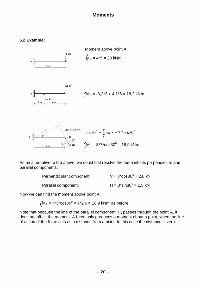
5.2 Example:
Moment above point A:
MA = 4*5 = 20 kNm
MA = -3,2*2 + 4,1*6 = 18,2 kNm
00 30cos*77
30cos xx
MA = 3*7*cos300 = 18,9 kNm
As an alternative to the above, we could first resolve the force into its perpendicular and
parallel components:
Perpendicular component: V = 3*cos300 = 2,6 kN
Parallel component: H = 3*sin300 = 1,5 kN
Now we can find the moment above point A:
MA = 7*3*cos300 = 7*2,6 = 18,9 kNm as before
Note that because the line of the parallel component, H, passes through the point A, it does not affect the moment. A force only produces a moment about a point, when the line
of action of the force acts as a distance from a point. In this case the distance is zero.

Moments
– 21 –
5.3 Two forces or more
If two forces or more affect a solid, then the sum of the forces around any centre of
rotation is equal the moment of the resultant around the same point.
F1 and F2 are displaced along their line of action to
point A, and we find the resultant as usual.
We then have a rule, saying:
R*a = F1 * a1 + F2 * a2 + ………….
The total moment is:
F1 * a1 + F2 * a2 + ………….
5.4 Parallel forces
We will now look at two parallel forces, and we want to replace them with a resultant, witch moment around any centre of rotation, is equal as the moment of the two parallel forces.
We have two parallel forces F1 and F2. The distance between them is “b” and a distance “a” to a random centre of rotation A.
First we calculate the resultant, R:
↓R = F1 + F2
The moment of the forces F1 and F2 around A: M = F1(a+b) + F2 *a
The moment of the resultant R around A: M = R * x
From this you may see: R * x = F1(a+b) + F2 *a
Now you can find x:
R
aFbaFx
*21
Moments
– 22 –
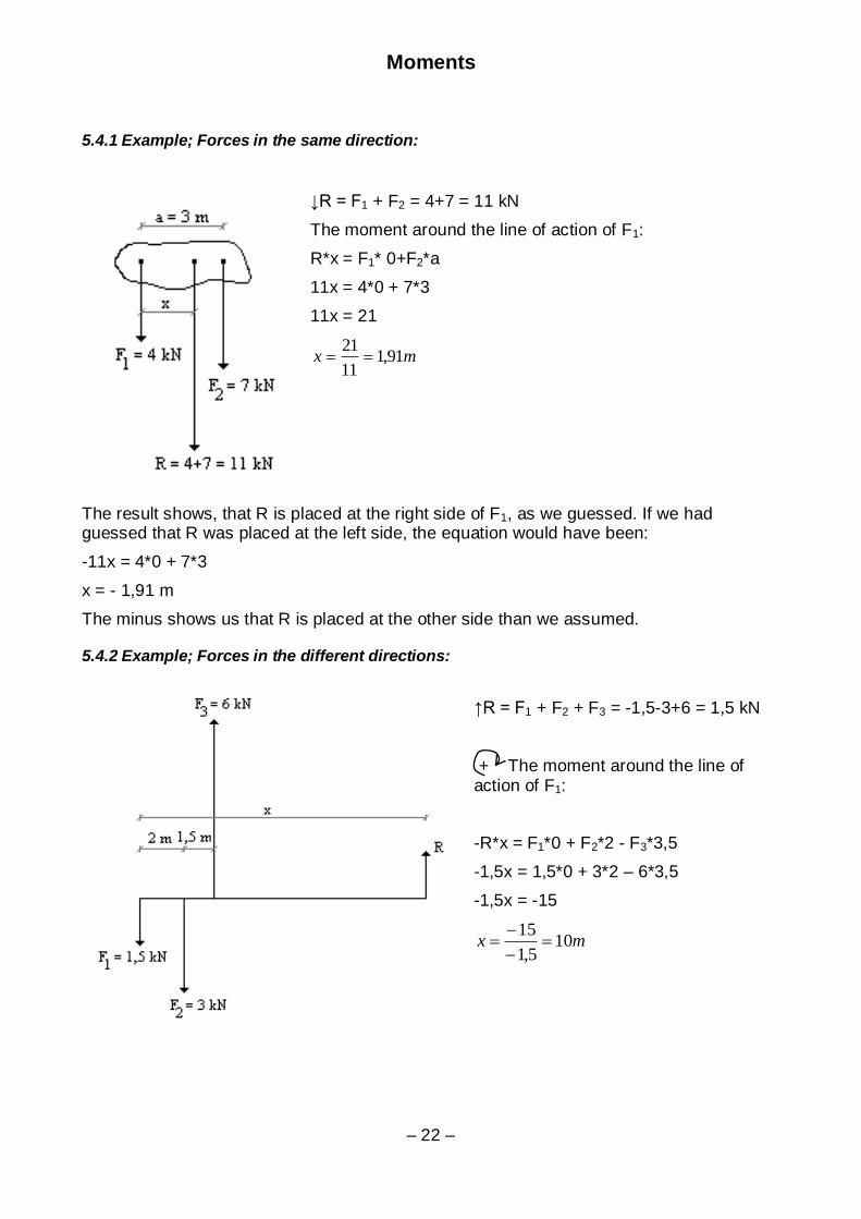
5.4.1 Example; Forces in the same direction:
↓R = F1 + F2 = 4+7 = 11 kN
The moment around the line of action of F1:
R*x = F1* 0+F2*a
11x = 4*0 + 7*3
11x = 21
mx 91,111
21
The result shows, that R is placed at the right side of F1, as we guessed. If we had guessed that R was placed at the left side, the equation would have been:
-11x = 4*0 + 7*3
x = - 1,91 m
The minus shows us that R is placed at the other side than we assumed.
5.4.2 Example; Forces in the different directions:
↑R = F1 + F2 + F3 = -1,5-3+6 = 1,5 kN
+ The moment around the line of action of F1:
-R*x = F1*0 + F2*2 - F3*3,5
-1,5x = 1,5*0 + 3*2 – 6*3,5
-1,5x = -15
mx 105,1
15
Moments
– 23 –
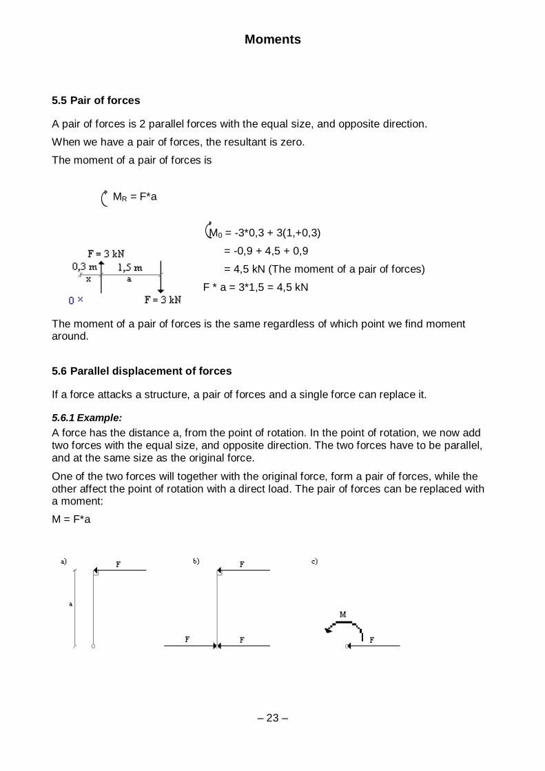
5.5 Pair of forces
A pair of forces is 2 parallel forces with the equal size, and opposite direction.
When we have a pair of forces, the resultant is zero.
The moment of a pair of forces is
MR = F*a
M0 = -3*0,3 + 3(1,+0,3)
= -0,9 + 4,5 + 0,9
= 4,5 kN (The moment of a pair of forces)
F * a = 3*1,5 = 4,5 kN
The moment of a pair of forces is the same regardless of which point we find moment around.
5.6 Parallel displacement of forces
If a force attacks a structure, a pair of forces and a single force can replace it.
5.6.1 Example:
A force has the distance a, from the point of rotation. In the point of rotation, we now add two forces with the equal size, and opposite direction. The two forces have to be parallel, and at the same size as the original force.
One of the two forces will together with the original force, form a pair of forces, while the other affect the point of rotation with a direct load. The pair of forces can be replaced with a moment:
M = F*a
Moments
– 24 –
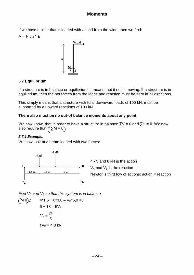
If we have a pillar that is loaded with a load from the wind, then we find:
M = Fwind * a
5.7 Equilibrium
If a structure is in balance or equilibrium, it means that it not is moving. If a structure is in equilibrium, then the net forces from the loads and reaction must be zero in all directions.
This simply means that a structure with total downward loads of 100 kN, must be supported by a upward reactions of 100 kN.
There also must be no out-of balance moments about any point.
We now know, that in order to have a structure in balance ∑V = 0 and ∑H = 0. We now also require that ∑M = 0
5.7.1 Example:
We now look at a beam loaded with two forces:
4 kN and 6 kN is the action
VA and VB is the reaction
Newton’s third low of actions: action = reaction
Find VA and VB so that this system is in balance.
M 0 A: 4*1,5 + 6*3,0 – VB*5,0 =0
6 + 18 = 5VB
5
24BV
↑VB = 4,8 kN

Moments
– 25 –
M=0 B: VA*5,0 – 4*3,5 – 6*2,0 = 0
5VA = 14+12
5
26AV
↑VA = 5,2 kN
Control: ↑∑V = 0: 5,2 + 4,8 – 4 – 6 = 0
10 – 10 = 0 OK!
5.7.2 Example:
Find VA and VB so that this system is in balance.
:0H 6 – HB = 0
HB = 6 kN ←
∑M=0 A: 6 * 2,5 – 4 * VB = 0
4VB = 15
↑VB = 3,75 kN
∑M=0 B: 6 * 2,5 + 4 * VA = 0
4VA = -15
↑VA = -3,75 kN
Control: ↑∑V = 0: -3,75 + 3,75 = 0 OK!

Moments
– 26 –
5.7.3 Example:
Find VA and VB so that this system is in balance.
↑∑V = 0: VA – 2 – 1 = 0
↑VA = 3 kN
:0H -HA + 4 = 0
AH = 4 kN
∑M=0 A: -MA + 2 * 2 + 1 * 4 = 0
MA = 8 kNm
Control:
∑M=0 B: -8 + 3 * 4 – 2 * 2 = 0
-8 + 12 – 4 = 0 OK!
5.7.4 Example:
Find VA and VB so that this system is in balance.
∑M=0 A: - VB*2,0 + 900*2,5 + 1200*3,0 = 0
2,0VB = 5850
↑VB = 2925 kN
∑M=0 B: VA*2,0 + 900*0,5 + 1200*1,0 = 0
2,0VA = -1650
↑VA = -825 kN
Control: ↑∑V = 0: -825 + 2925 – 900 - 1200 = 0
2100 - 2100 = 0 OK!
Comments: The negative values for VA imply that the original direction shown
in the figure is wrong, and the beam must be held down to prevent it from tipping.

Moments
– 27 –
5.8 Exercises
1. Calculate the resultant, and find its direction and position.
a)
b)
2. Calculate the moment of the resultant of the pair of forces
Moments
– 28 –
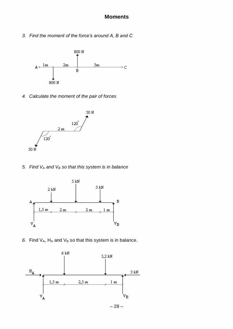
3. Find the moment of the force’s around A, B and C
4. Calculate the moment of the pair of forces
5. Find VA and VB so that this system is in balance
6. Find VA, HA and VB so that this system is in balance.

Supports:
Rev. 16.04.08 – 29 –
6 Supports:
In order to be able to analyse a structure it is necessary to be clear about the forces that can be resisted be each support.
Let us look at the principal types of support and the number of reactive provided by each.
A roller support
A pinned support
A fixed support
A roller support can provide only a single reaction force, which is always perpendicular to this axis of the roller. This means that a single roller support must be provided at some point to prevent the structure to rotate or to move in the horizontal direction.
Roller support must be provided for very long structures, such as a bridge beams, so that
large forces are not produced by thermal expansion and contraction. They can take the form of rubber bearing, which are designed to permit lateral movement.
A pinned support can resist vertical and horizontal forces but not a moment. This means that a pinned support is not sufficient to make a structure stable. Another support must be
provided at some point to prevent the structure to rotate about the pin. A good combination of supports for a structure is therefore a pin plus a roller. Between them they provide enough support to satisfy the three equations of equilibrium.
In practise many structural connections are assumed to be pins, even if specific point of
rotation is not provided. Thus simple bolted connections in a steel frame are often considered to be pinned connections for the purpose of design. In reality a small moment may be resisted, but it is ignored.
A fixed support can resist vertical and horizontal forces as well as a rotational moment.
This means that the structure requires one fixed support to satisfy all three equations of equilibrium. In practise a beam, which is rigidly built-in to a massive concrete wall may be considered to have a fixed support. However, the support must be rigid enough to prevent any rotation if it is to be considered truly fixed.
Supports:
Rev. 16.04.08 – 30 –
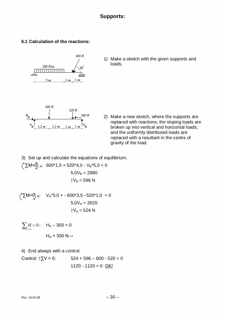
6.1 Calculation of the reactions:
1) Make a sketch with the given supports and loads.
2) Make a new sketch, where the supports are
replaced with reactions, the sloping loads are broken up into vertical and horizontal loads, and the uniformly distributed loads are
replaced with a resultant in the centre of gravity of the load.
3) Set up and calculate the equations of equilibrium.
∑M=0 A: 600*1,5 + 520*4,0 - VB*5,0 = 0
5,0VB = 2980
↑VB = 596 N
∑M=0 B: VA*5,0 + - 600*3,5 –520*1,0 = 0
5,0VA = 2620
↑VA = 524 N
:0H HA – 300 = 0
HA = 300 N→
4) End always with a control.
Control: ↑∑V = 0: 524 + 596 – 600 - 520 = 0
1120 - 1120 = 0 OK!
Supports:
Rev. 16.04.08 – 31 –
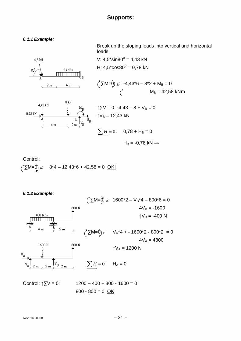
6.1.1 Example:
Break up the sloping loads into vertical and horizontal loads:
V: 4,5*sin800 = 4,43 kN
H: 4,5*cos800 = 0,78 kN
∑M=0 B: -4,43*6 – 8*2 + MB = 0
MB = 42,58 kNm
↑∑V = 0: -4,43 – 8 + VB = 0
↑VB = 12,43 kN
:0H 0,78 + HB = 0
HB = -0,78 kN →
Control:
∑M=0 A: 8*4 – 12,43*6 + 42,58 = 0 OK!
6.1.2 Example:
∑M=0 A: 1600*2 – VB*4 – 800*6 = 0
4VB = -1600
↑VB = -400 N
∑M=0 B: VA*4 + - 1600*2 - 800*2 = 0
4VA = 4800
↑VA = 1200 N
:0H HA = 0
Control: ↑∑V = 0: 1200 – 400 + 800 - 1600 = 0
800 - 800 = 0 OK

Supports:
Rev. 16.04.08 – 32 –
6.2 Exercises
1. Calculate the reactions of this construction:
2. Calculate the reactions of this construction:
3. Calculate the reactions of this construction:
4. Calculate the reactions of this construction:

Supports:
Rev. 16.04.08 – 33 –
5. Calculate the reactions of this construction:
6. Calculate the reactions of this construction:
7. Calculate the reactions of this construction:

Properties of structural materials
– 34 –
7 Properties of structural materials
7.1 Introduction:
In solids, which are not affected by any external forces, the molecules are in a stable
equilibrium position.
If external forces affect the solid, it will be deformed until the internal forces between the
molecules are in equilibrium with the external forces.
If the external forces are removed, the molecules can either stay in the position - plastic
material, or go back to its stable equilibrium position - elastic material.
A plastic material acquires a permanent deformation.
An elastic material will return to its originally form.
7.2 Stress:
We distinguish between external forces such as applied loads, and internal forces, which are produced in structural members as a result of applying loads. Internal forces cause stress:
area
loadStress Or:
A
F MPa
mm
N
²
Stress is a measure of the load on each square millimetre of material and can be thought of as the intensity of internal forces.
7.3 Strain:
Strain is a measure of how much each millimetre length of the material deforms under stress. It is therefore related to the stiffness of the material rather than the strength.
lengthoriginal
extensionStrain
, or:
0L
L
This means that strain is the change in length per unit length. The units of strain are
dimensionless. Because strains are usually small they are often presented as a percentage.
Properties of structural materials
– 35 –
7.4 Modulus of elasticity:
The property, which determines how much strain occurs for a given stress, is the modulus
of elasticity E. This tends to be a constant for a particular material.
Strain
StressE , or:
LA
LFE
*
*
0
0
As the unit of strain are dimensionless, the units of modulus of elasticity are clearly the same as stress i.e. N/mm².
From above: E
StressStrain , or
E
We can see from this that materials with high E values will have relatively small strains and
can be described as stiff.
7.5 Strength and stiffness:
Strength and stiffness are probably the most important of all properties when considering
whether a material is suitable for use in structures. The strength of a material obviously dominates the determination of the collapse load of a structure. Stiffness is vital to ensure that structure do not deflect too much under load. There for stiffness also affects collapse,
as it controls the buckling load of compression members.
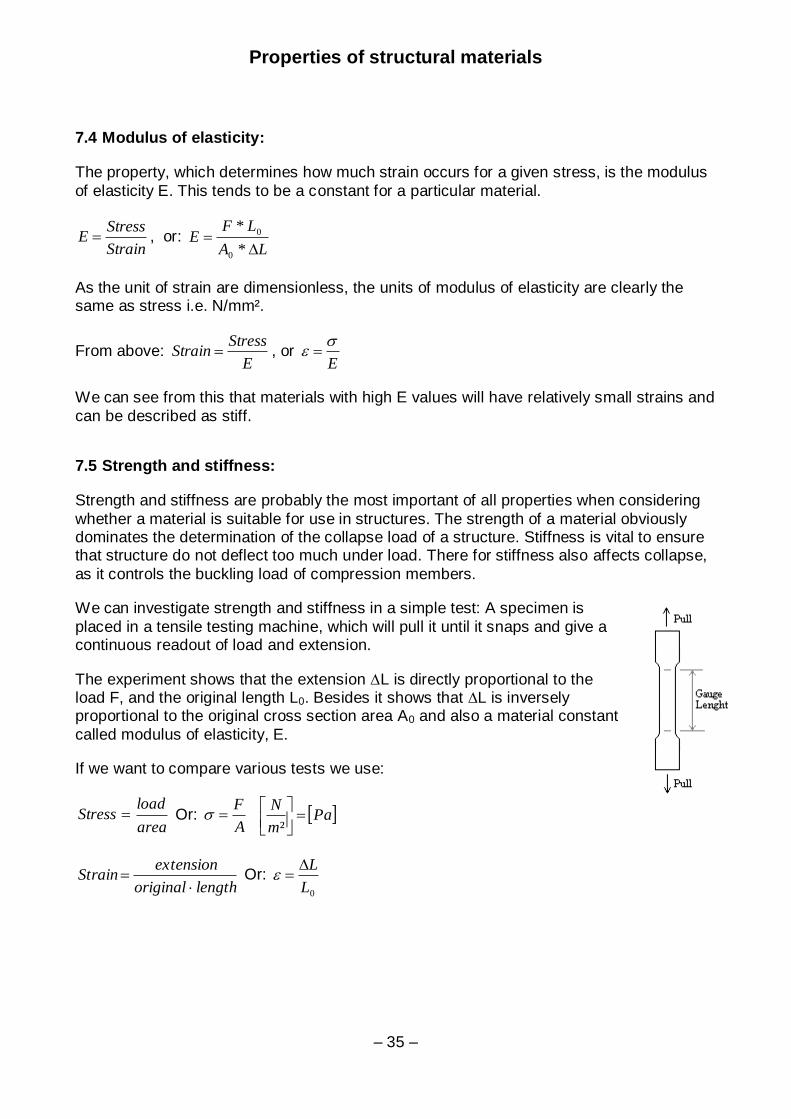
We can investigate strength and stiffness in a simple test: A specimen is
placed in a tensile testing machine, which will pull it until it snaps and give a continuous readout of load and extension.
The experiment shows that the extension ∆L is directly proportional to the load F, and the original length L0. Besides it shows that ∆L is inversely proportional to the original cross section area A0 and also a material constant
called modulus of elasticity, E.
If we want to compare various tests we use:
area
loadStress Or:
A
F Pa
m
N
²
lengthoriginal
extensionStrain
Or:
0L
L
Properties of structural materials
– 36 –
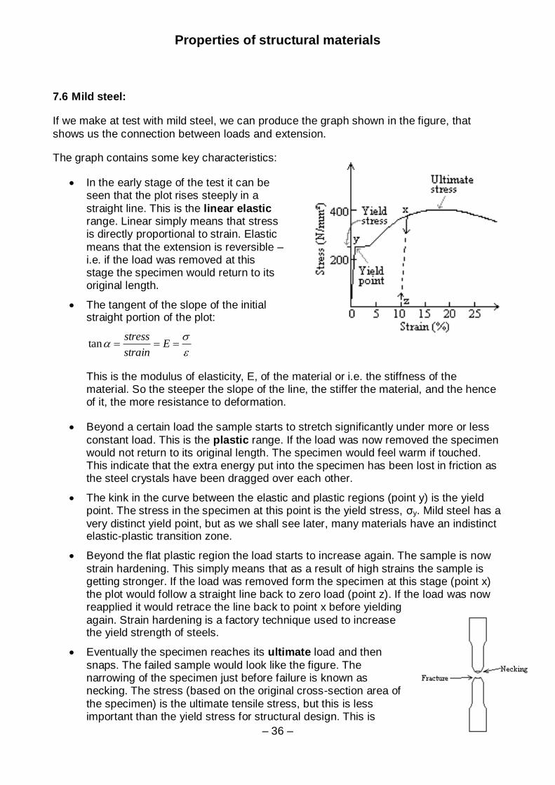
7.6 Mild steel:
If we make at test with mild steel, we can produce the graph shown in the figure, that
shows us the connection between loads and extension.
The graph contains some key characteristics:
In the early stage of the test it can be seen that the plot rises steeply in a
straight line. This is the linear elastic range. Linear simply means that stress is directly proportional to strain. Elastic
means that the extension is reversible – i.e. if the load was removed at this stage the specimen would return to its original length.
The tangent of the slope of the initial straight portion of the plot:
E
strain
stresstan
This is the modulus of elasticity, E, of the material or i.e. the stiffness of the material. So the steeper the slope of the line, the stiffer the material, and the hence of it, the more resistance to deformation.
Beyond a certain load the sample starts to stretch significantly under more or less
constant load. This is the plastic range. If the load was now removed the specimen would not return to its original length. The specimen would feel warm if touched. This indicate that the extra energy put into the specimen has been lost in friction as the steel crystals have been dragged over each other.
The kink in the curve between the elastic and plastic regions (point y) is the yield point. The stress in the specimen at this point is the yield stress, σy. Mild steel has a
very distinct yield point, but as we shall see later, many materials have an indistinct elastic-plastic transition zone.
Beyond the flat plastic region the load starts to increase again. The sample is now
strain hardening. This simply means that as a result of high strains the sample is getting stronger. If the load was removed form the specimen at this stage (point x) the plot would follow a straight line back to zero load (point z). If the load was now reapplied it would retrace the line back to point x before yielding
again. Strain hardening is a factory technique used to increase the yield strength of steels.
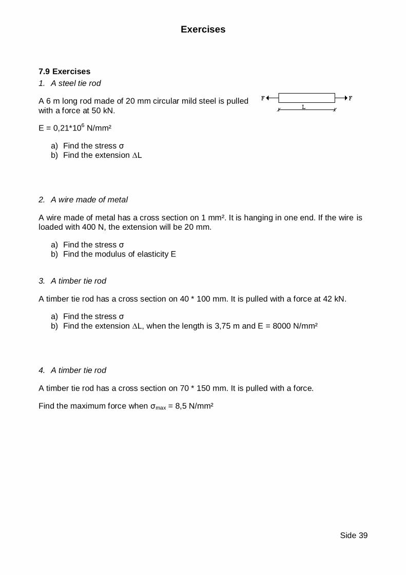
Eventually the specimen reaches its ultimate load and then
snaps. The failed sample would look like the figure. The narrowing of the specimen just before failure is known as necking. The stress (based on the original cross-section area of
the specimen) is the ultimate tensile stress, but this is less important than the yield stress for structural design. This is

Properties of structural materials
– 37 –
because, by the time the ultimate tensile stress is reached, the structure has already suffered unacceptable permanent deformation.
Two other points are worth defining at this stage. The elastic limit is the point beyond which strains are not completely reversible. The limit of proportionality is the point at the end of the straight-line portion of the plot. With mild steel these
points efficiently coincide with the yield point but this is not the case with all materials.
In general structures must be designed so that, throughout their normal working life, stress are always below the yield stress. To go beyond this point would imply that the structure
would suffer large and permanent deformation.
7.7 High yield steel:
The higher grades of steel have much superior strengths, yet the elastic modulus remains
the same. This means that excessive deflection of structures may be more of a problem when using the higher grades.
High yield steel does not have a distinct yield point, and that is why it is necessary to define a proof stress for use in the strength calculations. This is the
stress, which occurs at a given permanent strain – say 0,2%. The figure shows how this is obtained by drawing a line parallel to the linear elastic portion of
the curve.
When the strengths increase the yield point, the end
of the plastic region and the ultimate stress point will grow, but the extension at the ultimate stress point and with that the ductile will fall.

Properties of structural materials
– 38 –
7.8 Timber:
Timbers don’t have a plastic range. This means that when the yield point is reached, the
timber will break.
7.8.1 Example:
A steel tie rod:
F = 35 kN
L = 6 m
A = 201 mm²
The modulus of elasticity: E = 0,21*106
a) Find the extension ∆L
LA
LFE
*
*
0
0
mmEA
LFL 98,4
10*21,0*201
10*6*10*35
*
*6
33
0
0
b) Find the stress σ
²13,174
201
10*35 3
mmN
A
F
Exercises
Side 39
7.9 Exercises
1. A steel tie rod
A 6 m long rod made of 20 mm circular mild steel is pulled
with a force at 50 kN.
E = 0,21*106 N/mm²
a) Find the stress σ b) Find the extension ∆L
2. A wire made of metal
A wire made of metal has a cross section on 1 mm². It is hanging in one end. If the wire is loaded with 400 N, the extension will be 20 mm.
a) Find the stress σ b) Find the modulus of elasticity E
3. A timber tie rod
A timber tie rod has a cross section on 40 * 100 mm. It is pulled with a force at 42 kN.
a) Find the stress σ
b) Find the extension ∆L, when the length is 3,75 m and E = 8000 N/mm²
4. A timber tie rod
A timber tie rod has a cross section on 70 * 150 mm. It is pulled with a force.
Find the maximum force when σmax = 8,5 N/mm²