structural design of a practical suspendome · the frame-shearwall concrete structure is ......
TRANSCRIPT

Advanced Steel Construction Vol. 4, No. 4, pp. 323-340 (2008) 323
STRUCTURAL DESIGN OF A PRACTICAL SUSPENDOME
Zhi-Hong Zhang1,*, Qing-Shuai Cao1, Shi-Lin Dong2 and Xue-Yi Fu 1
1* Ph. D., China Construction (Shenzhen) Design International, NO.138, Kangjian Road, Shanghai, China, 200235
*(Corresponding author: Email: [email protected]) 2 Professor, Space Structure Research Center, Zhejiang University,
Hangzhou, Zhejiang Province, China, 310027
Received: 8 October 2007; Revised: 7 December 2007; Accepted: 10 December 2007 ABSTRACT: Structural design of a practical spherical suspendome with the diameter of 122m was carried out in China Construction (Shenzhen) Design International (CCDI) in 2006. The suspendome structure is a new type of large-span spatial structure which is widely used in the sports buildings. Several suspendome structures have been constructed as the structural roof in the sports arena in China in recent years. As is known to all, prestresses in the cable-strut system are crucial to the tensegric system, and the determination of prestress level and distribution is somewhat complicated. However, no provisions has been provided by current chinese design codes of practice for the suspendome structure. This paper gives out the detailed prestress design procedure for the practical sports arena which is to be built in Jinan City, China. General purpose finite element package ANSYS is utilized for the analyses. The self-internal-force mode and the prestress level ratio among three ring cables are investigated to determine the prestress in the cable. Linear static analyses are then carried out to validate the prestress efficiency. It has been shown that prestress defined by this way has much influence on the deformation and the internal force of the upper reticulated shell structure. The linear elastic buckling and the geometrically nonlinear stability analysis are also presented. The snap-through phenomenon of the structure is investigated to determine the critical load carrying capacity of stability. The infulence of live load distribution patterns and imperfections on suspendome is addressed in details. The results from the studies can not only be refered for direct design use, and also for the design of similar hybrid structures.
Keywords: Space structure, suspendome, tensegric system, prestress, sports building, buckling, eigenmode, geometrically nonlinearity, imperfection
1. INTRODUCTION With the development of the society, more and more novel structures which can cover larger space are needed. Large-span space structures have been put into application at a rapid rate for recent several decades. Based on the demands, several new types of space structure are developed (Liu [1] and Dong et al. [2]): the cable dome structure, the suspendome structure, the beam string structure, etc. Suspendome is a new type of large-span pre-stressed space structure which has only developed for more than one decade. It is a hybrid structure composed of the upper rigid single-layer latticed shell and the lower flexible cable-bar tensile system (Figure 1). Suspendome structure consists of three types of member: the rigid member in the upper single- layer dome, the vertical strut and the cable in the lower tensegric system. Suspendome can be derived from two types of structure: 1) It is formed by replacing the upper cables of the cable dome by the rigid members, usually the single-layer latticed dome. Compared with the cable dome, prestress in the suspendome can be observably reduced. As the upper rigid members can provide certain initial stiffness to the structure, form finding analyses is no longer necessary and the construction techniques are simplified. The upper rigid member can resist both the axial force and the bending moments to increase the rigidity of the structure in one hand, and in the other hand the stress/force flow in suspendome may be closed, thus make the structure a self-equilibrium system, and weak bearing system is possible(Zhang [3], Zhang [4]). 2) The upper single-layer latticed dome is strengthened by the lower tensegric system. This method reasonably enhances the stiffness of the latticed shell and improves the buckling capacity. As the bearing horizontal reaction induced by the

324 Structural Design of a Practical Suspendome
service load is reverse to that induced by the tensegric system, the bearing horizontal reaction can be reduced to zero if proper prestress in the cables are introduced. The maximum value of axial force in the upper single-layer dome members can also be reduced by the tensegric system (Zhang [3], Zhang [4], Kang et al. [5], Kitipornchai [6]). So suspendome is also called “hybrid space structure”.
Figure 1. Suspendome: the Latticed Shell and the Cable-Strut System
Figure 2. Zero State and Initial State of Suspendome The suspendome design procedure is a little complicated. On the basis of the construction procedure of the suspendome, three typical reference configurations are defined (shown in Figure 2): 1) the zero state geometry, is the equilibrium state without prestress and without self-weight in the structure to determine the lofting during construction. 2) the initial state geometry, is the equilibrium state with prestress in the structure and under self weight after cambering, corresponding to the constructed configuration of the structure. 3) the loading state geometry, is the equilibrium state after loaded. The structural deformation in this paper is based on the initial state as the reference configuration, and the initial stresses in the members of the upper single layer dome are also taken into consideration. Analytical and experimental research on the structural behavior of suspendomes has been performed in various approaches by the researchers (Zhang [3], Zhang [4,7], Kang et al. [5], Kitipornchai [6]). Based on Equilibrium Matrix Theory (Calladine and Pellegrino [8,9,10,11]), a new method called “local analyses method” to determine the structural self-internal-force mode is put forward (Zhang [3], Zhang [4,7]). The lower tensegric system is detached from the upper single layer dome as an independent system. Boundary restraints are applied to the lower independent tensegric system to determine the self-internal-force modes. The initial prestress distribution of the tensegric system can be obtained by the superposition of self-internal-force modes. The interaction of the lower tensegric system to the upper single layer dome is applied as the equivalent load to obtain the initial stress distribution of upper single-layer dome (the initial state, showed in Figure 2.). For detailed information, please refer to Reference [3].
+ =
zero state initial state
prestress

Zhi-Hong Zhang, Qing-Shuai Cao, Shi-Lin Dong and Xue-Yi Fu 325
Figure 3. Airscape of Jinan Olympic Sports Center-the Gymnasium (China, 2009)
Several suspendome structures have been constructed in China in recent years (Liu [1] and Dong et al. [2]). However, no provisions has been provided by the current chinese design codes of practice for suspendome. The design method for the above mentioned constructed suspendome seems discretionary and unorganized. This paper gives out the detailed design procedure for the practical sports arena which is to be built in Jinan City, China, at the preliminary design stage (shown in Figure 3). 2. THE DESIGN MODEL 2.1 General Information of the Arena Jinan Olympic Sports Center-the Gymnasium is a multi-purpose building and located in Jinan City, China. The facility will serve as the center-piece of the local Olympic Games held in the city in 2009. The building is in the shape of the ellipse with the longitudinal length 220 meters and the latitudinal length 168 meters (Figure 3). Two adjacent accessorial gymnastic building for warming up before the event are designed in the two ends of the Gymnasium. The building has an approximate architectural area 60,000 m2 which is to accommodate more than 12,000 audiences. The architectural style of the roof exposits full-bodied regional characteristics- the lotus flower and the willow leaf (Figure 3). Suspendome structure is chosen as the roof of the gymnasium. The span and the rise of the dome are 122.0m and 12.2m respectively, making the rise to span ratio 1/10. The Sunflower-Kiewitt patterned hybrid single-layer dome is used in the upper part of the roof structure. The roof is covered with the rigid profiled steel sheet. Three rings of cable-strut are arranged in the suspendome (Figure 4 and Figure 8). The suspendome consists of 1230 pipe members, 379 nodes, and 48 spherical steel bearings. The frame-shearwall concrete structure is used in the lower part of the building. The roof bearing joints is supported by alternate columns and the ring beam.

326 Structural Design of a Practical Suspendome
Figure 4. The Suspendome Structure for the Design 2.2 Finite Element Model All analyses are carried out using the commercial general purpose finite element package ANSYS. The 3-D quadratic beam element BEAM188 which has three displacement and three rotational degrees-of-freedom (DOFs) is used to discretize the members in the upper dome and the spar element LINK10 with the tension-only (or compression-only) option which has three displacement degrees-of-freedom (DOFs) is used to model the cables and the struts. The material Q345B (GB50017-2003 [12]) is used in the members of upper single layer dome and the vertical struts which have properties typical of steel: an elastic modulus E of 2.06x10⁵ N/mm2, a Poisson’s ratio of 0.3 and a designed strength f of 310N/mm2. The cables are made of high-strength seven-steel-wires which have an elastic modulus E of 1.90x10⁵ N/mm2, a Poisson’s ratio of 0.3 and the ultimate tensile capacity 1670 N/mm2 (Shen et al. [13]). Both types of the material have the mass density of 7850kg/m3, and the thermal expansion coefficient of 1.2x10⁻⁵/oC. Each finite element node has six degrees of freedom including translations in the x, y, and z directions and rotations about the x, y, and z directions. Welded gapless steel pipes with the diameter 351mm and the thickness from 12mm, 14mm to 16mm are used in the upper single-layer dome. The chord member and the bracing member are connected each other to form the intersecting joint (GB50017-2003 [12]). As the bracing members are welded directly with the chord members, the connections are modeled as the rigid joints. The upper steel roof is supported by the lower concrete structure with the spherical steel bearings. Regarding the boundary conditions to the roof model, the connections are treated as hinged joints, i.e, all translational degrees of freedom (DOFs) are peripherally fixed at the bottom of the structure (Ux, Uy, Uz). The finite element model is shown in Figure 5.
a) Top view b) Side view
3rd ring 2nd ring
1st ring

Zhi-Hong Zhang, Qing-Shuai Cao, Shi-Lin Dong and Xue-Yi Fu 327
Figure 5. Finite Element Model of the Suspendome
3. DETERMINATION OF THE SELF-INTERNAL-FORCE MODE This section determines the self-internal-force mode of the tensegric system based on the “local analysis method” (Zhang [3]). In the lower tensegric system, the cables and the vertical struts are hinged in the joints. The cables are tension-only elements and the vertical struts are compression-only elements. Nodal force equilibrium at each joint can be expressed in the x, y, and z directions. The equilibrium equation of the lower cable-bar system is shown in Eq. 1 as follows. [ ]{ } { }A t p= (1)
in which, [ ]A is the equilibrium matrix of the system-the function of nodal coordinates,
{ }t is the internal force vector of the elements,
{ }p is the equivalent force vector at the nodes. Typical unit of the lower tensegric system is shown in Figure 6. By Singular Value Decomposition of the equilibrium matrix [ ]A (Calladine and Pellegrino [8,10,11]), the number of the self-internal-force mode s can be obtained as s=3. Figure 7 shows the axial force equilibrium in node i, where, hciN is the axial force in the horizontal (hoop) cable; dciN is the axial force in the diagonal (radial) cable; vbiN is the axial force in the vertical strut, iα is the angle between the horizontal hoop cables and iβ is the angle between the diagonal cable and the vertical strut.
Figure 6. Typical Unit of the LowerTensegric System Note: DC, the diagonal cable; HC, the hoop cable; VB, the vertical strut.
1,2,3 refers to the first (outmost), second (middle) and third (innermost) ring of the tensegric system respectively.
DC1
DC2
DC3
HC1
HC2
HC3 VB1
VB2
VB3

328 Structural Design of a Practical Suspendome
Figure 7. Axial Force Equilibrium in Typical Node i.
According to the force equilibrium in the vertical and the hoop direction, the equilibrium equation in node i can be expressed as:
( )cosvbi dci iN N β= − (2)
( ) ( )2 cos 2dci i hci iN sin Nβ α= (3) Combining Eq. 2 and Eq. 3, the following equations can be obtained:
( )( )
2cos 2idci hci
i
N Nsin
αβ
= (4)
( )( )
2cos 2tan
ivbi hci
i
N Nαβ
= − (5)
Giving 1hciN = , the self-internal-force mode in the ith ring of the tensegric system is:
[ ], ,hci dci vbiN N N =( )( )
( )( )
2cos 2 2cos 21, ,
sin tani i
i i
α αβ β
⎡ ⎤−⎢ ⎥
⎣ ⎦ (6)
Three hoop rings altogether are designed in the structure (shown in Figure 4, 5, 6 and 8.). The angle
iα (i=1,2,3) in this model is 165o, and iβ is 80o, 75o, 72o respectively for i=1,2,3. The self-internal-force modes of the lower cable-strut system for the outer, middle and inner ring are as follows: [ ] [ ]1 2 3t , t , t Tt = (7)
where, { } [ ]1 1.0, 0.2651, -0.0460 Tt =
{ } [ ]2 1.0, 0.2703, -0.0699 Tt =
{ } [ ]3 1.0, 0.2745, -0.0848 Tt =
iαiβ
hciN
hciN
dciN
vbiN
i

Zhi-Hong Zhang, Qing-Shuai Cao, Shi-Lin Dong and Xue-Yi Fu 329
4. DETERMINATION OF CABLE PRESTRESS RATIO AMONG THREE HOOPS OF THE CABLE-STRUT SYSTEM
The number of rings in the tensegric system and the prestress level ratio among the rings have much infulence on the structural behavior, therein, the outmost ring with prestress is the most effective (Zhang [3], Kang et al. [5]). As is mentioned above, steel pipes with diameter 351mm and thichness from 12, 14 to 16mm are used in the upper single-layer dome. The member arrangements of the upper single-layer dome are shown in Figure 8. Characteristic combined load between uniformly distributed dead load 0.8kN/m2, and uniformly distributed live load 0.3kN/m2 is applied to the roof as the service load (GB50009-2001 [14]). Each nodal external concentrated force is determined by the product of the combined load and its tributary area. The nodal tributary area is calculated by self-developed program. Linear static analysis is then carried out. As the three rings of cable-strut of the tensegric system are assumed to be independent of each other. The actions of each ring are applied separately to the upper single layer dome as the equivalent load. The prestressed force hciN in each ring is assumed provisionally to be 0 1000T kN= , when the dome is only stiffened by the single ring. The displacements of the upper single layer dome under dead and live load and each ring equivalent loads are listed in Table 1 together with the horizontal radial reaction of the bearing joint for the typical nodes defined in Figure 8.
Figure 8 Member Arrangements for Upper Single Layer Dome and Typical Node and Element Numbers
Table 1. Vertical Displacements and Horizontal Radial Reactions for Three Rings of EL
Node Vertical Displacement (mm)
Node 9 Node 6 Node 4
Joint Horizontal Radial Reaction in
Node 13 (kN) Dead +Live Load -30.7160 -31.6642 -28.8879 1030.3
1st Ring EL 9.7831 -2.1155 -2.9381 -325.55 2nd Ring EL -32.6276 40.3484 19.1530 8.85 3rd Ring EL -1.9012 -42.6057 58.7856 -0.68
Note: EL, the equivalent load.
Φ351x14Φ351x16
strut Φ351x12

330 Structural Design of a Practical Suspendome
Relationship between the service load and three-ring equivalent loads is established to determine the prestressed force ratio among three rings of cable-strut system. The vertical displacement of the typical Node 4, 6 and 9 (the nodes at the top of the vertical struts) is considered to be zero under the dead and live load and the three rings of equivalent loads. So the relation can be expressed as: [ ]{ } { }B bϕ = (8)
where, [ ]9.7831 32.6276 1.90122.1155 40.3484 42.60572.9381 19.1530 58.7856
B− −⎡ ⎤
⎢ ⎥= − −⎢ ⎥⎢ ⎥−⎣ ⎦
{ } [ ]30.7160,31.6642,28.8879 Tb =
Solving the above equation, { }ϕ can be obtained:
{ } [ ]8.7290, 1.6532, 0.3891 Tϕ = (9) From the above results, the prestress force ratio for the outmost ring has the largest value and consequently is the most effective. The prestress force (unit: kN) in the tensegric system can then be noted as:
[ ] { } [ ]
0 2
3
HC DC VB18729.0 2314.1 -401.5
1653.2 4468.6 -115.6389.1 1068.1 -33.0
Ring
nd Ring
rd Ring
stT T diag tϕ
⎡ ⎤⎢ ⎥= =⎡ ⎤⎣ ⎦ ⎢ ⎥⎢ ⎥⎣ ⎦
(10)
in which, [ ] [ ]1 2 3, , Tt t t t= , refers to Eq. 7,
{ }8.7290
1.65320.3891
diag ϕ⎡ ⎤⎢ ⎥=⎡ ⎤⎣ ⎦ ⎢ ⎥⎢ ⎥⎣ ⎦
The joint horizontal radial reaction under three-ring equivalent load is Re= -2827.36kN, it is opposite to and much greater than the reaction Rs=1030.3kN induced by the service load. If full-scale prestress force is introduced to the cables, the reaction of bearing joint would be as large as 1800kN or so. This also adds difficulty for the design of the bearings and the prestress needs a second order optimization. For the wind load case, the reaction induced in the same bearing joint may be reversed for the case of randomicity of the wind. The joint horizontal radial reaction under wind load is 519.12wR = ± kN. Assume that the prestress ratio among three rings keeps unchanged, a reduction factor γ is proposed to reduce the prestress level in the cable-strut system. The following equation is used to determine the reduction factorγ :
0.5 ( )e s wR R abs Rγ + = (11) where, , ,e s wR R R is the joint horizontal radial reaction under three-ring equivalent load, the service load and the wind load respectively, and abs(Rw) is the absolute value of the bearing reaction under wind load. Substituting the value to Eq. 11, γ can be obtained: 0.2726γ = . The optimized prestress force (unit: kN) for the tensegric system is determined as follows:
[ ]
2
3
HC DC VB12379.5 630.8 -109.5
450.7 121.8 -31.5106.1 29.1 -9.0
Ring
nd Ring
rd Ring
stT
⎡ ⎤⎢ ⎥= ⎢ ⎥⎢ ⎥⎣ ⎦
(12)

Zhi-Hong Zhang, Qing-Shuai Cao, Shi-Lin Dong and Xue-Yi Fu 331
The cables and struts are designed by the prestress forces obtained by Eq. 12. The geometric parameters and the designed prestress forces of the lower cable-strut system is shown in Table 2. As the compressive elements, the lateral stability of the vertical struts should be verified. The Euler critical buckling capacity of the struts in the three rings is -341kN, -204kN and -93.1kN respectively by the equation ( )22
crN EI lπ μ= (GB50017-2003 [12]), where, crN is the Euler
critical buckling force, E is the material elastic modulus, 4 64I dπ= is the inertia moment of the section, d is the strut diameter, μ is the coefficient of effective length and μ =1, l is the geometric length of the vertical strut. Hence, the struts buckling capacity is satisfied.
Table 2. Prestresses and Geometries of the Lower Tensegric System 1st Ring 2nd Ring 3rd Ring HC1 DC1 VB1 HC2 DC2 VB2 HC3 DC3 VB3
Section 2Φ7x85 Φ7x55 Φ203x6 Φ7x31 Φ7x13 Φ152x4.5 Φ7x7 Φ7x7 Φ95x3.5Area (mm2) 6542 2117 3826 1193 500 2147 269 269 1045
Inertia Moment(m4) - - 1.80e-5 - - 5.86e-6 - - 1.05e-6
Length (m) 10.772 20.043 10.217 6.780 15.830 7.416 4.080 10.875 4.728 Initial strain
(με) 1914.4 1568.2 -139.0 1988.2 1282.1 -71.21 2075.0 569.56 -41.79
Prestress Force (kN) 2379.5 630.8 -109.5 450.7 121.8 -31.5 106.1 29.1 -9.0
5. STATIC ANALYSES This section presents the results of linear static response of suspendome and single-layer dome (SLD) under service load to validate the efficiency of the designed prestresses (prestress stiffening effect is considered). Based on the linear superposition theory, the structural displacement at the top of the strut is zero under combined dead and live load with the full-scale three-ring prestress. The deformation for non-optimal prestress suspendome under service loads is shown in Figure 9. The maximum vertical displacement occurs between the bearing joint and the outmost ring (Node 11, Figure 8), and the value is only 34.23mm. The deformation for the optimized prestress suspendome under service loads is shown in Figure 10. The maximum vertical displacement occurs between the outmost ring and the middle ring (Node 7, Figure 8), and the value is only 26.42mm.
Figure 9. Deformation of Suspendome under the Service Load
( 1.0γ = ,scaled by a factor of 100)

332 Structural Design of a Practical Suspendome
The vertical displacement for the typical numbered nodes (as defined in Figure 8) of the single-layer dome and the suspendome under service load is shown in Figure 11. The vertical displacement of the single-layer dome is larger than that of the suspendome. The single layer dome has the largest downward displacement and occurs at Node 7. The non-optimized prestress suspendome has the smallest downward displacement and occurs at Node 9. The deformation seems uneven and fluctuates greatly up and down in the vertical direction for the unreasonable tensegric prestress distribution and even upward displacement in Node 5 is induced. This reveals the fact that the outmost ring of the tensegric system has the most effects on the suspendome structure, and the other two rings has relatively low effects on the structure. After prestress optimization, the deformation becomes uniform, and the largest downward displacement is 26.42mm, corresponding to the ratio of the deflection to the span 1/4618. The displacement of the optimized tensegric system greatly satisfies the structural allowable deflection specifications L/400 (L is the dome span) (GB JGJ61-2003 [15])and the architectural design.
Figure 10. Deformation of Suspendome under the Service Load ( 0.2726γ = , scaled by a factor of 100)
-40-35-30-25-20-15-10-505
1 2 3 4 5 6 7 8 9 10 11 12 13Node number
Ver
tical
def
lect
ion(
mm
SLDγ=1.0γ=0.27
Figure 11. Vertical Displacement of Typical Numbered Nodes under Service Load

Zhi-Hong Zhang, Qing-Shuai Cao, Shi-Lin Dong and Xue-Yi Fu 333
Normally, tensile axial forces in the members of the upper suspendome are induced by the lower tensegrity system. It is incompatible with the compressive axial force induced by the service load. So proper prestress introduced in lower tensegric system will greatly counteract the effects caused by the service load. The horizontal radial reactions are 320.8kN in the optimized suspendome and 963.5kN in the single layer dome under service load. The maximum axial forces are 469.3kN, 496.6kN, 545.8kN in the optimized suspendome and 498.2kN, 483.5kN, 645kN in the single-layer dome under the same service load for pipe section Φ351x12, Φ351x14, Φ351x16 respectively. It shows that not only the bearing reactions but also the pipe member axial force of the suspendome can decrease greatly compared to the single-layer dome under the same service load. The axial force for the typical numbered radial members (as defined in Figure 8) of the single- layer dome and the suspendome under service load is shown in Figure 12. The axial force of the single-layer dome is larger than that of the suspendome. The axial force in the non-optimized prestress suspendome is greatly uneven in the radial direction for the unreasonable tensegric prestress distribution. The axial force in Member 9 (connected with the first ring, as stated in Figure 8) is near to zero. This suggests again that the outmost ring of the tensegric system has the most effects on the static property of the suspendome structure. The axial forces in the optimized suspendome are very even, and it is favorable for the member design.
-700
-600
-500
-400
-300
-200
-100
01 2 3 4 5 6 7 8 9 10 11 12
Element number
Axi
al fo
rce
(kN
)
SLDγ=1.0γ=0.27
Figure 12. Radial Axial Force of Typical Numbered Elements under Service Load
Figure 13 shows the axial force for the typical numbered hoop members (as defined in Figure 8) of the single layer dome and the suspendome under service load. The characteristics of the axial forces distribution are very similar to that shown in Figure 12. The axial forces in the optimized suspendome are very even, and is also favorable for the member design. It is noteworthy that the stress ratio (the ratio of the peak sectional stress of the members to the material design strength f ) of the elements in the dome under service load is usually comparatively small ranging from 0.1 to 0.5, thereby the material strength is unlikely to govern the structural design. From the above analyses, it can be concluded that the optimized prestress defined by Equation 12 is harmonious with both the axial force and the deformation of the structure. The optimized prestress level is used for all analyses below.

334 Structural Design of a Practical Suspendome
-800-700-600-500-400-300-200-100
013 14 15 16 17 18 19 20 21 22 23 24
Element number
Axi
al fo
rce
(kN
)
SLDγ=1.0γ=0.27
Figure 13. Hoop Axial Force of Typical Numbered Elements under Service Load
6. LINEAR ELASTIC BUCKLING ANALYSES Buckling analysis, in general, may be divided into linear elastic buckling (bifurcation) and geometrically nonlinear buckling (snap-through) analysis. Geometrically nonlinear analyses are usually used to determine the limit load of the structure which are usually started with a linear buckling analysis. Linear buckling analysis predicts the theoretical buckling strength (the bifurcation point) of an ideal linear elastic structure. The results are buckling modes and load factors (eigenvalue). Load factors are estimated for an upper limit of the ultimate load. The buckling modes are related to a structure that maintains its shape up to buckling. If the load applied to the structure is P, the critical buckling load is Pλ . The equation of bifurcation buckling is expressed as an eigenvalue problem: [ ] [ ]( ){ } 0i iK Sλ ψ+ = (13)
where: [ ]K is the stiffness matrix of the system,
[ ]S is the stress stiffness matrix,
iλ is a load factor , the ith eigenvalue determining buckling load,
{ }iψ is the ith eigenvector determining the buckling mode.
This section presents the linear buckling of suspendome using a linearized model of elastic stability. Two load cases are considered for this section and the below: Load Case 1, the dead load combing the full-span live load (LC1); Load Case 2, the dead load combing the half-span live load (LC2). Half-span live load such as the snow load and the construction load is proved to decrease the structural load-carrying capacity in most circumstances and often neglected by the structural designer. The eigenvalues are listed in Table 3, which shows that the buckling capacity of the suspendome is very high and the capacity for LC1 is higher than that for LC2 for the influence of the unsymmetrical distribution of the live load. The lowest bifurcation eigenvalue amounts to 12.13 for LC1 and to 10.86 for LC2 respectively. The buckling capacity decreases by 10.47% for the influence of the unsymmetrical live load..

Zhi-Hong Zhang, Qing-Shuai Cao, Shi-Lin Dong and Xue-Yi Fu 335
Table 3. Eigenvalues of Suspendome for LC1 and LC2
n 1 2 3 4 5 6 7 8 9 10 LC1 12.13 12.13 13.02 13.04 13.04 13.16 13.17 13.48 13.48 13.54 LC2 10.86 10.96 11.25 11.27 11.29 11.48 11.66 11.67 11.89 11.95
a) 1st mode b) 2nd mode c) 3rd mode
d) 4th mode e) 5th mode f) 6th mode
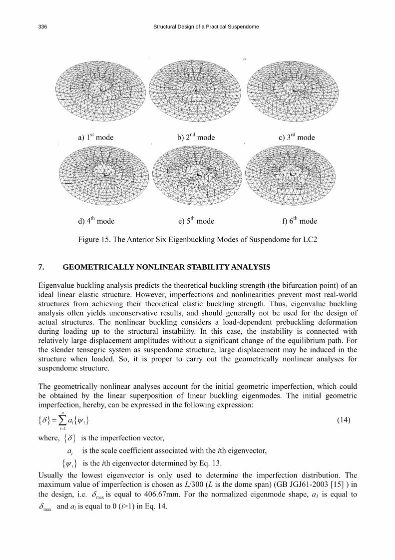
Figure 14. The Anterior Six Eigenbuckling Modes of Suspendome for LC1 Figure 14. and Figure 15. show the anterior six eigenbuckling modes of suspendome LC1 and LC2. The eigenvalues are very close and the buckling modes are very dense for the two cases for the influence of the cable-strut prestresses. The buckling modes are usually in symmetrical shape for structure for LC1 and unsymmetrical shape for LC2. It can also be observed from the figures that the buckling region of the suspendome for LC1 is more localized in the center and buckling usually begin with great deformation in the central area. This phenomenon can be established by the fact that the central area of the dome with a diameter about 30 meters is single-layered within the third ring of cable-strut system, thus makes actually a secondary single-layer latticed dome which is unstiffened by the lower tensegric system. Since the suspendome is mainly stiffened by the outmost ring of the tensegric system, the local weaker stiffness detected in the structural center is reasonable and expected. For LC2, the most localized deformation is usually in the area adjacent to the strcutual boundary for the influence of the unsymmetrical live load. As the increase of the buckling number n, the buckling region becomes extended to the structural boundary. The buckling deformation induces more fluctuations on the surface, and consequently shifts to the global buckling mode.
336 Structural Design of a Practical Suspendome
a) 1st mode b) 2nd mode c) 3rd mode
d) 4th mode e) 5th mode f) 6th mode
Figure 15. The Anterior Six Eigenbuckling Modes of Suspendome for LC2
7. GEOMETRICALLY NONLINEAR STABILITY ANALYSIS Eigenvalue buckling analysis predicts the theoretical buckling strength (the bifurcation point) of an ideal linear elastic structure. However, imperfections and nonlinearities prevent most real-world structures from achieving their theoretical elastic buckling strength. Thus, eigenvalue buckling analysis often yields unconservative results, and should generally not be used for the design of actual structures. The nonlinear buckling considers a load-dependent prebuckling deformation during loading up to the structural instability. In this case, the instability is connected with relatively large displacement amplitudes without a significant change of the equilibrium path. For the slender tensegric system as suspendome structure, large displacement may be induced in the structure when loaded. So, it is proper to carry out the geometrically nonlinear analyses for suspendome structure. The geometrically nonlinear analyses account for the initial geometric imperfection, which could be obtained by the linear superposition of linear buckling eigenmodes. The initial geometric imperfection, hereby, can be expressed in the following expression:
{ } { }1
n
i ii
aδ ψ=
=∑ (14)
where, { }δ is the imperfection vector,
ia is the scale coefficient associated with the ith eigenvector, { }iψ is the ith eigenvector determined by Eq. 13.
Usually the lowest eigenvector is only used to determine the imperfection distribution. The maximum value of imperfection is chosen as L/300 (L is the dome span) (GB JGJ61-2003 [15] ) in the design, i.e. maxδ is equal to 406.67mm. For the normalized eigenmode shape, a1 is equal to
maxδ and ai is equal to 0 (i>1) in Eq. 14.
Zhi-Hong Zhang, Qing-Shuai Cao, Shi-Lin Dong and Xue-Yi Fu 337
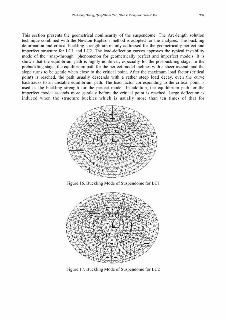
This section presents the geometrical nonlinearity of the suspendome. The Arc-length solution technique combined with the Newton-Raphson method is adopted for the analyses. The buckling deformation and critical buckling strength are mainly addressed for the geometrically perfect and imperfect structure for LC1 and LC2. The load-deflection curves approves the typical instability mode of the “snap-through” phenomenon for geometrically perfect and imperfect models. It is shown that the equilibrium path is highly nonlinear, especially for the postbuckling stage. In the prebuckling stage, the equilibrium path for the perfect model inclines with a sheer ascend, and the slope turns to be gentle when close to the critical point. After the maximum load factor (critical point) is reached, the path usually descends with a rather steep load decay, even the curve backtracks to an unstable equilibrium path. The load factor corresponding to the critical point is used as the buckling strength for the perfect model. In addition, the equilibrium path for the imperfect model ascends more gentlely before the critical point is reached. Large deflection is induced when the structure buckles which is usually more than ten times of that for
Figure 16. Buckling Mode of Suspendome for LC1
Figure 17. Buckling Mode of Suspendome for LC2

338 Structural Design of a Practical Suspendome
Figure 18. Buckling Mode of Suspendome for LC1 with L/300 Imperfection
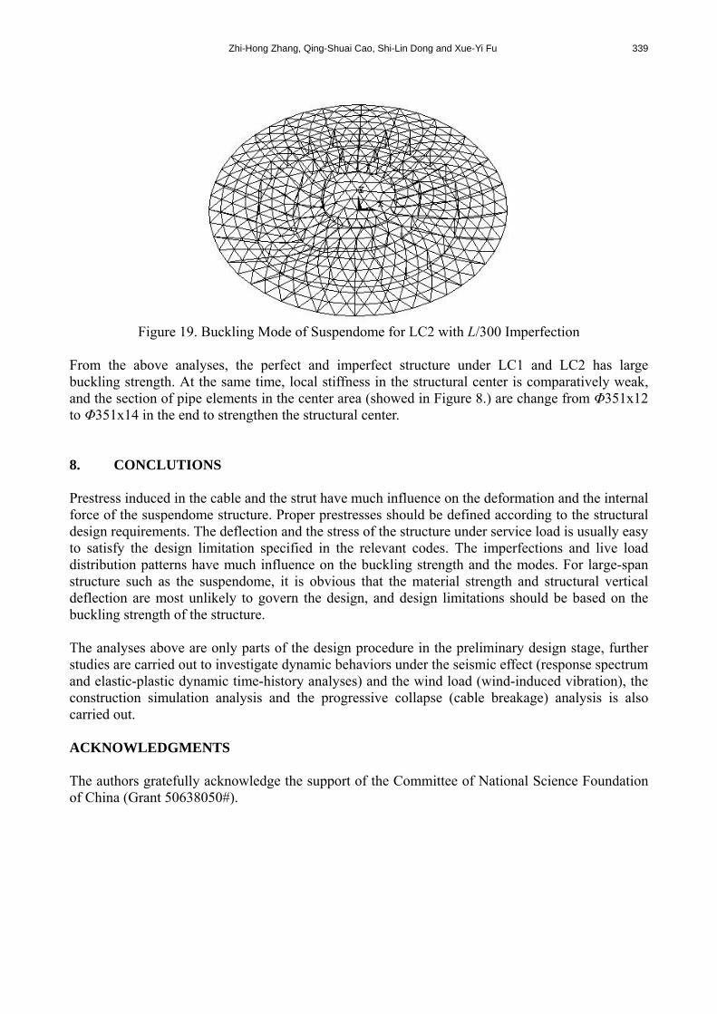
the perfect model, and is unlikely to satisfy the deflection limitations. In the equilibrium path, no maximum load factor is reached in the range of deflection specifications which should not be more L/400 (GB JGJ61-2003 [15] ). The load factor corresponding to the vertical deflection with the magnitude of L/400 is specified as the buckling strength for the imperfect model. After the structure reachs its critical point, the equilibrium paths usually tend to increase in a plateau and the structure possess good postbuckling strength retention capability. The global stiffness of the structure tend to degenerate to naught. This seems to be a clear sign of instability of the structure and the failure may be a sudden phenomenon. The postbuckling is so complicated that the equilibrium path is difficult to trace down. The maximum load factors are 9.91 and 8.89 for the geometrically perfect model, and 5.22 and 4.59 for the geometrically imperfect model for LC1 and LC2 respectively. The structrual limit load decrease by 10.29% of perfect model and 12.07% of imperfect model for the influence of unsymmetrical distribution of the live load. The influence of imperfection is even more destructive to the structure. The limit load decrease by 47.33% for LC1 and 48.37% for LC2. The buckling modes are shown in Figure 16-19 for the geometrically perfect and imperfect structure for LC1 and LC2 respectively. The deformations for perfect models for LC1 are symmetrical global buckling modes and unsymmetrical global modes for LC2. The most vertical displacement for LC1 occurs in the structrual center (Node 1, Figure 8). The deformation for LC2 is more localized (Node 11, Figure 8) in the area to which the half-span live load is applied. The structural center (Node 1, Figure 8) only deflects a small vertical displacement. The most vertical displacement occurs in the areas between the outmost ring and the boundary for the two cases, and this show little agreement with the results from the bifurcation analyses. The deformations for imperfect models for LC1 and LC2 are both unsymmetrical local buckling modes. As it is well known, large span structures are most sensitive against imperfections. From the bifurcation analyses, the eigen modes are loalized in the center for LC1 and adjacent to the boundary for LC2. As the introduction of the eigen-imperfection, the revised structural configuration consequently has the most imperfection in the cente for LC1 and the boundary area for LC2. The buckling modes (Figure 18 and 19) are localized in the center for LC1 and adjacent to the boundary for LC2, and this show good agreements with the linear buckling modes.
Zhi-Hong Zhang, Qing-Shuai Cao, Shi-Lin Dong and Xue-Yi Fu 339
Figure 19. Buckling Mode of Suspendome for LC2 with L/300 Imperfection
From the above analyses, the perfect and imperfect structure under LC1 and LC2 has large buckling strength. At the same time, local stiffness in the structural center is comparatively weak, and the section of pipe elements in the center area (showed in Figure 8.) are change from Φ351x12 to Φ351x14 in the end to strengthen the structural center. 8. CONCLUTIONS Prestress induced in the cable and the strut have much influence on the deformation and the internal force of the suspendome structure. Proper prestresses should be defined according to the structural design requirements. The deflection and the stress of the structure under service load is usually easy to satisfy the design limitation specified in the relevant codes. The imperfections and live load distribution patterns have much influence on the buckling strength and the modes. For large-span structure such as the suspendome, it is obvious that the material strength and structural vertical deflection are most unlikely to govern the design, and design limitations should be based on the buckling strength of the structure. The analyses above are only parts of the design procedure in the preliminary design stage, further studies are carried out to investigate dynamic behaviors under the seismic effect (response spectrum and elastic-plastic dynamic time-history analyses) and the wind load (wind-induced vibration), the construction simulation analysis and the progressive collapse (cable breakage) analysis is also carried out. ACKNOWLEDGMENTS The authors gratefully acknowledge the support of the Committee of National Science Foundation of China (Grant 50638050#).

340 Structural Design of a Practical Suspendome
REFERENCES [1] Liu, X.L., “Modern Spatial Structures”, Tianjin University Press, 2003 (in Chinese). [2] Dong, S.L., Luo, Y.Z. and Zhao, Y., “Analysis, Design and Construction of New Spatial
Structure”, China Communication Press, 2007 (in Chinese). [3] Zhang, Z.H., “Theoretical Research on Large-Span Tensile Spatial Structures Composed of
Cables, Bars and Beams”, PhD Thesis, Space Structure Research Center, Depart of Civil Engineering, Zhe Jiang University, 2003 (in Chinese).
[4] Zhang, M.S., “Theoretical Research on Suspendome”, PhD Thesis, Space Structure Research Center, Depart of Civil Engineering, Zhe Jiang University, 2004 (in Chinese).
[5] Kang, W.J., Chen, Z.H., Lam, H.F. and Zuo, C.R., “Analysis and Design of the General and Outmost-ring Stiffened Suspendome Structures”, Engineering Structures, 2003, Vol. 25, No. 13, pp.1685-1695.
[6] Kitipornchai, S., Kang, W.J., Lam, H.F. and Albermani, F., “Factors Affecting the Design and Construction of Lamella Suspendome Systems”, Journal of Constructional Steel Research, 2005, Vol. 61, pp. 764-785.
[7] Zhang, M.S., Dong, S.L. and Zhang, Z.H., “Distribution of Initial Prestress and Stability Analysis of Suspendome”, Spatial Structures, Vol. 10, No. 2, pp. 8-12 (in Chinese).
[8] Pellegrino, S. and Calladine, C.R., “Matrix Analysis of Statically and Kinematically Indeterminate Frameworks”, International Journal of Solids Structures, 1986, Vol. 22, No. 40, pp. 409-428.
[9] Calladine, C.R. and Pellegrino, S., “First-order Infinitesimal Mechanisms”, International Journal of Solids Structures, 1991, Vol. 27, No. 4, pp. 505-514.
[10] Pellegrino, S., “Analysis of Prestressed Mechanisms [J]. Int. J. Solids Structures, 1990, Vol. 26, No. 12, pp. 1329-1350.
[11] Pellegrino, S., “Structural Computations with the Singular Value Decomposition of the Equilibrium Matrix”, International Journal of Solids Structures, 1993, Vol. 30, No. 2, pp. 3025-3036.
[12] GB50017-2003, “Code for Design of Steel Structures”, Chinese Planning Press, Beijing (in Chinese).
[13] Shen, S.Z., “Design of Cable Structures”, China Architecture and Building Press, Beijing, 2nd Edition, 2006 (in Chinese).
[14] GB50009-2001, Load Code for the Design of Building Structures”, Chinese Planning Press, Beijing (in Chinese).
[15] GB JGJ61-2003, “Technical Specification for Latticed Shells”, Chinese Planning Press, Beijing (in Chinese).