structural design of wave energy converters design of wave energy converters state-of-the-art and...
TRANSCRIPT

Forsknings- Og Innovationsstyrelsen
Report
July 2014
Structural Design of
Wave Energy Converters
State-of-the-Art and Implementation of Design
Tools for Floating Wave Energy Converters
Part 1: Methodology

111804965 SDWED Part I Methodology/nfh/hec/pot – 07/14
This report has been prepared under the DHI Business Management System
certified by DNV to comply with ISO 9001 (Quality Management)
DHI • Agern Alle 5 • DK-2970 Hørsholm • Denmark Telephone: +45 4516 9200 • Telefax: +45 4516 9292 • [email protected] • www.dhigroup.com
Structural Design of
Wave Energy Converters
State-of-the-Art and Implementation of Design
Tools for Floating Wave Energy Converters
Part 1: Methodology
Prepared for Forsknings- Og Innovationsstyrelsen
Represented by Mr Jens Peter Kofoed Snapshot from CFD simulation
Project manager Ole Svenstrup Petersen
Author Nicolai F Heilskov
Reviewer Ole Svenstrup Petersen
Approver Jesper Fuchs, Head of Projects, Ports & Offshore Technology
Project number 11804965
Approval date 16 July 2014
Revision Final: 1.0.
Classification Open
111804965 SDWED Part I Methodology/nfh/hec/pot – 07/14 i
CONTENTS
1 Computational Fluid Dynamics for Floating WECs in Rough Seas ................ 1 1.1 Scope ................................................................................................................................... 1 1.2 Background .......................................................................................................................... 1
2 Methodology ....................................................................................................... 3 2.1 The OpenFOAM® Free Surface Solver ............................................................................... 3 2.2 Dynamic Mesh Method ........................................................................................................ 3 2.3 Wave Generation ................................................................................................................. 4 2.4 Wave Damping..................................................................................................................... 4 2.5 Mooring Lines ....................................................................................................................... 5
3 Results in Irregular Waves ................................................................................ 6
4 Developments and Methodology .................................................................... 10
5 References ........................................................................................................ 11
FIGURES
Figure 1.1 Left: Computational model domain and Right: Computational mesh. ................................. 6 Figure 1.2 The JONSWAP wave spectra used as input to the CFD simulations; m,
s and gamma = 3.3. Right: Corresponding time signals of the surface
elevation. .............................................................................................................................. 7 Figure 1.3 Snapshot of the solution state after 37 s. The iso-surface of the volume-fraction
variable in the VOF approach equal 0.5 is used to illustrate the free surface. The
surface is colored such that maximum wave height is colored white minimum is
colored blue. To the right is a close up of the mesh surrounding the TLP. ......................... 8 Figure 1.4 Displacement and angular motion of the floater moving in irregular waves. ....................... 8 Figure 1.5 The tension force magnitude at the attachment point to the floater in each of the
four mooring cable. To the left force components in mooring no.2. .................................... 9

111804965 SDWED Part I Methodology/nfh/hec/pot – 07/14 1
1 Computational Fluid Dynamics for Floating WECs in Rough
Seas
1.1 Scope
This report is one of DHI’s deliverables to the 5 year research project Structural Design of
Wave Energy Devices (SDWED) funded by the Danish Strategic Research Council. The
aim of DHI’s work is to develop and validate a CFD tool accurately capturing the detailed
motion of a floating structure in realistic irregular wave fields. Flexibility of the structure
will be ignored yielding 6 degrees-of-freedom to represent the body state. Focus is on the
2-way coupling between structure and water including the full non-linearity and viscous
effects in the hydrodynamic CFD calculations. The role of wind will be represented only
via a simple model adding a force term to the body equations of motion. Mooring lines are
also included as external body forces calculated from the instantaneous floater position
and orientation. The substructure geometry will be accurately modelled whereas the only
information needed about the superstructure is its contributions to the structure mass,
centre of mass and inertia tensor.
1.2 Background
Hydrodynamic loads on the platforms of floating offshore wave energy converters
(WECs) are often predicted with computer-aided engineering tools that employ Morison’s
equation and/or potential flow theory. The current state-of-the-art approach for
hydrodynamic load calculations on floating structures is to use linear potential theory with
Boussinesq-type or statistical wave fields as input. Typically, the sea state is treated as a
linear superposition of independent Airy wave components and the force that each of
these exerts on the body is separated into independent contributions from wave radiation,
wave diffraction and a hydrostatic pressure term. WAMSIM is an example of a code
adopting this “divide-and-conquer” approach. It is very efficient and accurate whenever
the assumptions of small wave amplitude, small body displacements and motion, and
negligible viscous effects apply.
However, non-linear hydrodynamic effects play a significant role when a floating WEC is
subjected to extreme wave conditions. It is well known that fluid viscosity influences
hydrodynamic forces on the floating body when the motion amplitude is large and the
body is of a bluff shape. The absence of viscosity in potential theory not only alters fluid
damping but also, to some extent, the added-inertia characteristics. The shortfall of
viscous effects in codes based on potential flow theory like WAMSIM is sometimes
compensated by introducing an external empirical viscosity term in the body equations of
motion (Christensen et al., 2008). Although theories based on the potential flow
assumption are able to reproduce the heave motions reasonably well, they are less
accurate in the prediction of roll motion. This is owing to the highly non-linear nature of
the roll motion due to the roll-damping effect. At wave frequencies near a natural
frequency of the floater system flow separation is likely to occur. Viscous damping effects
caused by flow separation are known to heavily influence especially the roll motion and
hence the stability of the floating WECs. This is of particular importance in relation to a
floating WEC, as it is often designed to resonate and thereby produce large motion
responses.
To date there has been no widely available and well validated tool for numerically testing
of floater designs in more extreme sea conditions involving steep-sided and breaking

111804965 SDWED Part I Methodology/nfh/hec/pot – 07/14 2
waves or strong currents. In order to speed up the optimization of floating WEC concepts
in view of combined hydrodynamic stability and structural survivability, a numerical test
bed to test structures in more extreme conditions is paramount.
The OpenFOAM® software is a strong candidate for such a tool. It is an extensive code
library containing tools for all aspects of CFD. It is written in C++ and includes many
specialised CFD solvers for various flow situations (Weller et al., 1998; Jasak 1996). It
was originally developed at Imperial College in the 1990’s and has since gained a large
momentum during the past decades with a huge international user and developer
community now contributing to its validation and development. Today the code is
maintained and freely distributed by the OpenFOAM Foundation which is sponsored by
the ESI Group also holding the trademark to the name.
The code includes all components necessary to calculate the full non-linear, viscous
hydrodynamics coupled with large amplitude 6 degrees-of-freedom (6 DOF) motion of a
floating structure. The main components are described below.
111804965 SDWED Part I Methodology/nfh/hec/pot – 07/14 3
2 Methodology
2.1 The OpenFOAM® Free Surface Solver
The incompressible Navier-Stokes equations, derived from the first principles of
conservation of mass and momentum, are solved in the finite volume framework where
the continuous partial differential equations have been recast into a system of linear
algebraic equations. The Navier-Stokes equations are employed with a Newtonian
relationship between stress and strain. The time derivatives are discretisated and solved
the Crank-Nicholson method. Adaptive time steps ensure efficient execution times.
OpenFOAM® includes a solver for the Navier-Stokes equations for two immiscible and
incompressible fluids – in our case air and water. It captures the air-water interface using
a variation of the Volume-of-Fluid (VOF) method (Berberovic et al., 2009; Rusche, 2002;
Weller, 2002; Deshpande et al., 2012) originally developed by Hirt and Nichols (1981).
The VOF approach models the flow of the two immiscible fluids by advecting a fluid
volume fraction and tracking the location of the fluid interface. Thus, the spatial
distribution for each fluid is calculated by an additional transport equation solving the
scalar volume fraction, . The transport equation is solved simultaneously with the mass
and momentum conservation equations. It is discretised employing the explicit MULES1
algorithm in combination with the van Leer-scheme. Information from cells with a mixed
volume-fraction is used to reconstruct the interface between phases.
The advantage of the VOF method is its ability to cope with arbitrary interfacial shapes,
including the complex patterns of breaking waves. It also has favourable mass
conservation properties compared to other surface capturing techniques (e.g. the level
set method).
To obtain a dedicated equation for the pressure, the mass equation is converted into a
pressure correction equation. The pressure-velocity coupling is solved using the PIMPLE
algorithm (a merge of the PISO2 (for unsteady flow) and SIMPLE
3 algorithms). PIMPLE
allows the use of outer correctors and under-relaxation with multiple momentum
correctors. In case of turbulent flows, the Navier-Stokes model allows coupling with a
number of turbulence models available in OpenFOAM® (RANS and LES). The solver is
parallelised and has been demonstrated to scale well up to many hundreds of cores.
2.2 Dynamic Mesh Method
OpenFOAM® operates with meshes consisting of general polyhedral cells allowing the
mesh to fit exactly around complex structures. In order to handle a floating marine
structure a dynamic mesh approach is adopted. Thus, at each time step of the solution
algorithm the fluid-structure boundary surface is displaced and reoriented in accordance
with the total hydrodynamic plus external forces and torques on the structure. An
algorithm to redistribute mesh points inside the fluid domain is also executed at each time
step to ensure the mesh quality. On the fluid-structure interface a moving wall boundary
condition is applied for the fluid velocity field in order to ensure the no-slip condition. The
1 Multidimensional Universal Limiter with Explicit Solution.
2 Pressure implicit with splitting of operator.
3 Semi-Implicit Method for Pressure Linked Equations.

111804965 SDWED Part I Methodology/nfh/hec/pot – 07/14 4
time integration of the 6 DOF4 body motion ordinary differential equations (ODE) is
performed using a special symplectic integrator. This has lower order than traditional
ODE solvers but was chosen for its favourable energy conservation properties in contrast
to traditional schemes where numerical dissipation of energy can be an issue for long
simulations (Dullweber et al., 1997). Once the body boundary position and boundary
condition have been updated from the 6 DOF calculation the surrounding flow is
calculated for the new time with the updated boundary data. This ensures the correct two-
way coupling between the body motion and the transient solution of the flow equations
(Jasak, 2009; Jasak and Tukovic, 2010).
Forces and moments on the structure are evaluated by integrating pressure and viscous
stresses along the surface of the body.
2.3 Wave Generation
Non-linear wave interaction with floating marine structures involves wave breaking under
harsh sea conditions, which adds to the complexity of the non-linear forcing. There are
several options for generating irregular sea states at one or more walls of the fluid
domain. One option is to impose a precalculated velocity field at the wave generator
wall(s) synthesized as a linear superposition of Airy waves with different amplitudes,
periods, phases and directions to produce e.g. a realisation of the JONSWAP spectrum.
Even though the wave field is synthesized from linear theory its propagation through the
computational domain is governed by the full non-linear Navier-Stokes equations.
Another alternative method for wave generation recently developed at DHI is to let a
wave generator wall move as a piston type wavemaker with the cells in front of the wall
deforming to accommodate the wall motion. This ensures accurate representation of the
input waves generated in physical wave tank tests.
2.4 Wave Damping
The motion of a floater in the ocean is damped primarily via the energy carried away with
the radiated waves. When such radiated waves meet the external domain walls in a CFD
calculation they will be reflected back into the domain, thus polluting the target sea state
and altering the body motion. Several methods are available to reduce this reflection
problem:
One approach referred to as a numerical beach is to artificially increase the water
viscosity in a region near the external domain walls. This results in strong dissipation of
wave energy in those regions.
Another approach is the relaxation method where an artificial force is included in the
Navier-Stokes equations in regions close to the domain walls (Jacobsen et al., 2012).
This force “pulls” the velocity field in those regions towards a predefined value e.g. from
an analytical solution (typically simply zero velocity).
Finally, in the active absorption method the wave energy is extracted directly on the
domain walls. The approach here is to apply shallow water theory and information about
the velocity field in the cells touching the domain boundary to calculate and impose an
instantaneous boundary velocity field corresponding to full wave transmission through the
wall (Higuera et al., 2013). Active absorption applying digital filters allows a significantly
4 Degree Of Freedom.

111804965 SDWED Part I Methodology/nfh/hec/pot – 07/14 5
smaller fluid domain around the floating structure as compared to the numerical beach
and relaxation methods. It does, however, rely on shallow water theory and so it is not
adequate for all situations.
2.5 Mooring Lines
A floating WEC requires a mooring system to ensure station keeping and avoid impact
with other structures. Wave impact forces due to non-linear wave interaction with the
floating WEC are transferred to the mooring system which then responds with a
constraint to the motion of the floating structure. Mooring lines can be represented in
OpenFOAM® simulations as linear damped springs attached to the hull fitting and to
anchor points, and are incorporated in the 6-DOF body motion ordinary differential
system of equations. A basic catenary tethering is an alternative to the simple spring
mooring representing a more realistic mooring system.
111804965 SDWED Part I Methodology/nfh/hec/pot – 07/14 6
3 Results in Irregular Waves
This section presents an outline of the capabilities of the OpenFOAM CFD model. A TLP
concept is applied as proof of concept, which envisages a combined wind and wave
energy extraction design. The TLP floater is represented by a floating rectangular box
with height, h = 30 m, extending 6 m x 6 m and draft T = 20 m in water of density rho =
1025 kg/m3. The moment of inertia is that of a rectangular box where centre of gravity is
located in the bottom part of the body, to render a more stable roll and pitch response.
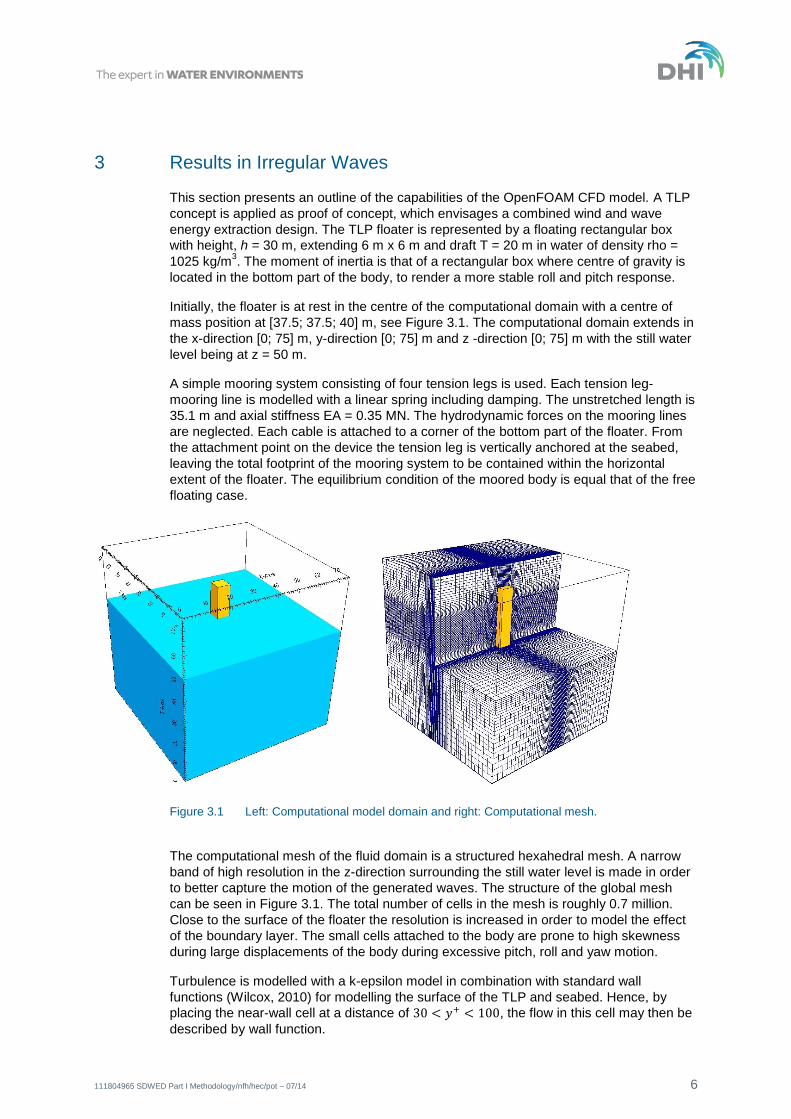
Initially, the floater is at rest in the centre of the computational domain with a centre of
mass position at [37.5; 37.5; 40] m, see Figure 3.1. The computational domain extends in
the x-direction [0; 75] m, y-direction [0; 75] m and z -direction [0; 75] m with the still water
level being at z = 50 m.
A simple mooring system consisting of four tension legs is used. Each tension leg-
mooring line is modelled with a linear spring including damping. The unstretched length is
35.1 m and axial stiffness EA = 0.35 MN. The hydrodynamic forces on the mooring lines
are neglected. Each cable is attached to a corner of the bottom part of the floater. From
the attachment point on the device the tension leg is vertically anchored at the seabed,
leaving the total footprint of the mooring system to be contained within the horizontal
extent of the floater. The equilibrium condition of the moored body is equal that of the free
floating case.
Figure 3.1 Left: Computational model domain and right: Computational mesh.
The computational mesh of the fluid domain is a structured hexahedral mesh. A narrow
band of high resolution in the z-direction surrounding the still water level is made in order
to better capture the motion of the generated waves. The structure of the global mesh
can be seen in Figure 3.1. The total number of cells in the mesh is roughly 0.7 million.
Close to the surface of the floater the resolution is increased in order to model the effect
of the boundary layer. The small cells attached to the body are prone to high skewness
during large displacements of the body during excessive pitch, roll and yaw motion.
Turbulence is modelled with a k-epsilon model in combination with standard wall
functions (Wilcox, 2010) for modelling the surface of the TLP and seabed. Hence, by
placing the near-wall cell at a distance of , the flow in this cell may then be
described by wall function.

111804965 SDWED Part I Methodology/nfh/hec/pot – 07/14 7
Active absorption is applied on all vertical boundaries of the computational domain, hence
removing the necessity of extending the domain in the wave direction (x-direction).
The wave conditions at the imagined site are represented by a JONSWAP spectrum
[DNV-RP-C205] with a peak enhancement parameter of 3.3, significant wave height m and peak wave period s. Only unidirectional waves were considered.
The spectrum is modelled by a series of sinusoidal wave components as outlined in
section 3.3.2 in DNV-RP-C205.
A minimum number of sinusoidal wave components needed to represent the theoretical
spectrum are computed, hence reducing the resolution. Due to the large computational
demand of the present complex model, the simulation time had to be limited to relatively
short time series. The time series were selected to 600 s (10 min). The time series were
chosen which best reproduced the wave spectra, and included one or more extreme
events within the 600 s. In other words, the wave spectra for the short time series do not
differ significantly from the corresponding spectra for full 3-hour time series. The spectra
applied in the CFD simulations are shown in Figure 3.2 together with the corresponding
time signal of the surface elevation. Figure 3.2 compares the CFD results of the free
wave fields to the analytically derived spectra based on linear theory. The input signals
and the simulated signals are in good agreement.
Figure 3.2 The JONSWAP wave spectra used as input to the CFD simulations; m,
s and gamma = 3.3. Right: Corresponding time signals of the surface
elevation.
Figure 3.3 shows a snapshot of the simulation in the crest of the wave at 37 s. The
distortion of the mesh due to motion of the TLP is evident.

111804965 SDWED Part I Methodology/nfh/hec/pot – 07/14 8
Figure 3.3 Snapshot of the solution state after 37 s. The iso-surface of the volume-fraction
variable in the VOF approach equal 0.5 is used to illustrate the free surface. The
surface is coloured such that maximum wave height is coloured white, minimum is
coloured blue. To the right is a close-up of the mesh surrounding the TLP.
Figure 3.4 depicts the motion response of the TLP. It can be observed that in case of the
current TLP configuration the floater is most sensitive to surge motion. As expected the
heave motion is of less dominant nature.
Figure 3.4 Displacement and angular motion of the floater moving in irregular waves.
Figure 3.5 illustrates the tension forces in the mooring lines at the attachment point.
Mooring line no. 1 no. and 2 are attached to the upstream corners of the floater and are
exposed to the largest forces as expected.

111804965 SDWED Part I Methodology/nfh/hec/pot – 07/14 9
Figure 3.5 The tension force magnitude at the attachment point to the floater in each of the four
mooring cables. To the left force components in mooring line no. 2.

111804965 SDWED Part I Methodology/nfh/hec/pot – 07/14 10
4 Developments and Methodology
A methodology for performing coupled analysis of floating WECs was presented. The
coupling of the free-surface Navier-Stokes solver and active wave boundary strategy has
been tested. The floater was subjected to a real sea state. Albeit no general conclusion
should be drawn from the present test case, it served to demonstrate that the 2-way
coupling approach between structure and water including the full non-linearity and
viscous effects can capture the complex interaction between the mooring system and the
floating structure. The results illustrated that the model is able to capture the transfer of
complicated wave impact forces qualitatively, due to non-linear wave interaction including
viscous effects, to the mooring system.
As described above the key OpenFOAM® components for advanced simulation of the 2-
way coupling between a floating structure and the surrounding sea are readily available.
Their specific application in this context is, however, only very scarcely validated. Building
up confidence in the code and possibly identify components that need to be improved is
the main objective of DHI’s activities under the SDWED under Work package 1.
Validations were performed including heave tests for simple structures as well as
convergence tests with respect to spatial mesh resolution and time step size. As part of
the validation the sensitivity of the solver to very large body displacements is an essential
investigation. For large body displacements and rotations the mesh quality degrades -
eventually to a level where the solver crashes. Gaining experience with the solver
robustness for large mesh deformations is an important part of mapping the application
envelope of the tool, including enhancing the model by including mesh with sliding mesh
motion on the top, bottom and side patches of the domain to allow for large surge
displacements with minimum mesh skewness. An extension of the mooring line
description library is invariable in order to include a detailed description of a mooring
system, which needless to say has a significant impact on the motion response of the
floating WEC.
For code validation against physical wave tank tests the extensively tested floating
breakwater by Ruol and Martinelli (2007) is applied together with our recently developed
wavemaker based on moving meshes. The wavemaker will be very useful as it can
accurately reproduce waves generated in the real physical test facilities. This test serves
to wash out the salient problems in the explicit pressure and body movement coupling,
which in some cases result in numerical instabilities due to a resulting artificial added
mass (Forster et al., 2007).
The main drawback of the CFD approach compared to codes such as WAMSIM is the
significantly increased computational times. Both within the SDWED project and other
research projects DHI is working continuously on optimizing the code performance.
Nevertheless in the years to come it is not realistic that CFD will replace potential codes.
Rather it will serve as an invaluable supplement extending the scope of numerical floater
design testing to more extreme sea states and viscously dominated situations. Its true
potential is to gradually replace expensive full and small-scale physical tests.
Finally, it should be mentioned that the OpenFOAM® surface capturing algorithm often
causes high artificial velocities parallel to the water surface in both the air and water
phase. Furthermore, the current VOF implementation requires a very regular mesh near
the free surface or it will become unstable. In a new research project DHI is investing
heavily in eliminating these problems by improving the VOF algorithm and its
implementation in OpenFOAM®. The improved stability and flexibility of the OpenFOAM®
free surface solver family derived from this project will feed directly into the SDWED
project.
111804965 SDWED Part I Methodology/nfh/hec/pot – 07/14 11
5 References
/1/ Berberovic E, Van Hinsberg NP, Jakirli´c S, Roisman IV, Tropea C. (2009) Drop
impact onto a liquid layer of finite thickness: dynamics of the cavity evolution.
Physical Review E Statistical, Nonlinear, and Soft Matter Physics 79(3):1–15.
Art.no: 036 306.
/2/ Christensen, E.D., Jensen, B., Mortensen, S., Hansen, H.F. and Kirkegaard, J.
(2008) Numerical Simulation of Ship Motion in Offshore and Harbour Areas, The
27th International Conference on Offshore Mechanics and Arctic Engineering
(OMAE 2008).
/3/ Deshpande, S.S., Anumolu , L. and Trujillo , M.F. (2012). Evaluating the
performance of the two-phase flow solver interFoam. Computational Science &
Discovery 5.
/4/ Dullweber A., Leimkuhler B., McLachlan R. (1997), Symplectic splitting methods for
rigid body molecular dynamics. J. Chem. Phys. 107 (15).
/5/ Environmental conditions and environmental loads, DNV-RP-C205.
Recommended Practice prepared by Det Norske Veritas, DNV, October 2010.
/6/ Förster C, Wall W. and Ramm E. (2007) Artificial added mass instabilities in
sequential staggered coupling of nonlinear structures and incompressible viscous
flows. Comput Methods Appl Mech Eng 196(7):1278–93.
/7/ Higuera, P., Lara, J.L. and Losada, I.J. (2013). Realistic wave generation and
active wave absorption for Navier–Stokes models. Application to OpenFOAM.
Coastal Engineering.
/8/ Hirt C.W, Nichols B.D. (1981) Volume of fluid (VOF) method for the dynamics of
free boundaries. Journal of Computational Physics 39(1):201–225.
/9/ Jacobsen, N.G., Fuhrman, D.R., Fredsøe, J. (2012), A wave generation toolbox for
the open-source CFD library: OpenFoam®. Int. J. Numer. Meth. Fluids 70(9):
1073–1088.
/10/ Jasak, H. (1996): Error Analysis and Estimation for the Finite Volume Method with
Applications to Fluid Flows PhD thesis submitted to the Department of Mechanical
Engineering, Imperial College of Science, Technology and Medicine, June 1996.
/11/ Jasak, H. (2009) Dynamic Mesh Handling in OpenFOAM, 48th AIAA Aerospace
Sciences Meeting, Orlando, Florida.
/12/ Jasak, H. and Tukovic, Z. (2010) Dynamic mesh handling in OpenFOAM applied to
fluid-structure interaction simulations V European Conference on Computational
Fluid Dynamics, ECCOMAS CFD, Lisbon, 14-17 June.
/13/ Rusche, H. (2002) Computational fluid dynamics of dispersed two-phase flows at
high phase fractions. PHD Thesis, Imperial College of Science, Technology and
Medicine, UK.
/14/ Ruol P. and Martinelli L. (2007) Wave flume investigation on different mooring
systems for floating breakwaters. In: Proc. coastal structure'07.

111804965 SDWED Part I Methodology/nfh/hec/pot – 07/14 12
/15/ Weller HG, Tabor G, Jasak H and Fureby C (1998): A tensorial approach to
computational continuum mechanics using object oriented techniques, Comput.
Phys. 12, 620.
/16/ Weller, H.G. (2002) Derivation, modelling and solution of the conditionally
averaged two-phase flow equations Technical Report TR/HGW/02, Nabla Ltd.
/17/ Wilcox, DC (2010). “Turbulence Modeling for CFD”. Third Edition, DCW
Industries, Inc., La Canada, CA.