structural evolution and formation mechanisms of tic/ti nanocomposites prepared by high-energy...
TRANSCRIPT

Structural evolution and formation mechanisms of TiC/Ti nanocomposites prepared by high-
energy mechanical alloying
This article has been downloaded from IOPscience. Please scroll down to see the full text article.
2010 J. Phys. D: Appl. Phys. 43 135402
(http://iopscience.iop.org/0022-3727/43/13/135402)
Download details:
IP Address: 128.103.149.52
The article was downloaded on 01/05/2013 at 14:43
Please note that terms and conditions apply.
View the table of contents for this issue, or go to the journal homepage for more
Home Search Collections Journals About Contact us My IOPscience

IOP PUBLISHING JOURNAL OF PHYSICS D: APPLIED PHYSICS
J. Phys. D: Appl. Phys. 43 (2010) 135402 (11pp) doi:10.1088/0022-3727/43/13/135402
Structural evolution and formationmechanisms of TiC/Ti nanocompositesprepared by high-energy mechanicalalloyingDongdong Gu1,2, Wilhelm Meiners1, Yves-christian Hagedorn1,Konrad Wissenbach1 and Reinhart Poprawe1
1 Fraunhofer Institute for Laser Technology ILT/Chair for Laser Technology LLT, RWTH Aachen,Steinbachstraße 15, D-52074 Aachen, Germany2 College of Materials Science and Technology, Nanjing University of Aeronautics and Astronautics,29 Yudao Street, 210016 Nanjing, People’s Republic of China
E-mail: [email protected] and [email protected]
Received 18 November 2009, in final form 1 February 2010Published 18 March 2010Online at stacks.iop.org/JPhysD/43/135402
AbstractIn this work, high-energy ball milling of a micrometre-scaled Ti and TiC powder mixture wasperformed to prepare TiC/Ti nanocomposites. The constituent phases and microstructuralcharacteristics of the milled powders were studied by an x-ray diffractometer, a scanningelectron microscope, an energy dispersive x-ray spectroscope and a transmission electronmicroscope. Formation mechanisms and theoretical basis of the microstructural developmentwere elucidated. It showed that on increasing the applied milling time, the structures of the Ticonstituent experienced a successive change from hcp (5 h) to fcc (10 h) and finally to anamorphous state (�15 h). The hydrostatic stresses caused by the excess free volume at grainboundaries were calculated to be 3.96 and 5.59 GPa for the Ti constituent in 5 and 10 h milledpowders, which was responsible for the hcp to fcc polymorphic change. The amorphization ofTi constituent was due to the large defect concentration induced by severe plastic deformationduring milling. The milled powder particles underwent two stages of significant refinement at10 and 20 h during milling. For a higher milling time above 25 h, powder characteristics andchemical compositions became stable. The competitive action and the final equilibriumbetween the mechanisms of fracturing and cold welding accounted for the microstructuralevolution. The ball milled products were typically nanocomposite powders featured by ananocrystalline/amorphous Ti matrix reinforced with uniformly dispersed TiC nanoparticles.The finest crystalline sizes of the Ti and TiC constituents were 17.2 nm (after 10 h milling) and13.5 nm (after 20 h milling), respectively.
(Some figures in this article are in colour only in the electronic version)
1. Introduction
In recent years, the continuing need for lightweight andhigh performance materials to satisfy the demands fromthe aerospace and automotive industries has provided thenecessary impetus for the development of many innovative
combinations of materials. Abundant research efforts havebeen focused on the design and synthesis of high performancemetal matrix composites (MMCs), which are regarded asattractive alternatives to the traditional and newer generationof unreinforced metallic alloys [1–3]. A large majority ofthese MMCs are metal matrices reinforced with ceramic
0022-3727/10/135402+11$30.00 1 © 2010 IOP Publishing Ltd Printed in the UK & the USA

J. Phys. D: Appl. Phys. 43 (2010) 135402 D Gu et al
phases, which are typically in the discontinuous form ofparticulates dispersed in matrices. Amongst MMCs for hightemperature applications (e.g. functional aircraft and aerospacecomponents), ceramics reinforced Ti matrix compositescombine the high strength and stiffness of reinforcements withthe toughness and damage tolerance of Ti matrix, offeringattractive high temperature properties such as enhancedelevated temperature strength, good creep performance,fatigue resistance and wear resistance [4]. Particularly, theTiC ceramic, due to its stable, unreactive nature with theTi constituent, is regarded as one of the most favourablereinforcements for Ti-based MMCs.
It is known that the particulate size of the reinforcementhas a strong influence on the strength, ductility and failuremode of MMCs [5]. Large ceramic particulates tend to crackduring mechanical loading, resulting in premature failure andlow ductility of composites. Therefore, decreasing the ceramicparticulate size can lead to a substantial improvement in themechanical performance of MMCs. The use of nanoparticlesto reinforce metallic materials has inspired considerableresearch interest in recent years because of the potentialdevelopment of novel composites with unique properties[6, 7]. Such materials are termed nanocomposites. Toobtain desirable properties of nanocomposites, the reinforcingnanoparticles are required to be dispersed uniformly withinthe metal matrix. However, a homogeneous dispersion ofnanometre-scaled particles within the matrix cannot be easilyachieved, since nanoparticles generally possess an extremelylarge specific surface area and the attendant enhanced kineticsof aggregation.
In this respect, high-energy mechanical alloying (MA)is a well-developed process for dispersing nanocrystallinereinforcing particulates more uniformly in a metal matrix[8–15]. An ultrafine nanocrystalline nature coupled with ahomogeneous distribution of the reinforcing particulates isexpected to improve the obtainable mechanical properties ofnanocomposites prepared by the MA route [16]. MA, as a non-equilibrium, low temperature and solid-state powder treatmentprocess, involves repeated cold welding, fracturing and re-welding of powder particles in a high-energy ball mill [17–21].The advantage of using MA for the synthesis of nanocompositematerials lies in its ability to produce large quantities ofmaterial in the solid state using simple equipment and atroom temperature. Nevertheless, MA is a complex processand accordingly involves a large degree of uncertainty inobtaining the desired phases and microstructures. Significantexperimental studies are still required to study how thephases, microstructures and compositions of MA processednanocomposite powders evolve during high-energy ballmilling. Theoretical understanding of formation mechanismsbehind the microstructural development of the milled powdersis also regarded necessary.
In this work, nanocrystalline TiC particulate reinforcedTi-based nanocomposite powders were synthesized by MAof a mixture consisting of micrometre-sized Ti and TiCcomponents. The phase, microstructure and compositiontransformations of the milled nanocomposite powders werecharacterized and reasonable mechanisms for the structuralformation during the MA process were elucidated.
2. Experimental
2.1. Materials
The starting powder components include 99.9% purity Tipowder having a polygonal structure and a mean particle sizeof 45 µm (supplier: Beijing Mountain Technical DevelopmentCenter for Non-Ferrous Metals, PR China) and 99.8% purityTiC powder with an irregular shape and an average particlesize of 1.5 µm (supplier: Zhuzhou Cemented Carbides GroupCo., Ltd, PR China). Powder mixtures containing 15 g TiC and35 g Ti were weighed and mixed. The weight ratio of TiC andTi was 30 : 70 and the equivalent volume ratio was 28.2 : 71.8.
2.2. Processing
Ball milling was performed in a high-energy Pulverisette6 planetary mono-mill (supplier: Fritsch GmbH, Germany).A hardened chromium steel grinding bowl was used, whoseuseful capacity was 125 ml. Stainless steel grinding balls (ten∅20 balls + thirty-five ∅10 balls + thirty-five ∅6 balls, a totalweight of 500 g) and 50 g powder mixture to be ground werecharged into the grinding bowl with a ball-to-powder weightratio of 10 : 1. MA treatment was under the protection of argonatmosphere to avoid oxidation of the powders. Six differentmilling times, 5, 10, 15, 20, 25 and 30 h, were set periodically,while the rotation speed of the main disc was fixed at 250 rpm.In order to avoid excessive temperature rise within the grindingbowl, 20 min ball milling duration was followed by an intervalof 10 min.
2.3. Characterization
The particle sizes of the milled powders were evaluated usinga Mastersizer 2000 laser particle size analyzer (supplier:Malvern Instruments Ltd, UK). The phases of the milledpowders were identified by a Bruker D8 Advance x-raydiffractometer (XRD) with Cu Kα radiation (λ = 0.154 18 nm)at 40 kV and 40 mA using a continuous scan mode. A quickscan of 4◦ min−1 was primarily performed over a wide rangeof 2θ of 25◦–110◦. A slower scan rate of 1◦ min−1 wasfurther used over the 2θ range 32◦–46◦ to give a more accuratedetermination of diffraction peaks. The sizes of the crystalliteswere determined based on XRD peak broadening using theScherrer formula:
D = 0.9λ
β cos θ, (1)
where β is the full width at half maximum of the XRD peak,θ the diffraction angle, λ the wave length of x-ray and D theaverage grain size. The microstructural features of the powderswere characterized using a FEI Quanta 200 scanning electronmicroscope (SEM) at an accelerating voltage of 20 kV. AnEDAX Genesis energy dispersive x-ray spectroscope (EDX)was used to determine the chemical compositions, using asuper-ultra thin window (SUTW) sapphire detector. Thenanostructures obtained in as-milled powders (e.g. grain sizeand crystal structure) were studied using a JEOL JEM-2100transmission electron microscope (TEM).
2
J. Phys. D: Appl. Phys. 43 (2010) 135402 D Gu et al
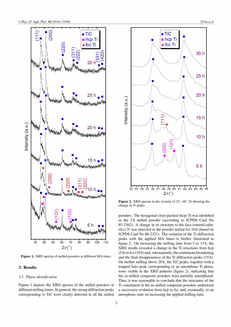
Figure 1. XRD spectra of milled powders at different MA times.
3. Results
3.1. Phase identification
Figure 1 depicts the XRD spectra of the milled powders atdifferent milling times. In general, the strong diffraction peakscorresponding to TiC were clearly detected in all the milled
Figure 2. XRD spectra in the vicinity of 32◦–46◦ 2θ showing thechange in Ti peaks.
powders. The hexagonal-close-packed (hcp) Ti was identifiedin the 5 h milled powder (according to JCPDS Card No65-3362). A change in its structure to the face-centred-cubic(fcc) Ti was detected in the powder milled for 10 h (based onJCPDS Card No 88-2321). The variation of the Ti diffractionpeaks with the applied MA times is further illustrated infigure 2. On increasing the milling time from 5 to 15 h, theXRD results revealed a change in the Ti structures from hcp(5 h) to fcc (10 h) and, subsequently, the continuous broadeningand the final disappearance of the Ti diffraction peaks (15 h).On further milling above 20 h, the TiC peaks, together with atrapped halo peak corresponding to an amorphous Ti phase,were visible in the XRD patterns (figure 2), indicating thatthe as-milled composite powders were partially amorphized.Thus, it was reasonable to conclude that the structures of theTi constituent in the as-milled composite powders underwenta successive evolution from hcp to fcc and, eventually, to anamorphous state on increasing the applied milling time.
3

J. Phys. D: Appl. Phys. 43 (2010) 135402 D Gu et al
Figure 3. Estimated crystallite sizes of TiC and Ti phases at variousMA times.
The average crystalline sizes of the TiC and the Ti phasesat different milling times were calculated based on XRD peakbroadening using equation (1), as revealed in figure 3. Onprolonging the milling time from 5 to 20 h, the TiC crystallinesize decreased gradually from 22.8 to 13.5 nm. A furtherincrease in the milling time above 25 h, however, resulted in asignificant growth of TiC grains to 29.0 nm, which remainedsteady at 29.8 nm as the milling time reached 30 h. The meancrystalline size of the Ti constituent in the milled crystalline-state powder decreased from 25.4 to 17.2 nm as the millingtime extended from 5 to 10 h.
3.2. Microstructures and compositions
The microstructural development of the milled powders withthe applied MA times is shown in figure 4. Figure 5depicts the particle sizes of the corresponding powders.The high-magnification characteristics of the milled powderparticles are provided in figure 6. It revealed that themicrostructural features of the milled powders (e.g. particleshape, surface structure, particle size and its distribution,and powder dispersion state) were significantly influencedby the applied MA time. After 5 h of milling, the startingirregularly shaped powder particles underwent a preliminaryfracture (figure 4(a)), with the mean particle size decreasedto 31.3 µm (figure 5). The distribution of particle sizes inthis case, however, showed a certain degree of non-uniformity(figure 4(a)). On increasing the milling time to 10 h, themilled powder was fractured intensively to form fine particles(figure 4(b)), resulting in a sharp decrease in the averageparticle size to 6.2 µm (figure 5). The surface of particles wassmooth and compact (figure 6(a)). Interestingly, on millingup to 15 h, significantly coarsened powder particles having apoly-angular structure (figure 4(c)) and a large average sizeof 69.7 µm (figure 5) were formed. High-magnification SEMmicrograph revealed that the particle surface was considerablyrough and loose and consisted of a large number of ultrafineparticulates (figure 6(b)). The large-sized particles fractured
again when the MA time prolonged to 20 h, exhibiting arefined, homogeneous microstructure (figure 4(d)). The meanparticle size decreased markedly to 18.9 µm (figure 5) and theparticle surface was smoothed (figure 6(c)). At an even highermilling time of 25 h, the powder particles were coarsenedagain (figure 4(e)), thereby increasing the average particlesize to 46.3 µm (figure 5). At this instance, the particlesurface again became rough and heterogeneous (figure 6(d)).A further increase in the applied milling time to 30 h did notcause a substantial change in particle morphology, although theparticle size distribution became a bit broader (figure 4(f ))and the average particle size increased slightly to 48.5 µm(figure 5). From the review of figures 4–6, it was revealedthat the powder particles underwent two stages of significantrefinement during the ball milling process (10 and 20 h) and,subsequently, the particle structure gradually entered a stablestate as the milling time extended above 25 h.
In order to further determine the chemical compositionsof the milled powders, EDX characterization at selected areason particle surfaces, as indicated by squares in figure 6,was performed, with the results listed in figure 7. It wasobserved that the C elemental concentration on the particlesurface decreased significantly from 11.34 wt% (figure 7(a))to 7.96 wt% (figure 7(b)) when the milled powder changedits shape from a refined one (10 h milling, figure 6(a)) to aconsiderably coarsened one (15 h milling, figure 6(b)). In thissituation, it was reasonable to conclude that with the action ofcontinuous powder–ball collisions and inter-particle collisions,more TiC particulates penetrated from the surface deep intothe interior matrix of the Ti particles. On further millingup to 20 h, the weight fraction of the C element measuredon the surface of the re-fractured fine particles (figure 6(c))again showed an increase to 10.97 wt% (figure 7(c)). Underthis condition, fresh surfaces were continuously created dueto the fracture of the TiC/Ti nanocomposite powder particles,thereby exposing more TiC particulates on the newly formedsurfaces. As the applied milling time prolonged to 25 h,the detected C elemental content, 11.01 wt%, showed noapparent change (figure 7(d)). In this case, a steady state ofpowder characteristics (including chemical compositions) wasobtained within the as-milled powder.
TEM microstructural characterization was performed tostudy the milled powders in terms of nanostructure andamorphization. Figure 8 shows a bright-field micrographalong with the corresponding selected area diffraction pattern(SADP) of the 10 h milled powder. As revealed in figure 8(b),the rings in the SADP allowed us to identify the Ti and TiCphases. The rings indicated a considerably small size ofcrystallites of both phases, confirming the nanocrystallinityof the as-milled powder. In particular, the identified rings ofTi constituent, Ti (2 0 0) and Ti (2 2 2), exactly corresponded tothe fcc Ti (figure 8(b)), which further confirmed the presenceof fcc Ti matrix after 10 h milling (figure 1). The bright-field image showed that the particle of the milled productconsisted of a large number of ultrafine crystallites of TiCand Ti with sizes less than 25 nm (figure 8(a)). Thus, theaverage crystalline sizes of the TiC and Ti phases determinedby the XRD method (figure 3) were consistent with the TEM
4

J. Phys. D: Appl. Phys. 43 (2010) 135402 D Gu et al
Figure 4. SEM images showing characteristic microstructures of milled powders at various MA times: (a) 5 h; (b) 10 h; (c) 15 h; (d) 20 h;(e) 25 h; (f ) 30 h.
results. Furthermore, it was observed that the nanometre-sizedTiC particulates were dispersed uniformly throughout the Timatrix (figure 8(a)). Combined with the XRD and TEM results(figures 1, 2 and 8), it was reasonable to conclude that the 10 hmilled product was a typical nanocomposite powder featuredby a nanocrystalline fcc-structured Ti matrix reinforced withthe TiC nanoparticles.
The bright-field image and the corresponding SADPof the composite powder after 20 h milling are providedin figures 9(a) and (b), respectively. A high-resolutiontransmission electron microscopy (HRTEM) image of a
selected edge region is shown in figure 9(c). All the continuousspotty rings in the SADP corresponded to TiC, indicating thenanocrystallinity of the TiC constituent in the milled powder(figure 9(b)). A homogeneous dispersion of nanocrystallineTiC particulates having a mean crystalline size of ∼10 nmwas obtainable within the matrix (figure 9(a)). The HRTEMimage in figure 9(c) revealed that the crystalline phase,with an interplanar spacing d = 0.321 nm, coexisted withthe amorphous phase. The regions of structural disorder(shown by arrows in figure 9(c)) possibly had an amorphousstructure. Crystalline regions having clear atomic planes were
5

J. Phys. D: Appl. Phys. 43 (2010) 135402 D Gu et al
Figure 5. Change in average particle sizes of milled powders withMA times.
interspersed in the amorphous regions. Combined with theXRD results, this suggested the presence of a nanocompositestructure consisting of the amorphous Ti matrix and thenanocrystalline TiC phase in the 20 h milled powder.
4. Discussion
4.1. Mechanisms of phase transformation
A reasonable explanation for the phase transformation of Ticonstituent during ball milling (hcp → fcc → amorphous,figures 1, 2 and 9) can be proposed by considering thenegative hydrostatic pressure (P(V )) developed at the grainboundaries of the nanocrystalline materials as a function ofthe excess free volume (�VF). According to Phillpot et al’swork [22], the atoms at the boundaries of nanometre-scaledgrains may be randomly displaced from their regular atomicsites to the maximum extent of half of the distance to thenearest neighbours. Furthermore, the atomic structure of grainboundaries basically lacks long-range periodicity parallel tothe interface. The atoms at grain boundaries, therefore, willhave one additional degree of freedom of migration along theboundary plane than those in the inside bulk crystals [23]. Inthis situation, the excess free volume �VF associated withthe atoms at grain boundaries tends to be generated. Thedimensionless value of �VF can be defined as [23]
�VF = (dc + δ/2)2 − d2c
d2c
, (2)
where dc is the grain size of the given nanocrystals andδ (normally 1 nm) is the thickness of the grain boundaryplane assumed to be independent of dc. As revealed infigure 3, on increasing the milling time from 5 to 10 h, theaverage grain size of the milled Ti constituent decreases from25.4 to 17.2 nm, leading to a large (48.2%) increase in �VF
from 0.0398 to 0.0590. On the other hand, the volumeexpansion (lattice expansion) tends to simultaneously generatethe residual compressive stress on grain boundaries. Based on
Fecht’s results [24], an increase in �VF induced by a decease inthe grain size will develop a negative (from core to periphery)hydrostatic pressure (P(V )) at the grain boundaries, which isexpressed as
P(V ) = −3B0[(V/V0)1/3 − 1]
(V/V0)2/3
× exp(−a∗)(1 − 0.15a∗ + 0.05a∗2), (3)
where B0 is the equilibrium bulk modulus, V0 is the equilibriumspecific volume per atom and a∗ is a scaling parameterdefined as
a∗ = (rws − rwse)/ l. (4)
Here, rwse is the equilibrium radius of the Wigner–Seitz cell(Ti rwse = 0.162 nm [25]), rws is the real Weigner–Seitzcell radius of the atom with a volume V and l is the lengthscale characteristic for the material (Ti l = 0.034 nm [25]).The atomic volumes V and V0 are thus approximated by aspherical model as 4πr3
ws/3 and 4πr3wse/3, respectively. It is
noted that in continuum mechanics, the hydrostatic stress isan isotropic stress that is given by the weight of the materialabove a certain point and, thus, it is used interchangeablywith the hydrostatic pressure. In this situation, −P(V ) isthe magnitude of the hydrostatic stress corresponding to thenegative pressure originated due to the excess free volumeat grain boundaries [23]. Adopting the above equations,the corresponding −P(V ) values of Ti constituent in the5 h and 10 h milled powders are calculated to be 3.96 GPaand 5.59 GPa, respectively. It is believed that a substantialincrease in −P(V ) at grain boundaries of nanocrystallineTi constituent induces a significant structural instability andeventually causes a hcp to fcc polymorphic change (figures 1and 2). In order to further prove the occurrence of hcp → fcctransformation during 5–10 h milling, an increment in theelastic strain energy (�U) of Ti constituent is calculated:
�U = [(−P(V ))10 h − (−P(V ))5 h] × (Va, fcc − Va, hcp).
(5)
It is known that the atomic radius r and the volume per atom(Va) in the fcc unit cell of Ti are 0.1540 nm and 0.0207 nm3,respectively. In comparison, r and Va for hcp Ti are 0.1448 nmand 0.0177 nm3, respectively [26]. The elastic strain energyincrement �U is thus calculated as 4.9 × 10⁻²¹ J/atom, whichis very close to the magnitude for the theoretically predictedchange of hcp Ti to fcc Ti (5.5 × 10⁻²¹ J/atom [27]).
The experimental results also reveal that for a millingtime beyond 15 h, amorphization of the Ti constituent occursin the milled powder (figures 1, 2 and 9). A basic premisefor amorphous phase formation is that a critical defectconcentration introduced by severe plastic deformation willpromote spontaneous transformation to the amorphous state.At this defect concentration, it requires that [28]
Gc + �Gd > Ga, (6)
where Gc is the free energy of the crystalline phase, �Gd
is the increase in free energy due to the defects producedby ball milling and Ga is the free energy of the amorphous
6

J. Phys. D: Appl. Phys. 43 (2010) 135402 D Gu et al
Figure 6. SEM images showing high-magnification particle morphologies of milled powders after (a) 10 h; (b) 15 h; (c) 20 h; (d) 25 hmilling. Due to a significant difference in particle sizes, different magnifications were used in SEM characterization to obtain suitableimages. To make particle sizes comparable, scale bars having the same bar length and various actual sizes are provided in the bottom-rightcorner of each micrograph.
phase. Gc can be further expressed by the Gibbs–Thompsonequation [29]:
Gc = 4γVm/dc, (7)
where γ is the interfacial energy and Vm is the molar volume.On the one hand, during the foregoing 10 h milling duration,a significant reduction in dc and an increase in Vm may resultin a significant increase in Gc. On the other hand, with theapplied milling time prolonged (�15 h), the continuous severeplastic deformation of the milled powder will generate a largenumber of point and lattice defects (e.g. vacancies, interstitialsand dislocations), which further increases�Gd. The combinedeffect of these two aspects, consequently, raises the free energyof the Ti constituent above that of the amorphous phase(Ga), resulting in the amorphization of Ti by means of along-time MA.
4.2. Mechanisms of structural evolution
During high-energy ball milling, the powder particles arerepeatedly flattened, cold-welded, fractured and re-welded.Typically, whenever two grinding balls collide, around 1000particles with an aggregate weight of ∼0.2 mg are trapped inbetween them during each collision [17]. The force of theimpact plastically deforms the powder particles, resulting inwork hardening and fracture. On the other hand, the newsurfaces created enable the particles to weld together, therebyincreasing the obtainable particle size. The TiC–Ti composite
system as investigated falls in the brittle–ductile componentscombination and the microstructure of the final product isfeatured by the relatively brittle TiC ceramic particulatesdispersed within the ductile Ti matrix. The microstructuraldevelopment of the TiC/Ti nanocomposite powder during ballmilling depends on the competitive action/response betweenthe fracturing and cold welding. Figure 10 depicts a reasonablemechanism for the formation of TiC nanoparticle reinforcedTi matrix nanocomposite powder by high-energy ball milling.
(i) Fracturing stage (0–10 h). At the initial stage of milling,powder particles get trapped between the grinding ballsand undergo severe plastic deformation repeatedly dueto the impact forces imposed on them by the grindingmedium. The fracturing mechanism thus predominatesat this stage. The ductile Ti powder particles getdeformed, flattened and fractured by the ball–powder–ball collisions (figures 4(b) and 6(a)). Due to the highdeformation rate experienced by the ductile Ti constituent,shear bands, which contain a high dislocation density,tend to develop inside. Within these heavily strainedregions, the Ti crystal disintegrates into subgrains that areseparated by low-angle grain boundaries. With continuedmilling, deformation occurs in shear bands, making theshear bands coalesce. The small angle boundaries are,accordingly, replaced by higher angle grain boundaries,leading to the grain rotation and the attendant formation ofnanocrystalline Ti grains [17], as reflected by the random
7

J. Phys. D: Appl. Phys. 43 (2010) 135402 D Gu et al
Figure 7. (a)–(d) EDX analyses showing elemental compositions measured on particle surfaces in figures 6(a)–(d).
orientation of the nanocrystalline grains observed from theTEM micrograph (figure 8(a)). On the other hand, TiCparticles, due to their brittle nature, become fragmentedand comminuted during milling and their particle sizegets reduced continuously to a nanometre scale. Thesefragmented TiC nanoparticles tend to get occluded by theductile Ti constituent and trapped in the Ti particles, henceyielding the TiC/Ti nanocomposite powder.
(ii) Cold-welding stage (10–15 h). With ball millingcontinued, the nanocomposite powder experiencesa heavy plastic deformation, thereby significantlyincreasing the affinity activity of the newly createdparticle surfaces. As the cold-welding mechanismprevails, these fine particles get cold-welded together andform significantly coarsened TiC/Ti composite powder(figures 4(c) and 6(b)). The brittle TiC nanoparticlesinside the composite powder, nevertheless, undergo afurther refinement and get uniformly dispersed within thematrix, due to the continuous impact of grinding balls(figure 3).
(iii) Re-fracturing stage (15–25 h). On increasing themilling time, the nanocomposite powder particles getwork-hardened and have limited ability to accept a
further plastic deformation, resulting in the absence ofagglomerating forces. Consequently, the tendency tofracture, once more, starts to predominate over the coldwelding. The powder particles thus get fractured again(figures 4(d), 6(c) and 7(c)). On the other hand, thediffusion distance between TiC nanoparticles reducesdue to the effects of severe plastic deformation and theenhanced defect density and a local temperature rise[30]. In this situation, a slight coarsening of the TiCnanoparticles occurs due to the elevated diffusion in theinterfacial regions of the nanocrystalline grains (figure 3).
(iv) Equilibrium stage (>25 h). Further milling above 25 hproduces a steady state equilibrium in the milling systemas a balance is gradually reached between the rate offracturing, which tends to decrease the mean compositeparticle size, and the rate of cold welding, which tendsto increase the average particle size. In other words,the particles larger than average are reduced in size atthe same rate as the fragments smaller than averagegrow via agglomeration of smaller particles. Under thiscondition, stable powder characteristics and chemicalhomogeneity are achievable in the milled nanocompositepowder (figures 4(e) and (f ), figures 7(c) and (d)).
8

J. Phys. D: Appl. Phys. 43 (2010) 135402 D Gu et al
Figure 8. TEM micrograph (a) and the corresponding SADP (b) ofTiC/Ti nanocomposite powder milled for 10 h.
In this study, the TiC reinforcing phase is exteriorly addedand the ball milled TiC/Ti nanocomposite powder experiencesthe above-mentioned structural evolution (figures 4 and 10) dueto the competitive predominance between the cold-weldingand fracturing mechanisms. On the other hand, our previouswork on high-energy MA of a Ti–Al–graphite elementalpowder mixture reveals that the in situ formed TiC particulatereinforced Ti(Al) solid solution matrix nanocomposite powdercan be produced [16]. In this instance, the competitionbetween cold welding and fracturing of particles is also foundto account for the microstructural alteration of the milledpowders. Nevertheless, the two material systems demonstratedistinctly different physical and chemical mechanisms forthe phase developments during MA. For the TiC–Ti systemas investigated, a successive hcp → fcc → amorphousphase transformation of the Ti constituent is detected duringmilling and the dominant physical mechanisms of such atransformation have been explained in detail in section 4.1.Differently, for the Ti–Al–graphite in situ synthesis system,the TiC phase is produced through an abrupt, exothermicand self-sustaining reaction between Ti and C elements and,meanwhile, the Ti(Al) solid solution is formed by the gradualand progressive solution of Al into Ti lattice [16]. Thus,for different powder systems (even if consisting of somesimilar constituents), the dominant physical and chemicalmechanisms behind the microstructural developments of themilled powders may vary significantly and, thus, should becarefully determined.
Figure 9. TEM micrograph (a) and the corresponding SADP (b) ofTiC/Ti nanocomposite powder milled for 20 h. HRTEM image ofthe selected boundary region of the powder showing the coexistenceof nanocrystallites and the amorphous phase (c).
5. Conclusions
High-energy ball milling of a micrometre-scaled Ti andTiC powder mixture was performed to prepare TiC/Tinanocomposite powders. The main conclusions were drawnas follows:
(1) The structures of the Ti constituent in the milledpowders underwent a successive evolution as the millingtime extended: hcp (5 h)–fcc (10 h)–an amorphous state(�15 h). The hydrostatic stresses originated due to theexcess free volume at grain boundaries were calculated tobe 3.96 and 5.59 GPa for the Ti constituent in the 5 and 10 hmilled powders, which was responsible for the hcp to fccpolymorphic change. The formation of the Ti amorphous
9

J. Phys. D: Appl. Phys. 43 (2010) 135402 D Gu et al
Figure 10. Schematic of structural development during MA of TiC/Ti nanocomposite powder.
phase was due to the large defect concentration caused bysevere plastic deformation during milling.
(2) The milled powder particles experienced two stages ofsignificant refinement at 10 and 20 h during milling.The microstructural development was ascribed to thecompetitive action/response between the mechanismsof fracturing and cold welding. The powder featuresand chemical compositions became stable in the millednanocomposite powder for a longer milling time above25 h due to a balance between the rate of fracturing andcold welding.
(3) The ball milled products were generally nanocompositepowders featured by the nanocrystalline/amorphousTi matrix reinforced with the well-dispersed TiCnanoparticles. The crystalline size of the Ti constituentwas 17.2 nm in the 10 h milled crystalline-state powder.The finest TiC crystalline size, 13.5 nm, was obtainableafter 20 h milling.
Acknowledgments
One of the authors (Dongdong Gu) gratefully appreciatesthe financial support from the Alexander von HumboldtFoundation and the Jiangsu Provincial Natural ScienceFoundation (Grant No BK2009374).
References
[1] Moya J S, Lopez-Esteban S and Pecharroman C 2007 Prog.Mater. Sci. 52 1017–90
[2] Tjong S C and Ma Z Y 2000 Mater. Sci. Eng. R 29 49–113[3] Viswanathan V, Laha T, Balani K, Agarwal A and Seal S 2006
Mater. Sci. Eng. R 54 121–285[4] Xiao L, Lu W J, Yang Z F, Qin J N, Zhang D, Wang M M,
Zhu F and Ji B 2008 Mater. Sci. Eng. A 491 192–8[5] Tjong S C 2007 Adv. Eng. Mater. 9 639–52[6] Zerkout S, Achour S and Tabet N 2007 J. Phys. D: Appl. Phys.
40 7508–14[7] Zhong X L and Gupta M 2008 J. Phys. D: Appl. Phys.
41 095403[8] Crespo P, Neu V and Schultz L 1997 J. Phys. D: Appl. Phys.
30 2298–303[9] Geng D Y, Zhang Z D, Liu W, Zhao X G, Yu M H, Ren W J,
Xiao Q F, Grossinger R and Hauser R 2003 J. Phys. D:Appl. Phys. 36 375–9
[10] Menendez E, Sort J, Concustell A, Surinach S, Nogues J andBaro M D 2007 Nanotechnology 18 185609
[11] Krasnowski M and Kulik T 2007 Intermetallics 15 1377–83[12] Karimzadeh F, Enayati M H and Tavoosi M 2008 Mater. Sci.
Eng. A 486 45–8[13] Forouzanmehr N, Karimzadeh F and Enayati M H 2009
J. Alloys Compounds 478 257–9[14] Parvin N, Assadifard R, Safarzadeh P, Sheibani S and
Marashi P 2008 Mater. Sci. Eng. A 492 134–40[15] Arami H, Simchi A and Seyed Reihani S M 2008 J. Alloys
Compounds 465 151–6[16] Gu D D and Shen Y F 2009 Adv. Eng. Mater. 11 573–8[17] Suryanarayana C 2001 Prog. Mater. Sci. 46 1–184[18] Hesabi Z R, Kamrani S, Simchi A and Reihani S M S 2009
Powder Metall. 52 151–7[19] Al-Aqeeli N, Mendoza-Suarez G, Suryanarayana C and
Drew R A L 2008 Mater. Sci. Eng. A 480 392–6[20] Sadeghian Z, Enayati M H and Beiss P 2009 J. Mater. Sci.
44 2566–72[21] Zakeri M, Rahimipour M R and Khanmohammadian A 2008
J. Mater. Sci. 43 6912–9
10

J. Phys. D: Appl. Phys. 43 (2010) 135402 D Gu et al
[22] Phillpot S R, Wolf D and Gleiter H 1995 J. Appl. Phys.78 847–61
[23] Chattopadhyay P P, Nambissan P M G, Pabi S K and Manna I2001 Phys. Rev. B 63 054107
[24] Fecht H J 1990 Acta Metall. Mater. 38 1927–32[25] Rose J H, Smith J R, Guinea F and Ferrante J 1984
Phys. Rev. B 29 2963–9[26] Cullity B D 1978 Elements of X-Ray Diffraction
(Reading, MA: Addison-Wesley)
[27] Kaufman L 1966 Phase Stability in Metals and Alloysed P S Rudman et al (London: McGraw-Hill)pp 125
[28] Schwarz R B and Koch C C 1986 Appl. Phys. Lett.49 146–8
[29] Manna I, Chattopadhyay P P, Nandi P, Banhart F and Fecht H J2003 J. Appl. Phys. 93 1520–4
[30] Davis R M, McDermott B and Koch C C 1988Metall. Trans. A 19 2867–74
11