structural performance of a steep slope landfill … university institutional repository structural...
TRANSCRIPT
Loughborough UniversityInstitutional Repository
Structural performance of asteep slope landfill lining
system
This item was submitted to Loughborough University's Institutional Repositoryby the/an author.
Citation: DIXON, N., NG'AMBI, S. and JONES, D.R.V., 2004. Structuralperformance of a steep slope landfill lining system. Proceedings of ICE, Geotech-nical Engineering, 157(GE3), pp. 115�125.
Additional Information:
• This article was published in the journal, Proceedings of ICE,Geotechnical Engineering [ c© Institution of Civil Engineers /Thomas Telford] and the definitive version is available at:http://www.thomastelford.com/journals/
Metadata Record: https://dspace.lboro.ac.uk/2134/4617
Version: Published
Publisher: c© Institution of Civil Engineers / Thomas Telford
Please cite the published version.
This item was submitted to Loughborough’s Institutional Repository (https://dspace.lboro.ac.uk/) by the author and is made available under the
following Creative Commons Licence conditions.
For the full text of this licence, please go to: http://creativecommons.org/licenses/by-nc-nd/2.5/
Proceedings of the Institution ofCivil EngineersGeotechnical Engineering 157July 2004 Issue GE3Pages 115–125
Paper 13567
Received 12/11/2003Accepted 05/02/2004
Keywords:geotechnical engineering/landfill
Neil DixonSenior Lecturer in GeotechnicalEngineering, Department of Civil andBuilding Engineering, LoughboroughUniversity, UK
Samson Ng’ambiLecturer in Geotechnics, School ofScience and the Environment, CoventryUniversity, UK (formerly ResearchAssistant, Loughborough University)
D. Russell V. JonesSenior Geotechnical Engineer, GolderAssociates (UK) Ltd, Stanton-on-the-Wolds, UK
Structural performance of a steep slope landfill lining system
N. Dixon BSc, PhD, FGS, S. Ng’ambi MSc, PhD and D. R. V. Jones MSc, PhD, MICE, FGS, ACIArb
The stability and integrity of a landfill barrier, in both the
short and the long term, are vital to performance as a
containment system for leachate and landfill gas, and are
a requirement of the UK permitting process. The
structural performance of steep, non-self-supporting
barrier systems depends in part on the adjacent waste
body for lateral support. This paper presents the results
of an investigation into structural performance during
construction of a typical UK mineral steep slope landfill
lining system. Instrument installation, monitoring and
results are presented. Measurements and observations
have shown shear and overturning modes of clay barrier
failure, leading to loss of integrity. Normal stresses
measured at the waste/barrier interface demonstrate
that waste adjacent to the barrier provides low and
variable lateral support. It is concluded that this has led
to the observed failure mechanisms. Temporary
conditions during phased construction are shown to be
critical. This investigation has demonstrated that current
UK municipal solid waste, placed using standard
practices, cannot by itself provide sufficient support to
ensure the integrity of a clay barrier in a steep slope
lining system. Waste/barrier interaction must be
considered as part of the design process.
NOTATION
K0 coefficient of earth pressure at rest
Kw pressure coefficient for municipal solid waste (ratio of
horizontal effective stress to vertical effective stress)
1. INTRODUCTION
Increasing demand in the UK for landfill facilities for the
disposal of waste has led to the use of void spaces with steep
side walls, such as quarries. The stability and integrity of a
landfill barrier system, in both the short and the long term, are
vital to performance as a containment system for leachate and
landfill gas,1and are a requirement of the Environment
Agency permitting process. The stability and structural
integrity of steep, non-self-supporting barrier systems depend
in part on the adjacent waste body for lateral support. Mineral
liners are still used in the UK to line such slopes, and these fall
into the ‘non-self-supporting’ category. The use of mineral
layers in steep slope lining systems is likely to continue as a
result of the recent EC Landfill Directive.2This stipulates that
all non-hazardous and hazardous landfills should incorporate a
geological barrier. Where this cannot be provided by the
in-situ material (e.g. in highly permeable strata), an engineered
mineral layer is required to act as the geological barrier. The
challenge for the designer is to produce a cost-effective,
practical solution for these multi-layered systems. The
structural integrity of such lining systems is influenced by
the construction sequence and mechanical properties of the
adjacent waste body, with waste stiffness being a key
parameter.3Designers must understand the distribution and
magnitude of the barrier/waste interaction effects so that the
integrity of the lining system as a barrier to leachate and gas
can be ensured throughout its design life.
To date there exists only limited detailed information on the
structural performance of steep slope barrier systems during
construction, waste placement and operation. A large-scale
laboratory trial was undertaken by Edelmann et al.4to
investigate the interaction between a specific design of steep
slope barrier system and waste for a proposed landfill in
Germany, and the results were compared with performance of
the actual barrier system obtained by monitoring. The barrier
design investigated was a compacted clay liner supported by a
gabion wall installed on a slope of 808. The findings from this
detailed study included the following:
(a) The barrier experienced significant vertical and horizontal
strains, with the magnitude dependent on the stiffness of
the waste body.
(b) The method of construction, including the phasing of
barrier construction and supporting waste lifts, had an
influence on the magnitude and distribution of barrier
deformations.
(c) Differential strains were found in the barrier components.
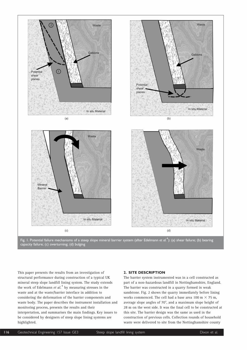
(d) Various potential failure mechanisms were predicted
resulting from the magnitude of deformations required for
equilibrium between the barrier and waste body to be
reached (Fig. 1).
It was concluded from this study that stability (i.e. ultimate
limit state) and integrity (i.e. serviceability limit state) must be
examined for each barrier design separately, and should be
checked by appropriate in-situ measurements. Despite this
recommendation, and evidence that problems have occurred as
a result of movements in steep slope lining systems,1up to
now very few—if any—barriers have been instrumented in the
UK in order to confirm acceptable structural performance.
Geotechnical Engineering 157 Issue GE3 Dixon et al. 115Steep slope landfill lining system
This paper presents the results from an investigation of
structural performance during construction of a typical UK
mineral steep slope landfill lining system. The study extends
the work of Edelmann et al.4by measuring stresses in the
waste and at the waste/barrier interface in addition to
considering the deformation of the barrier components and
waste body. The paper describes the instrument installation and
monitoring process, presents the results and their
interpretation, and summarises the main findings. Key issues to
be considered by designers of steep slope lining systems are
highlighted.
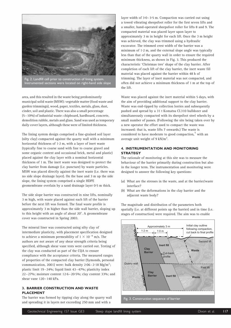
2. SITE DESCRIPTION
The barrier system instrumented was in a cell constructed as
part of a non-hazardous landfill in Nottinghamshire, England.
The barrier was constructed in a quarry formed in weak
sandstone. Fig. 2 shows the quarry immediately before lining
works commenced. The cell had a base area 100 m 3 75 m,
average slope angles of 708, and a maximum slope height of
28 m on the west side. It was the final cell to be constructed at
this site. The barrier design was the same as used in the
construction of previous cells. Collection rounds of household
waste were delivered to site from the Nottinghamshire county
(a) (b)
(c) (d)
Waste
Gabions
1
2
Potentialshearplanes
In situ Material
Waste
MineralBarrier
In situ Material In situ Material
Waste
In situ Material
Potentialshearplanes
Gabions
Waste
Fig. 1. Potential failure mechanisms of a steep slope mineral barrier system (after Edelmann et al.4): (a) shear failure; (b) bearing
capacity failure; (c) overturning; (d) bulging
Geotechnical Engineering 157 Issue GE3 Dixon et al.116 Steep slope landfill lining system
area, and this resulted in the waste being predominantly
municipal solid waste (MSW): vegetable matter (food waste and
garden trimmings), wood, paper, textiles, metals, glass, dust,
cinder, soil and plastic. There was also a small percentage
(5–10%) of industrial waste: chipboard, hardboard, concrete,
demolition rubble, metals and glass. Sand was used as temporary
daily cover layers, although these were of limited thickness.
The lining system design comprised a fine-grained soil layer
(silty clay) compacted against the quarry wall with a minimum
horizontal thickness of 1.2 m, with a layer of inert waste
(typically fine to coarse sand with fine to coarse gravel and
some organic content and occasional brick, metal and plastic)
placed against the clay layer with a nominal horizontal
thickness of 1 m. The inert waste was designed to protect the
clay barrier from damage (i.e. puncture) by waste particles.
MSW was placed directly against the inert waste (i.e. there was
no side slope drainage layer). On the base and 3 m up the side
slope, the lining system comprised a single HDPE
geomembrane overlain by a sand drainage layer 0.5 m thick.
The side slope barrier was constructed in nine lifts, nominally
3 m high, with waste placed against each lift of the barrier
before the next lift was formed. The final waste profile is
approximately 3 m higher than the side wall barrier, sloping up
to this height with an angle of about 208. A geomembrane
cover was constructed in Spring 2003.
The mineral liner was constructed using silty clay of
intermediate plasticity, with placement specification designed
to achieve a minimum permeability of 1 3 10�9 m/s. The
authors are not aware of any shear strength criteria being
specified, although shear vane tests were carried out. Testing of
the clay was conducted as part of the CQA to ensure
compliance with the acceptance criteria. The measured ranges
of properties of the compacted clay barrier (Symonds, personal
communication, 2001) were: bulk density 2.06–2.18 Mg/m3;
plastic limit 19–24%; liquid limit 43–47%; plasticity index
22–27%; moisture content 12.6–20.5%; clay content 33%; and
shear vane 120–140 kPa.
3. BARRIER CONSTRUCTION AND WASTE
PLACEMENT
The barrier was formed by tipping clay along the quarry wall
and spreading it in layers not exceeding 250 mm and with a
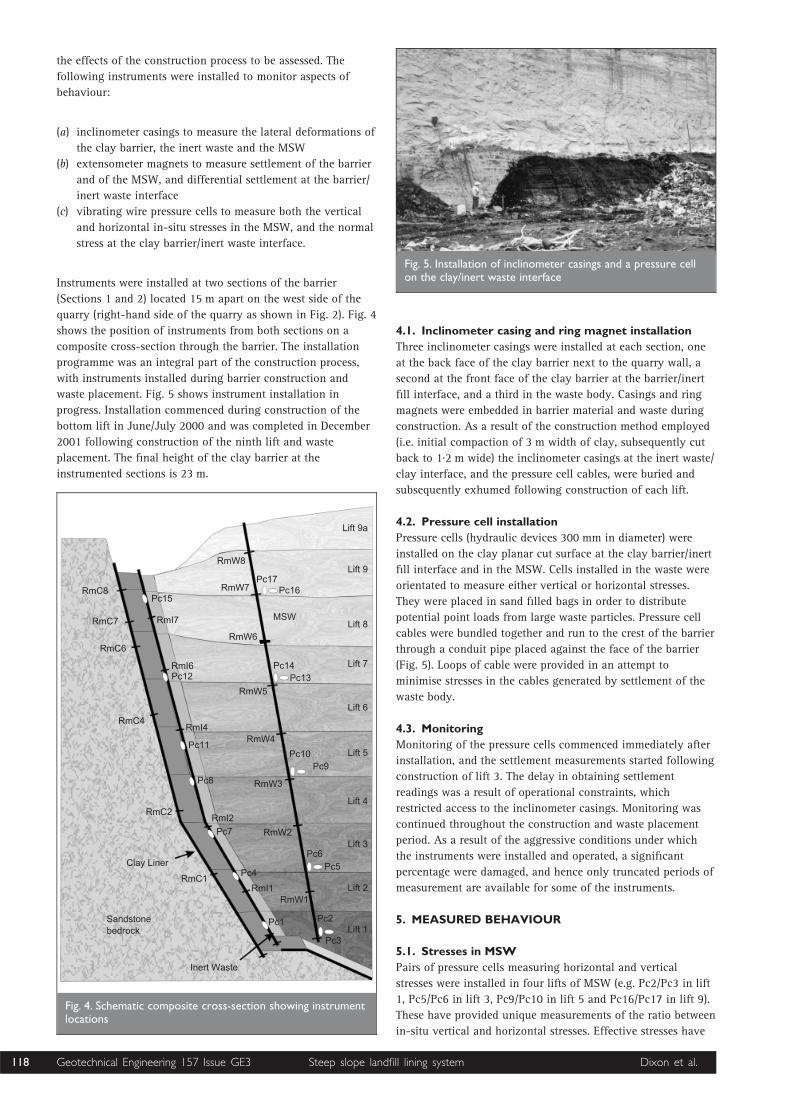
layer width of 3.0–3.5 m. Compaction was carried out using
a towed vibrating sheepsfoot roller for the first seven lifts and
a smaller, hand-operated sheepsfoot roller for lifts 8 and 9. The
compacted material was placed layer upon layer to
approximately 3 m in height for each lift. Once the 3 m height
was achieved, the clay was trimmed using a hydraulic
excavator. The trimmed crest width of the barrier was a
minimum of 1.2 m, and the external slope angle was typically
less than that of the quarry wall in order to ensure the required
minimum thickness, as shown in Fig. 3. This produced the
characteristic ‘Christmas tree’ shape of the clay barrier. After
completion of each lift of the clay barrier, the inert waste fill
material was placed against the barrier within 48 h of
trimming. The layer of inert material was not compacted, and
often did not achieve a minimum thickness of 1 m at the top of
the lift.
Waste was placed against the inert material within 5 days, with
the aim of providing additional support to the clay barrier.
Waste was end-tipped by collection lorries and subsequently
pushed and spread by a 31 t Komatsu CL310 bulldozer and
simultaneously compacted with its sheepsfoot steel wheels by a
small number of passes. (Following the site being taken over by
a new operator the effort used to compact the waste was
increased: that is, waste lifts 7 onwards.) The waste is
considered to have moderate to good compaction,5with an
average unit weight of 9 kN/m3.
4. INSTRUMENTATION AND MONITORING
STRATEGY
The rationale of monitoring at this site was to measure the
behaviour of the barrier primarily during construction but also
in the longer term. The instrumentation and monitoring were
designed to answer the following key questions:
(a) What are the stresses in the waste, and at the barrier/waste
interface?
(b) What are the deformations in the clay barrier and the
adjacent waste body?
The magnitude and distribution of the parameters both
spatially (i.e. at different points up the barrier) and in time (i.e.
stages of construction) were required. The aim was to enable
Fig. 2. Landfill cell prior to construction of lining system.Instrumented sections were located on right-hand side slope
Waste
Inert fill
Approximately 3 m
1·2 m 1·0 m
Initial clay outlinefollowing compaction,cut back to final profile
Second lift
Cut-backprofile
First lift
WasteInert fillClayBarrier
ClayBarrier
Quarry wall
Fig. 3. Construction sequence of barrier
Geotechnical Engineering 157 Issue GE3 Dixon et al. 117Steep slope landfill lining system
the effects of the construction process to be assessed. The
following instruments were installed to monitor aspects of
behaviour:
(a) inclinometer casings to measure the lateral deformations of
the clay barrier, the inert waste and the MSW
(b) extensometer magnets to measure settlement of the barrier
and of the MSW, and differential settlement at the barrier/
inert waste interface
(c) vibrating wire pressure cells to measure both the vertical
and horizontal in-situ stresses in the MSW, and the normal
stress at the clay barrier/inert waste interface.
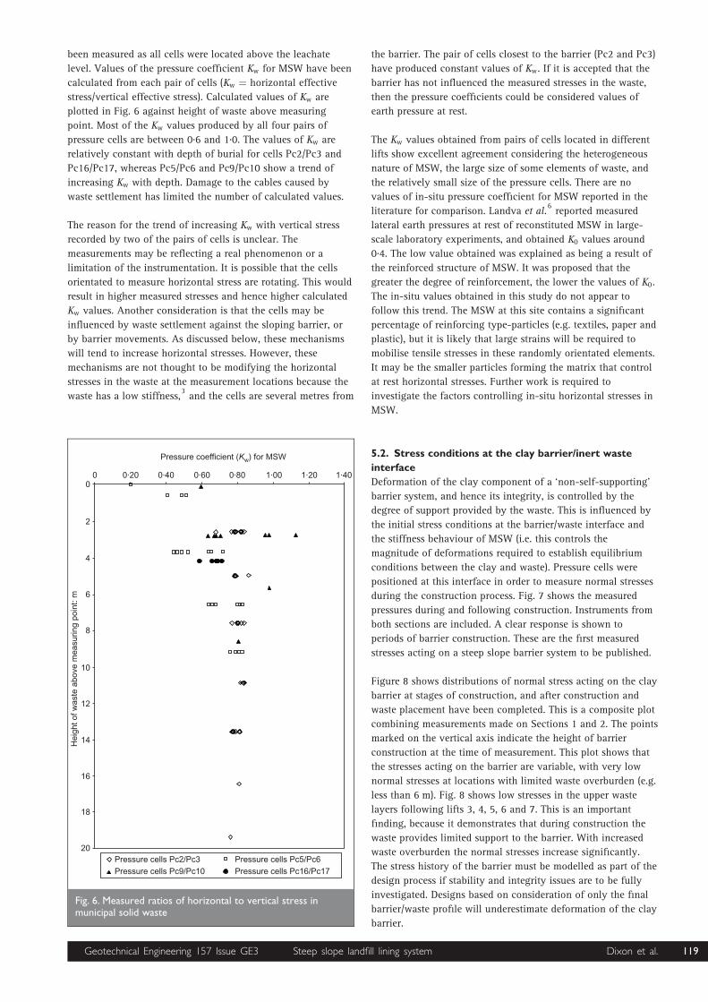
Instruments were installed at two sections of the barrier
(Sections 1 and 2) located 15 m apart on the west side of the
quarry (right-hand side of the quarry as shown in Fig. 2). Fig. 4
shows the position of instruments from both sections on a
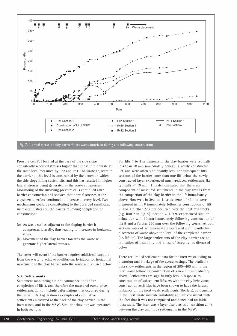
composite cross-section through the barrier. The installation
programme was an integral part of the construction process,
with instruments installed during barrier construction and
waste placement. Fig. 5 shows instrument installation in
progress. Installation commenced during construction of the
bottom lift in June/July 2000 and was completed in December
2001 following construction of the ninth lift and waste
placement. The final height of the clay barrier at the
instrumented sections is 23 m.
4.1. Inclinometer casing and ring magnet installation
Three inclinometer casings were installed at each section, one
at the back face of the clay barrier next to the quarry wall, a
second at the front face of the clay barrier at the barrier/inert
fill interface, and a third in the waste body. Casings and ring
magnets were embedded in barrier material and waste during
construction. As a result of the construction method employed
(i.e. initial compaction of 3 m width of clay, subsequently cut
back to 1.2 m wide) the inclinometer casings at the inert waste/
clay interface, and the pressure cell cables, were buried and
subsequently exhumed following construction of each lift.
4.2. Pressure cell installation
Pressure cells (hydraulic devices 300 mm in diameter) were
installed on the clay planar cut surface at the clay barrier/inert
fill interface and in the MSW. Cells installed in the waste were
orientated to measure either vertical or horizontal stresses.
They were placed in sand filled bags in order to distribute
potential point loads from large waste particles. Pressure cell
cables were bundled together and run to the crest of the barrier
through a conduit pipe placed against the face of the barrier
(Fig. 5). Loops of cable were provided in an attempt to
minimise stresses in the cables generated by settlement of the
waste body.
4.3. Monitoring
Monitoring of the pressure cells commenced immediately after
installation, and the settlement measurements started following
construction of lift 3. The delay in obtaining settlement
readings was a result of operational constraints, which
restricted access to the inclinometer casings. Monitoring was
continued throughout the construction and waste placement
period. As a result of the aggressive conditions under which
the instruments were installed and operated, a significant
percentage were damaged, and hence only truncated periods of
measurement are available for some of the instruments.
5. MEASURED BEHAVIOUR
5.1. Stresses in MSW
Pairs of pressure cells measuring horizontal and vertical
stresses were installed in four lifts of MSW (e.g. Pc2/Pc3 in lift
1, Pc5/Pc6 in lift 3, Pc9/Pc10 in lift 5 and Pc16/Pc17 in lift 9).
These have provided unique measurements of the ratio between
in-situ vertical and horizontal stresses. Effective stresses have
Lift 9a
Lift 9
Lift 8
Lift 7
RmW8
RmW7
RmW6
RmW5
Lift 6
Pc17Pc16
MSW
Pc14Pc13
Pc10Pc9
Lift 5
RmW4
RmW3
RmW2
Lift 4
Lift 3Pc6
Pc5
Lift 2
Lift 1Pc2
Pc3
Inert Waste
Sandstonebedrock
RmC1
Clay Liner
RmC2
Pc1
RmW1RmI1
Pc4
Pc7
RmI2
Pc8
Pc11
RmI4RmC4
Pc12RmI6
RmC6
RmI7RmC7
RmC8Pc15
Fig. 4. Schematic composite cross-section showing instrumentlocations
Fig. 5. Installation of inclinometer casings and a pressure cellon the clay/inert waste interface
Geotechnical Engineering 157 Issue GE3 Dixon et al.118 Steep slope landfill lining system
been measured as all cells were located above the leachate
level. Values of the pressure coefficient Kw for MSW have been
calculated from each pair of cells (Kw ¼ horizontal effective
stress/vertical effective stress). Calculated values of Kw are
plotted in Fig. 6 against height of waste above measuring
point. Most of the Kw values produced by all four pairs of
pressure cells are between 0.6 and 1.0. The values of Kw are
relatively constant with depth of burial for cells Pc2/Pc3 and
Pc16/Pc17, whereas Pc5/Pc6 and Pc9/Pc10 show a trend of
increasing Kw with depth. Damage to the cables caused by
waste settlement has limited the number of calculated values.
The reason for the trend of increasing Kw with vertical stress
recorded by two of the pairs of cells is unclear. The
measurements may be reflecting a real phenomenon or a
limitation of the instrumentation. It is possible that the cells
orientated to measure horizontal stress are rotating. This would
result in higher measured stresses and hence higher calculated
Kw values. Another consideration is that the cells may be
influenced by waste settlement against the sloping barrier, or
by barrier movements. As discussed below, these mechanisms
will tend to increase horizontal stresses. However, these
mechanisms are not thought to be modifying the horizontal
stresses in the waste at the measurement locations because the
waste has a low stiffness,3and the cells are several metres from
the barrier. The pair of cells closest to the barrier (Pc2 and Pc3)
have produced constant values of Kw. If it is accepted that the
barrier has not influenced the measured stresses in the waste,
then the pressure coefficients could be considered values of
earth pressure at rest.
The Kw values obtained from pairs of cells located in different
lifts show excellent agreement considering the heterogeneous
nature of MSW, the large size of some elements of waste, and
the relatively small size of the pressure cells. There are no
values of in-situ pressure coefficient for MSW reported in the
literature for comparison. Landva et al.6reported measured
lateral earth pressures at rest of reconstituted MSW in large-
scale laboratory experiments, and obtained K0 values around
0.4. The low value obtained was explained as being a result of
the reinforced structure of MSW. It was proposed that the
greater the degree of reinforcement, the lower the values of K0.
The in-situ values obtained in this study do not appear to
follow this trend. The MSW at this site contains a significant
percentage of reinforcing type-particles (e.g. textiles, paper and
plastic), but it is likely that large strains will be required to
mobilise tensile stresses in these randomly orientated elements.
It may be the smaller particles forming the matrix that control
at rest horizontal stresses. Further work is required to
investigate the factors controlling in-situ horizontal stresses in
MSW.
5.2. Stress conditions at the clay barrier/inert waste
interface
Deformation of the clay component of a ‘non-self-supporting’
barrier system, and hence its integrity, is controlled by the
degree of support provided by the waste. This is influenced by
the initial stress conditions at the barrier/waste interface and
the stiffness behaviour of MSW (i.e. this controls the
magnitude of deformations required to establish equilibrium
conditions between the clay and waste). Pressure cells were
positioned at this interface in order to measure normal stresses
during the construction process. Fig. 7 shows the measured
pressures during and following construction. Instruments from
both sections are included. A clear response is shown to
periods of barrier construction. These are the first measured
stresses acting on a steep slope barrier system to be published.
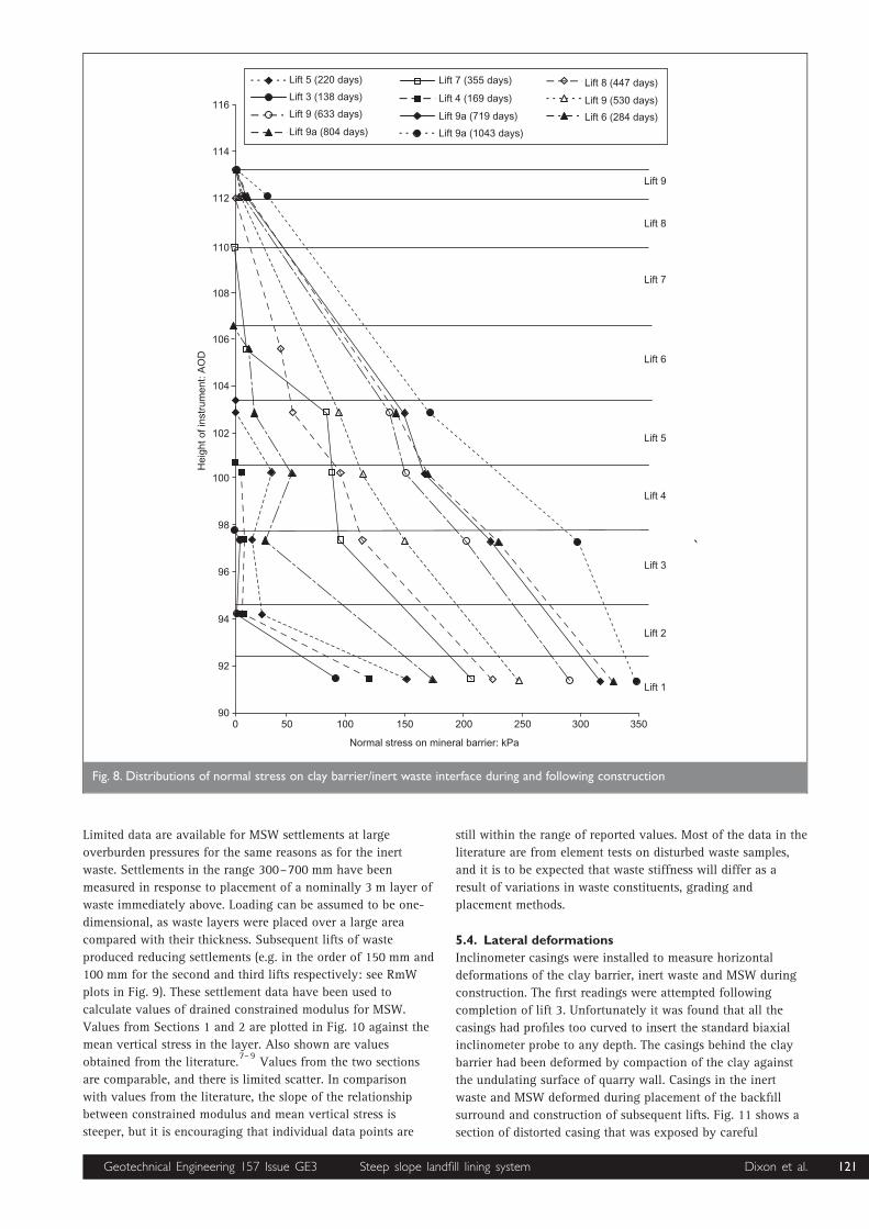
Figure 8 shows distributions of normal stress acting on the clay
barrier at stages of construction, and after construction and
waste placement have been completed. This is a composite plot
combining measurements made on Sections 1 and 2. The points
marked on the vertical axis indicate the height of barrier
construction at the time of measurement. This plot shows that
the stresses acting on the barrier are variable, with very low
normal stresses at locations with limited waste overburden (e.g.
less than 6 m). Fig. 8 shows low stresses in the upper waste
layers following lifts 3, 4, 5, 6 and 7. This is an important
finding, because it demonstrates that during construction the
waste provides limited support to the barrier. With increased
waste overburden the normal stresses increase significantly.
The stress history of the barrier must be modelled as part of the
design process if stability and integrity issues are to be fully
investigated. Designs based on consideration of only the final
barrier/waste profile will underestimate deformation of the clay
barrier.
0 0·20 0·40 0·60 0·80 1·00 1·20 1·40
Pressure coefficient (Kw) for MSW
0
2
4
6
8
10
12
14
16
18
20
Hei
ght o
f was
te a
bove
mea
surin
g po
int:
m
Pressure cells Pc2/Pc3
Pressure cells Pc9/Pc10
Pressure cells Pc5/Pc6
Pressure cells Pc16/Pc17
Fig. 6. Measured ratios of horizontal to vertical stress inmunicipal solid waste
Geotechnical Engineering 157 Issue GE3 Dixon et al. 119Steep slope landfill lining system
Pressure cell Pc1 located at the base of the side slope
consistently recorded stresses higher than those in the waste at
the same level measured by Pc2 and Pc3. The waste adjacent to
the barrier at this level is constrained by the bench on which
the side slope lining system sits, and this has resulted in higher
lateral stresses being generated as the waste compresses.
Monitoring of the surviving pressure cells continued after
barrier construction and showed that normal stresses at the
clay/inert interface continued to increase at every level. Two
mechanisms could be contributing to the observed significant
increases in stress on the barrier following completion of
construction:
(a) As waste settles adjacent to the sloping barrier it
compresses laterally, thus leading to increases in horizontal
stress.
(b) Movement of the clay barrier towards the waste will
generate higher lateral stresses.
The latter will occur if the barrier requires additional support
from the waste to achieve equilibrium. Evidence for horizontal
movement of the clay barrier into the waste is discussed below.
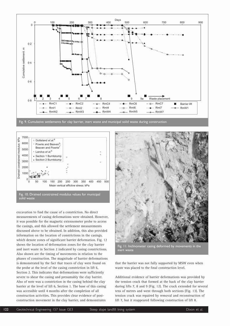
5.3. Settlements
Settlement monitoring did not commence until after
completion of lift 3, and therefore the measured cumulative
settlements do not include deformations that occurred during
the initial lifts. Fig. 9 shows examples of cumulative
settlements measured at the back of the clay barrier, in the
inert waste, and in the MSW. Similar behaviour was measured
in both sections.
For lifts 1 to 8 settlements in the clay barrier were typically
less than 50 mm immediately beneath a newly constructed
lift, and were often significantly less. For subsequent lifts,
sections of the barrier more than one lift below the newly
constructed layer experienced much-reduced settlements (i.e.
typically , 10 mm). This demonstrated that the main
component of measured settlements in the clay results from
the compaction of the clay barrier in the lift immediately
above. However, in Section 1, settlements of 43 mm were
measured in lift 8 immediately following construction of lift
9, and a further 270 mm occurred over the next few weeks
(e.g. RmC7 in Fig. 9). Section 2, Lift 9, experienced similar
behaviour, with 80 mm immediately following construction of
lift 9 and a further 350 mm over the following weeks. At both
sections rates of settlement were decreased significantly by
placement of waste above the level of the completed barrier
(i.e. lift 9a). The large settlements of the clay barrier are an
indication of instability and a loss of integrity, as discussed
below.
There are limited settlement data for the inert waste owing to
distortion and blockage of the access casings. The available
data show settlements in the region of 200–400 mm in the
inert waste following construction of a new lift immediately
above. Settlements are significantly less in response to
construction of subsequent lifts. As with the clay behaviour,
construction activities have been shown to have the largest
influence on the inert waste settlements. The large settlements
in the inert waste indicate instability and are consistent with
the fact that it was not compacted and hence had an initial
loose state. The inert waste layer also acts as a transition zone
between the clay and large settlements in the MSW.
400
350
300
250
200
150
100
50
00 100 200 300 400 500 600 700 800 900 1000 1100
Pc11 Section 1
Pc4 Section2
Pc1 Section 1
Construction of lift of MSW
Pc8 Section 2
Pc7 Section 1
Pc15 Section 1
Pc12 Section 2
Days
Pre
ssur
e: k
Pa
3 4 5 6 7 8 9 9a Waste placement1 2
Fig. 7. Normal stress on clay barrier/inert waste interface during and following construction
Geotechnical Engineering 157 Issue GE3 Dixon et al.120 Steep slope landfill lining system
Limited data are available for MSW settlements at large
overburden pressures for the same reasons as for the inert
waste. Settlements in the range 300–700 mm have been
measured in response to placement of a nominally 3 m layer of
waste immediately above. Loading can be assumed to be one-
dimensional, as waste layers were placed over a large area
compared with their thickness. Subsequent lifts of waste
produced reducing settlements (e.g. in the order of 150 mm and
100 mm for the second and third lifts respectively: see RmW
plots in Fig. 9). These settlement data have been used to
calculate values of drained constrained modulus for MSW.
Values from Sections 1 and 2 are plotted in Fig. 10 against the
mean vertical stress in the layer. Also shown are values
obtained from the literature.7– 9
Values from the two sections
are comparable, and there is limited scatter. In comparison
with values from the literature, the slope of the relationship
between constrained modulus and mean vertical stress is
steeper, but it is encouraging that individual data points are
still within the range of reported values. Most of the data in the
literature are from element tests on disturbed waste samples,
and it is to be expected that waste stiffness will differ as a
result of variations in waste constituents, grading and
placement methods.
5.4. Lateral deformations
Inclinometer casings were installed to measure horizontal
deformations of the clay barrier, inert waste and MSW during
construction. The first readings were attempted following
completion of lift 3. Unfortunately it was found that all the
casings had profiles too curved to insert the standard biaxial
inclinometer probe to any depth. The casings behind the clay
barrier had been deformed by compaction of the clay against
the undulating surface of quarry wall. Casings in the inert
waste and MSW deformed during placement of the backfill
surround and construction of subsequent lifts. Fig. 11 shows a
section of distorted casing that was exposed by careful
Lift 5 (220 days)
Lift 3 (138 days)
Lift 9 (633 days)
Lift 9a (804 days)
Lift 7 (355 days)
Lift 4 (169 days)
Lift 9a (719 days)
Lift 9a (1043 days)
Lift 8 (447 days)
Lift 9 (530 days)
Lift 6 (284 days)116
114
112
110
108
106
104
102
100
98
96
92
94
90
Hei
ght o
f ins
trum
ent:
AO
D
0 50 100 150 200 250 300 350
Normal stress on mineral barrier: kPa
Lift 1
Lift 2
Lift 3
Lift 4
Lift 5
Lift 6
Lift 7
Lift 8
Lift 9
Fig. 8. Distributions of normal stress on clay barrier/inert waste interface during and following construction
Geotechnical Engineering 157 Issue GE3 Dixon et al. 121Steep slope landfill lining system
excavation to find the cause of a constriction. No direct
measurements of casing deformations were obtained. However,
it was possible for the magnetic extensometer probe to access
the casings, and this allowed the settlement measurements
discussed above to be obtained. In addition, this also provided
information on the location of constrictions in the casings,
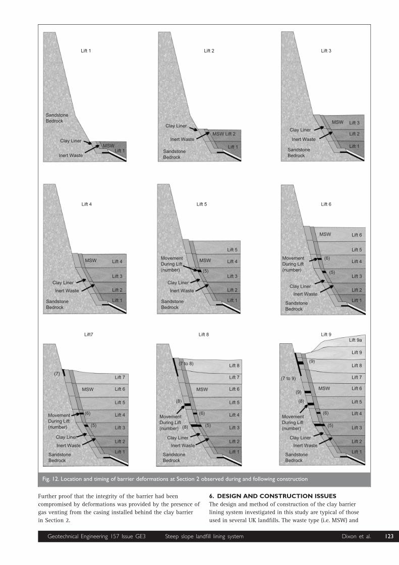
which denote zones of significant barrier deformation. Fig. 12
shows the location of deformation zones for the clay barrier
and inert waste in Section 2 indicated by casing constrictions.
Also shown are the timing of movements in relation to the
phases of construction. The magnitude of barrier deformations
is demonstrated by the fact that traces of clay were found on
the probe at the level of the casing constriction in lift 6,
Section 2. This indicates that deformations were sufficiently
severe to shear the casing and presumably the clay barrier.
Also of note was a constriction in the casing behind the clay
barrier at the level of lift 6, Section 1. The base of this casing
was accessible until 4 months after the completion of all
construction activities. This provides clear evidence of post-
construction movement in the clay barrier, and demonstrates
that the barrier was not fully supported by MSW even when
waste was placed to the final construction level.
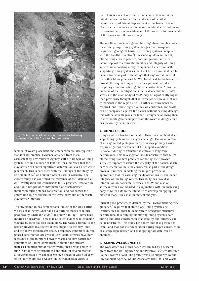
Additional evidence of barrier deformations was provided by
the tension crack that formed at the back of the clay barrier
during lifts 7, 8 and 9 (Fig. 12). The crack extended for several
tens of metres and went through both sections (Fig. 13). The
tension crack was repaired by removal and reconstruction of
lift 7, but it reappeared following construction of lift 8.
900700 80060050040030020010000
0·2
0·4
0·6
0·821 3 4 5 6 7 8 9 9a Waste placement
Days
RmC1
RmI1
RmW2
RmC2
RmI2RmW3
RmC4
RmI4
RmW4
RmC6
RmI6
RmW5
RmC7
RmI7
RmW7
Barrier lift
RmW1
Cum
ulat
ive
settl
emen
t: m
Fig. 9. Cumulative settlements for clay barrier, inert waste and municipal solid waste during construction
7000
6000
5000
4000
3000
2000
1000
0Dra
ined
con
stra
ined
mod
ulus
: kP
a
0 50 100 150 200 250 300 350 400 450 500
Mean vertical effictive stress: kPa
Gotteland et al.8
Powrie and Beaven9;Beaven and Powrie7
Landva et al.6
Section 1 BurntstumpSection 2 Burntstump
Fig. 10. Drained constrained modulus values for municipalsolid waste
Fig. 11. Inclinometer casing deformed by movements in theinert waste
Geotechnical Engineering 157 Issue GE3 Dixon et al.122 Steep slope landfill lining system
Further proof that the integrity of the barrier had been
compromised by deformations was provided by the presence of
gas venting from the casing installed behind the clay barrier
in Section 2.
6. DESIGN AND CONSTRUCTION ISSUES
The design and method of construction of the clay barrier
lining system investigated in this study are typical of those
used in several UK landfills. The waste type (i.e. MSW) and
Lift 1
SandstoneBedrock
Clay Liner
Inert Waste
MSWLift 1
Lift 2
Clay Liner
Inert Waste
SandstoneBedrock
MSW Lift 2
Lift 1
Lift 3
Clay Liner
Inert Waste
SandstoneBedrock
Lift 1
Lift 2
MSW Lift 3
Lift 6
MSW Lift 6
Lift 5
Lift 4
Lift 3
Lift 2
Lift 1
(6)
(5)
MovementDuring Lift(number)
Clay Liner
Inert Waste
SandstoneBedrock
Lift 5
MSW
Lift 5
Lift 4
Lift 3
Lift 2
Lift 1
(5)
MovementDuring Lift(number)
Clay Liner
Inert Waste
SandstoneBedrock
Lift 4
MSW Lift 4
Lift 3
Lift 2
Lift 1
Clay Liner
Inert Waste
SandstoneBedrock
Lift 9
MSW Lift 6
Lift 5
Lift 4
Lift 3
Lift 2
Lift 1
(6)
(5)
MovementDuring Lift(number)
Clay Liner
Inert Waste
SandstoneBedrock
(7 to 9)
(9)
(9)
(8)
Lift 7
Lift 8
Lift 9
Lift 9aLift 8
Lift 6
Lift 5
Lift 4
Lift 3
Lift 2
Lift 1
(6)
(5)
MovementDuring Lift(number)
Clay Liner
Inert Waste
SandstoneBedrock
(7 to 8)
(8)
(8)
Lift 7
Lift 8
MSW
Lift7
Lift 6
Lift 5
Lift 4
Lift 3
Lift 2
Lift 1
(6)
(5)
MovementDuring Lift(number)
Clay Liner
Inert Waste
SandstoneBedrock
(7)Lift 7
MSW
Fig. 12. Location and timing of barrier deformations at Section 2 observed during and following construction
Geotechnical Engineering 157 Issue GE3 Dixon et al. 123Steep slope landfill lining system
method of waste placement and compaction are also typical of
standard UK practice. Evidence obtained from visual
assessment by Environment Agency staff of this type of lining
system used in a number of landfills1has indicated that the
clay barrier can suffer significant deformation, even after waste
placement. This is consistent with the findings of the study by
Edelmann et al.4of a similar system used in Germany. The
current study has confirmed the relevance of the Edelmann et
al.4investigation and conclusions to UK practice. However, in
addition it has provided information on waste/barrier
interaction during staged construction, and has shown the
controlling role of stresses in the waste body and at the waste/
clay barrier interface.
This investigation has demonstrated failure of the clay barrier
via loss of integrity. Shear and overturning modes of failure
predicted by Edelmann et al.,4and shown in Fig. 1, have been
inferred or observed. There is insufficient evidence to conclude
whether bulging has also taken place. The waste adjacent to the
barrier provides insufficient lateral support to the clay liner,
and the above mechanisms result. Temporary conditions during
phased construction are critical. Low lateral stresses have been
measured at the interface between waste and clay barrier for
conditions of limited overburden. Although the stresses
increased significantly at higher overburden depths and with
time, clay barrier deformations continued for several months
after completion of waste placement. Stresses in waste adjacent
to the barrier are low because limited compaction effort is
used. This is a result of concern that compaction activities
might damage the barrier. In the absence of detailed
measurements of lateral displacement of the barrier it is not
clear whether the measured increases in lateral stress following
construction are due to settlement of the waste or to movement
of the barrier into the waste body.
The results of this investigation have significant implications
for all steep slope lining system designs that incorporate
engineered geological barriers (i.e. lining systems compliant
with the Landfill Directive2). Present-day MSW in the UK,
placed using current practice, does not provide sufficient
lateral support to ensure the stability and integrity of lining
systems incorporating a clay component. Hence ‘non-self-
supporting’ lining systems should not be used unless it can be
demonstrated as part of the design that engineered material
(i.e. either fill or processed MSW) placed next to the barrier will
provide the required support. The design must consider
temporary conditions during phased construction. A positive
outcome of the investigation is the evidence that horizontal
stresses in the main body of MSW may be significantly higher
than previously thought—that is, earth (waste) pressure at rest
coefficients in the region of 0.8. Further measurements are
required, but if these higher values are confirmed, and waste
can be compacted against the barrier without causing damage,
this will be advantageous for landfill designers, allowing them
to incorporate greater support from the waste in designs than
has previously been the case.10
7. CONCLUSIONS
Design and construction of Landfill Directive compliant steep
slope lining systems are a major challenge. The incorporation
of an engineered geological barrier, or clay primary barrier,
requires rigorous assessment of the support conditions.
Behaviour during construction is critical to long-term
performance. This investigation has demonstrated that MSW
placed using standard practices cannot by itself provide
sufficient support to ensure the integrity of the barrier. Waste/
barrier interaction must be considered as part of the design
process. Numerical modelling techniques provide an
appropriate tool for assessing the deformations in, and hence
integrity of, the lining system. This study has provided
information on horizontal stresses in MSW and also on
stiffness, which can be used in conjunction with the increasing
body of MSW data in the literature to develop an appropriate
material model for use in numerical analyses.
Current good practice, as defined by the Environment Agency
guidance,1requires that steep slope lining systems be
instrumented in order to demonstrate acceptable structural
performance. It is only by monitoring lining systems both
during and after construction that stability and integrity can
be demonstrated. This study has shown that it is possible to
install and monitor instrumentation during staged construction
of a steep slope barrier, and that appropriate data can be
obtained.
8. ACKNOWLEDGEMENTS
The work described in this paper was funded by a research
grant from the UK Engineering and Physical Sciences Research
Council (GR/M33570). The project was also supported by the
Environment Agency, Golder Associates (UK) Ltd, and Waste
Fig. 13. Tension crack at back of clay barrier followingconstruction of lift 9, caused by overturning
Geotechnical Engineering 157 Issue GE3 Dixon et al.124 Steep slope landfill lining system
Recycling Group. Special thanks are due to Andrew Connell for
his help with installing the instruments and the production of
Fig. 10.
REFERENCES
1. JONES D. R. V. and DIXON N. Stability of Landfill Lining
Systems: Literature Review. Environment Agency, 2003,
Research and Development Project P1-385, Report 1.
2. COUNCIL OF THE EUROPEAN UNION. Council Directive of 26
April 1999 on the landfill of waste (1999/31/EC).
Official Journal of the European Communities, 1999,
L182/1.
3. DIXON N., JONES D. R. V. and WHITTLE R. Mechanical
properties of household waste: In situ assessment using
pressuremeters. Proceedings of the 7th International Waste
Management and Landfill Symposium, Sardinia, 1999,
453–460.
4. EDELMANN L., HERTWECK M. and AMANN A. D. Mechanical
behaviour of landfill barrier systems. Proceedings of the
Institution of Civil Engineers—Geotechnical Engineering,
1999, 137, 215–224.
5. FASSETT J. B., LEONARDO G. A. and REPETTO P. C.
Geotechnical properties of municipal solid waste and their
use in landfill design. Proceedings of the Waste Technical
Conference–Landfill Technology, National Solid Waste
Management Association, Charleston, SC, 1994, 1–29.
6. LANDVA A. O., VALSANGKAR A. J. and PELKEY S. G. Lateral
earth pressure at rest and compressibility of municipal
solid waste. Canadian Geotechnical Journal, 2000, 37,
1157–1165.
7. BEAVEN R. P. and POWRIE W. Hydrological and geotechnical
properties of refuse using a large scale compression cell.
Proceedings of the 5th International Landfill Symposium,
Sardinia, 1995, 745–760.
8. GOTTELAND P., GACHET C. and VUILLEMIN M. Mechanical
study of a municipal solid waste landfill. Proceedings of the
8th International Waste Management and Landfill
Symposium, Sardinia, 2001, 424–433.
9. POWRIE W. and BEAVEN R. P. Hydraulic properties of
household waste and implications for landfills. Proceedings
of the Institution of Civil Engineers—Geotechnical
Engineering, 1999, 137, 235–247.
10. JONES D. R. V. and DIXON N. The long term stability of
landfill side slopes. Proceedings of the 6th International
Waste Management and Landfill Symposium, Sardinia,
1997, 3, 517–523.
Please email, fax or post your discussion contributions to the secretary: email: [email protected]; fax: þ44 (0)20 665 2294;
or post to Mary Henderson, Journals Department, Institution of Civil Engineers, 1–7 Great George Street, London SW1P 3AA.
Geotechnical Engineering 157 Issue GE3 Dixon et al. 125Steep slope landfill lining system