structural system—standard oil of indiana building are about 3,000,000 sq ft of floor area in the...
TRANSCRIPT

structural System—Standard Oil of Indiana Building E. ALFRED PICARDI
T H I S PAPER, which documents the structural design of the
Standard Oil of Indiana Building in Chicago, 111., is presented for several reasons. First, the building is one of the world's tallest—for a while, the second or third highest. Second, and perhaps of most importance, the structural concept is unique. I t incorporates innovations in both design concepts and details that have resulted in economy in the total building cost by reducing tonnage of steel used in the structural frame, by simplifying fabrication techniques, and by speeding the erection process. Furthermore, the structural concept provides for incorporation of the supply ducts and piping for the mechanical system within the same volume as the structure, furthering economy of the building.
The building is under construction on the Chicago Lakefront on a site measuring 350 ft by 385 ft immediately east of the Prudential Tower, bounded on the south by Randolf St., on the north by Lake St., on the west by Stetson Ave., and on the east by Columbus Dr.
The building project consists of a base structure extending five levels below a plaza, covering the entire site, and a tower structure extending through and 82 stories above the plaza, covering approximately 2 6 % of the site. There are about 3,000,000 sq ft of floor area in the tower and an additional 500,000 sq ft of floor area below the plaza surrounding the tower. The tower height above the plaza is 1,123 ft and height above the lowest basement is 1.179 ft. The plaza is at El. 55 CCD and the lowest basement is at El. —13 CCD. The grade of the site at the lowest street level is El. 8 CCD. (CCD refers to Chicago City Da tum; 0.00 CCD is the mean high water level of Lake Michigan, approximately 578 ft above mean tide at New York Harbor. All elevations are in feet.)
The Standard Oil Building will be among the world's tallest structures. Its height compared with other tall buildings elsewhere is shown in Fig. 1.
E. AlfredPicardiisSenior Vice President and Director^ Perkins & Will Corp., Washington, B.C.
This paper is reprinted from the Journal of the Structural Division, ASCE, Vol. 99, No. ST4, April, 7973.
Two other papers^'^ document the computer techniques used in the structural analysis of the building and consider several miscellaneous structural problems encountered in the design of the building that are unique to its particular concept.
STRUCTURAL SYSTEM
Concept Development—In the development of the structural concepts for this building, the then current methods of design and available construction techniques were examined in a search for the most economical yet safe systems available from existing technology. Most high-rise structures have been designed as frames consisting of vertical columns, usually arranged on a grid system, and beams and girders spanning between columns. These frames resist lateral loads by various girder-to-column moment connections, aided if necessary by vertical trusses within the central core of the building, or by various types of knee or portal braces. Under lateral loads, e.g., wind, the frame distorts laterally as a combination of cantilever bending due to shortening of the leeward columns and lengthening of windward columns, plus a drift between each restrained floor level, causing an S curve in the column between floors.
In framed buildings, if bracing systems could be designed to minimize or eliminate the floor-to-floor column drift so that the tower would bend essentially as a canti-levered beam, considerable savings in material for any predetermined acceptable total tower drift could be realized. If the bracing system could also contribute to the gravity load-carrying capability of the frame rather than just acting as a stiff'ener, then further economy of material can be achieved.
The 100-story John Hancock Building in Chicago^ is perhaps the best example of a frame designed to perform under lateral load very similar to a cantilevered beam. The X-bracing in the four sides of the perimeter frame causes the entire tower to behave under lateral load in this manner. In addition, the inclined braces carry their fair share of gravity loads. The average structural steel weight for the Hancock Tower is about 31 psf. This is about the same average steel weight of earlier conven-
42
E N G I N E E R I N G J 0 U R N A L / A M E R I C A N I N S T I T U T E OF STEEL C O N S T R U C T I O N

1500 FEET
1200 FEET
900 FEET
600 FEET
300 FEET
JOHN HANCOCK CENTER CHICAGO
1105 FEET
STANDARD OIL CHICAGO
1125 FEET
EMPIRE STATE NEW YORK 1250 FEET
V.ORI.D TRADE CENTER NEW YORK 1350 FEET
SEARS
1450 FEET
Fig. 1. Comparison of world^s tallest buildings
tional frames in the 30-story to 60-story height range. Certainly, the cantilevered tube concept was the first choice for the Standard Oil of Indiana Building.
Recognizing the great efficiency of the Hancock Tower design in terms of tonnage of steel, attempts were made to improve on this concept, to introduce further economy. Would it be possible to develop a structural system with efficient tube action, yet simplify the fabrication and erection problems to introduce further economy? A natural concept to consider would be an arrangement of steel plate walls with openings only large enough to accommodate architecturally acceptable vision panels. Thus, the steel would be distributed continuously around the perimeter walls, rather than in intermittent heavy column, spandrel, and bracing members. This is the concept which was adopted as a goal. I t is described in the following sections.
Basic Structure—To carry the heavy vertical loads, the plates in the exterior wall were arranged in a pattern as shown in Fig. 2. Thus the vertical elements consisted essentially of two plates forming two sides of a triangle and welded to other horizontal plates that served as sprandrel beams. Using this concept it was possible to develop an assemblage of plates that formed the exterior structural wall. These plates could be mass produced in large 3-story high sections in fabricating shops using automatic cutting and welding techniques. The details permitted the development of jigs and a production line arrangement for the fabrication process. Furthermore,
these large sections could be erected at the site using simple bolted connections, thereby eliminating, as much as possible, time-consuming field welding and expensive quality control procedures.
EXTERIOR 810E
SPANDREL
BOLTED SPANDREL SPLICE
- I H T E R I O R SIDE
Fig. 2. Steel plate arrangement of exterior wall
43
S E C O N D Q U A R T E R / 1 9 7 5

•^::>;a»*^::-::p;u^^^
? •;;'i:;;;;.;:
i '
f JpMii
'mmm>«m
'^
«|>W^;,:,::;i|;,i;n;ii.iii>Nii|
| , ; | ;[ > J::':i;"i-v^^
1 ••
i
"M mivk^ mMmm^^
iiyf'''\jr'''<iigt''%Jf •'^""<iig)>rf>'ii«^ m;i^"'\0f'- <%^«'%;jf' \;r/ i^^'nt^^mtH^
• • • • • • • " • ^ ^ H K 9 i ~"
- Mr m-mmm wm ^
Fig. 3. Plan, Zone A, Floors 3-79
These two factors, mass production of the wall elements using automated procedures and the use of field bolting rather than expensive welding, were of great importance to the goal of achieving economy of steel in place in the building.
The balance of the main structural system includes the framing for the central core and the floor system. Figure 3 shows the floor plan for floors 3-19, showing the central core consisting of 16 columns, the 64 exterior chevron columns, and the four re-entrant corners. The re-entrant corners were made of stiffened steel plate and served to transfer the large shear loads from one face of the building to the other, under the action of lateral loads.
Fireproofing of the exterior wall steel was accomplished by the application of Zonolite Mono-Kote IV sprayed-on cementitious material. Columns required a 4-hr rating and the thickness of fireproofing vailed from ^ - i n . to 2 ^ in. The re-entrant corner plate required 134 in. of fireproofing. The thicknesses of the sprayed-on material was determined not only by fireproofing requirements, but also by the thermal insulation requirement for the exterior chevron columns. The differential temperature between the exterior wall system and the interior core is limited to 22° F when the outside temperature is —30° F and the inside air temperature is 70° F. Special partition details for use in the upper stories were developed by the architects to avoid partition damage due to the expansion and contraction of the exterior wall.
The fireproofing rating for the beams and trusses of the floor system was 3 hr, and this was accomplished
with thicknesses of Zonolite varying from 3^-in. to 11^ in., depending upon the size and span of members.
All field connections were made with high strength A325 or A490 bolts of 1-in. or IJ/^-in. diam. The use of bolts of only two different diameters greatly simplified the bolting procedures and minimized the chances for
Floor Systems—The floor system between the central core and the exterior walls not only supports the vertical dead and live loads, but it also serves as a diaphragm to stabilize the exterior walls and to distribute wind shears from the face wall (to the wind) to the walls serving as webs of the cantilever tube acting frame. The main floor span was 45 ft, necessitating deep girders or trusses. The designer's choice was trusses, 38 in. deep overall, simply supported at either end with single shear, high strength A325 and A490 bolted connections. Figure 4 is a model of the main structural system showing the floor trusses without the decking. All trusses on a typical floor are identical except for one-half of the end panel at the ends connected to the core. This end panel is detailed to connect to either columns or core girders. Trusses are spaced 10 ft apart and are staggered on alternate floors to frame into alternate sides of the exterior vertical chevrons. The variable length corner floor beams are wide-flange sections, as are the four diagonals spanning from the corner columns of the core to the apex of the re-entrant corners.
The floor framing system of simple span rolled sections and long span deep trusses was developed to achieve maximum economy in the combined material, fabrica-
44
E N G I N E E R I N G J 0 U R N A L / A M E R I C A N I N S T I T U T E OF STEEL C O N S T R U C T I O N

SPANDREL
Fig. 4. Model of main structure {used during conceptual development)
tion, and erection cost. The 4,000 essentially identical floor trusses are mass-produced on a production line system, as are the typical diagonal beams and corner filler beams. The truss dimensions were chosen to mate with the 5-ft modular ceiling system containing lighting and air conditioning distribution systems. Furthermore, the interstitial space was used for the mechanical system, distributing and returning air from the vertical shafts in the core.
The deck is a blended system, shown in Fig. 5, consisting of 3-ft wide panels of 13/2"i^- composite 18-gage deck alternating with 2-ft wide panels of l^^-in. composite 18/20 gage cellular deck for the electrical and communication distribution systems. Topping consists of 5,000 psi lightweight concrete, 4 in. thick, over the top of the deck, making a total diaphragm thickness of 53/2 i^-
In lieu of sprayed-on fireproofing on the underside of the deck, a welded wire mesh reinforcing is installed in the concrete topping to provide load-carrying capacity of the concrete slab adequate to meet Chicago Building Code minimum live load requirements of 50 psf without the mobilization of the steel deck. This construction also meets the fireproofing requirements of the Code. The elimination of the sprayed-on fireproofing on the underside of the deck and substitution of welded wire fabric in the concrete topping afforded a substantial savings in cost of the floor system. If the steel deck is included in computing the floor load capacity, the live load capacity would be in excess of 80 psf.
Foundations—The tower is founded on caissons extending to rock, as shown in Fig. 6. There are 40 perimeter caissons supporting a transfer girder that carries the 64 chevron columns of the tube. These caissons vary from 5 ft-0 in. to 6 ft-9 in. in diameter. The 16 core columns are supported on caissons varying from 8 ft-9 in. to 10 ft-3 in. in diameter. All caissons were constructed of 6,000 psi
Fig. 5. Cross section of spandrel beams, floor trusses, and deck
concrete using a design stress of 0.3 Z'^. The maximum caisson load is 21,000 kips, and it occurs under the corner columns of the core. The wind shear of 8,300 kips is transferred from the concrete grid above the caissons into the soil as shown in Fig. 7. The mechanism of the transfer is not quite clear. However, the concrete grid or ^g^ crate is so designed and proportioned that any one or a combination of the following mechanisms can be mobilized:
1. Passive pressure between the vertical sides of the ^^g crate and the soil.
2. Passive pressure between the sides of the caissons and the soil.
3. Shearing of the soil captured within the cells of the ^gg crate.
ffi SOWN
PERMANBIT S i m m i
e O R I l 106 CAISSON DETAIL
Fig. 6. Caisson details and typical boring log
45
S E C O N D Q U A R T E R / 1 9 7 5

SEtrriON A-A
pum AT TOP ^mmwom Fig. 7. Foundation details
4. Transfer into the rock via the caissons. (Stresses due to wind moment in the caissons would be less than the dead load stresses; i.e., there would be no tension in the caissons due to wind.)
In fact, shear is probably transferred via combinations of these mechanisms.
The caisson concrete was instrumented with sonic transmitters buried at the bottom, with receivers installed at the top to measure the quality of the concrete pour and to demonstrate that no extraneous water entered the shafts during placement, thus reducing the concrete strength. The signals were compared with concrete of known strength, and data from the devices were used successfully throughout the caisson construction to measure concrete quaUty in place. In addition, strain gages were installed at the top, bottom, and interface between rock sockets and concrete in several of the caissons. Data are being gathered from these instruments to determine if, in fact, part of the caisson load is removed in shear on the vertical walls of the rock socket. A report on this experiment will not be available until sometime after the structure is completed.
Loads—Wind loads are 28 psf from grade to 300 ft, increasing uniformly by 0.035 psf for every foot over 300 ft. (This is 1.40 times the Chicago Code requirements and approximately equivalent to a computed loading curve based on meteorological data and other felevant conditions in the area.)
Live loads are : (1) typical office areas—80 psf; (2) mechanical rooms—150 psf; (3) public spaces—100 psf; and (4) plaza areas—300 psf.
Stresses and Deflections—Allowable stresses are in accordance with the AISC Specification for A36 steel. Allowable deflections are determined from: tower lateral drift = H/400 = 36 in.
STRUCTURAL ANALYSES
The initial concept development described herein was evaluated and gross member sizes determined by a series of hand calculations that assumed that the basic structure would behave as an ideal tube. The next step was to develop an accurate analytic model of the total structure and to implement a computer solution. This was ac-compHshed and is reported separately ^ by a team of Perkins & Will personnel and a research team at the Massachusetts Institute of Technology under the leadership of Robert J. Hansen. The computer analysis was implemented by Engineering Computer International, Inc., under the leadership of Robert D. Logcher.
As described in Ref. 1, the computer analysis was highly effective in: (1) verifying that the basic structural concept was correct; (2) determining that the basic structure does in fact act as a tube; and (3) facilitating modifications in the structure in the basement region (lower 5 floors) to accommodate architectural features that inhibit the most desirable structural arrangements.
46
E N G I N E E R I N G J 0 U R N A L / A M E R I C A N I N S T I T U T E OF S T E E L C O N S T R U C T I O N
AUXILIARY INVESTIGATIONS
T o assist in the design and detailing of the structure, several investigations were conducted for Perkins & Will by other groups. They included:
Wind Tunnel Studies—Wind tunnel model tests were made to study the local pressure fluctuations on the cladding and curtain walls due to the wind effects, including possible vortex shedding from the structure.
A 1 :98 scale rigid model was constructed and tested in the wind tunnel at the Fluid Dynamics and DifTusion Laboratory of Colorado State University. The direct measurements of mean pressures, instantaneous peak pressures, and root-mean-square values of the exterior surface pressures were made. From the results of these studies, each face of the building was divided into seven zones for different design pressures ranging from 30 psf to 80 psf. The design of the marble cladding and glass window wall was proportioned accordingly.
Floor Diaphragm Tests—The ability of the metal deck and reinforced concrete slab to act as a diaphragm to resist wind shears was evaluated by racking tests conducted at the Research Laboratory of the Inland Ryerson Construction Products Company. Of particular concern was the effect of trench headers for the electrical and communication systems that introduced a weak section in the diaphragm. The testing procedures used were in accordance with the AISI Bulletin Design of Light Gage Steel Diaphragms. The tests demonstrated that the floor
had adequate strength and stiffness characteristics to perform its required function. The deck was also tested for effects of vertical load.
The results of the diaphragm tests showed that the design, including the trench headers, had a shear capacity factor of safety of three. Additional slab tests were made for gravity loads with the deck interrupted by the trench header ducts, and the deck capacity far exceeded the design load requirements.
Column Stability Investigation—The use of the chevron shape for the major exterior columns represented a unique departure from conventional practice. A separate investigation of this issue was conducted at M I T and is reported in Ref. 3.
Bolt Slippage Tests—^Bolt slippage tests were conducted by the United States Steel Corporation at its Applied Research Laboratory. In order to maintain alignment and to speed up erection, a research program was undertaken to evaluate the use of oversize holes in the friction-type single shear joints used on this project.
Current specifications require that the holes for high strength bolts should not be greater than J^g-in. larger than the nominal bolt diameter unless approved by the engineer. Single shear joints with holes %e-in. larger than nominal bolt sizes were evaluated for 1 y^-'m. and 1-in. A490 and A325 bolts and found to be equal in strength to joints made with holes J^jfg-in. larger than nominal bolt diameter.
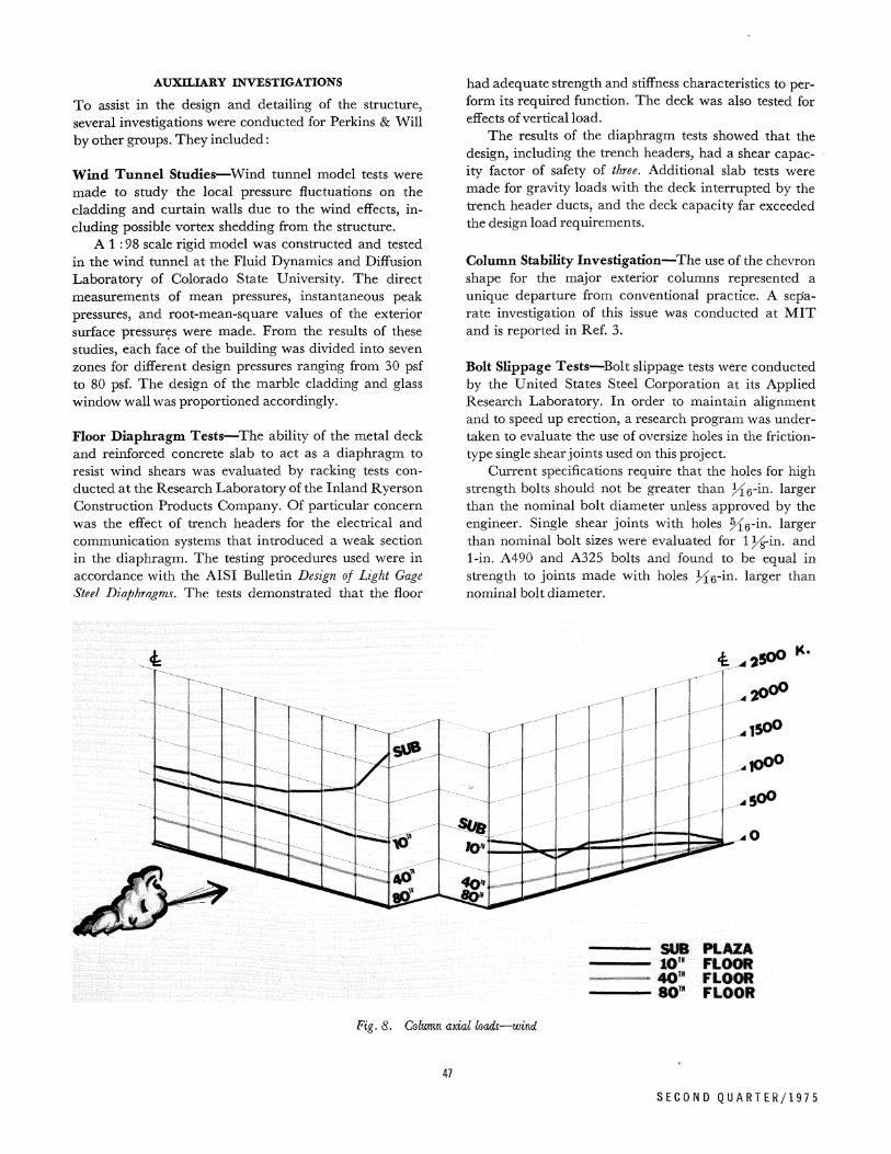
SUB PLAZA 10" FLOOR 40' FLOOR SO"" FLOOR Fig. 8. Cakmn axial kads,—wivd
47
S E C O N D Q U A R T E R / 1 9 7 5
SUB PLAZA to" wmm my wmtm my nmm
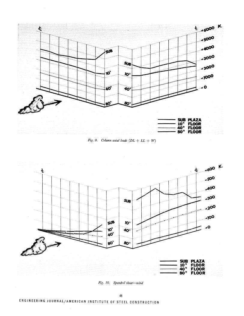
Fig. 9. Column axial loads (DL + LL + W)
K.
SUB PLAZA lO" FLOOR 40" FLOOR 80" FLOOR
Fig. 10. Spandrel shear—wind
48
E N G I N E E R I N G J 0 U R N A L / A M E R I C A N I N S T I T U T E OF STEEL C O N S T R U C T I O f

STRUCTURAL BEHAVIOR
Figures 8 and 9 show curves of column load distributions under wind load and under dead plus live plus wind load, respectively. In Fig. 10 the shears in the spandrel beams under wind loads are plotted, all based on the computer analysis of the building that represented each and every member in one-fourth of the structure, using the symmetry of the building about its two axes.
Note that the desired tube effect has been achieved and actual member load distribution is essentially as expected in a hollow tube very closely complying with the back-of-an-envelope computation of P/A =b MlZ that was made in the preliminary design.
STEEL TONNAGE
One of the main objectives in developing tube behavior of the structure was to minimize the total tonnage of steel used in the structural frame, and this objective was achieved, resulting in 50,506 tons. This weight was distributed as follows:
Floor trusses 4,606 tons Floor beams and built-up
girders Spandrels
Interior columns Exterior columns Re-entrant corners Splices Base Plates
Total
9,878 tons 4,088 tons
18,572 tons
12,226 tons 17,336 tons
1,630 tons 198 tons 544 tons
31,934 tons
50,506 tons
3 6 . 7 %
6 3 . 3 %
Included in this tonnage is approximately 800 tons of 50 ksi yield steel. All other steel is A36.
The resulting steel weight per square foot of floor area was 33 psf. An estimate of the economy of this amount can be seen from Fig. 11, which presents similar data for various high-rise buildings, selected randomly for buildings varying from 20 to 100 stories.
Approximately three-quarters of these were erected after World War I I . All but the John Hancock Center and the Standard Oil of Indiana Building are conventional moment-connected frames, frames with bracing trusses in the cores, or combinations of these systems. Not shown are figures for the Sears Tower in Chicago or the Port of New York Authority Buildings in New York, since to the writer's knowledge the data on these buildings have not been published.
A36 steel was chosen for this job because of its basic economy and ease of welding. Except for the 800 tons of 50 ksi yield steel used in some of the core columns to limit the overall dimension to a 28-in. square using 6-in. plate thickness, all other steel was A3 6. There were no apparent advantages in using higher strength materials.
100
^ 60
•^-STD. jllL OF WO.-clll.
• BEFORE 1945
- AFTER 1945
v4HASf-H.Y.
1401 BROADWAY-.,
IPEHOBSCOTT-DET:
, r-li''IO''8UARDIAII-OET.
EOUITABI]E-CHI>, ' A ' ^ . - fOALLAS BAlK EOUITABLE-ATlr-. \ / • ' . - " i A n O N TOWER^OET. TEMH. BAS - H ( | )ST0 f l -y^^^ , ,JS i - - -ALP0A - PIHS.
CONH. MUT.-CHI; HARRIS TRUST-CHK
GATEWAY-CHI.^:
FT. S H E L F D E T . ^
, tflSHER-OET. ^ * ^ - B O H t O E I \ »̂BECHTEL-S|F. * — P E R BOARD-OET.
INLAUD STEEL - CHI. - H P FED. CHI, FLU. uni^
MOTORS-i)ET.
10 20 30 40 50 60
WEIGHT OF STEEL % . F T .
Fig. n. Comparison of steel weight of various buildings
STEEL ERECTION
The erection of steel started on May 3, 1971 and was scheduled to be completed in 14 months. All steel from the foundation level to the second floor was erected using crawler cranes. From the second floor level to the roof, erection was done using four standard S2 towers supported in the middle of the north, south, east, and west sides of the tower between thq exterior wall and the core (Fig. 12). The stiff^leg derricks on each tower have a capacity of 50 tons at a 30-ft radius and a maximum radius of 120 ft.
The hoist engines were in towers, which were jumped every four floors. Thus the four towers had 20 positions each for a total of 80 positions to complete the work.
The steel erection proceeded rapidly and eflftciently. Figures 13-15 are construction views of the steel erection; Fig. 16 shows the structure just prior to topping out.
49
S E C O N D Q U A R T E R / 1 9 7 5
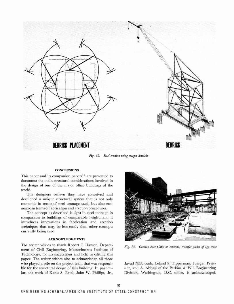
iii(Wim^ noK Fig, 12. Steel erection using creeper derricks
CONCLUSIONS
This paper and its companion papers^-^ are presented to document the main structural considerations involved in the design of one of the major office buildings of the world.
The designers believe they have conceived and developed a unique structural system that is not only economic in terms of steel tonnage used, but also economic in terms of fabrication and erection procedures.
The concept as described is light in steel tonnage in comparison to buildings of comparable height, and it introduces innovations in fabrication and erection techniques that may be less costly than other concepts currently being used.
ACKNOWLEDGMENTS
The writer wishes to thank Robert J. Hansen, Department of Civil Engineering, Massachusetts Institute of Technology, for his suggestions and help in editing this paper. The writer wishes also to acknowledge all those who played a role on the project team that was responsible for the structural design of this building. In particular, the work of Kanu S. Patel, John W. Phillips, Jr.,
Fig. 13. Chevron base plates on concrete; transfer girder of egg crate
Javad Nilforoush, Leland S. Tipperman, Juergen Preis-sler, and A. Abbasi of the Perkins & Will Engineering Division, Washington, D.C. office, is acknowledged.
50
E N G I N E E R I N G J O U R N A L / A M E R I C A N I N S T I T U T E OF STEEL C O N S T R U C T I O N

Fig, 14 Base plates for interior core columns
Fig. 15. Start of steel erection
Also acknowledged are Robert D. Logcher and Robert Wells of Engineering Computer International, Inc., Cambridge, Massachusetts, for consultation on the Computer Analysis; Thomas G. Harmon, other students, and the staff at the Massachusetts Institute of Technology who took par t in a Perkins & Will program, under the direction of Hansen, to experience firsthand the design process and investigate many of the unique problems encountered by the engineers in the design of this structure.
The writer wishes to acknowledge the architectural team of Edward Durell Stone and Associates and The Perkins & Will Corporation, the project designers and architects, for their willingness to understand and
Fig. 16. Construction progress as of September, 1971
explore the unique structural system and to make those compromises generally required of both architect and engineer in development of new ideas.
The work of Turner Construction Company, under the direction of Bernard J. Newton, and American Bridge Division of U.S. Steel Corporation, the structural steel fabricator, merits acknowledgment for the successful construction of this structure.
Finally^ the writer wishes to thank Charles H. Mottier, Jr. of the Standard Oil Company of Indiana for the very active and helpful role he and his staff played throughout the design and construction periods.
REFERENCES
1. Patel, K. S., et al. Computer Aided Design—Standard Oil of Indiana Building Journal of the Structural Division, ASCE, Vol. 99, No. ST4, Proc. Paper 9643, Apr., 1973, pp. 621-635.
2. Picardi, E. A. The Structural Description of the John Hancock Center—Chicago Journal of the Boston Society of Civil Engineers, Vol. 54, No. 1, Jan., 1967, pp. 1-24.
3. Roesset, J. M., et al. Structural Problems—Standard Oil of Indiana Building Journal of the Structural Division, ASCE, Vol. 99, No. ST4, Proc. Paper 9644, Apr. 1973, pp. 637-654.
51
S E C O N D Q U A R T E R / 1 9 7 5