structural technical report 3 - penn state college of
TRANSCRIPT

Structural Technical Report 3 Kelly J. Doyle Structural Option Brunswick School Athletic Building, Greenwich, CT 11/13/2002 Consultant: Dr. Boothby
www.som.com
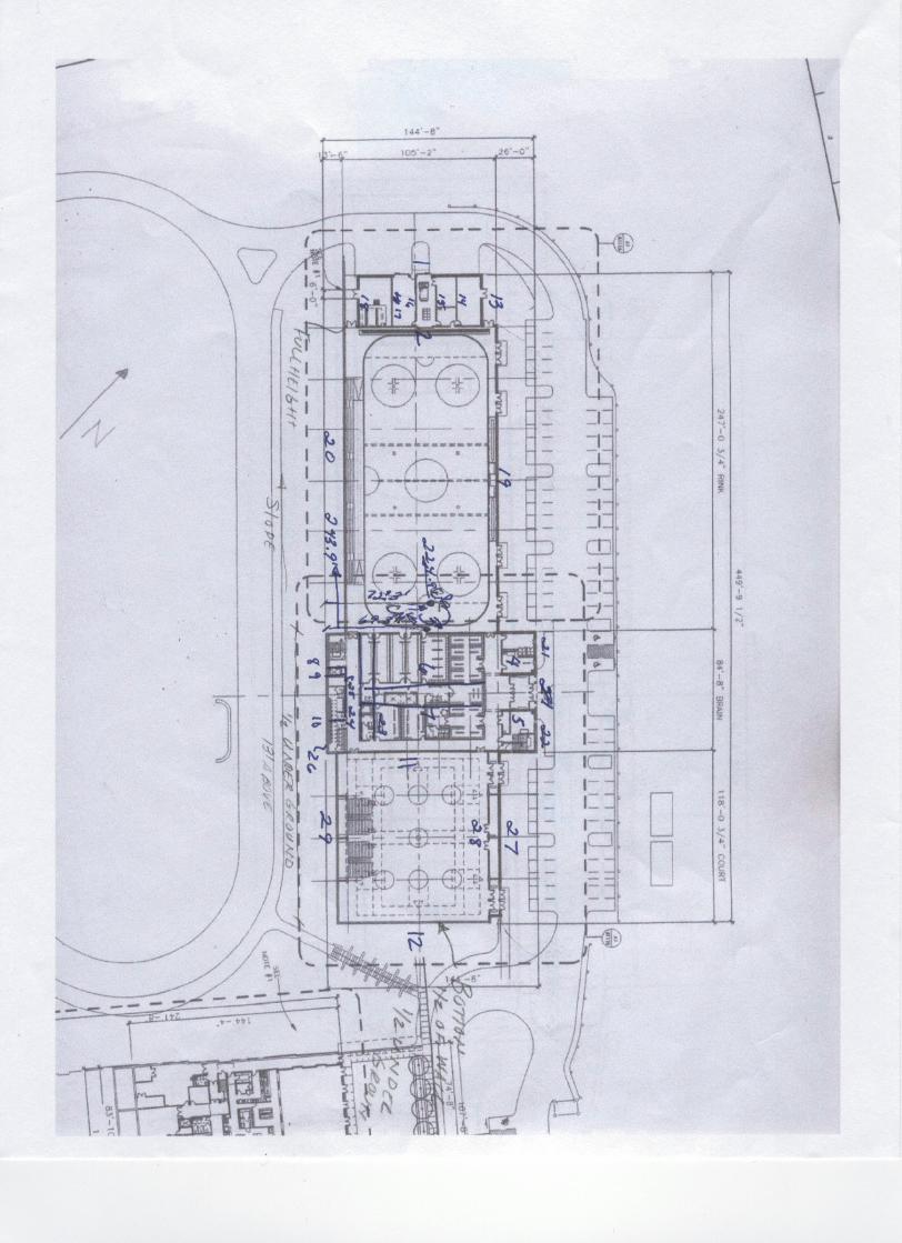
Executive Summary The following report is an analysis and confirmation of the lateral force resisting system in the Brunswick School Athletic Building. This building has a definitive long direction, referred to as X, nearly 450 feet spanning NW-SE and a short direction, called Y, 105 feet spanning NE-SW. Location of the directions, X and Y labeling can be seen on the enclosed first floor plan. Roof trusses span the 105 foot direction, and are spaced 35 feet on center. Load combinations are discussed; seismic loads controlled all of the analysis but roof uplift. This building consists of timber trusses on masonry walls; therefore the analysis includes a complete shear and torsion distribution, a check of roof uplift, and the effects of the lateral forces on the foundation. Shear and torsion distribution was performed over the 29 various shear walls, 12 in the short direction and 17 in the long direction. The included first floor plan shows the numbering these walls. Distribution over these walls was determined using an Excel spreadsheet, and results of wind, seismic, and a combination of wind and seismic loads is included. Shear loadings per each wall were calculated, and compared to the maximum shear resistance in 12”, 10”, and 8” CMU walls. All shear loads were well resisted by the shear reinforcement of 2-#9 bars at 16”. Roof uplift loads are distributed to each truss and compared to the dead load of the roof; uplift was found to be minimal compared to dead load. Overturning moment due to the lateral loads in the X and Y directions were calculated and forces resisting them were compared to the dead load of the foundation. The foundation is more than adequate to resist uplift. Overall, every member checked is sufficient to resist the calculated lateral loads.

Structural Technical Report 3 Kelly J. Doyle Structural Option Brunswick School Athletic Building, Greenwich, CT 11/13/2002 Consultant: Dr. Boothby
www.som.com
Lateral System and Load Path Summary The Brunswick School Athletic Building consists largely of masonry walls and a timber truss roof. This building consists of three sections: a hockey rink, a core or “brain” where locker rooms and weight rooms are located, and a basketball court. The following page shows the location of these three sections. The masonry walls transfer all lateral loads to the foundation. Twenty-nine shear walls are also marked on the following page. Load on the roof is transferred into the walls, and this load, as well as that directly on the exterior walls is distributed to the either the 12 walls resisting load in the long direction, or the 17 walls resisting load in the short direction.

Structural Technical Report 3 Kelly J. Doyle Structural Option Brunswick School Athletic Building, Greenwich, CT 11/13/2002 Consultant: Dr. Boothby
www.som.com
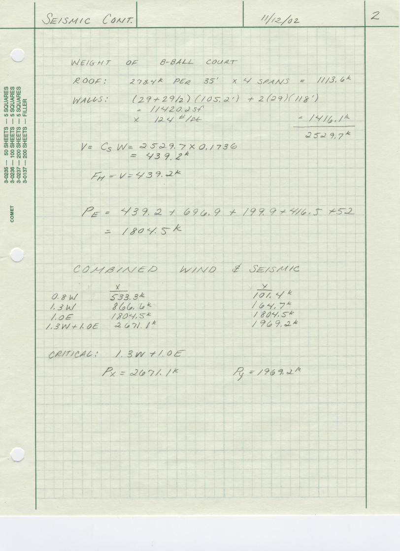
Lateral Load Combinations Wind load on the building is not divided over the sections, but rather over the faces of the building, but seismic is very different. Because the core section has three floors, it has three separate seismic forces. The rink and court are only one story, and therefore only one seismic force each. The following sketches show wind and seismic forces over the building:
Wind loads in pounds per square foot. Summation of the wind forces yielded a force in the long direction Py=127.6 kips, and in the short direction Px=666.6 kips.
Seismic loads by location. Seismic forces not labeled are Fh=696.9 kips and Fb=439.2 kips. Total seismic forces Ps= 1804.5 kips in either direction.
This chart shows the combinations of these loads. The critical combination in each direction is 1.3 W + 1.0 E.
Load Case X Y Unfactored Wind 666.6 k 126.7 k 1.3 W 866.6 k 164.7 k 1.0 E 1804.5 k 1804.5 k 1.3 W + 1.0 E 2671.1 k 1969.2 k

Structural Technical Report 3 Kelly J. Doyle Structural Option Brunswick School Athletic Building, Greenwich, CT 11/13/2002 Consultant: Dr. Boothby
www.som.com
Shear & Torsion Distribution Shear and torsion reactions were distributed over the twenty-nine shear walls using an Excel spreadsheet. The spreadsheet calculated the relative rigidity of each wall and compared it to the total rigidity in each direction. The following chart shows the results in each direction:
Centers of Area and Rigidity are marked on the floor plan. These factors were used to analyze each load case. The loads shown on the
previous page were each entered into the spreadsheet, and direct shear, torsional shear, and the combination of direct and torsional shear were calculated for each wall. The wall with the most shear is Wall 1 (located farthest NE), with V=18.2 kips per foot of wall. Drift due to these forces is also calculated in the spreadsheets. The largest case, combined wind and seismic in the Y direction, shows ∆= 0.00363 inches. Compared to the allowable drift for masonry walls, per IBC 2000, ∆= h/240 = 2.95”, all drift conditions are very small. The spreadsheets for each loading condition are contained on the next three pages.
X Y Total Relative Rigidity 331.3 408.9 Center of Area 224.9 72.3 Center of Rigidity 244.0 69.3 Eccentricity 19.1 3.0

Seismic ShearWall # size
("CMU)thickness (in) depth (ft) height (ft) x (ft) h/d flexibility Rigidity R*x & R*y r r^2 Direct V
(kips)Torsion V
(kips)Total V Shear/length
(k/ft of wall)1 12 11.625 105.2 29 0 0.276 0.026 39.192 0.000 243.989 59530.81 213.492 1539.879 1753.372 16.6672 12 11.625 105.2 29 35 0.276 0.026 39.192 1371.734 208.989 43676.56 213.492 1318.985 1532.478 14.5673 12 11.625 144.67 29 248 0.200 0.018 55.752 13826.603 4.011 16.09 303.700 36.007 267.692 1.8504 8 7.625 25 14 276 0.560 0.096 10.365 2860.868 32.011 1024.68 56.464 53.431 3.032 0.1215 8 7.625 25 14 301 0.560 0.096 10.365 3120.004 57.011 3250.21 56.464 95.161 -38.697 -1.5486 8 7.625 76 14 280.5 0.184 0.025 40.034 11229.635 36.511 1333.03 218.079 235.378 -17.299 -0.2287 8 7.625 76 14 295.5 0.184 0.025 40.034 11830.151 51.511 2653.35 218.079 332.081 -114.002 -1.5008 8 7.625 12 29 270 2.417 2.168 0.461 124.541 26.011 676.55 2.513 1.932 0.581 0.0489 8 7.625 12 29 276 2.417 2.168 0.461 127.309 32.011 1024.68 2.513 2.378 0.135 0.011
10 8 7.625 12 29 308 2.417 2.168 0.461 142.069 64.011 4097.36 2.513 4.755 -2.242 -0.18711 12 11.625 144.67 29 333 0.200 0.018 55.752 18565.560 89.011 7922.89 303.700 799.134 -495.434 -3.42512 12 11.625 105.2 29 449.75 0.276 0.026 39.192 17626.783 205.761 42337.44 213.492 1298.608 -1085.116 -10.315
Vy= 1804.5 kips ∑R = 331.265 ∑V = 1804.5CMx= 449.75/2= 224.875 ft ∑Rx = 80825.258CRx= ∑Rx = 243.989 e= 19.114 ft M= 34491.875 ft-kips M /J= 0.161 kips/ft^2
∑R ∑V/∑R = 5.447 ∆x= 3.03E-03 in
Wall # size ("CMU)
thickness (in) depth (ft) height (ft) x (ft) h/d flexibility Rigidity R*x & R*y r r^2 Direct V (kips)
Torsion V (kips)
Total V Shear/length (k/ft of wall)
13 10 9.625 34 29 118.67 0.853 0.153 6.532 775.180 49.377 2438.11 28.827 51.940 -23.113 -0.68014 10 9.625 34 29 102.67 0.853 0.153 6.532 670.664 33.377 1114.04 28.827 35.110 -6.283 -0.18515 10 9.625 34 29 65.4 0.853 0.153 6.532 427.208 3.893 15.15 28.827 4.095 32.922 0.96816 10 9.625 34 14 53.3 0.412 0.050 19.986 1065.271 15.993 255.77 88.200 51.472 139.672 4.10817 10 9.625 34 29 38 0.853 0.153 6.532 248.225 31.293 979.24 28.827 32.917 61.744 1.81618 10 9.625 34 29 23.5 0.853 0.153 6.532 153.507 45.793 2096.98 28.827 48.170 76.996 2.26519 12 11.625 213 29 128.67 0.136 0.012 83.830 10786.365 59.377 3525.65 369.941 801.552 -431.611 -2.02620 10 9.625 213 29 13.5 0.136 0.014 69.407 936.999 55.793 3112.84 306.295 623.588 929.883 4.36621 12 11.625 28 59 144.67 2.107 0.986 1.014 146.715 75.377 5681.72 4.475 12.310 -7.834 -0.28022 12 11.625 28 59 144.67 2.107 0.986 1.014 146.715 75.377 5681.72 4.475 12.310 -7.834 -0.28023 12 11.625 72 29 32 0.403 0.040 24.833 794.667 37.293 1390.75 109.590 149.133 258.723 3.59324 8 7.625 72 14 22 0.194 0.026 37.786 831.285 47.293 2236.61 166.748 287.764 454.512 6.31325 8 7.625 38 59 13.5 1.553 0.694 1.440 19.439 55.793 3112.84 6.354 12.937 19.291 0.50826 12 11.625 84 59 0 0.702 0.090 11.083 0.000 69.293 4801.49 48.910 123.670 172.580 2.05527 12 11.625 117.75 29 128.67 0.246 0.022 44.502 5726.096 59.377 3525.65 196.388 425.515 -229.127 -1.94628 12 11.625 117.75 29 121 0.246 0.022 44.502 5384.764 51.707 2673.64 196.388 370.550 -174.161 -1.47929 10 9.625 117.75 29 6 0.246 0.027 36.846 221.075 63.293 4005.98 162.601 375.541 538.142 4.570
Vx= 1804.5 kips ∑R = 408.905 ∑V = 1804.5CMy= 144.67/2= 72.335 ft ∑Ry = 28334.174CRy= ∑Ry = 69.293 e= 3.042 ft M= 5489.663 ft-kips M /J= 0.026
∑R ∑V/∑R = 4.413 ∆y= 2.45E-03 inJ= ∑ ri^2 = 214191.819 ft^2E= 1800 ksi

Wind ShearWall # size
("CMU)thickness (in) depth (ft) height (ft) x (ft) h/d flexibility Rigidity R*x & R*y r r^2 Direct V
(kips)Torsion V
(kips)Total V (kips)
Shear/length (k/ft of wall)
1 12 11.625 105.2 29 0 0.276 0.026 39.192 0.000 243.989 59530.81 19.486 140.548 160.033 1.5212 12 11.625 105.2 29 35 0.276 0.026 39.192 1371.734 208.989 43676.56 19.486 120.386 139.872 1.3303 12 11.625 144.67 29 248 0.200 0.018 55.752 13826.603 4.011 16.09 27.719 3.286 24.433 0.1694 8 7.625 25 14 276 0.560 0.096 10.365 2860.868 32.011 1024.68 5.154 4.877 0.277 0.0115 8 7.625 25 14 301 0.560 0.096 10.365 3120.004 57.011 3250.21 5.154 8.686 -3.532 -0.1416 8 7.625 76 14 280.5 0.184 0.025 40.034 11229.635 36.511 1333.03 19.904 21.483 -1.579 -0.0217 8 7.625 76 14 295.5 0.184 0.025 40.034 11830.151 51.511 2653.35 19.904 30.310 -10.405 -0.1378 8 7.625 12 29 270 2.417 2.168 0.461 124.541 26.011 676.55 0.229 0.176 0.053 0.0049 8 7.625 12 29 276 2.417 2.168 0.461 127.309 32.011 1024.68 0.229 0.217 0.012 0.001
10 8 7.625 12 29 308 2.417 2.168 0.461 142.069 64.011 4097.36 0.229 0.434 -0.205 -0.01711 12 11.625 144.67 29 333 0.200 0.018 55.752 18565.560 89.011 7922.89 27.719 72.938 -45.219 -0.31312 12 11.625 105.2 29 449.75 0.276 0.026 39.192 17626.783 205.761 42337.44 19.486 118.526 -99.040 -0.941
Vy= 164.7 kips ∑R = 331.265 ∑V = 164.7CMx= 449.75/2= 224.875 ft ∑Rx = 80825.258CRx= ∑Rx = 243.989 e= 19.114 ft M= 3148.136 ft-kips M /J= 0.015 kips/ft^2
∑R ∑V/∑R = 0.497 ∆x= 2.76E-04 in
Wall # size ("CMU)
thickness (in) depth (ft) height (ft) x (ft) h/d flexibility Rigidity R*x & R*y r r^2 Direct V (kips)
Torsion V (kips)
Total V Shear/length (k/ft of wall)
13 10 9.625 34 29 118.67 0.853 0.153 6.532 775.180 49.377 2438.11 13.844 4.741 9.103 0.26814 10 9.625 34 29 102.67 0.853 0.153 6.532 670.664 33.377 1114.04 13.844 3.205 10.639 0.31315 10 9.625 34 29 65.4 0.853 0.153 6.532 427.208 3.893 15.15 13.844 0.374 14.218 0.41816 10 9.625 34 14 53.3 0.412 0.050 19.986 1065.271 15.993 255.77 42.357 4.698 47.055 1.38417 10 9.625 34 29 38 0.853 0.153 6.532 248.225 31.293 979.24 13.844 3.004 16.848 0.49618 10 9.625 34 29 23.5 0.853 0.153 6.532 153.507 45.793 2096.98 13.844 4.397 18.240 0.53619 12 11.625 213 29 128.67 0.136 0.012 83.830 10786.365 59.377 3525.65 177.662 73.159 104.503 0.49120 10 9.625 213 29 13.5 0.136 0.014 69.407 936.999 55.793 3112.84 147.096 56.916 204.012 0.95821 12 11.625 28 59 144.67 2.107 0.986 1.014 146.715 75.377 5681.72 2.149 1.124 1.026 0.03722 12 11.625 28 59 144.67 2.107 0.986 1.014 146.715 75.377 5681.72 2.149 1.124 1.026 0.03723 12 11.625 72 29 32 0.403 0.040 24.833 794.667 37.293 1390.75 52.630 13.612 66.241 0.92024 8 7.625 72 14 22 0.194 0.026 37.786 831.285 47.293 2236.61 80.080 26.265 106.345 1.47725 8 7.625 38 59 13.5 1.553 0.694 1.440 19.439 55.793 3112.84 3.052 1.181 4.232 0.11126 12 11.625 84 59 0 0.702 0.090 11.083 0.000 69.293 4801.49 23.489 11.288 34.776 0.41427 12 11.625 117.75 29 128.67 0.246 0.022 44.502 5726.096 59.377 3525.65 94.314 38.838 55.477 0.47128 12 11.625 117.75 29 121 0.246 0.022 44.502 5384.764 51.707 2673.64 94.314 33.821 60.494 0.51429 10 9.625 117.75 29 6 0.246 0.027 36.846 221.075 63.293 4005.98 78.088 34.276 112.364 0.954
Vx= 866.6 kips ∑R = 408.905 ∑V = 866.6CMy= 144.67/2= 72.335 ft ∑Ry = 28334.174CRy= ∑Ry = 69.293 e= 3.042 ft M= 2636.377 ft-kips M /J= 0.012
∑R ∑V/∑R = 2.119 ∆y= 1.18E-03 inJ= ∑ ri^2 = 214191.819 ft^2E= 1800 ksi

Combined Wind & Seismic ShearWall # size
("CMU)thickness (in) depth (ft) height (ft) x (ft) h/d flexibility Rigidity R*x & R*y r r^2 Direct V
(kips)Torsion V
(kips)Total V (kips)
Shear/length (k/ft of wall)
1 12 11.625 105.2 29 0 0.276 0.026 39.192 0.000 243.989 59530.81 232.978 1680.427 1913.405 18.1882 12 11.625 105.2 29 35 0.276 0.026 39.192 1371.734 208.989 43676.56 232.978 1439.372 1672.350 15.8973 12 11.625 144.67 29 248 0.200 0.018 55.752 13826.603 4.011 16.09 331.419 39.294 292.125 2.0194 8 7.625 25 14 276 0.560 0.096 10.365 2860.868 32.011 1024.68 61.617 58.308 3.309 0.1325 8 7.625 25 14 301 0.560 0.096 10.365 3120.004 57.011 3250.21 61.617 103.846 -42.229 -1.6896 8 7.625 76 14 280.5 0.184 0.025 40.034 11229.635 36.511 1333.03 237.983 256.862 -18.878 -0.2487 8 7.625 76 14 295.5 0.184 0.025 40.034 11830.151 51.511 2653.35 237.983 362.390 -124.407 -1.6378 8 7.625 12 29 270 2.417 2.168 0.461 124.541 26.011 676.55 2.742 2.108 0.634 0.0539 8 7.625 12 29 276 2.417 2.168 0.461 127.309 32.011 1024.68 2.742 2.595 0.147 0.012
10 8 7.625 12 29 308 2.417 2.168 0.461 142.069 64.011 4097.36 2.742 5.189 -2.447 -0.20411 12 11.625 144.67 29 333 0.200 0.018 55.752 18565.560 89.011 7922.89 331.419 872.072 -540.653 -3.73712 12 11.625 105.2 29 449.75 0.276 0.026 39.192 17626.783 205.761 42337.44 232.978 1417.134 -1184.156 -11.256
Vy= 1969.2 kips ∑R = 331.265 ∑V = 1969.2CMx= 449.75/2= 224.875 ft ∑Rx = 80825.258CRx= ∑Rx = 243.989 e= 19.114 ft M= 37640.012 ft-kips M /J= 0.176 kips/ft^2
∑R ∑V/∑R = 5.944 ∆x= 3.30E-03 in
Wall # size ("CMU)
thickness (in) depth (ft) height (ft) x (ft) h/d flexibility Rigidity R*x & R*y r r^2 Direct V (kips)
Torsion V (kips)
Total V Shear/length (k/ft of wall)
13 10 9.625 34 29 118.67 0.853 0.153 6.532 775.180 49.377 2438.11 42.671 56.681 -14.010 -0.41214 10 9.625 34 29 102.67 0.853 0.153 6.532 670.664 33.377 1114.04 42.671 38.314 4.357 0.12815 10 9.625 34 29 65.4 0.853 0.153 6.532 427.208 3.893 15.15 42.671 4.469 47.139 1.38616 10 9.625 34 14 53.3 0.412 0.050 19.986 1065.271 15.993 255.77 130.557 56.170 186.727 5.49217 10 9.625 34 29 38 0.853 0.153 6.532 248.225 31.293 979.24 42.671 35.921 78.592 2.31218 10 9.625 34 29 23.5 0.853 0.153 6.532 153.507 45.793 2096.98 42.671 52.566 95.237 2.80119 12 11.625 213 29 128.67 0.136 0.012 83.830 10786.365 59.377 3525.65 547.603 874.711 -327.108 -1.53620 10 9.625 213 29 13.5 0.136 0.014 69.407 936.999 55.793 3112.84 453.391 680.504 1133.895 5.32321 12 11.625 28 59 144.67 2.107 0.986 1.014 146.715 75.377 5681.72 6.625 13.433 -6.809 -0.24322 12 11.625 28 59 144.67 2.107 0.986 1.014 146.715 75.377 5681.72 6.625 13.433 -6.809 -0.24323 12 11.625 72 29 32 0.403 0.040 24.833 794.667 37.293 1390.75 162.219 162.745 324.964 4.51324 8 7.625 72 14 22 0.194 0.026 37.786 831.285 47.293 2236.61 246.828 314.028 560.856 7.79025 8 7.625 38 59 13.5 1.553 0.694 1.440 19.439 55.793 3112.84 9.406 14.117 23.523 0.61926 12 11.625 84 59 0 0.702 0.090 11.083 0.000 69.293 4801.49 72.398 134.957 207.356 2.46927 12 11.625 117.75 29 128.67 0.246 0.022 44.502 5726.096 59.377 3525.65 290.703 464.353 -173.650 -1.47528 12 11.625 117.75 29 121 0.246 0.022 44.502 5384.764 51.707 2673.64 290.703 404.370 -113.668 -0.96529 10 9.625 117.75 29 6 0.246 0.027 36.846 221.075 63.293 4005.98 240.689 409.817 650.506 5.524
Vx= 2671.1 kips ∑R = 408.905 ∑V = 2671.1CMy= 144.67/2= 72.335 ft ∑Ry = 28334.174CRy= ∑Ry = 69.293 e= 3.042 ft M= 8126.040 ft-kips M /J= 0.038 C
∑R ∑V/∑R = 6.532 ∆y= 3.63E-03 inJ= ∑ ri^2 = 214191.819 ft^2E= 1800 ksi

Structural Technical Report 3 Kelly J. Doyle Structural Option Brunswick School Athletic Building, Greenwich, CT 11/13/2002 Consultant: Dr. Boothby
www.som.com
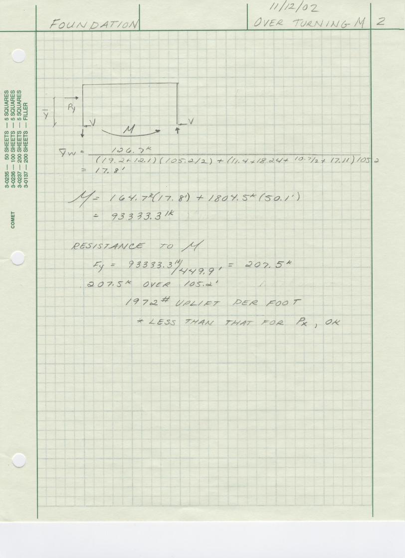
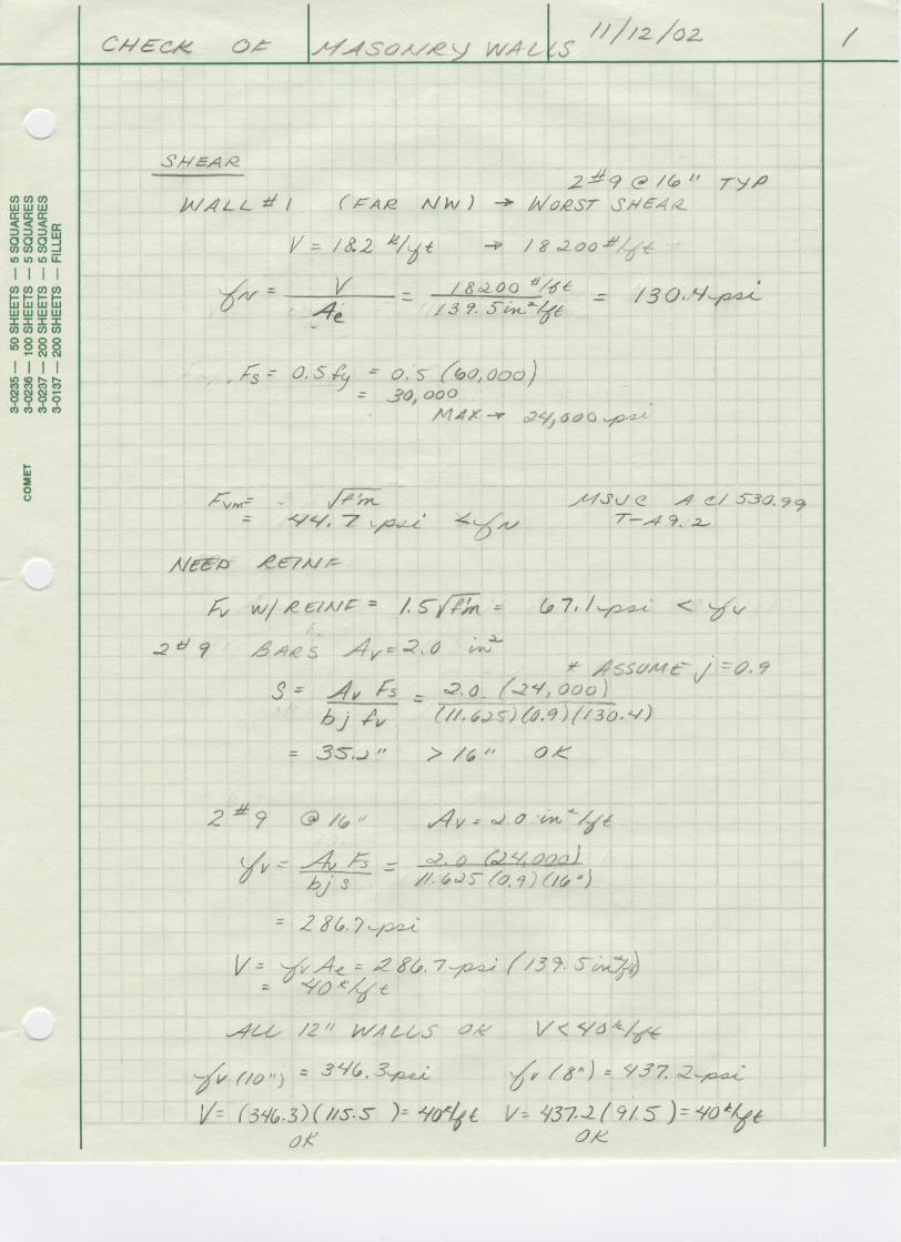
Member Loading Checks The following cases were checked: shear on masonry walls, roof uplift, and load on the foundation. Calculations can be reviewed in the included calculation section of this report. Shear forces from the Excel spreadsheet in the previous section were checked. It was determined that each wall, reinforced with 2-#9 bars @ 16” could resist 40 kips per foot off wall. The worst case, in Wall 1, was 18.2 kips per foot, well below the allowable limit. All shear walls are sufficient to carry the shear load to the foundation. The roof uplift was determined due to upward forces and overturning moment in the roof. The maximum uplift force is 2.5 kips per truss, spaced 35 feet on center. The dead load per 35 foot span of roof is 278.4 kips, much higher than the uplift load. Two cases of overturning moment for the building were analyzed, one in each direction. The moment due to forces in the X direction were 107000 foot-kips, and reactions resisting this moment were 2.26 kips per foot of wall. The dead load per foot in this direction is 329.2 kips, much greater than the uplift on the foundation. Loads in the Y direction induce 93000 foot-kips of moment, or 2.0 kips per foot of wall. Dead load in this direction is 150.6 kips, again much greater than the uplift.

Structural Technical Report 3 Kelly J. Doyle Structural Option Brunswick School Athletic Building, Greenwich, CT 11/13/2002 Consultant: Dr. Boothby
www.som.com
Summary After analysis, it was determined that all of the shear walls in the Brunswick School Athletic Building are sufficient to carry the direct and torsional shear forces imposed by either wind or seismic loads, as well as a combination of these forces. The significant weight of this building caused seismic loads to control loadings. All roof and foundation uplift forces are more than balanced by dead load forces. Wall deflection values are well within the IBC limits. The lateral system for this building is quite sufficient for the loads it will encounter.