structural vibrationprediction - nasa vibrationprediction ... has indicated a need for uniform...
TRANSCRIPT

NASASPACEVEHICLEDESIGNCRITERIA(STRUCTURES)
NASA SP-8050
STRUCTURALVIBRATIONPREDICTION
0 JUNE1970
NATIONAL AERONAUTICS AND SPACE ADMINISTRATION
https://ntrs.nasa.gov/search.jsp?R=19710009806 2018-06-08T06:01:01+00:00Z

FOREWORD
NASA experience has indicated a need for uniform criteria for the design of space
vehicles. Accordingly, criteria are being developed in the following areas of technology:
Environment
Structures
Guidance and Control
Chemical Propulsion
Individual components of this work will be issued as separate monographs as soon as
they are completed. A list of all previously issued monographs in this series can be
found at the end of this document.
These monographs are to be regarded as guides to design and not as NASA
requirements, except as may be specified in formal project specifications. It is
expected, however, that the criteria sections of these documents, revised as experience
may indicate to be desirable, eventually will become uniform design requirements for
NASA space vehicles.
This monograph was prepared under the cognizance of the Langley Research Center.
The Task Manager was G. W. Jones, Jr. The author was J. S. Archer of TRW Systems
Group/TRW Inc. A number of other individuals assisted in developing the material and
reviewing the drafts. In particular, the significant contributions made by R. E. Blake of
Lockheed Missiles & Space Company; R. Chen and D. L. Keeton of McDonnell Douglas
Corporation; S. A. Clevenson of NASA Langley Research Center; H. Himelblau of
North American Rockwell Corporation; W. C. Hurty of the University of California,
Los Angeles; G. Morosow of Martin Marietta Corporation; and A. G. Piersol of
Measurement Analysis Corporation are hereby acknowledged.
June 1970

For sale by the National Technical Information Service, Springfield, Virginia 22151 - Price $3.00
CONTENTS
1. INTRODUCTION ...................... 1
2. STATE OF THE ART .................... 5
2.1
2.2
Analytical Determination of Vibration Response ......... 5
2.1.1 Extrapolation Response Analysis ............ 6
2.1.1.1 Scaling Methods .............. 6
2.1.1.2 Frequency Response Methods ......... 7
2.1.2 Deterministic Response Analysis ............ 8
2.1.2.1 Mathematical Structural Modeling ........ 8
2.1.3
Tests
2.2.1
2.2.2
2.2.3
2.2.4
2.2.5
2.1.2.2 Response Formulation and Solution ....... l0
Statistical-Energy Response Analysis .......... 13
........................ 13
Static Tests ................... 14
Vibration Tests .................. 14
Acoustic Tests .................. 16
Field Tests .................... 16
Flight Tests ................... 17
3. CRITERIA ........................ 17
3.1 Data Required ..................... 18
3.2 Analytical Determination of Vibration Response ......... 18
3.3 Tests ........................ 18
4. RECOMMENDED PRACTICES 18
4.1
4.2
Data Required ..................... 19
Analytical Determination of Vibration Response ......... :20
4.2.1 Extrapolation Response Analysis ............ 20
4.2.2 Deterministic Response Analysis ........... ;20
4.2.3 Statistical-Energy Response Analysis ........... 22
.°.
111
4.3 Tests
4.3.1
4.3.2
4.3.3
4.3.4
4.3.5
........................ 22
Static Tests ................... 24
Vibration Tests .................. 24
Acoustic Tests .................. 25
Field Tests .................... 25
Flight Tests ................... 25
REFERENCES ....................... 27
NASA SPACE VEHICLE DESIGN CRITERIA
MONOGRAPHS ISSUED TO DATE ............... 37
iv

STRUCTURAL VIBRATION PREDICTION
1. INTRODUCTION
A space vehicle is subjected to significant vibratory loads by the natural and induced
environments encountered during its life. To consider properly the effect of vibration
in the design of a space vehicle, it is necessary to predict the structural responses and
internal loads resulting from the vibratory inputs to the structure.
This monograph is concerned with the determination of the space-vehicle structural
vibration resulting from induced or natural environments, and with determining
internal structural loads and stresses caused by such vibrations. The vibration sources
are assumed to be described adequately; the content of the monograph is therefore an
assessment of analytical and experimental methods of determining the resulting
vibrations, and internal loads and stresses, and an enumeration of means of
demonstrating the validity of these data.
Structural vibration is an oscillatory motion of a structural system which can be
characterized by certain parameters that are invariant with respect to time, in contrast
to a transient or shock response. After the initial shock, however, the structural
response to some transients or shock loadings characteristically varies slowly enough
with time so that this portion of the response may be treated as a vibration. Vibration
may be periodic or random (or a combination of both).
Structural vibration causes internal loads and stresses in structural components and
localized loads at attachment points where equipment is supported by the structure.
The degree or magnitude of structural response may be expressed as an acceleration or
displacement of various critical points as a function of time, as a weighted average
acceleration (root mean square), or as spectra of acceleration or stresses as functions of
frequency at discrete times. Severe vibration of space-vehicle structural elements
usually results from rocket noise and from aerodynamic noise and buffet. Severe
vibration can also result from other sources, such as thrust oscillation and
rocket-engine resonances, wind gust and shear, transportation, tests, operation of
internal equipment, and unstable dynamic coupling of the structure with the control
system or with the propulsion system.

TableI lists the operational phases of a space-vehicle mission and the possible sources
of vibration in each phase. Figure 1 illustrates a typical time history of the vibration of
a launch vehicle, measured during the launch operation. It can be seen that structural
vibration is significant during the launch phase of flight, and may also be significant
during prelaunch, space, and entry operations.
TABLE I. - SOURCES OF VIBRATION
IN VARIOUS VEHICLE OPERATIONAL PHASES
Operation Phase Source
Prelaunch Functional checkout
Launch
Space
Atmospheric
Transportation:
Air
Ground
Water
Launch readiness
Liftoff
Ascent
Staging
On station
Entry
Vibration testing
Static firing
Air turbulence
Propeller noise
Rough highways
Rough water
Ground wind
Ignition
Engine noise
Tie-down release
Engine roughness
Aerodynamic noiseand buffet
Pogo phenomena
Control-systeminstability
Separation
Stage ignition
Control-systeminstability
Aerodynamic noiseand buffet
Aerodynamic stability

O 0 0
6 'uoqeJala33e
snoaue]uelsu I
m
I
i !
l ....l
/
i .....
,;f,....2
,-t t--t---÷-t--
: 1
- +-t-- --
S_J_5 'uo!|eJal_o3R SI_I:J
o-,t
7.-I
?
c_
r_
c_
o
.=o
9 o
$
o
o
.o
/ ..... J .... [''' I' ' I " [ ' ] 0
ZHtE8 'Al!suap le_l_acls uo!le_ala33_'
%
=.._............. t,t' F7_i¢I'_.:_ _:. _T
il L i iiiilg// I o
ZH/E6 'A),!suap leJloads uo!le_)la:3oV _.
u'} _ •
0 0 0 0
%
i ...... : ......... I:;[I ] [ _
_ _ o % %
%
%
ZH/E6 'A),!suap leJ]3ads u0!leJela3OV
t--
"t3
ell
e-
--1
g
e-- _
g_
N .__
E "
,_,',_ 0
I
Structural vibration may cause overstressing, fatigue from oscillation of the induced
loads and stresses, malfunction of electrical and mechanical components (such as
switch chatter and valve leakage), and excessive structural deflections which render
equipment inoperative, or the vibration may exceed limits for pilot or crew. Structural
vibration was of concern or actually resulted in failure in the following instances:
Torsion vibration during staging of a major launch vehicle required close
design attention to payload torsion characteristics to minimize loads and
accelerations on the spacecraft structure.
Control-system coupling with a launch-vehicle structure in the launch mode
required engine shutdown to prevent failure from vibration of the structure
while the vehicle was supported oll the launch stand, thus requiring
control-system redesign.
Several launch vehicles experienced pogo-type longitudinal vibration (caused
by unstable coupling of propulsion system with longitudinal structural
vibration) that caused excessive loads and resulted in booster malfunction.
Failure of structure in prototype space-vehicle testing frequently occurred
from overstress caused by inadequate analysis during the development and
qualification phases of tile program.
Consideration of instabilities associated with coupling between structural and control
or propulsion systems is closely related to the vibration response problem. Although
stability considerations of this nature are dealt with in other monographs and regarded
primarily as a control problem or a special structure-propulsion interaction problem
(e.g., pogo), it is important that the structural engineer provide adequate support for
accurate modeling of the structure for use in stability analysis. The structural model
used for response analyses, at least in the lower frequencies, is often the appropriate
model to be used for the stability analysis.
Important considerations in vibration analysis which affect the accurate determination
of the vibratory displacements, loads, and stresses are the adequacy of the description
of the applied loading, the selection and formulation of an adequate mathematical
model, and the accurate assessment of the magnitude of tile damping of the structural
system.
Once the externally applied loading from natural or induced environments which
cause structural vibration has been determined, the basic approach to determination of
the vibrations and the resulting internal loads and stresses is to rely on empirical and
theoretical analysis, verified by vibration tests under simulated environments.
Analytical techniques utilizing linear structural parameters for prediction of structural
vibration in the lower frequency range are well established. However, heavy reliance is
placed upon extrapolation of flight-vibration measurements on earlier vehicles to verify
and supplement deterministic analysis, upon additional vibration data taken during
development and qualification vibration tests, and on supplementary data taken during
static-deflection tests to verify adequacy of the structural analysis.
This monograph is related to other planned or published NASA Design Criteria
monographs which treat the inputs to and the responses of vehicle structure in various
natural and induced environments. These related monographs cover natural vibration
modal analysis, determination of environmental vibration loading, special
vibration-instability problems, and other structural dynamic transients.
2. STATE OF THE ART
In general, space-vehicle structural design is based mainly on the assessment of the
steady-state or quasi-static loads, with some factors added to allow for dynamic loads,
including vibratory response loading. The design is then examined to see if it can
withstand the various dynamic-load effects. The primary problems from vibration are
fatigue and overstressing of the structure and the effects of the amplitude and
frequency of the vibration as an input to equipment or nonstructural systems attached
to the structure.
Analytical techniques for prediction are not highly refined for high-frequency
responses. Thus, experimental techniques are often used to supplement analysis. A
considerable amount of literature is available on both analytical and experimental
techniques, providing a framework within whi6h adequate guides may be obtained for
design purposes.
2.1 Analytical Determination of Vibration Response
Various methods are available for determining the magnitude of structural vibrations
and predicting equipment vibration loads. These methods may be divided into the
following categories:
i. Extrapolation methods
2. Deterministic analysis
3. Statistical-energy analysis
Extrapolation methods use experimental data obtained on one vehicle to predict the
vibration of a new vehicle. In deterministic analysis, the vehicle structure is represented
by a mathematical model; the applied load is characterized in either the time or the
frequency domain and, in addition, particularly for aeroacoustic loading, in the spatial
domain; and the predicted vibration at various locations on the structure is directly
calculated, using classical dynamic response techniques applied to the mathematical
model. Statistical-energy analysis has been developed to estimate the vibration of
complex structures subjected to random loading at the higher resonant frequencies.
2.1.1 Extrapolation Response Analysis
The extrapolation approach is a common technique for predicting vibration levels for a
new vehicle, particularly in preliminary design. Extrapolation methods are customarily
used to predict vibration motion, such as acceleration versus frequency for sinusoidal
excitation or acceleration spectral density versus frequency (refs. 1 and 2)* for
random excitation, rather than vibration stress. Since the assumptions made for the
extrapolation of data from one vehicle to another are only partially valid, errors may
result. Extrapolation methods may be divided into scaling methods and frequency
response methods. A discussion of the merits and limitations of these methods maybe found in references 3 to 5.
2.1.1.1 Scaling Methods
Scaling methods consist of the extrapolation of specific vibration data from a selected
reference vehicle with similar structural and configuration characteristics to predict
vibration levels on a new vehicle. Vibration levels may be predicted for any section of
the structure by extrapolating vibration data measured on that section of the structure
in the reference vehicle. Furthermore, predictions may be obtained for any time of
flight by extrapolating the measurements from tile reference vehicle for flight
conditions that have been identified on the new vehicle (ref. 3).
Three specific scaling methods that have been reported on are the Condos and Butler
Method (ref. 6), tile Barrett Method (ref. 7), and tile Winter Method No. 2 (ref. 3).
Reference 6 describes the scaling of Titan I data to predict vibration levels caused by
acoustic and aerodynamic noise on the structurally similar Titan II. Reference 7
similarly describes the scaling of Saturn I vibralion measurements to predict
acoustically induced vibrdtion levels on uprated Saturn l and Saturn V vehicles.
*These references define acceleration spectral density as the mean squared acceleration per unit bandwidth.
6
Reference7 describesa scalingmethodfor mechanicallytransmittedvibration fromliquid-fueledrocket enginesthrough a structurewhich is not primarily excited by
acoustic or aerodynamic noise. For example, engine components and structure near
engines which do not have large exposed surface areas are excited primarily by
mechanically transmitted vibration. The Winter Method No. 2 (reL 3) is similar to the
frequency response methods.
The major advantage of these scaling methods is that the vibratory motion of a new
vehicle can be readily estimated by the designer even without his having knowledge of
the detailed characteristics of its structure. This is highly desirable during early
development of a vehicle, when the structure is incompletely defined and detailed
calculations arc not possible. The procedure can be applied to any type of structure in
any flight vehicle for any llight condition, provided appropriate measurements are
available from the reference vehicle. However, accuracy of the predictions is heavily
dependent upon the quantity and quality of the measurements from the reference
vehicle and upon the similarity of the reference vehicle to the new vehicle.
In addition to these techniques, the theory of mechanical impedance has recently been
applied to the scaling of interface vibration environments based on measured flight
data (rcfs. 8 and 9). This approach exploits the advantages of including the effects of
the dynamic characteristics of the booster and payload in defining the vibration
environment. If the payload and booster mechanical impedance are defined and the
response at the interface is known, then by classical impedance methods the interface
response with a new payload can be determined. Results obtained by this method have
shown promise toward increasing accuracy of interface-vibration-level definition. The
major difficulties encountered in the application of this concept are the lack of
adequate flight data and the difficulty in generating an adequate definition of the
mechanical impedance. The latter problem often requires the combined use of
analytical and experimental results.
2.1.1.2 Frequency Response Methods
Frequency response methods extrapolate from pooled general vibration data measured
on one or more general vehicles to predict vibration levels on a new vehicle. This
approach includes procedures using empirical relationships developed from regression
studies of past data to predict vibration levels in future vehicles. Seven specific
procedures which have been reported on (ref. 3) are the Mahaffey and Smith Method
(ref. 10); the Brust-tlimelblau Method (ref. 11); the Eldred, Roberts, and White
Method No. 1 (ref. 12); the Eldred, Roberts, and White Method No. 2 (ref. 12); the
Curtis .Method (ref. 13); the Franken Method (ref. 14); and the Winter Method No, 1
(ref. 3).
7
Frequency response methods determine the ratio of vibration to the magnitude of the
fundamental source as a function of frequency or bandwidth. The fundamental source
is generally acoustic or aerodynamic noise applied to the vehicle surface. Reference 10
describes the first use of this method, which was based on data obtained on the B-52
and B-58 aircraft; reference 11 extends the reference 10 approach to provide average
acceleration spectral density rather than peak acceleration. Reference 12 describes use
of tile technique based on vibration and acoustic measurements obtained on the Snark
missile; reference 13 correlates vibration measurements on high-speed aircraft to the
aerodynamic pressure. Reference 14 describes a similar vibration and acoustic
measurement study of Jupiter and Titan I external structure behavior during
rocket-engine static firing; Winter has modified the results of reference 14 after adding
Minuteman, Skybolt, and Genie data.
Frequency response methods are used to calculate the vibration response of a new
vehicle without considering the detailed characteristics of its structure. In some cases,
the overall accuracy is good, while in other cases considerable overprediction and
underprediction have resulted (e.g., refs. 3, 6, and 11). Although these methods are not
generally used for determining vibration stresses, they can be modified (refs. 15 to 17)
to establish acceleration-versus-stress relationships which in turn can be used for
extending frequency response methods. Stress extrapolation comparisons have been
poor, however, even when acceleration extrapolation comparisons are good (ref. 14).
2.1.2 Deterministic Response Analysis
Deterministic analyses are most useful in predicting vibration stresses and motions in
the lower frequency range. Methods used for these analyses are generally well known
(refs. 2, 5, and 18 to 26). Typically, a rigorous analysis is restricted to that frequency
range which encompasses the lower 10 to 50 modes of the structure. The lack of
structural detail in the model or simplification of the loading description often reduces
further the useful frequency range.
Deterministic analyses require modeling of the environmental source, as well as of the
structure to be analyzed. These sources are discussed in other NASA Design Criteria
monographs.
2.1.2.1 Mathematical Structural Modeling
Selection of the mathematical model for a vibration analysis is influenced by the
desired accuracy and frequency range, the nature of the loading, the details to be
employed in describing the loading, and the cost of computation and model
formulation. The mathematicalmodel is a prime factor in obtainingsatisfactoryvibration responseanalyses.Thestructuralstiffnessdistribution,massdistribution,andboundary conditions are eachgivencareful considerationin the synthesisof themathematicalmodel.
Generally,the two typesof modelsavailablearecontinuous-parameterrepresentationsand lumped-parameterrepresentations.Uniformly distributedcontinuous-parameterrepresentationsareusedfor fairly simplestructuresfor whichclassicalsolutionsareknown,e.g.,domes,conicalandcylindricalshells,andplatesandbeams,all with simpleboundaryconditions(refs. 27 to 29). In addition,parametricstudiesfrequentlyusethis approach(ref. 30). Typical complexspace-vehiclestructures,however,usuallyconsistof differenttypesof substructure,whichmakesadistributed-parameteranalysisdifficult andoften impossibleto formulate.Thus,a lumped-parameterrepresentationisusuallypreferredfor modelingthestructure.
The mathematicalmodelingof a structurefor a deterministicvibrationanalysisisessentiallyidenticalto thatrequiredfor naturalvibrationmodalanalysiscoveredin theNASA monographon that subject(ref. 25).Theremainderof this section,presentedfor completeness,is largelyanexcerptfrom Section2.1.1of reference25.
Lumped- or discrete-parameter models of structure are generally fornmlated by a
finite-element approach using matrix notation. These models are synthesized from
independently modeled structural components (finite elements) joined at node points
through common displacement and force coordinates. Finite-element models are
available for beams (ref. 31), flat-plate elements (refs. 32 to 37), shell elements (refs.
38 to 40), and sandwich-plate elements ('ref. 37). The model elements are used in
conjunction with displacement and force coordinates that prescribe the interfacing
geometry of the structural system. The finite-element model leads to the definition of
a stiffness or flexibility matrix and a mass matrix for the discretized system (ref. 20).
Several methods are used to define the mass distribution. These include the
lumped-mass method, the consistent-mass method, and a number of approaches that
use various velocity-interpolation functions to define a mass matrix (ref. 22). The
lumped-mass method distributes the element masses in concentrations located at the
coordinate points in a manner that maintains the center of mass in the structure (refs.
22 and 41 to 43). This method of distribution is well suited for analysis of structures
with preponderantly concentrated masses. Local rotary masses are frequently used
with this method to represent the effect of significant transverse-mass distributions.
The disadvantage of the lumped-mass method is the relatively large number of
coordinate points required for accurate analysis of systems with primarily distributed
masses.
The consistent-mass method represents the mass as it is actually distributed in the
structure (refs. 31, 32, 38, 39, 44, and 45). Although only recently codified, this
method is being widely adopted and incorporated ill modern analytical computer
programs. Tile consistent-mass-distribution method has been shown to yield more
accurate results than the concentrated-mass technique for systems where the mass is
largely distributed in the structure (refs. 41 and 44). A minor disadvantage is that the
nondiagonal mass matrix tends to increase the complexity of the analysis.
The treatment of nonstructural mass, such as liquids in a fuel tank, requires special
consideration. Mechanical coupling of the liquid mass with the structure is generally
accomplished through an equivalent pendulum or spring-mass analogy that simulates
the free-surface lateral-sloshing effect, as described in reference 46. Longitudinal
mechanical coupling may be accomplished through an equivalent spring for the tank's
end bulkhead that supports the liquid (ref. 47). Such analogies permit the solution of
vibratory response problems in a direct fashion without recourse to treatments in fluid
mechanics. A more complex liquid-structure coupling may be treated efficiently with
finite-element models that satisfy the hydroelastic boundary conditions at a number of
points along the liquid boundary. Several such techniques have been developed and
applied (refs. 39 and 48 to 5 i ).
Substructure methods (refs. 52 and 53) may be used in modeling large, complex
structural configurations. These methods offer several advanlages, particularly in such
structures as large multistage vehicle systems where the several stages may be
structurally dissimilar. Substructure methods can be used to extract a larger number of
realistic and accurate high-frequency modes than can be obtained by using a single
model of the entire structure having the same number of degrees of freedom.
The finite-element technique is the most generally applicable of the available analytical
methods. This technique, which is readily adapted to digital-computer solution, takes
maximum advantage of matrix notation in mathematical manipulations. The technique
is being rapidly improved and has been adopted in all major computer programs for
general structural analysis. Vibration response analyses can be performed for almost
any configuration using the finite-element technique. The primary disadvantage of the
finite-element technique is that, owing to the large-sized matrices involved, complex
models use large amounts of computer time.
2.1.2.2 Response Formulation and Solution
Most real structures vibrate nonlinearly; hence, the ratio of the displacement and
stresses to the vibration input is a function of loading magnitude. Unfortunately, there
have been few nonlinear-vibration analyses of mathematical models which approach
10

the complexity characteristic of nearly all space-vehicle structures (ref. 23). When
sufficiently severe nonlinear behavior is expected, it is common practice to assume a
linear model and perform the analysis using linear values of structural stiffness and
damping which represent the expected effect of the nonlinearity on the response.
Otherwise, using results of nonlinear-vibration studies performed on simple models,
such as those reviewed ill reference 23, the linear response is scaled to provide an
approximate or conservative estimate of the nonlinear response.
Mathematical formulation of the linear-vibration response problem generally leads to a
set of second-order, linear, simultaneous differential equations, in terms of
structural-coordinate displacements and forces. These are known as equations of
motion. When arranged using matrix notation, the elastic characteristics of the system
are defined by the displacement-vector coefficient, i.e., the stiffness matrix; the
damping characteristics of the system are defined by the velocity-vector coefficient,
i.e., the damping matrix; and the mass inertial characteristics of the system are defined
by the acceleration-vector coefficient, i.e., the mass matrix. When properly formulated,
the equations of motion yield the natural vibration mode shapes and frequencies or the
structural responses to the inputs. The structural responses may be described as
accelerations and displacements, or as internal loads (the force responses within the
structure) and stresses.
The response solution is frequently obtained by uncoupling the equations of motion
by use of a transformation of coordinates in which the transformation is derived from
the natural modes of the undamped structure (ref. 20). Uncoupled equations may be
solved by several techniques, some of which are the mode-displacement method, the
mode-acceleration method, and the mechanical-admittance or-impedance methods
(refs. 5 and 22). The mechanical-admittance or -impedance methods may be used either
with uncoupled equations or with the coupled system. The choice of the method of
solution is based primarily on the physical nature of the forcing functions. When the
environment can be described in terms of discrete analytical functions in time,
displacement, or velocity, the mode-displacement method has its advantages, since
response for each mode is readily computed and the total response is obtained by
superposition of all modes.
Solution of the homogeneous form of the equations of motion without damping
provides the resonant frequencies and mode shapes which characterize the
mathematical model, and thus, the structure (ref. 25). The modal data are used
principally to determine the vibration response. The resonant frequencies and mode
shapes are also useful in selecting mounting locations for equipment and control
sensors. This is important when known critical frequencies will have detrimental effects
on the equipment or structure. The response of a structure at various frequencies, or at
desired intervals throughout the frequency range of interest, is usually calculated by
11
summingthe responsein each of the orthogonalmodeswhich characterizethestructuralvibration.
Whentheappliedloadingis randomin nature,theresponseisalsorandom.In thiscase,the solution for the vibration responseat a particularlocationon the structureisexpressedasa function of frequencyandreferredto asspectraldensity.References1,2, 20, and 23 provide equationsfor obtaining the displacementspectral-densityresponsedueto spatiallydistributedappliedrandomloading.References2, 23,26,and54 describeseveraldistributionsof cross-correlationfunctionsthat mightbeusedindefining the random characteristicsof various aeroacoustic-noiseloadings.Theaccelerationspectral density, usually preferred in specifying design and testrequirementsfor equipment,is readily obtained from the displacementspectraldensity. Internal loads from which the stressesthroughout the structurecan becalculatedare readilydeterminedfrom root-mean-squaredisplacementderivations.Responsedata relatedto fatigueanalyses,suchasthe numberof responsecyclesandtheprobabilityof peaklevels,mayalsobepredicted(refs. 1and23).
A majorproblemconfrontingtheanalystin predictinganaccuratevibrationresponseishow to determinethe properamountandtype of dampingwhichcharacterizesthevariousvibratingmodes.Viscousdampingisoftenassumedin theequationsof motionbecauseit iscompatiblewith theassumptionof linearvibrationandis thereforeeasytosolvefor dynamicresponse.The dampingof realaerospacestructuresis not viscous,but usually occursas a combinationof materialdamping,friction damping,andacousticradiation(i.e., air damping).An apparentdampingeffectmayalsobepresentbecauseof nonlinearstructuralstiffness,althoughno actualenergydissipationoccurs.
It has been shown experimentallythat materialdampingdependson the stressdistribution(refs. 55and56): if the maximumstressexceedstheendurancelimit, thedampingmayincreasesignificantlyfor mostmaterials.
Friction dampingis the result of energydissipationcausedby slippingor slidingbetweenmatedsurfaces.For aerospacestructuresmadeof partswhichareboltedorriveted together,friction is the dominantsourceof damping.The friction force isapproximatelyconstantandcontrolledby theforcenormalto thematedsurfaces(refs.55, 57,and58). It is difficult to estimatefriction dampingandits distributionin thevariousmodesbecauseof its nonlinearity,thedistributionof thenormalpressureoverthe matedsurfacesbetweenthe fasteners,thevariationsin theforceexertedby eachfastenerthat result from manufacturing,and the spatialvariationsin the staticandkineticcoefficientsof friction.
Another form of damping, acoustic radiation, occurs when acoustic waves,generatedby the vibrationof the structure,arepropagatedto otherstructuresandto
12

surroundingspace.Radiation dampingcan be appreciablefor panelsand otherstructureswith low surfacedensities,unlessthe structurevibratesat high altitude(wherethe radiationis reduced)or unlessthe surroundingspaceisreverberant.Forsimplecases,suchasacousticradiationfrom a rectangularpanelinto a freefield or areverberantspacewith knownsurfacecharacteristics,radiationdampingin thevariousmodescanbeestimated(refs.59 to 64). For morecomplexcases,theestimatingcanbequite involved.Otherformsof dampingmayincludesurfaceandboundarydampingandair pumping(refs.65and66).It isdifficult to estimateproperlythedampingin thevariousmodes,evenfor thesimpleststructuralconfigurations.Thus,to predictdamping,heavyrelianceis usuallyplacedon data from previoustestson similarstructures.
2.1.3 Statistical-Energy Response Analysis
Deterministic methods are frequently ineffective in providing vibration data in the
high-order modes of a structural system. Statistical-energy analysis (refs. 67 to 72) is an
alternate approach for estimating the vibration response of complex structures
subjected to random loading at the higher resonance frequencies. This approach
permits the use of gross structural properties and employs a statistical description of a
structure as a vibrating system; i.e., motion of the system is assumed to be dominated
by resonant response rather than by forced nonresonant response. The response is
predicted on the basis of the average vibration energy contained within a band of
frequencies. The approach is relatively new and has not been widely used as a practical
tool for space-vehicle-vibration predictions.
Statistical-energy analysis techniques have been applied to large, complex vehicle
configurations. Sections of the Saturn V launch vehicle were analyzed to predict
vibration for acoustic noise at liftoff, subsonic and supersonic boundary-layer
turbulence, and shock-induced separation and disturbed flow at various times during
the ascent phase of the mission. The vibration and strain were calculated for each
loading condition (ref. 72). Acoustical and mechanical vibration were investigated by
this technique for a simplified physical model of the OGO spacecraft (refs. 69 and 73).
Although still in an early developmental phase, statistical-energy analysis may be a
valuable tool for interpretation and rough estimates of vehicle vibration above the
lower resonant frequencies.
2.2 Tests
Various experimental tests are used to predict structural vibration response or to refine
earlier predictions during various phases of vehicle development. Tests may be
conducted in tile laboratory, in tile field, or in flight. Laboratory tests may be static
tests, vibration tests, or acoustic tests.
13
2.2.1 Static Tests
Static load-displacement tests are basic to the design-development phase of a
space-vehicle structure and perform an important function in supporting vibration
analyses. These tests may provide some of the data needed to generate the
mathematical model defining the elastic characteristics of the structure, as well as to
verify the mathematical model used in the deterministic analysis. Frequently, static
tests are performed to determine the influence coefficients that define boundary
conditions at an interstage connection with a supporting stage structure. These data are
then used to develop the analytical model. For some large full-scale structures, these
experimental data are approximated by use of detailed subscale models, also known as
replica models (ref. 74). In some cases, the required load-displacement data are
obtained during proof testing of the prototype vehicle.
2.2.2 Vibration Tests
Various laboratory vibration tests are performed to determine the vibration response.
Often these tests are made in conjunction with other tests and analyses. Laboratory
vibration tests include design-development, qualification, and acceptance tests.
Design-development vibration tests are performed to provide information on the modal
characteristics of the structure (ref. 25), to determine the magnitude of the vibration
response, to evaluate the adequacy of the design, and to identify the vibration failure
mechanisms. These vibration tests may consist of sine-sweep, random, or modal tests.
The test-to-failure test is often used during design development to establish margins for
flight and qualification test conditions. These tests are designed and instrumented to
provide vibration response data for specific dynamic-forcing functions.
Qualification vibration tests are performed on flight-quality hardware to demonstrate
the adequacy of the design and fabrication methods for flight. Instrumentation of
these tests is primarily for diagnostic purposes, but it is also useful in providing
vibration response data.
Acceptance vibration tests are performed on articles intended for use in flight to
demonstrate that adequate workmanship has been achieved during fabrication and
assembly. These tests are normally not instrumented and provide no significant
vibration response data.
Other tests include reliability tests (to demonstrate the variation of the failure
mechanism between items of hardware under prescribed types of loading); fragility
tests (to map the failure-threshold perimeter under a variety of loadings or
frequencies); and interim tests between development and qualification.
14

Vibration testsaregenerallyperformedonequipment,onspacecraftstructures,andonmajor launch-vehiclestructures. For example, reference 75 describes the
electrodynamic-shaker excitation of the Ranger spacecraft to envelop the vibration
applied by tile launch vehicle; reference 76 describes a similar test on tile Gemini
spacecraft; reference 77 describes excitation of tile Surveyor spacecraft simulating
vibration during the lunar-descent phase of the mission; reference 78 describes the
vibration tests of several Saturn V sections.
A wide variety of test equipment is available for performing laboratory vibration tests.
Electrodynamic shakers are the most popular because they are easiest to control (in
contrast to hydraulic shakers) with regard to frequency, force output, acceleration
output, and waveform. They are used mostly in the 5- to 2000-Hz frequency range,
although the useful upper-frequency limit usually depends upon the shaker's force
capacity and size. Electrodynamic shakers with force-generating capacities up to
30 000 lb (133 kN) are commerically available. New-generation electrodynamic
systems provide solid-state amplifiers with direct coupling to tile shaker armature, and
can permit operation, within shaker-stroke constraints, down to 0 Hz. Improvements in
shaker construction to give relatively large strokes permit the use of such overall
systems, including multishaker applications, for testing of transients (ref. 79).
Many investigators favor hydraulic shakers principally because of their relatively large
stroke and because of the very-low-frequency performance which is better than can be
obtained with electrodynamic-shaker systems having transformer coupling between
amplifiers and shakers. Hydraulic shakers are used primarily in the 0- to 500-Hz
frequency range, although the useful upper-frequency limit depends on the design
features of the shakers, which vary widely, as well as on their force capacity and size.
Hydraulic shakers with force-generating capacities up to 250 000 lb (1.1 MN) are
commercially available.
In vibration tests, the shaker applies the vibration force in only one direction; the flight
excitation is applied in all directions simultaneously. Usually the assumption is made
that vibration applied sequentially in each of three orthogonal directions for a specified
duration per direction has the same response magnitude as vibration applied in all three
directions simultaneously for the same duration. This assumption is usually valid
only for resonant behavior in one direction; it is valid only by coincidence .whenmultidirectional resonances are excited.
Vibration test inputs may vary. Some tests use sine-sweep inputs, some random inputs,
and others a combination of both. Random inputs are generally representative of
stationary random environments only because of vibration-system-control limitations.
Test levels usually envelop the expected environments for the various prelaunch and
mission events which exhibit high vibration. Often, the time duration selected for the
15
vibration test is the sum of the effective durations of these prelaunch and mission
events.
2.2.3 Acoustic Tests
Since two of the major causes of structural vibration are acoustic noise at liftoff and
aerodynamic noise during the transonic and maxinmm dynamic-pressure regimes, it is
natural to consider acoustic noise as a laboratory source of space-vehicle vibration. The
Titan program first utilized acoustic testing for the development of vehicle structure
subjected to acoustic noise (ref. 80). Acoustic testing was used on the Apollo program
for qualification of equipment, for qualification of structure, and for revision of
vibration design and test requirements (refs. 81 to 84).
Many different (some odd) facilities have been used for acoustic tests. For example,
the Mercury (ref. 85) and OGO spacecraft were tested on the flatbeds of trucks located
in an open field near the discharge nozzle of a large blowdown wind tunnel (ref. 85). A
similar arrangement may be used with a rocket engine as the noise source. Large sections
of the Saturn V launch vehicle were tested in a large reverberant test facility (ref. 86).
The facility used for the acoustic tests of the Apollo lunar module and the command
and service modules is described in references 82, 87, and 88.
Air modulators, such as those used in the Saturn and Apollo acoustic tests, work on
the principle of exhausting high-pressure air through an orifice whose cross-sectional
area is modulated by an electromagnet controlled from an external electrical signal,
usually a random-noise generator. Air modulators generally have limited spectrum
range and control (usually from 50 Hz to 1 kHz), with a spectral maximum in the
vicinity of 100 Hz. Noise generation above 1 kHz is usually determined by the
"unmodulated" flow noise of the air through the orifice. Air modulators are
commercially available in acoustic power capacities up to 200 kW.
Acoustic testing has several advantages over vibration-shaker testing. In acoustic
testing, a large prototype specimen can be tested; thus, the modal characteristics of the
test specimen are similar to those of the flight configuration. The load is distributed
over the external surface, rather than applied as point loading at one or more structural
interfaces. Finally, a reasonable spectrum is often obtained during the acoustic test,
compared with the difficulty of providing a test spectrum by means of a vibration
shaker. The major disadvantage of acoustic testing is the high initial cost of the
facilities to perform these tests properly (ref. 5).
2.2.4 Field Tests
Various field tests, such as rocket-engine and stage- or payload-static firings, are run to
16

demonstratetheoperationalperformanceof variousspace-vehiclesubsystemsprior toflight. These tests are frequently used to provide data for predicting structuralvibrationor revisinganalyticallydetermineddata.
Solid-andliquid-propelledrocketenginesareusuallydesignedandtestedquiteearlyina vehicle'sdevelopmentprogram,sometimesevenbeforethe prime contractorsareselected.Becauseof this early scheduling,testscanbe invaluablein providingtheacoustic-andengine-vibrationdata that areusedfor initial vibrationpredictions.Dataobtainedfrom thesetestsareespeciallyimportantwhena rocketengineincorporatesnewdesignfeatureswhichcanaffectacousticnoiseandvibrationgeneration,but havenot been previously tested or instrumented.However, in making use of therocket-engineacoustic-noisedata, the designermust take into considerationanydifferencesin the test-standandlaunch-padconfigurationsthat mayaffect thenoisegenerationor transmission,suchastheflamedeflector.Also,manyof thecomponentsattachedto the engineduring the early firings are usually not of flight-weightconfiguration,andmayinvalidatethevibrationdata.
2.2.5 Flight Tests
The flight test is almost always used as the final demonstration of the adequacy of the
vibration-load analysis for both vehicles and stages. Nevertheless, in many cases, there
is insufficient instrumentation because, in planning, too little weight and too few
telemetry channels are allocated for instrumentation.
A large number of vibration and acoustic measurements are usually needed during
flight test to demonstrate the adequacy of the vibration and acoustic analysis, to help
in determining the probable cause of a flight failure, and to provide additional data for
the design of future space vehicles. The measurement requirements usually far exceed
the capacity of the telemetry subsystem. Most vibration and aeroacoustic measurements
require a wide bandwidth (ref. 89). Techniques occasionally employed to reduce the
demand on the telemetry subsystem include onboard frequency analysis, onboard tape
recording, and time-division multiplexing.
3. CRITERIA
In the design of a space vehicle, account shall be taken of the effects of the structural
vibration resulting from the environments to which the vehicle may be subjected. The
vibration data needed for structural design shall be determined and verified by a
suitable combination of analysis and tests.
17
3.1 Data Required
The input sources of vibration and the type, amount, and accuracy of the structural
vibration data needed for design shall be defined.
3.2 Analytical Determination of Vibration Response
When measured vibration data are available from a similar vehicle or for a similar
structure and similar environments, a suitable extrapolation method of analysis shall be
used to predict the structural vibration for preliminary design requirements.
A deterministic analysis shall be made to obtain the vibration data needed for design,
except for minor redesign where it can be demonstrated that the results of the
extrapolation analysis are acceptable. The deterministic analysis shall use a
mathenlatical model which adequately represents tile mass distribution, stiffness
distribution, damping, and boundary conditions of the flight vehicle. It shall be
demonstrated, by tests if necessary, that vibration data from the deterministic analysis
are of the type, amount, and accuracy required for structural design.
3.3 Tests
The significant characteristics of load displacement, vibration, and damping of the
space-vehicle structure, if not otherwise adequately established, shall be determined or
verified by a combination of static, vibration, and aeroacoustic testing, as applicable,
on a realistic structure or on an actual vehicle. If full-scale tests are not feasible,
replica-model dynamic tests (for lower order modes) shall be performed.
4. RECOMMENDED PRACTICES
The total plan for investigation of structural vibration resulting from anticipated
environmental sources should be defined and initiated early in the space-vehicle
development program. Vibration and acoustic development tests to confirm the
calculated response and to demonstrate structural adequacy should be planned as an
integral part of the total plan for the structural vibration analysis.
The following steps should be taken in the investigation of structural vibration:
l, Determine the input sources and the type, amount, and accuracy of the
structural vibration data required for structural design of the vehicle.
18
.
,
.
Collect and extrapolate measured input and response data on similar
vehicles.
Construct a mathematical model (or models) adequate for the vibration
analyses, and select or devise a computational method.
Analyze the response of the model to the anticipated vibration
environments.
Conduct vibration and static tests on segments of the structure or on the
complete structure to confirm the calculated response.
4.1 Data Required
All sources of disturbance for all phases of vehicle operation should be considered
during the determination of data required for structural vibration analysis. Vibration
data available from ground and flight tests on similar vehicles should be examined.
Inputs for the vibration analysis should include at least the following:
• Vibration testing during prelaunch functional checkout
• Static firing during prelaunch functional checkout
• Winds during launch readiness
• Ignition and engine noise during launch liftoff
• Engine roughness during launch ascent
• Aerodynamic noise and buffet during launch ascent
• Engine cutoff and stage ignition during launch staging
• Aerodynamic noise and buffet during atmospheric entry
Reference should be made to other NASA Design Criteria monographs for guidance in
obtaining these inputs to the vibration analysis.
No single type of analytical model or degree of model complexity can be
recommended to analyze all configurations of a space vehicle. Since the accuracy of
19
the response analysis varies widely with the complexity of the structure and the order
of the responding modes, the following accuracy numbers should be regarded as guides
only, and should not be taken as requirements without a study to determine their
suitability for the individual problem. In general, calculation of maximum internal
loads in the low-order modes should be accurate to about -+25 percent. Calculation of
maximum internal loads at high-order modes, with respect to attached equipment,
should be accurate to about -+50 percent.
4.2 Analytical Determination of Vibration Response
4.2.1 Extrapolation Response Analysis
During the early development phase of a new vehicle, when the structure is
incompletely defined and detailed calculations are not possible, tile initial estimate of
structural vibration should be obtained by extrapolation of input-versus-response data
measured on similar vehicles. When data are available on an existing vehicle having
structural and configuration characteristics similar to those of tile proposed vehicle, a
scaling technique should be used to obtain the expected vibration response (refs. 3, 5,
and 8). This approach is recommended when the design of an existing launch vehicle is
modified, such as for thrust augmentation or for adding an extra stage, and when a new
spacecraft is designed to fly on a proven launch vehicle for which data are available
from previous flights of similarly proportioned spacecraft, liowever, if data are not
available from a similar vehicle, a frequency response technique should be used to
estimate the expected vibration response (refs. 3 and 5).
4.2.2 Deterministic Response Analysis
An evaluation of the structural vibration response, using a deterministic-analysis
approach, should be undertaken as soon as the preliminary vehicle configuration is
selected and an initial determination is made of the structural characteristics. Since
many or most of the structural details are lacking during the preliminary design phase,
the structure should be represented for analytical purposes by relatively simple
mathematical models which are improved as the structural design is defined in moredetail.
The structural characteristics should be represented for analysis by an equivalent linear
mathematical model. It should account for all stress-strain effects that influence the
structural distortions, such as beam shear, torsion, and axial extension, as well as plate
shear and twist, tmless their effect on the vibration response has been proven negligible
(refs. 90 and 91). The effects of internal forces which modify the effective-stiffness
characteristics should be included in the mathematical model. These internal forces
2O
may result from deadloads,quasi-staticaccelerationsduringboost,built-inpreloads,andotherstaticor quasi-staticloadsappliedto thestructure.
In evaluatingthe stiffnessof the model,the effect of localstructure,suchasjointsbetweeninterstageadaptorsandvehiclestages,trussesonwhichpayloador enginesaremounted,or play in joints (suchasenginegimbalblockswhentheengineisnot underthrust) shouldbe evaluated.Dependingupon the characteristicsof the joint, thecombinationof axial and bendingloadscould leadto variationsin stiffnessduringdifferentperiodsof operation,both in flight andon theground.Thevariationof jointstiffnessunder theseconditionsis difficult to determineby analysisandshouldbeascertainedby test.
Finite-element techniques are recommended for modeling complex structures
mathelnatically. In this approach, the mathematical model should be defined in terms
of assumed displacement functions in component parts leading to direct construction
of a structural-stiffness matrix. The relative proportion of adjacent individual
components in the model must be chosen to minimize extreme variations in stiffness or
flexibility which result in loss of accuracy in the structure-matrix coefficients (ref. 92).
Unless the equivalent of IBM 360 double-precision arithmetic is used, the ratio of
numerical values between direct-coupled diagonal elements in the elastic matrix should
not usually be allowed to exceed 1:1000. Substructure methods of modeling the
structure should be used for the analysis of large multistage vehicle systems where the
several stages may be structurally dissimilar (ref. 52).
The mathematical model should closely represent the distribution of mass throughout
the structure. The use of distributed-mass models such as the consistent-mass-matrix
technique (ref. 44) is recommended. If a lumped-mass technique is used, it should be
demonstrated by a parameter-variation study that a sufficient number of discrete mass
points are used to represent the modal characteristics adequately (refs. 93 and 94). For
accurate modal-data determination of a lumped-mass, unsupported, one-dimensional
system, the number of discrete masses should be about ten times the order of the
highest mode to be determined. For a more complex structure, such as
multidimensional frames, the relationship between the number of discrete points and
the accuracy of the computed frequency is not established, and reliance must be placed
on the experience of the analyst.
Mathematical models of tanks containing liquids should simulate at least the first-mode
lateral sloshing effect. A mass-spring model, based on the pendulum analogy, is
recommended to simulate this phenomenon (ref. 95). The equivalent hydrostatic loads
obtained from the computed slosh-mass acceleration response should be introduced
into the structure for internal-load analysis. Longitudinal mechanical coupling of the
liquid with the structure must also be provided for in the longitudinal-mode analysis
21
(ref. 47). Careshouldbe exercisedto ensurethat only the effective portion of the
liquid mass is represented in the model; that is, a linear model of a smooth cylindrical
tank rotating about its geometric axis of revolution does not cause rotation of anycontained liquid.
The mode-displacement or mode-acceleration response technique should be used to
calculate response of the low-order modes caused by various disturbances. The total
response is obtained by summing the response in each of the orthogonal modes which
represent the structural vibration (refs. 20 and 22). The resonant frequencies and mode
shapes obtained to perform the response analysis should be used as guides to select
mounting locations for equipment. When the applied loading can be characterized as
random, the modal response technique should be used to obtain the structural response(refs. 2, 20, and 23).
The magnitude of damping used in the vibration response analysis should be chosen
with care. To estimate realistic damping levels for the various modes of vibration, test
data on similar structure should be used when available. The recommended damping
factors provided in table II should be used only as guides in lieu of more pertinent testdata which may be available.
4.2.3 Statistical-Energy Response Analysis
Because this type of analysis is relatively new and has not been widely used, no
recommended practices are provided. However, the lack of a recommendation is not
intended to discourage this type of analysis.
4.3 Tests
Static tests should be conducted to verify the analytically derived load-displacement
characteristics and boundary conditions of the analytical model of the vehicle
structure. So far as is feasible, the test boundary conditions should simulate flight
conditions. The analytically derived vibration characteristics of the vehicle structure
should be confirmed by vibration tests when not adequately established by prior
analytical and experimental correlations. Furthermore, if vibration response data
obtained by analysis cannot otherwise be demonstrated to be adequate, the analytical
data should be replaced or confirmed by the results of vibration tests conducted duringdevelopment testing. The scope of the test program should depend on the confidenceplaced in the analytical results.
Extensive testing is recommended where a radically new space-vehicle configuration is
involved. On the other hand, simple changes of payload on a standard launch vehicle
may require only an analytical determination of the new response data. Changes in
22

TABLEII. - RECOMMENDEDDAMPINGFACTORS
Typeof structure
Homogeneous-elementconfigurations(machinedbrackets,solidbeams,weldedconstruction)
Rivetedor boltedstructures
Laminatedplastics
Honeycomb-corepanels
Percentofcriticalviscousdamping
Vibration-isolatedcomponents
Nonviscousfluids
lto 2
3to l0
4to l0
3to 6
l0 to 20
0.5
1.0
1.5
Remarks
Damping factor depends
on stress levels induced
during vibration
(refs. 56 and 96)
Damping caused by
friction at joints
significantly reducesthe vibration
amplification
Phenolic laminate
(refs. 56 and 96)
Damping factor depends
on method of fabrication
(brazed versus adhesive
bond) and on acoustic
radiation
Damping factor depends
on the isolator design
Frequency < 5 Hz
5 Hz _< frequency _< 15 Hz
Frequency > 15 Hz
mass usually can be adequately handled by changes in the mathematical model without
additional tests, although significant changes in stiffness usually require test verification.
To validate the analyses of structural vibration response, vibration and acoustic tests
should be performed on subsystems, large structural sections and complete vehiclesystems when feasible.
If the actual design incorporates seriously nonlinear features, such as looseness in joints
and backlash in gears, then the structural behavior cannot be adequately predicted by
23
linearanalysis.If suchfeaturesexist in the design,eitherby intent or by virtueofuncontrollablefactors,then theanalyst,designer,andexperimentermustall becarefulin applyinglinearanalyticapproximationsto nonlinearreal-lifetestresults.
4.3.1 Static Tests
Tests of static-load-displacement and boundary-condition-influence coefficients should
be performed on full-scale engineering models that have static characteristics of the
primary structure identical to those of the prototype and flight structure. If full-scale
tests are not feasible, data from replica models such as the one-fifth-scale Saturn replica
model (ref. 74) may be sufficient. The load conditions under which the displacement
data are obtained should simulate the quasi-static conditions expected for the time of
flight for which the vibration response data will apply.
Load-displacement data should be obtained to determine the elastic characteristics for
the primary load-carrying element in the structure, with loads applied at the location
of the primary masses or at major attachment points. For a simple spacecraft structure,
the load-displacement characteristics may be determined for only a single major load
point, as at the cantilevered end of the major structural element, at the location of the
major equipment platform cantilevered from a central cylinder, or at the support
points for an injection rocket attachment. For a launch vehicle or a large spacecraft
structure, load-displacement measurements should be determined for the interstage
structure between attach points, at major transverse bulkheads, for engine-support
trusses, and for payload-support points.
The load-displacement characteristics and boundary-condition data obtained should be
compared with the mathematical model. These data should correlate within about 20
percent for displacement under a given load. If necessary, the mathematical model
should be changed to agree with the static load-displacement test data. These
load-displacement tests (or influence-coefficient measurements) should not be
confused with static structural-qualification tests.
43.2 Vibration Tests
To provide a basis for evaluating the quality of analytically derived response data,
vibration tests should preferably be performed on a full-scale engineering model, on a
prototype, or on flight-type structures which have dynamic characteristics closely
approximating those of the flight structure. Scaled replica models should be considered
for determining low-order vibration-mode characteristics where full-scale tests are not
feasible (ref. 74).
24

Sine-sweeptests on spacecraft are recommended for verifying analytical modal
frequencies and low-order mode shapes, for determining modal damping, and for
extrapolating vibration magnitudes. If analytical data are not available, or if more
precise experimental data on large spacecraft and launch vehicles are desired than are
available from sine-sweep tests, then modal-vibration survey tests should be performed
to obtain more precise modal data. Where modal density is high, survey techniques
giving coincident and quadrature response (ref. 97), or the methods of reference 98
should be used for identifying and determining modal characteristics.
Qualification tests should be instrumented to the fullest extent possible to provide
vibration response data for design-load verification. Because of the unrealistic
test-boundary conditions in most shaker tests, the vibration-test levels at frequencies in
the vicinity of the structure's fundamental resonance may cause loads far in excess of
flight loads, and may require careful control to limit the response in certain critical
low-order modes to within the expected flight response.
4.3.3 Acoustic Tests
Acoustic tests should be used to supplement or supersede vibration testing of vehicle
structural systems and equipment when the source of the environmental disturbances is
acoustic or aerodynamic noise. The acoustic tests should be performed on a
sufficiently large section of the vehicle so that the modal characteristics of the test
specimen are similar to those of the flight configuration at the low side of the
frequency bands of interest. A meaningful acoustic test should be designed to simulate,
so far as is feasible, the exact environment and the dynamic characteristics of the
boundaries of the specimen (refs. 5 and 81 to 84).
43A Field Tests
No specific recommendations are made for performing field tests. However, if the
scope of a program includes static-firing tests of rocket engines, stages, or payloads,
such tests should be evaluated as a source of data for structural vibration prediction.
4.3.5 Flight Tests
Flight tests should be used to provide data to confirm vibration analysis and to provide
environmental data to support design improvements. Instrumentation should be
installed to identify unusual load situations and permit diagnosis of causes of partial or
total failure due to vibration loads.
25


REFERENCES
1. Crandall, S.H. and Mark, W.D.: Random Vibration in Mechanical Systems.
Academic Press, 1963, p. 111.
2. Robson, J.D.: Introduction to Random Vibration. Elsevier Publishing Co., 1964.
3. Barnoski, R. L.; Piersol, A. G. ; Van Der Laan, W. F.;White, P. H.; and Win ter, E. F.:
Summary of Random Vibration Prediction Procedures. NASA CR-1302, 1969.
.
.
.
.
.
.
10.
Piersol, A.G. The Development of Vibration Test Specifications for Flight
Vehicle Components. J. Sound and Vibration, vol. 4, no. 1, July 1966, pp.
88-115. (Also NASA CR-234, 1965.)
Himelblau, ft.; Fuller, C. M.; and Scharton, T.D.: Assessment of Space
Vehicle Aeroacoustic-Vibration Prediction, Design, and Testing. NASA CR-1596,
1970.
Condos, F.M.; and Butler, W.: A Critical Analysis of Vibration Prediction
Techniques. Proc. Inst. Envir. Sci., 1963, pp. 321-326.
Barrett, R.E.: Techniques for Predicting Localized Vibratory Environments of
Rocket Vehicles. NASA TN D-1836, 1963.
On, F.' A Verification of the Practicality of Predicting Interface Dynamical
Environments by Use of the Impedance Concept. The Shock and Vibration Bull.
No. 38, Part 2, Aug. 1968, pp. 249-260.
Jones, G.; and On, F.' Prediction of Interface Random and Transient Vibratory
Environments Through the Use of Mechanical Impedance Concepts. Presented to
the Fortieth Shock and Vibration Symposium (Hampton, Virginia), Oct. 1969.
Mahaffey, P.T.; and Smith, K.W.: Method for Predicting Environmental
Vibration Levels in Jet Powered Vehicles. Noise Control, vol. 6, no. 4, July 1960,
pp. 20-26. (Also The Shock and Vibration Bull. No. 28, Part 4, Aug. 1960, pp.
1-14. Available from DDC as AD 244857.)
27

11.
12.
13.
Brust, J.M.; and Himelblau, H.: Comparisonof Predictedand MeasuredVibration Environments for Skybolt Guidance Equipment. PresentedtoSymposiumon Shock, Vibration and AssociatedEnvironments(Washington,D.C.),Dec.1963.
Eldred,K.M.; Roberts,W.H.; andWhite,R. W.: StructuralVibrationsin SpaceVehicles.WADDTR 61-62,Dec.1961.(Availablefrom DDCasAD 273334.)
Curtis, A.J.: A Statistical Approach to Prediction of the Aircraft Flight
Vibration Environment. The Shock and Vibration Bull. No. 33, Part 1, Feb. 1964,
pp. 1-13. (Available from DDC as AD 348503.)
14.
15.
16.
17.
18.
19.
20.
Franken, P.A.: Sound-Induced Vibrations of Cylindrical Vehicles. J. Acoust.
Soc. Am., vol. 34, no. 4, Apr. 1962, pp. 453-454.
Hunt, F.V.: Stress and Strain Limits on the Attainable Velocity in Mechanical
Vibration. J. Acoust. Soc. Am., vol. 32, no. 9, Sept. 1960, pp. 1123-1128.
Ungar, E.E.: Maximum Stresses in Beams and Plates Vibrating at Resonance.
J. Eng. for Industry (Trans. ASME), vol. 82B, no. 1, Feb. 1962, pp. 149-155.
Crandall, S. H.: Relation Between Strain and Velocity in Resonant Vibration.
J. Acoust. Soc. Am., vol. 34, no. 12, Dec. 1962, pp. 1960-1961.
Harris, C.M.; and Crede, C.E., eds.: Shock and Vibration Handbook.
McGraw-Hill Book Co., Inc., 1961.
Crandall, S. H., ed.: Random Vibration Technology. Press and Wiley (New York),
1958.
Hurty, W. C.; and Rubinstein, M.F.: Dynamics of Structures. Prentice-Hall, Inc.,
1964.
21.
22.
23.
Pestel, E. C.; and Leckie, F.A.: Matrix Methods in Elasto-mechanics. McGraw-
Hill Book Co., Inc., 1963.
Bisplinghoff, R.L.; Ashley, H.; and Halfman, R.L.: Aeroelasticity. Addison-
Wesley Publ. Co., 1955.
Lin, Y. K.: Probabilistic Theory of Structural Dynamics. McGraw-Hill Book Co.,Inc., 1967.
28
24. Thomson,W.T.: LaplaceTransformation. Prentice-Hall, Inc., 1960.
25. Anon.: Natural Vibration Modal Analysis. NASA Space Vehicle Design Criteria
(Structures), NASA SP-8012, 1968.
26. Schweiker, J.W.; and Davis, R.E.: Response of Complex Shell Structures to
Aerodynamic Noise. NASA CR-450, 1966.
27. Timoshenko, S.P.: Vibration Problems in Engineering. 3rd Ed., D. Van Nostrand
Co., Inc., 1955.
28. Nowacki, W.: Dynamics of Elastic Systems. John Wiley & Sons, Inc., 1963.
29. Kalnins, A.: Dynamic Problems of Elastic Shells. Appl. Mech. Rev., vol. 18, no.
11, Nov. 1965, pp. 867-872.
30. Forsberg, K.: A Review of Analytical Methods Used to Determine the Modal
Characteristics of Cylindrical Shells. NASA CR-613, 1966.
31. Archer, J.S.: Consistent Matrix Formulations for Structural Analysis Using
Influence Coefficient Techniques. AIAA Paper no. 64-488, 1964.
32. Argyris, J.H.: Continua and Discontinua. AFFDL TR-66-80, Proc. Conference
on Matrix Methods in Structural Mechanics (Wright-Patterson AFB, Ohio), Dec.
1965, pp. 11-189. (Available from DDC as AD 646300.)
33. Gallagher, R. H.; Rattinger, I.; and Archer, J. S.: A Correlation Study of Methods
of Matrix Structural Analysis. Report to the Fourteenth Meeting, Structures and
Materials Panel, AGARD, NATO, Pergamon Press Ltd., 1964.
34. Turner, M.J.; Clough, R.W.; Martin, H.C.; and Topp, L.J.: Stiffness and
Deflection Analysis of Complex Structures. J. Aeron. Sci., vol. 23, no. 9, Sept.
1956, pp. 805-823.
35. Gallagher, R.H.; and Huft, R.D.: Derivation of the Force-Displacement
Properties of Triangular and Quadrilateral Orthotropic Plates in Plane Stress and
Bending. Rept. D2114-950005, Bell Aerosystems Co., Jan. 1964.
36. Melosh, R.J.: Basis for Derivation of Matrices for the Direct Stiffness Method.
AIAA J., vol. 1, no. 7, July 1963, pp. 1631-1637.
29

37. Melosh, R.J.; and Christiansen,H.N.: Structural Analysis and MatrixInterpretive System (SAMIS) Program:Technical Report. TM-33-311, JetPropulsionLab.,Nov. 1,1966.
38. Percy, J.H.; Pian,T. H. H.; Navaratna,D. R.; and Klein, S.: Application ofMatrix DisplacementMethodto LinearElasticAnalysisof Shellsof Revolution.AIAA J.,vol. 3, no. 11,Nov.1965,pp.2138-2145.
39. Archer, J.S.; and Rubin, C.P.: Improved Analytic Longitudinal ResponseAnalysisfor AxisymmetricLaunchVehicles.NASACR-345,1965.
40. Jones,R. E.; and Strome,D.R.: DirectStiffnessMethodAnalysesof ShellsofRevolutionUtilizing CurvedElements.AIAA J., vol. 4, no. 9, Sept.1966,pp.1519-1525.
41. Fowler, J.R.: Accuracy of Lumped Systems Approximations for Lateral
Vibrations of a Free-Free Uniform Beam. Rept. EM 9-12, Engineering Mechanics
Laboratory, Space Technology Laboratories, Inc. (Los Angeles), July 1959.
42. Norris, C H.; Hansen, R.J.; Holley, M.J., Jr.; Biggs, J.M.; Namyet, S.; and
Minami, J.K.: Structural Design for Dynamic Loads. McGraw-Hill Book Co.,Inc., 1959.
43. Archer, J.S.: A Stiffness Matrix Method of Natural Mode Analysis. Proc. IAS
National Specialists Meeting on Dynamics and Aeroelasticity (Dallas, Tex.), Nov.6-7, 1958.
44. Archer, J. S.: Consistent Mass Matrix for Distributed Mass Systems. Proc. ASCE
Structural Division, Third Conference on Electronic Computation (Boulder,
Colo.), vol. 89, no. ST4, June 19-21, 1963, pp. 161-178.
45. Melosh, R. J.; and Lang, T.E.: Modified Potential Energy Mass Representations
for Frequency Prediction. AFFDL TR-66-80, Proc. Conference on Matrix
Methods in Structural Mechanics (Wright-Patterson AFB, Ohio), Dec. 1965, pp.445-455.
46. Anon.: Propellant Slosh Loads. NASA Space Vehicle Design Criteria (Structures),
NASA SP-8009, 1968.
47. Pinson, L. D.: Longitudinal Spring Constants for Liquid-Propellant Tanks with
Ellipsoidal Ends. NASA TN D-2220, 1964.
30

48. Guyan, R.J.; Ujihara, B.H.; and Welch, P.W.: Hydrostatic Analysis of
Axisymmetric Systems by Finite Element Method. Proc. 1968 Conference on
Matrix Methods (Wright-Patterson AFB, Ohio), 1969.
49. Chiu-Hung-Luk: Finite Element Analysis for Liquid Sloshing Problems. Master of
Science Thesis, Mass. Inst. Technol., June 1969. Available from DDC as AD 693619.
50. Zienkiewicz, O. C.; and Cheung, T.: The Finite Element Method in Structural and
Continuum Mechanics. McGraw-Hill Publishing Co., Inc., 1967.
51. Fujino, T.: Analysis of Hydrodynamic Problems by Finite Element Method.
Presented to 1969 Conference on Matrix Methods in Structural Analysis Design
(Tokyo, Japan), Aug. 25-30, 1969.
52. Hnrty, W. C.: Dynamic Analysis of Structural Systems Using Component Modes.
AIAA J., vol. 3, no. 4, Apr. 1965, pp. 678-685.
53. Przemieniecki, J. S.: Theory of Matrix Structural Analysis. McGraw-Hill
Book Co., Inc., 1968.
54. White, R. W. Thcoretical Study of Acoustic Simulation of In-Flight
Environments. The Shock and Vibration Bull. No. 37, Part 5, Jan. 1968, pp.
55-75.
55. Lazan, B. J.; and Goodman, L. E.: Material and Interface Damping. Vol. I1 of
Shock and Vibration Handbook, ch. 36, C. M. Harris and C. E. Crcde, eds.,
McGraw-Hill Book Co., Inc., 1961.
56. Lazan, B. J.: Damping of Materials and Members in Structural Mechanics.
Pergamon Press Ltd., 1968.
57. Metherill, A. F.; and Diller, S. V.: Instantaneous Energy Dissipation Rate in a
Lap Joint Uniform Clamping Pressure. J. Appl. Mech., vol. 35E, no. 1, Mar.
1968, pp. 123-128.
58. Goodman, L. E.; and Klumpf, J. H.: Analysis of Slip Damping with Reference to
Turbine Blade Vibration. J. Appl. Mech., vol. 23, no. 3, Sept. 1956, pp. 421-429.
59. Smith, P. W.; and Lyon, R. H.: Sound and Structural Vibration. NASA CR-160,
1965.
31

60. Lyon, R. H.; and Maidanik, G.: Statistical Methods in Vibration Analysis. AIAA
J., vol. 2, no. 6, June 1964, pp. 1015-1024.
61. Smith, P. W.: Response and Radiation of Structural Modes Excited by Sound. J.
Acoust. Soc. Am., vol. 34, no. 5, May 1962, pp. 640-647.
62. Manning, J. E.; and Maidanik, G.: Radiation Properties of Cylindrical Shells. J.
Acoust. Soc. Am., vol. 36, no. 9, Sept. 1964, pp. 1691-1698.
63. Chertock, G.: Sound Radiation from Vibrating Surfaces. J. Acoust. Soc. Am.,
vol. 36, no. 7, July 1964, pp. 1305-1313.
64. Chertock, G.: A Fortran Program for Calculating the Sound Radiation From a
Vibrating Surface of Revolution. Rept. DTMB 2083, David Taylor Model Basin,
Dec. 1965. (Available from DDC as AD 627745.)
65. Ross, D.; Ungar, E. E.; and Kerwin, E. M.: Damping of Plate Flexural Vibrations
by Means of Viscoelastic Laminae. Structural Damping, J. E. Ruzicka, ed.,
Booklet published by ASME, 1959, pp. 49-87.
66. Maidanik, G.: Energy Dissipation Associated with Gas-Pumping in Structural
Joints. J. Acoust. Soc. Am., vol. 40, no. 5, Nov. 1966, pp. 1064-1072.
67. Lyon, R. H.: Random Noise and Vibration in Space Vehicles. Shock and
Vibration Mono. 1, Shock and Vibration Information Center, DOD, 1967.
68. Ungar, E. E.: Fundamentals of Statistical Energy Analysis of Vibration of
Vibrating Systems. AFFDL TR-66-52, Apr. 1966. (Available from DDC as AD
637304.)
69. Manning, J. E.; Lyon, R. H.; and Scharten, T. D.: The Transmission of Sound and
Vibration to a Shroud Enclosed Spacecraft. NASA CR-81688, 1966. (Also
Rept. 1431, Bolt Beranek and Newman, Oct. 1966.)
70. Maidanik, G.: Response of Ribbed Panels to Reverberant Acoustic Fields. J.
Acoust. Soc. Am., vol. 34, no. 6, June 1962, pp. 809-826.
71. Scharton, T. D.; and Yang, T. M.: Statistical Energy Analysis of Vibration
Transmission Into an Instrument Package. SAE Paper no. 670876, Oct. 1967.
32
72.
73.
74.
75.
76.
77.
Chandiramani,K. L.: StructuralResponseto InflightAcousticandAerodynamicEnvironments.NASA CR-83211,1966. (Also Rept. 1417, Bolt BeranekandNewman,June1966.)
Manning,J. E.;and Koronaios,N.: ExperimentalStudyof SoundandVibrationTransmissionto a Shroud-EnclosedSpacecraft.NASACR-96144,1968. (AlsoRept. 1592,Bolt BeranekandNewman,Aug. 1968.)
Mixson,JohnS.;andCatherine,JohnJ.: Comparisonof ExperimentalVibrationCharacteristicsObtainedFrom a l/5-ScaleModelandFrom a Full-ScaleSaturnSA-I. NASATN D-2215,1964.
Wiksten,D. B.: DynamicEnvironmentof theRangerSpacecraft:I throughIX(Final Report).TR 32-909,JetPropulsionLab.,May 1966.
Daiber,J.R.; andNoonan,V. S.: TheVibrationDesignApprovalandAcceptanceTest Programfor the Gemini Spacecraft-Component,Module and WholeVehicleTesting.The Shockand Vibration Bull. No. 35, Part 2, Jan.1966,pp.139-146.(Availablefrom DDCasAD 628599.)
Curtis, A. J.; Abstein, H. T.; and Varga,R. J.: On the Use of Multiple(Multi-Point)RandomExcitationwith Applicationto SurveyorSpacecraftTests.The Shockand VibrationBull.No. 35, Part2, Jan. 1966,pp. 49-74.(Availablefrom DDCas628599.)
78.
79.
80.
81.
Schock,R. W.; Everitt,J.M.;andSeat,J.R.: SaturnS-II,S-IVB,andInstrumentUnit Subassemblyand AssemblyVibration andAcousticEvaluationPrograms.TheShockandVibrationBull.No.37,Part5, Jan.1968,pp. 117-137.
Trubert, M. R.: An Analog Technique for the Equalizationof MultipleElectromagneticShakersfor VibrationTesting.J. SpacecraftRockets,vol.5, no.12,Dec.1968,pp. 1438-1443.
McGregor,H. W.; Dinicola,D.; Williamson,H.; Otera,J. M.; Pitsker, J. R.; and
Condos, F. M.: Acoustic Problems Associated with the Underground Launching
of a Large Missile. Tile Shock and Vibration Bull. No. 29, Part 4, June 1961, pp.
317-335. (Available from DDC as AD 259522.)
Peverley, R. W.: Vibroacoustic Test Methods for Vibration Qualification of
Apollo Flight Hardware. The Shock and Vibration Bull. No. 37, Part 5, Jan. 1968,
pp. 153-166.
33
82.
83.
84.
85.
Newbrough,D. E.;Bernstein,M.; andBaird,E.F.: DevelopmentandVerificationof the Apollo Lunar ModuleVibration Test Requirements.The ShockandVibrationBull.No.37,Part5,Jan.1968,pp. 105-115.
Stevens,R. A.; Allen,H. C.;andPratt,H. K." VibrationQualificationof FlyawayUmbilicalby AcousticTestMethods.Proc.Inst.Envir.Sci., 1967,pp.437-442.
Chirly, A. E.; Stevens,P. A.; and Wood,W. R.: Apollo CSMDynamicTestProgram.TheShockandVibrationBull. No. 39,Part2, Feb. 1969,pp. 105-121.
Clevenson,S. A.; ttilton, D. A.; and Lauten, W. T.: Vibration and NoiseEnvironmentalStudiesfor ProjectMercury.Proc. Inst. Envir. Sci., 1961,pp.541-554.
86.
87.
88.
89.
90.
91.
Murray, F. M. OperationalCharacteristicsof a 100,000-Cubic-FootAcousticReverberantChamber.TheShockandVibrationBull. No. 37, Part5, Jan.1968,pp. ! 3-24.
Wren, R. J.; Dorland, W. D.; and Eldred, K. M." Concept, DesignandPerformanceof tile SpacecraftAcousticLaboratory.The Shockand VibrationBull.No.37,Part5, Jan. 1968, pp. 25-54.
Dorland, W. D.; Wren, R. J.; and Eldred, K. M • Development of Acoustic Test
Conditions for Apollo Lunar Module Flight Certification. The Shock and
Vibration Bull. No. 37, Part 5, Jan. 1968, pp. 139-152.
Subcommittee (}-5.9 on Telemetry Requirements, SAE Committee G-5 on
Aerospace Shock and Vibration: Desired Telemetry System Characteristics for
Shock, Vibration and Acoustic Measurements. Vol. 1I of Proc. International
Telemetering COM., 1966, pp. 232-253.
Alley, Vernon L.; and Guillottee, Robert J." A Method of Determining Modal
Data of a Nonuniform Beam with Effects of Shear Deformation and Rotary
Inertia. NASA TN D-2930, 1965.
Argyris, J. H.; and Kelsey, S.: Energy Theorems and Structural Analysis.
Butterworths (New York), 1960.
92. Rosanoff, R.A.; and Ginsburg, T.A.: Matrix Error Analysis for Engineers.
AFFDL TR-66-80, Proc. Conference on Matrix Methods in Structural Mechanics
(Wright-Patterson AFB, Ohio), Dec. 1965, pp. 887-910.
34
93.
94.
95.
96.
97.
98.
Alley, Vernon L.; and Gerringer, A. Harper: A Matrix Method for theDeterminationof the NaturalVibrationsof Free-FreeUnsymmetricalBeamswithApplicationto LaunchVehicles.NASATN D-1247,1962.
Wingate,R. T.: Matrix Analysisof Longitudinaland TorsionalVibrations inNonuniformMultibranchBeams.NASATN D-3844,1967.
Abramson,H. N., ed.: TheDynamicBehaviorof Liquidsin MovingContainers.NASASP-106,1966.
Lee,L. T.: A GraphicalCompilationof DampingPropertiesof BothMetallicandNon-MetallicMaterials.AFML TR-66-169,May1966.
Stahle,C. V., Jr.: PhaseSeparationTechniquefor GroundVibrationTesting.AerospaceEngineering,vol. 21,no.7,July 1962,pp.56-57,91-96.
Bishop,R. E. D.; andGladwell,G. M. L.: An Investigationinto the TheoryofResonanceTesting. PhilosophicalTransactionsof the RoyalSociety,vol. 255,no. A1055,Jan.17, 1963,pp. 241-279.
35

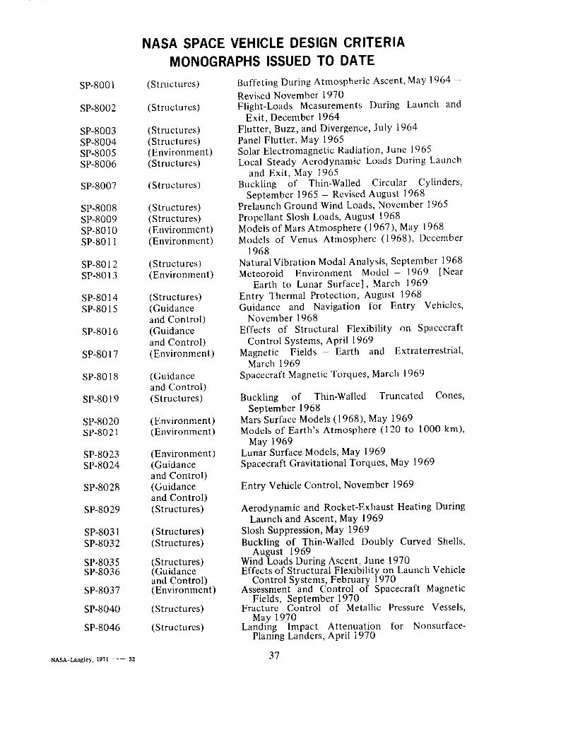
NASA SPACE VEHICLE DESIGN CRITERIA
MONOGRAPHS ISSUED TO DATE
SP-8001
SP-8002
SP-8003SP-8004SP-8005SP-8006
SP-8007
SP-8008SP-8009SP-8010SP-8011
SP-8012SP-8013
SP-8014SP-8015
SP-8016
SP-8017
SP-8018
SP-8019
SP-8020SP-8021
SP-8023SP-8024
SP-8028
SP-8029
SP-8031SP-8032
SP-8035SP-8036
SP-8037
SP-8040
SP-8046
(Structures)
(Structures)
(Structures)(Structures)(Environment)(Structures)
(Structures)
(Structures)(Structures)(Environment)(Environment)
(Structures)(Environment)
(Structures)(Guidanceand Control)
(Guidanceand Control)
(Environment)
(Guidanceand Control)
(Structures)
(Environment)(Environment)
(Environment)(Guidanceand Control)(Guidanceand Control)
(Structures)
(Structures)
(Structures)
(Structures)(Guidanceand Control)(Environment)
(Structures)
(Structures)
Buffeting During Atmospheric Ascent, May 1964 -
Revised November 1970Flight-Loads Measurements During Launch and
Exit, December 1964Flutter, Buzz, and Divergence, July 1964Panel Flutter, May 1965Solar Electromagnetic Radiation, June 1965Local Steady Aerodynamic Loads During Launch
and Exit, May 1965Buckling of Thin-Walled Circular Cylinders,
September 1965 - Revised August 1968Prelaunch Ground Wind Loads, November 1965
Propellant Slosh Loads, August 1968Models of Mars Atmosphere (1967), May 1968Models of Venus Atmosphere (1968), December
1968Natural Vibration Modal Analysis, September 1968Meteoroid Environment Model- 1969 [Near
Earth to Lunar Surface], March 1969
Entry Thermal Protection, August 1968Guidance and Navigation for Entry Vehicles,
November 1968Effects of Structural Flexibility on Spacecraft
Control Systems, April 1969
Magnetic Fields - Earth and Extraterrestrial,March 1969
Spacecraft Magnetic Torques, March 1969
Buckling of Thin-Walled Truncated Cones,September 1968
Mars Surface Models (1968), May 1969Models of Earth's Atmosphere (120 to 1000 km),
May 1969Lunar Surface Models, May 1969Spacecraft Gravitational Torques, May 1969
Entry Vehicle Control, November 1969
Aerodynamic and Rocket-Exhaust Heating DuringLaunch and Ascent, May 1969
Slosh Suppression, May 1969
Buckling of Thin-Walled Doubly Curved Shells,August 1969
Wind Loads During Ascent, June 1970Effects of Structural Flexibility on Launch Vehicle
Control Systems, February 1970Assessment and Control of Spacecraft Magnetic
Fields, September 1970Fracture Control of Metallic Pressure Vessels,
May 1970Landing Impact Attenuation for Nonsurface-
Planing Landers, April i970
NASA-Langley, 1971 -- 32 37


NATIONAL AERONAUTICS AND SPACE ADMINISTRA]ION
WASHINGTON, D.C. 20546
OFFICIAL BUSINESS FIRST CLASS MAIL
POSTAGE AND FEES PAID
NATIONAL AERONAUTICS AND
SPACE ADMINISTRATION
If Undeliverable (Section 15 8POSTMASTER: Postal Manual) Do Not Return