structure of mechanically agitated gas-liquid contactors · helical coil helical coil hair pin coil...
TRANSCRIPT
MULTIPLE IMPELLER GAS-LIQUID CONTACTORS138
7 Heat Transfer
Controlling the system temperature within a narrow limit is a common process
requirement in many industrial practices, and heat transfer in a process vessel can be greatly
improved by applying a mechanical agitation. Although there are numerous experimental
correlations available for predicting the values of heat transfer coefficients, the range of
application is usually limited for the specific cases. Because heat transfer coefficient is
affected by so many factors, such as fluid properties, hydrodynamics generated by the
impeller and arrangements of coil and baffles. Therefore, it is still difficult to have a general
correlation to estimate heat transfer correctly for all purposes.
This chapter will be devoted to give a brief review of the current researches in heat
transfer in gassed multiple impeller stirred vessels along with our own studies on both local
and overall heat transfer coefficients in stirred vessels to illustrate how gassing will affect the
heat transfer in a mechanically agitated vessel.
7.1 Heat transfer coefficient
The amount of heat transferred from process fluid to heat transfer medium through heat
transfer surface can be estimated by:
Q=UA∆Tm (7.1-1)
where U=overall heat transfer coefficient (w Km°/ )
A=Heat transfer area ( 2m )
Tm =log. mean temperature difference between process fluid and heat
transfer medium ( K° )
The reciprocal value of U is a sum of a series of heat transfer resistances and can be
written as:
c2
1
2m1
RAA
h1
kh1
U1
+++=l (7.1-2)
here, h1 denotes process fluid side heat transfer film coefficient, h2 is film coefficient at heat
transfer medium side, l/km is conductive thermal resistance of heat transfer surface material
and Rc is the resistance due to fouled dirt. In many cases h1 is the limiting resistance, however,
Heat Transfer 139
for the low viscosity process fluids, and flow velocity of the heat transfer medium in jacket or
coil is very low, h2 will often become the limiting resistance of the system.
Since the film heat transfer coefficient expresses thermal conductivity of the boundary
layer clinging on the heat transfer surface, the thickness of this boundary layer directly affects
the rate of heat transfer through this layer. Thus, prior to grasp the performance of heat
transfer of a stirred vessel, it needs to understand the hydrodynamics of process fluid within
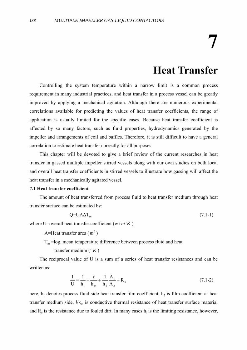
the system. Figure 7.1-1 depicts the different flow patterns in mechanical agitated vessel
generated by 45° pitched paddle and Rushton turbine impellers under various arrangements of
coils and baffles. These different flows against heat transfer surface naturally result in
different local heat transfer characteristics for the process vessels.
Rushton
Turbine
Pitched
Blade paddle
helical coil helical coil hair pin coil baffles
without baffles with baffles
Fig. 7.1-1 Flow patterns of the disk turbine and the pitch paddle impeller systems withvarious internal structures.
7.2 Local heat transfer coefficient
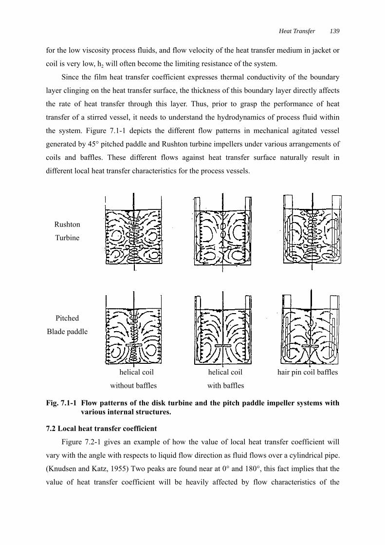
Figure 7.2-1 gives an example of how the value of local heat transfer coefficient will
vary with the angle with respects to liquid flow direction as fluid flows over a cylindrical pipe.
(Knudsen and Katz, 1955) Two peaks are found near at 0° and 180°, this fact implies that the
value of heat transfer coefficient will be heavily affected by flow characteristics of the
MULTIPLE IMPELLER GAS-LIQUID CONTACTORS140
impeller and arrangement of the heat transfer surface. Due to the complex characteristic of the
flow pattern existed in stirred vessels, there have been only a few studies devoted to local
process side heat transfer.
Fig.7.2-1 Variation of heat transfer coefficient with respect to flow direction.
Using an electrochemical technique, Mann (1985) analogized the results of local
variation of the mass transfer coefficient to heat transfer. Karcz and Strek (1985) used the
same technique in an aerated stirred vessel with a dual turbine system. Using a micro foil
sensor, Fasano et al. (1991) and Haam and Brodkey (1992) also determined local heat transfer
coefficients for side wall and bottom surface. Instead of correlating the dimensionless local
heat transfer coefficient Nu as a function of power drawn by an impeller, they correlated Nu
in terms of the dimensionless superficial velocity of gas.
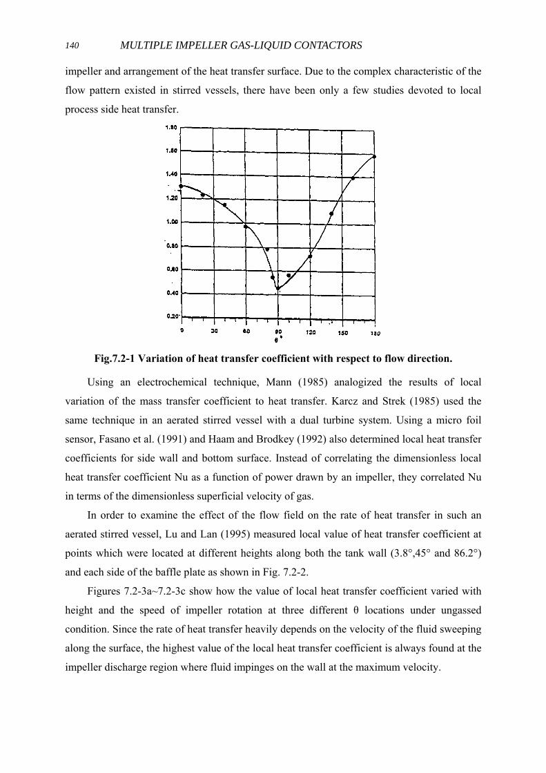
In order to examine the effect of the flow field on the rate of heat transfer in such an
aerated stirred vessel, Lu and Lan (1995) measured local value of heat transfer coefficient at
points which were located at different heights along both the tank wall (3.8°,45° and 86.2°)
and each side of the baffle plate as shown in Fig. 7.2-2.
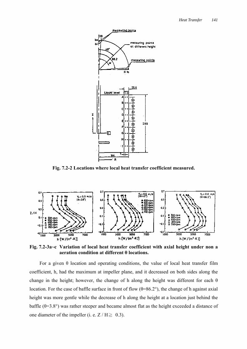
Figures 7.2-3a~7.2-3c show how the value of local heat transfer coefficient varied with
height and the speed of impeller rotation at three different θ locations under ungassed
condition. Since the rate of heat transfer heavily depends on the velocity of the fluid sweeping
along the surface, the highest value of the local heat transfer coefficient is always found at the
impeller discharge region where fluid impinges on the wall at the maximum velocity.
Heat Transfer 141
Fig. 7.2-2 Locations where local heat transfer coefficient measured.
Fig. 7.2-3a~c Variation of local heat transfer coefficient with axial height under non aaeration condition at different θ locations.
For a given θ location and operating conditions, the value of local heat transfer film
coefficient, h, had the maximum at impeller plane, and it decreased on both sides along the
change in the height; however, the change of h along the height was different for each θ
location. For the case of baffle surface in front of flow (θ=86.2°), the change of h against axial
height was more gentle while the decrease of h along the height at a location just behind the
baffle (θ=3.8°) was rather steeper and became almost flat as the height exceeded a distance of
one diameter of the impeller (i. e. Z / H≧ 0.3).
MULTIPLE IMPELLER GAS-LIQUID CONTACTORS142
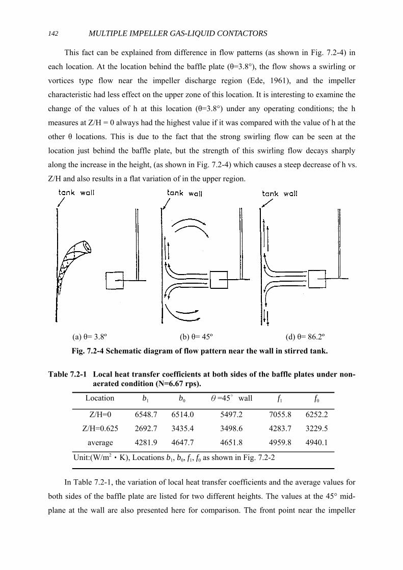
This fact can be explained from difference in flow patterns (as shown in Fig. 7.2-4) in
each location. At the location behind the baffle plate (θ=3.8°), the flow shows a swirling or
vortices type flow near the impeller discharge region (Ede, 1961), and the impeller
characteristic had less effect on the upper zone of this location. It is interesting to examine the
change of the values of h at this location (θ=3.8°) under any operating conditions; the h
measures at Z/H = 0 always had the highest value if it was compared with the value of h at the
other θ locations. This is due to the fact that the strong swirling flow can be seen at the
location just behind the baffle plate, but the strength of this swirling flow decays sharply
along the increase in the height, (as shown in Fig. 7.2-4) which causes a steep decrease of h vs.
Z/H and also results in a flat variation of in the upper region.
(a) θ= 3.8º (b) θ= 45º (d) θ= 86.2º
Fig. 7.2-4 Schematic diagram of flow pattern near the wall in stirred tank.
Table 7.2-1 Local heat transfer coefficients at both sides of the baffle plates under non-aerated condition (N=6.67 rps).
Location b1 b0 θ=45∘wall f1 f0
Z/H=0
Z/H=0.625
average
6548.7
2692.7
4281.9
6514.0
3435.4
4647.7
5497.2
3498.6
4651.8
7055.8
4283.7
4959.8
6252.2
3229.5
4940.1
Unit:(W/m2‧K), Locations b1, b0, f1, f0 as shown in Fig. 7.2-2
In Table 7.2-1, the variation of local heat transfer coefficients and the average values for
both sides of the baffle plate are listed for two different heights. The values at the 45° mid-
plane at the wall are also presented here for comparison. The front point near the impeller

Heat Transfer 143
always has the highest local heat transfer coefficient and also the highest mean value. On the
backside of the baffle plate, the value of local h at the impeller discharge region shows to be
quite high, but it becomes almost the lowest value in the region near the free surface. It is
noticed that the average value of the mean heat transfer coefficient for the whole only
approximately 10% higher than that obtained at the 45° mid-plane.
7.3 Effect of gassing rates on heat transfer
Since the boundary layer thickness is directly affected by flow which sweeps over the
surface, local heat transfer coefficient in gassed stirred vessels can be related to flow patterns
of both liquid and bubbles. At low sparged rates, the impeller performs nearly equal to non-
gassed condition that pumps liquids and disperses gas radially. This action results a maximum
value of h in impeller plane. As gassing rate increases, the dispersed bubbles will be trapped
in the vicinity of the impeller. This weakens the pumping capacity and reduces the value of
local heat transfer coefficient.
Figure 7.3-1 shows a plot of h vs. VS for a jacket vessel obtained by Kurpiers et. al.
(1985). For a given rotational speed of the impeller, hj reduces first as the VS increases due to
its reduction in pumping capacity. As the value of h reaches to a minimum value, the heat
transfer will shift from agitation limiting to gassing controlling situation and the plot will
merge with the results obtained from bubble columns.
Fig. 7.3-1 Influence of aeration intensity on heat transfer. (Kurpiers et.al.,1985).
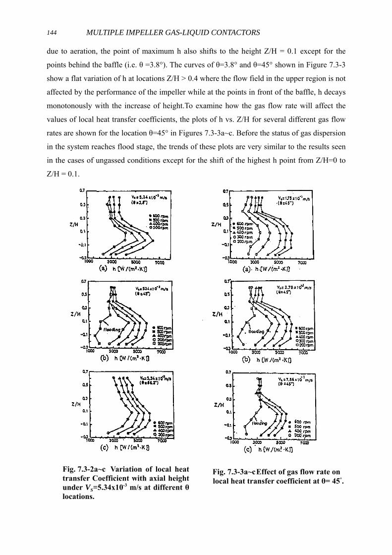
In Figures 7.3-2a~7.3-2c, how the value of h varies with height and rotational speeds for
a considerable high gas flow rate of Vs = 0.00534 m/s (equivalent to 1.11 VVM) at three
different θ locations are shown. Since the location of maximum liquid velocity shifts upward
MULTIPLE IMPELLER GAS-LIQUID CONTACTORS144
due to aeration, the point of maximum h also shifts to the height Z/H = 0.1 except for the
points behind the baffle (i.e. θ =3.8°). The curves of θ=3.8° and θ=45° shown in Figure 7.3-3
show a flat variation of h at locations Z/H > 0.4 where the flow field in the upper region is not
affected by the performance of the impeller while at the points in front of the baffle, h decays
monotonously with the increase of height.To examine how the gas flow rate will affect the
values of local heat transfer coefficients, the plots of h vs. Z/H for several different gas flow
rates are shown for the location θ=45° in Figures 7.3-3a~c. Before the status of gas dispersion
in the system reaches flood stage, the trends of these plots are very similar to the results seen
in the cases of ungassed conditions except for the shift of the highest h point from Z/H=0 to
Z/H = 0.1.
Fig. 7.3-2a~c Variation of local heattransfer Coefficient with axial heightunder VS=5.34x10⁻³ m/s at different θlocations.
Fig. 7.3-3a~cEffect of gas flow rate onlocal heat transfer coefficient at θ= 45°.
Heat Transfer 145
If the gas flow rate continuously increases, or the rotational speed of the impeller
decreases to have a flooding situation, there occurs a sharp decrease in the value of h in the
place near the impeller due to insufficient pumping of the impeller.
For a given rotational speed, no significant change in the upper region of the tank is
observed because the flow of fluid in this region is not much affected by the pumping
capability of impeller, but the up rising gas flow rates.
7.4 Average Heat Transfer Coefficients
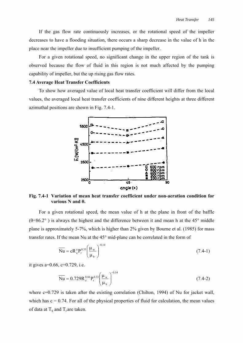
To show how averaged value of local heat transfer coefficient will differ from the local
values, the averaged local heat transfer coefficients of nine different heights at three different
azimuthal positions are shown in Fig. 7.4-1.
Fig. 7.4-1 Variation of mean heat transfer coefficient under non-aeration condition forvarious N and θ.
For a given rotational speed, the mean value of h at the plane in front of the baffle
(θ=86.2° ) is always the highest and the difference between it and mean h at the 45° middle
plane is approximately 5-7%, which is higher than 2% given by Bourne et al. (1985) for mass
transfer rates. If the mean Nu at the 45° mid-plane can be correlated in the form of140
b
w330r
ae PcRNu
..
−
⎟⎟⎠
⎞⎜⎜⎝
⎛µµ
= (7.4-1)
it gives a=0.66, c=0.729, i.e.140
b
w330r
660e PR7290Nu
....
−
⎟⎟⎠
⎞⎜⎜⎝
⎛µµ
= (7.4-2)
where c=0.729 is taken after the existing correlation (Chilton, 1994) of Nu for jacket wall,
which has c = 0.74. For all of the physical properties of fluid for calculation, the mean values
of data at TS and Tf are taken.
MULTIPLE IMPELLER GAS-LIQUID CONTACTORS146
7.5 Correlation of Nu with Dimensionless Variables for Aerated System
Loiseau and Charpentier (1977) indicated that Michel and Millers experimental equation
(Michel and Miller, 1962)
46.056.0
g
3o
g )QNDP
(83.0P = (7.5-1)
can be used to estimate the gassed power drawn by a Rushton turbine impeller m its standard
geometry, with a gas flow rate of 0.0005m/s≦Vs≦0.09m/s and 1<PoND3/Qg0.56<107. For an
ungassed system, Calderbank and Moo-Young (1961) deduced from local isotropic turbulent
and proposed that3/14/1
v/p PrReNu = (7.5-2)
to correlate the heat transfer coefficient with the power drawn by the impeller for a stirred
vessel, where Rep/v is a modified Reynolds number and is defined as
3
24
v/pT)V/P(Re
µρ
= (7.5-3)
Modifying Eq. 7.5-2 by inserting (µw /µb)0.14 to include the effect of viscosity, it can be written
in the form of
14.0
b
w3/1r
aV/P P)(RecNu
−
⎟⎟⎠
⎞⎜⎜⎝
⎛µµ
= (7.5-4)
Since in most operations, the status of gas dispersion is either at loading or complete
dispersion, which satisfies the condition Pg>>Pa (aeration power) or P/V≒Pg/V, it follows that324
gv/p /T)V/P(Re µρ≈ (7.5-5)
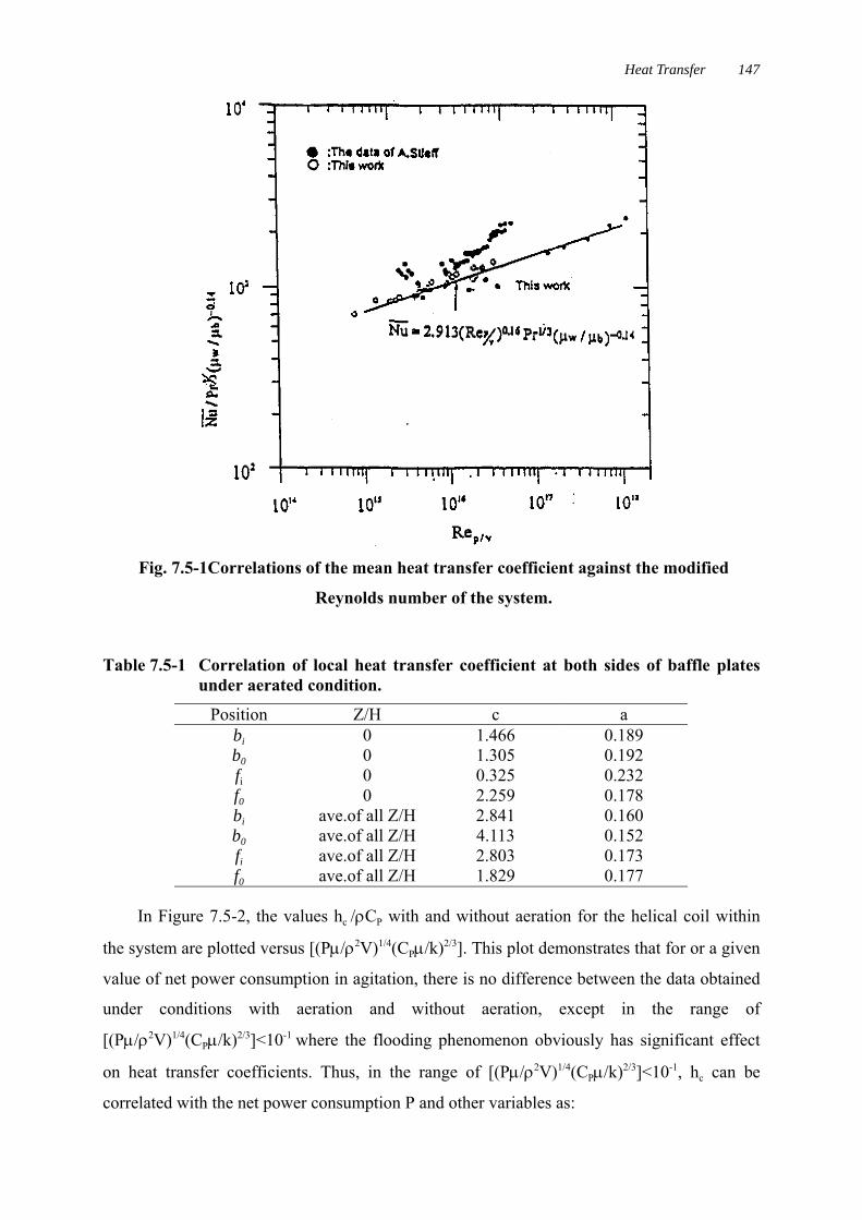
Figure 7.5-1 shows a plot of Nu at 45° mid-plane for air-water system, and they are
compared with the data of Steiff et al.(1985). These results can be correlated as14.0
b
w33.0r
16.0V/P PRe913.2Nu
−
⎟⎟⎠
⎞⎜⎜⎝
⎛µµ
= (7.5-6)
for the range of 7.6 x 10¹⁴ < Rep/v < 3 × 10¹⁶.
Table 7.5-1 lists the values of constants for the same correlation for local and mean heat
transfer coefficients measured at both sides of the baffle plates. For the whole baffle, the
average value of Nu for air-water system can be given as14.0
b
w33.0r
129.0V/P PRe8.9Nu
−
⎟⎟⎠
⎞⎜⎜⎝
⎛µµ
= (7.5-7)
Heat Transfer 147
Fig. 7.5-1Correlations of the mean heat transfer coefficient against the modified
Reynolds number of the system.
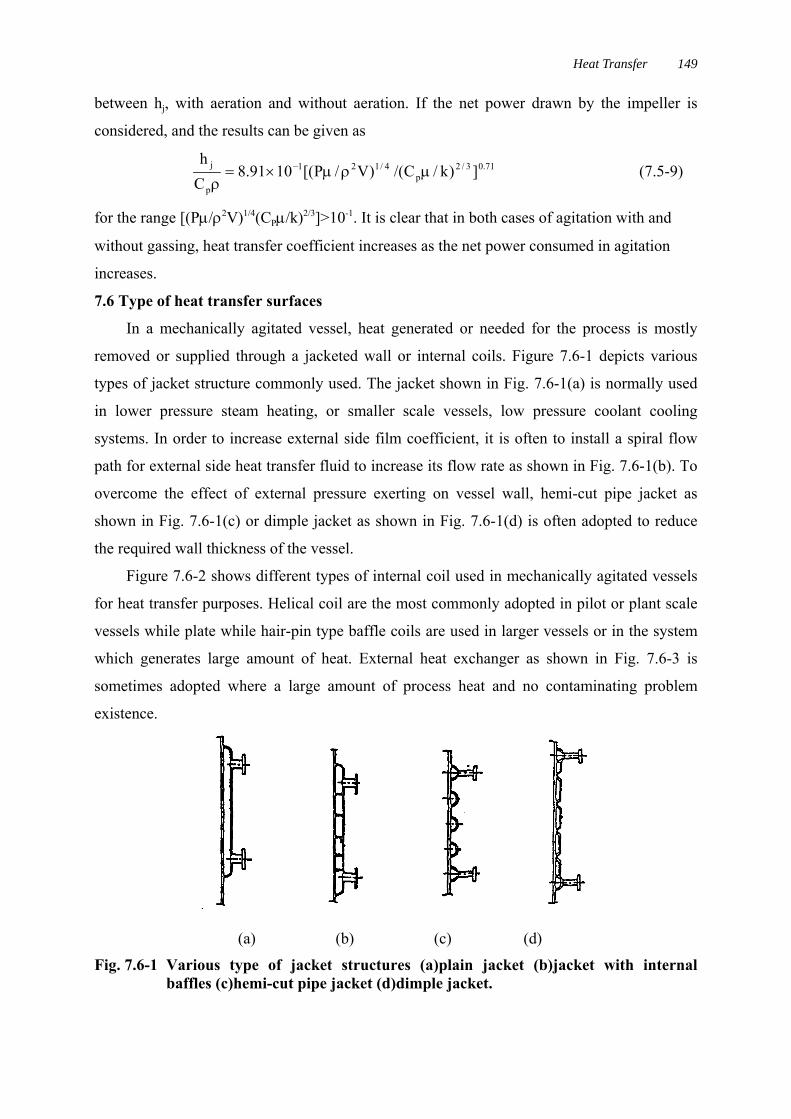
Table 7.5-1 Correlation of local heat transfer coefficient at both sides of baffle platesunder aerated condition.
Position Z/H c abi 0 1.466 0.189b0 0 1.305 0.192fi 0 0.325 0.232f0 0 2.259 0.178bi ave.of all Z/H 2.841 0.160b0 ave.of all Z/H 4.113 0.152fi ave.of all Z/H 2.803 0.173f0 ave.of all Z/H 1.829 0.177
In Figure 7.5-2, the values hc /ρCP with and without aeration for the helical coil within
the system are plotted versus [(Pµ/ρ2V)1/4(CPµ/k)2/3]. This plot demonstrates that for or a given
value of net power consumption in agitation, there is no difference between the data obtained
under conditions with aeration and without aeration, except in the range of
[(Pµ/ρ2V)1/4(CPµ/k)2/3]<10-1 where the flooding phenomenon obviously has significant effect
on heat transfer coefficients. Thus, in the range of [(Pµ/ρ2V)1/4(CPµ/k)2/3]<10-1, hc can be
correlated with the net power consumption P and other variables as:

MULTIPLE IMPELLER GAS-LIQUID CONTACTORS148
])k/C/()V/P[(1054.2Ch 3/2
p4/121
p
c µρµ×=ρ
− ( 7.5-8 )
Fig. 7.5-2 Heat transfer coefficient of coil in agitated vessel with dimenlsionlessvariables.
Fig. 7.5-3 hj in agitated vessel with and without aeration correlated in term of the netimpeller power consumption.
A similar plot of the heat transfer coefficient from jacket surface to the liquid vs. the
power consumed in agitation with and without gassing is summarized in Figure 7.5-3. Here P
again denotes net power drawn by the impeller either with or without gassing. The experiment
values in this figure show that for the same power consumption, there is no distinction
Heat Transfer 149
between hj, with aeration and without aeration. If the net power drawn by the impeller is
considered, and the results can be given as
71.03/2p
4/121
p
j ])k/C/()V/P[(1091.8Ch
µρµ×=ρ
− (7.5-9)
for the range [(Pµ/ρ2V)1/4(CPµ/k)2/3]>10-1. It is clear that in both cases of agitation with and
without gassing, heat transfer coefficient increases as the net power consumed in agitation
increases.
7.6 Type of heat transfer surfaces
In a mechanically agitated vessel, heat generated or needed for the process is mostly
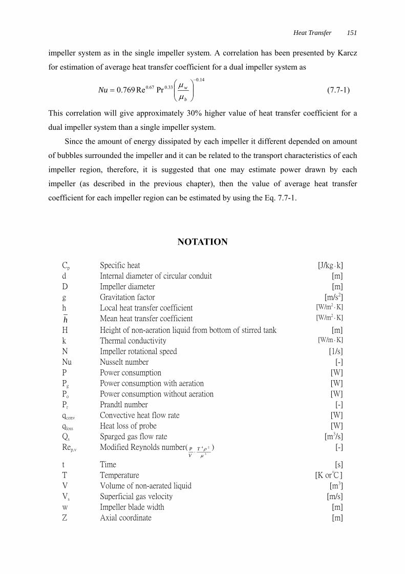
removed or supplied through a jacketed wall or internal coils. Figure 7.6-1 depicts various
types of jacket structure commonly used. The jacket shown in Fig. 7.6-1(a) is normally used
in lower pressure steam heating, or smaller scale vessels, low pressure coolant cooling
systems. In order to increase external side film coefficient, it is often to install a spiral flow
path for external side heat transfer fluid to increase its flow rate as shown in Fig. 7.6-1(b). To
overcome the effect of external pressure exerting on vessel wall, hemi-cut pipe jacket as
shown in Fig. 7.6-1(c) or dimple jacket as shown in Fig. 7.6-1(d) is often adopted to reduce
the required wall thickness of the vessel.
Figure 7.6-2 shows different types of internal coil used in mechanically agitated vessels
for heat transfer purposes. Helical coil are the most commonly adopted in pilot or plant scale
vessels while plate while hair-pin type baffle coils are used in larger vessels or in the system
which generates large amount of heat. External heat exchanger as shown in Fig. 7.6-3 is
sometimes adopted where a large amount of process heat and no contaminating problem
existence.
(a) (b) (c) (d)
Fig. 7.6-1 Various type of jacket structures (a)plain jacket (b)jacket with internalbaffles (c)hemi-cut pipe jacket (d)dimple jacket.

MULTIPLE IMPELLER GAS-LIQUID CONTACTORS150
(a) helical coil (b) hair pinbaffle coils
Fig. 7.6-2 Internal coils.
Fig. 7.6-3 Agitated vessel with externalheat exchanger.
7.7 Heat Transfer in Multiple Impeller Systems
The study on the heat transfer in multiple impeller systems is scare and limited to dual
impeller systems. Fig. 7.7-1 shows a plot of local heat transfer coefficient vs. height for
various gassing rate obtained by Karcz (1999), the largest amount of the heat transfer occurs
at the impeller discharge planes and the heat transfer coefficient decreases with the increase of
aeration rate.
Fig. 7.7-1 Variation of local of local heat transfer rate along the axial location in theaxial location in a dual impeller stirred vessel under various gassing rate.
The plots also shown that the higher heat transfer coefficient was found at the upper
impeller region than it was seen at the bottom impeller region. This is due to less air flow
through the upper impeller. Kurpiers et al. (1986) has explained the heat transfer in stirred
vessels by adopting Higbie’s penertration theory. Without examining the net power drawn by
each impeller, they concluded that it was difficult to estimate heat transfer rate in dual
Heat Transfer 151
impeller system as in the single impeller system. A correlation has been presented by Karcz
for estimation of average heat transfer coefficient for a dual impeller system as14.0
33.067.0 PrRe769.0−
⎟⎟⎠
⎞⎜⎜⎝
⎛=
b
wNuµµ
(7.7-1)
This correlation will give approximately 30% higher value of heat transfer coefficient for a
dual impeller system than a single impeller system.
Since the amount of energy dissipated by each impeller it different depended on amount
of bubbles surrounded the impeller and it can be related to the transport characteristics of each
impeller region, therefore, it is suggested that one may estimate power drawn by each
impeller (as described in the previous chapter), then the value of average heat transfer
coefficient for each impeller region can be estimated by using the Eq. 7.7-1.
NOTATION
Cp Specific heat [J/kg‧k]
d Internal diameter of circular conduit [m]
D Impeller diameter [m]
g Gravitation factor [m/s2]
h Local heat transfer coefficient [W/m2‧K]
h Mean heat transfer coefficient [W/m2‧K]
H Height of non-aeration liquid from bottom of stirred tank [m]
k Thermal conductivity [W/m‧K]
N Impeller rotational speed [1/s]
Nu Nusselt number [-]
P Power consumption [W]
Pg Power consumption with aeration [W]
Po Power consumption without aeration [W]
Pr Prandtl number [-]
qconv Convective heat flow rate [W]
qloss Heat loss of probe [W]
Qs Sparged gas flow rate [m3/s]
Rep.v Modified Reynolds number(3
24
µρT
VP⋅
) [-]
t Time [s]
T Temperature [K or℃]
V Volume of non-aerated liquid [m3]
Vs Superficial gas velocity [m/s]
w Impeller blade width [m]
Z Axial coordinate [m]
MULTIPLE IMPELLER GAS-LIQUID CONTACTORS152
<Greeks Letters>α Thermal diffusivity [m2/s]
θ Shaft angular position [degree]
μ Fluid viscosity [Pa‧s]
μb Fluid viscosity at bulk fluid temperature [Pa‧s]
μw Fluid viscosity at wall temperature [Pa‧s]
ν Kinematic viscosity [m2/s]
ρ Fluid density [kg/m3]
ω Angular velocity [rad/s]
<Subscripts>c Coil
co Correlated
G Gas
j Jacket
L Liquid
<Dimensionless groups>Nu Local Nusselt number LkTh /⋅
Nu Mean Nusselt numberLkTh /⋅
Pr Prandtl number α/vRe Reynolds number vDN /2⋅Rep/v Modified Reynolds number 324 /)/( µρ⋅⋅TVP