structured cabling for voice and data - inside-plant
TRANSCRIPT

STRUCTURED CABLING FOR VOICE AND DATA - INSIDE-PLANT216043.00 271005 - 1
SECTION 271005
STRUCTURED CABLING FOR VOICE AND DATA - INSIDE-PLANTPART 1 GENERAL1.01 SECTION INCLUDES
A. Communications system design requirements.B. Communications pathways.C. Copper cable and terminations.D. Communications identification.E. Communications DemolitionF. Voice CablingG. Data CablingH. Fiber Optic CablingI. Open RacksJ. Enclosed RacksK. Wall Mounted RacksL. Ladder Rack RunwayM. Distribution frames, cross-connection equipment, enclosures, and outlets.
1.02 DEFINITIONSA. BICSI: Building Industry Consulting Service International.B. Cross-Connect: A facility enabling the termination of cable elements and their
interconnection or cross-connection.C. EMI: Electromagnetic interference.D. IDC: Insulation displacement connector.E. Ladder Rack: A fabricated structure consisting of two longitudinal side rails connected
by individual transverse members (rungs).F. LAN: Local area network.G. Outlet/Connectors: A connecting device in the work area on which horizontal cable or
outlet cable terminates.H. RCDD: Registered Communications Distribution Designer.I. UTP: Unshielded twisted pair.
1.03 COODRINATION OF WORKA. Contractor shall furnish and install all conduit/raceway as required for the structured
cabling distribution system. This includes all raceway explicitly shown on plans orgenerically required for a complete, functional system.
B. Contractor shall furnish and install all specialty backboxes for devices as required forthe structured cabling distribution system. This includes all backboxes explicitly shownon plans or generically required for a complete, functional system.

STRUCTURED CABLING FOR VOICE AND DATA - INSIDE-PLANT217085.00 271005 - 2
C. Contractor shall furnish and install all branch circuits required for the structuredcabling distribution system as specified. This includes all circuits explicitly shown onplans or generically required for a complete, functional system.
1.04 REFERENCE STANDARDSA. American National Standards Institute/Telecommunications Industry
Association/Electronic Industries Alliance (ANSI/TIA/EIA) ANSI/TIA/EIA-568-B.1Commercial Building Telecommunications Cabling Standards Part 1: GeneralRequirements, and all associated addenda.
B. ICEA S-90-661 - Category 3, 5, & 5e Individually Unshielded Twisted Pair IndoorCables (With or Without An Overall Shield) For Use in General Purpose and LANCommunications Wiring Systems Technical Requirements; 2012.
C. Chicago Building Code - Most Recent Edition.D. NFPA 70 - National Electrical Code; Most Recent Edition Adopted by Authority Having
Jurisdiction, Including All Applicable Amendments and Supplements.E. IAC 180 - Illinois Administrative Code 180.F. TIA-492AAAB-A - Detail Specification for 50-um Core Diameter/125-um Cladding
Diameter Class Ia Graded-Index Multimode Optical Fibers; Rev A, 2009.G. TIA-492CAAA - Detail Specification for Class IVa Dispersion-Unshifted Single-Mode
Optical Fibers; 1998 (R 2002).H. TIA-526-7 - Measurement of Optical Power Loss of Installed Single-Mode Fiber Cable
Plant; Rev A, 2015.I. TIA-526-14 - Optical Power Loss Measurement of Installed Multimode Fiber Cable
Plant; Rev C, 2015.J. TIA-568 (SET) - Commercial Building Telecommunications Cabling Standard Set;
2015.K. TIA-568-C.2 - Balanced Twisted-Pair Telecommunications Cabling and Components
Standards; Rev C, 2009 (with Addenda; 2014).L. TIA/EIA-568-B.3 - Commercial Building Telecommunications Cabling Standard - Part
3: Optical Fiber Cabling Components Standard, and Addendum 1 - AdditionalTransmission Performance Specifications for 50/125 um Optical Fiber Cables; Rev B,2000; Addendum 1.
M. TIA-569-C - Commercial Building Standard for Telecommunications Pathways andSpaces; Rev C, 2012 (with Addenda; 2013).
N. TIA-606-B - Administration Standard for the Telecommunications Infrastructure; RevB, 2012.
O. TIA-607-B - Generic Telecommunications Bonding and Grounding (Earthing) forCustomer Premises; Rev B, 2012 (with Addenda; 2013).
P. ANSI/J-STD-607 - Commercial Building Grounding (Earthing) and BondingRequirements for Telecommunications; Rev A, 2002.
Q. ANSI/TIA/EIA-526 Standard Test Procedures for Fiber Optic Systems, and allassociated addenda.

STRUCTURED CABLING FOR VOICE AND DATA - INSIDE-PLANT217085.00 271005 - 3
R. ANSI/TIA/EIA-758 Customer-Owned Outside Plant Telecommunications CablingStandard, and all associated addenda.
S. International Standards Organization/International Electrotechnical Commission(ISO/IEC) DIS 11801, January 6, 1994
T. American National Standards Institute (ANSI) X3T9.5 Requirements for UTP at 100Mbps
U. UL 444 - Communications Cables; Current Edition, Including All Revisions.V. UL 497 - Standard for Protectors for Paired-Conductor Communications Circuits;
Current Edition, Including All Revisions.W. EIA-310-D - Cabinets, Racks, Panels, and Associated Equipment; Electronic
Industries Association; 1992X. UL 50, Cabinets and BoxesY. UL 1581 - Reference Standard for Electrical Wires, Cables, and Flexible Cords;
Current Edition, Including All Revisions.Z. UL 1863 - Communications-Circuit Accessories; Current Edition, Including All
Revisions.AA. Work performed should additionally comply with and follow guidelines established in
the latest edition/revision, as of the date of the Contract Documents, of the followingpublications:1. BICSI Telecommunications Distribution Methods Manual (TDMM)2. BICSI Customer-Owned Outside Plant (CO-OSP)3. American National Standards Institute/National Electrical Contractors
Association/Building Industry Consulting Service International(ANSI/NECA/BICSI) 568-2001 Standard for Installing Commercial BuildingTelecommunications Cabling
1.05 SUBMITTALSA. General:
1. Reviews of submittals are to establish general conformance to design intent anddoes not waive contract requirements. Contractor is responsible for dimensions,quantities, mounting accessories, methods of construction, and compliance withthe Contract Documents.
2. Provide separate submittal product data/shop drawings for each fixture, device, and equipment type clearly indicating the type designation per the ContractDocuments and all pertinent options and accessories. Do not group similarfixture types together on a single cut sheet. Submittals which do not indicateoption data where multiple selections exist will be returned without beingreviewed.
B. Product Data: Provide manufacturer's standard catalog pages and data sheets foreach product.1. Storage and handling requirements and recommendations.2. Installation methods.
C. Shop Drawings: Show compliance with requirements on isometric schematic diagramof network layout, showing cable routings, telecommunication closets, rack and

STRUCTURED CABLING FOR VOICE AND DATA - INSIDE-PLANT217085.00 271005 - 4
enclosure layouts and locations, service entrance, and grounding, prepared andapproved by BICSI Registered Communications Distribution Designer (RCDD).1. System Labeling Schedules: Electronic copy of proposed labeling schedules and
identification plates, in software and format selected by Owner.2. Cabling administration drawings and printouts.
D. Evidence of qualifications for installer.E. Test Plan: Complete and detailed plan, with list of test equipment, procedures for
inspection and testing. Submit along with product data. ______F. Field Test Reports.G. Project Record Documents: Prepared and approved by BICSI Registered
Communications Distribution Designer (RCDD).1. Record actual locations of outlet boxes and distribution frames.2. Show as-installed color coding, pair assignment, polarization, and cross-connect
layout.3. Identify distribution frames and equipment rooms by room number on contract
drawings.H. Operation and Maintenance Data: List of all components with part numbers, sources
of supply, and operation and maintenance instructions; include copy of project recorddocuments.
1.06 QUALITY ASSURANCEA. Conform to requirements of The City of Chicago Building Code.B. Conform to requirements of NFPA 70.C. Conform to Illinois Administrative Code 180 and all building codes as listed in IAC
section 180.60.D. Installer Qualifications: Cabling Installer must have personnel certified by BICSI on
staff. Engage an experienced contractor who:1. Shall be fully capable and experienced in the installation of the communications
systems specified, and have a minimum of five (5) years experience on similarsystems.
2. Has BICSI-trained and -certified, or equally qualified and certified, installers andtechnicians on staff and assign them to this project. If personnel of Contractorare not BICSI-trained and -certified, Contractor to submit with bid all necessarycredentials and certificates of training for personnel staff for evaluation anddetermination by CPS OTS Sr. Infrastructure Manager that said credentials andcertificates are equal to BICSI standards. The project shall be staffed at all timesby Installers and Technicians who, in the role of lead crafts persons, will be ableto provide leadership and technical resources for the remaining crafts persons onthe project.
3. Shall be certified by the manufacturing company(-ies) in all aspects of installationand testing of the products described within the telecommunications systemsspecifications. Specifically, those manufacturer(s) whose components constitutea component of the structured cabling system(s) installed as part of the voice anddata transport systems. Said certification is to be such that the Contractor is ableto offer and fully comply with the requirements to provide Owner with an extendedwarranty as defined in “System Warranty and Application Assurance” Article ofthis Section.
STRUCTURED CABLING FOR VOICE AND DATA - INSIDE-PLANT217085.00 271005 - 5
E. Installer Supervision:1. The selected Contractor shall provide a Project Manager to act a single point of
contact for all activities performed under this section. The Project Manager shallbe a Registered Communications Distribution Designer (RCDD). The RCDD shallhave a minimum of 3 years experience in design and installation. The designermust have sufficient experience in this type project(s) as to be able to lendadequate technical support to the field forces during installation, during thewarranty period and during any extended warranty periods or maintenancecontracts. The Contractor must attach a resume of the responsible designer tothe Contractor's response for evaluation.
2. The Project Manager, or designee thereof, shall be required to attend projectmeetings as required until project closeout/signoff.
3. Should the Project Manager assigned to this project change during theinstallation, the new Project Manager assigned must meet all qualifications statedin this section, and must also submit a resume for review by the Owner.
4. If, in the opinion of the Owner, the Project Manager does not possess adequatequalifications to support the project, the Owner reserves the right to require theContractor to assign a designer whom, in the Owner's opinion, possesses thenecessary skills and experience required of this project.
F. Materials and equipment shall be the standard product of a manufacturer regularlyengaged in the production of the required type of material or equipment for at leastfive years (unless specifically exempted by the Owner) and shall be themanufacturer's latest design with published properties.
G. Source Limitations: Equipment and materials of the same general type shall be of thesame manufacture throughout the project to provide uniform appearance, operationand maintenance.
H. Equipment and materials shall be without blemish or defect.I. Electrical Components, Devices, and Accessories: Listed and labeled as defined in
City of Chicago Electrical Code, by a qualified testing agency, and marked forintended location and application.
J. Comply with NFPA 70 for abandoned cabling.1.07 DELIVERY, STORAGE, AND HANDLING
A. Environmental Limitations: Do not deliver or install cables and connecting materialsuntil wet work in spaces is complete and dry, and HVAC system is operating andmaintaining ambient temperature and humidity conditions at occupancy levels duringthe remainder of the construction period.
B. Do not deliver or install equipment frames and ladder rack until spaces are enclosedand weathertight, wet work in spaces is complete and dry, and work above ceilings iscomplete.
C. Receive, handle, and store communications system items and materials at the projectsite. Materials and items shall be placed so that they are protected from damage anddeterioration.
D. Stage materials in a secure area of the project site until installation.
STRUCTURED CABLING FOR VOICE AND DATA - INSIDE-PLANT217085.00 271005 - 6
1.08 FIBER OPTIC CABLING DESCRIPTIONA. Optical fiber backbone cabling system shall provide interconnections between MDF
and the IDF and Concentrator Enclosures in the telecommunications cabling systemstructure. Cabling system consists of backbone cables, intermediate, mechanicalterminations, and patch cords or jumpers used for backbone-to-equipmentconnections.
1.09 HORIZONTAL CABLING DESCRIPTIONA. Horizontal cable and its connecting hardware provide the means of transporting
signals between the communications outlet/connector and the horizontalcross-connect located in the MDF and/or the IDF. This cabling and its connectinghardware are called "permanent link," a term that is used in the testing protocols.1. Bridged taps and splices shall not be installed in the horizontal cabling.
B. The maximum allowable horizontal cable length is determined by the communicationsarea serving that link, as follows:1. For horizontal cabling served from a Concentrator Enclosure, the maximum
allowable length is 141 feet (43 meters).2. For horizontal cabling served directly from the MDF <or from IDFs>, the
maximum allowable length is 295 feet (90 meters).a. The maximum allowable lengths do not include an allowance for patch cords
1.10 PERFORMANCE REQUIREMENTSA. General Performance: Horizontal cabling system shall comply with transmission
standards in TIA/EIA-568-C.2, when tested according to test procedures of thisstandard.
1.11 WARRANTYA. General Warranty: The warranty specified in this Article shall not deprive the Owner
of other rights the Owner may have under other provisions of the Contract Documentsand shall be in addition to, and run concurrent with, other warranties made by theContractor under other requirements of the Contract Documents.1. Provide a minimum one (1) year warranty for all parts and labor provided under
this electrical specifications for all components not covered under the SpecialWarranty provisions of this Article.
B. The Contractor shall guarantee at the time of the bid that all telecommunicationsequipment, cabling and components meet or exceed specifications.
C. Special Warranty: Provide to Owner an Extended System and Application AssuranceWarranty covering product and installation defects for all passive manufacturedcomponents of the structured cabling system(s) installed as part of the voice and datatransport systems. Passive components are defined as those exhibiting no gain orcontributing no energy. Warrant to Owner the following:1. The passive products that comprise the telecommunications structured cabling
system will be free from manufacturing defects in material or workmanship undernormal and proper use.
2. All approved passive cabling products that comprise the structured cablingsystem exceed the specification standards and will conform to the performancespecifications of the associated product data sheet in effect at the time theproduct is utilized.

STRUCTURED CABLING FOR VOICE AND DATA - INSIDE-PLANT217085.00 271005 - 7
3. The installation will meet, if not exceed, the requirements and the standards forcabling configurations specified in these standards.
4. The Special Warranty shall provided an application assurance guaranteeingstructured cabling system shall be capable of running a minimum of GigabitEthernet (1000Mbs) in the horizontal channel, and 10-Gigabit Ethernet(10,000Mbs) in the backbone.
5. The Special Warranty shall be applicable to the original site of installation. Underthe warranty, the manufacturer will either repair or replace the defective productitself at the manufacturer's cost, or the manufacturer will pay an authorizedreseller for the cost to repair or replace any such defective product on behalf ofthe manufacturer.
6. Transfer manufacturer's warranties to the Owner in addition to the GeneralSystem Guarantee. Submit these warranties on each item in list form with shopdrawings. Detail specific parts within equipment that are subject to separateconditional warranty. Warranty proprietary equipment and systems involved inthis contract during the guarantee period. Final payment shall not relieveContractor of these obligations.
7. Special Warranty shall be held by the product manufacturer(s).8. Special Warranty Period: 25 years from date of acceptance.
PART 2 PRODUCTS2.01 MANUFACTURERS
A. CATEGORY 6 UTP CABLE AND CONNECTING HARDWARE1. Category 6 UTP: Manufacturers of Cable: Subject to compliance with
requirements, provide products by one of the following manufacturers:a. Hubbell Premise Wiring NEXTSPEED Category 6Eb. Panduit GenSpeed 6500 Premium Category 6E cablec. BerkTek Lanmark 2000 Category 6E cable
2. Category 6 UTP: Manufacturers of Connecting Hardware and Patch Cords: Subject to compliance with requirements, provide products by one of the followingmanufacturers:a. Hubbell Premise Wiring NEXTSPEED Category 6 Connectivityb. Panduit TX6 PLUS Category 6 Connectivityc. Ortronics Clarity 6 Series Connectivity
B. OPTICAL FIBER BACKBONE CABLE1. Manufacturers: Subject to compliance with requirements of this section, provide
products by one of the following manufacturers:a. Hubbell Optichannel Enhanced Performance Fiber 10Gig seriesb. Panduitt Opti-Core LASER OPIMIZED 10Gig Fiberc. Berk-Tek GIGAlite(LB)/GIGAlite 10(EB) 10Gig Series Fiber
2.02 SYSTEM DESIGNA. Provide a complete permanent system of cabling and pathways for voice and data
communications, including cables, conduits and wireways, pull wires, supportstructures, enclosures and cabinets, and outlets.1. Comply with TIA-568 (SET) (cabling) and TIA-569-C (pathways), latest editions
(commercial standards).2. Provide fixed cables and pathways that comply with NFPA 70 and TIA-607-B and
are UL listed or third party independent testing laboratory certified.

STRUCTURED CABLING FOR VOICE AND DATA - INSIDE-PLANT217085.00 271005 - 8
3. In this project, the term plenum is defined as return air spaces above ceilings,inside ducts, under raised floors, and other air-handling spaces.
B. Main Distribution Frame (MDF): Centrally located support structure for terminatinghorizontal cables that extend to telecommunications outlets, functioning as point ofpresence to external service provider.1. Locate main distribution frame as indicated on the drawings.2. Capacity: As required to terminate all cables required by design criteria plus
minimum 25 percent spare space.C. Intermediate Distribution Frames (IDF): Support structures for terminating horizontal
cables that extend to telecommunications outlets.1. Locate intermediate distribution frames as indicated on the drawings.
D. Backbone Cabling: Cabling, pathways, and terminal hardware connectingintermediate distribution frames (IDF's) with main distribution frame (MDF), wired instar topology with main distribution frame at center hub of star.
E. Cabling to Outlets: Specified horizontal cabling, wired in star topology to distributionframe located at center hub of star; also referred to as "links".
2.03 PATHWAYSA. Conduit: As specified in Section 260533.13; provide pull cords in all conduit.B. Underground Service Entrance: Rigid polyvinyl chloride (PVC) conduit, Schedule 40.
2.04 COPPER CABLE AND TERMINATIONSA. Voice Cabling
1. Backbone Voicea. Copper Backbone Cable: TIA/EIA-568 Category 3 solid conductor
unshielded twisted pair (UTP), 24 AWG, 100 ohm; 100 pairs formed into25-pair binder groups; covered with gray thermoplastic jacket and complyingwith all relevant parts of and addenda to latest editions of TIA/EIA-568 andICEA S-90-661, and UL 444.1) Provide NFPA 70 type CMP plenum-rated cable.2) Provide cable having conductors twisted at minimum rate of two per foot;
actual length and frequency of twists at manufacturer's option.3) Color code conductors in accordance with ICEA S-90-661.4) Each patch panel port shall have two pair terminated5) Provide minimum 40% spare pairs
2. Horizontal Voicea. Cable
1) Copper Horizontal Cable: TIA/EIA-568 Category 6 solid conductorunshielded twisted pair (UTP), 24 AWG, 100 ohm; 4 individually twistedpairs; covered with White jacket and complying with all relevant parts ofand addenda to latest edition of TIA/EIA-568 and UL 444.(a) Provide NFPA 70 type CMP plenum-rated cable.
b. Jacks and Connectors1) RJ-45, non-keyed, terminated with 110-style insulation displacement
connectors; high impact thermoplastic housing; complying with samestandard as specified horizontal cable and UL 1863.(a) Color: White
STRUCTURED CABLING FOR VOICE AND DATA - INSIDE-PLANT217085.00 271005 - 9
(1) Color: Front face of jack shall be colored. Use of a color-codedicon insert on a neutral-color jack shall not be acceptable.
(b) Performance: 500 mating cycles.(c) Voice Jacks: 4-pair, pre-wired to T568A configuration, with
color-coded indications for T568B configuration.B. Data Cabling
1. Horizontal Dataa. Cable
1) Copper Horizontal Cable: TIA/EIA-568 Category 6 solid conductorunshielded twisted pair (UTP), 24 AWG, 100 ohm; 4 individually twistedpairs; covered with blue jacket and complying with all relevant parts ofand addenda to latest edition of TIA/EIA-568 and UL 444.(a) Provide NFPA 70 type CMP plenum-rated cable.
b. Jacks and Connectors1) RJ-45, non-keyed, terminated with 110-style insulation displacement
connectors; high impact thermoplastic housing; complying with samestandard as specified horizontal cable and UL 1863.(a) Color: Orange
(1) Color: Front face of jack shall be colored. Use of a color-codedicon insert on a neutral-color jack shall not be acceptable.
(b) Performance: 500 mating cycles.(c) Data Jacks: 4-pair, pre-wired to T568A configuration, with
color-coded indications for T568B configuration.2. IP Camera Data
a. Cable1) Copper Horizontal Cable: TIA/EIA-568 Category 6 solid conductor
unshielded twisted pair (UTP), 24 AWG, 100 ohm; 4 individually twistedpairs; covered with Orange jacket and complying with all relevant partsof and addenda to latest edition of TIA/EIA-568 and UL 444.(a) Provide NFPA 70 type CMP plenum-rated cable.
b. Jacks and Connectors1) RJ-45, non-keyed, terminated with 110-style insulation displacement
connectors; high impact thermoplastic housing; complying with samestandard as specified horizontal cable and UL 1863.(a) Color: Black
(1) Color: Front face of jack shall be colored. Use of a color-codedicon insert on a neutral-color jack shall not be acceptable.
(b) Performance: 500 mating cycles.(c) Data Jacks: 4-pair, pre-wired to T568A configuration, with
color-coded indications for T568B configuration.c. Ethernet Cable Length Extendersd. Furnish and install Veracity Outreach Max XT cable extenders on all IP
camera drops.C. Category 6 UTP: Patch Cords: Factory-made, four-pair cables terminated with
eight-position modular plug at each end.1. Patch cords shall have bend-relief-compliant boots and color-coded icons to
ensure Category 6 performance.a. Patch cords shall have latch guards to protect against snagging.

STRUCTURED CABLING FOR VOICE AND DATA - INSIDE-PLANT217085.00 271005 - 10
b. Jack Modules shall comply with TIA/EIA-568-C.2.2. Patch Cord plug modules shall comply with ANSI/TIA-968-A requirements. Patch
cords shall be of same manufacturer and consistent with components andperformance level of cross-listed solutions indicated in this Article.
3. Color: Green (All systems: voice, data, IP Cameras)4. Quantity to be provided:
a. Work Area: Provide one (1) 30-ft patch cord for each Category 6 UTP outletinstalled per system application. Final length to be determined by owner.
b. Equipment End:1) Provide
(a) Provide (1) 3-ft patch cord for one-half (fifty-percent) of the totalnumber of Category 6 UTP outlets installed per system application.
(b) Provide (1) 5-ft patch cord for one-half (fifty-percent) of the totalnumber of Category 6 UTP outlets installed per system application.
5. Delivery & Turn-over: Notify District Sr. Infrastructure Manager when patch cordshave been delivered to project site. Deliver patch cords to site at least one weekprior to substantial completion and store in locked, secure MDF room, or otherlocked, secure room as coordinated with Owner, until turn-over to districtinformation technology manager personnel. Contractor is responsible for allpatch cords until direct turn-over to district information technology manager.
2.05 OPTICAL FIBER BACKBONE CABLEA. General Description: Multimode, 50/125-micrometer, nonconductive, tight buffer
(unless noted otherwise), optical fiber cable.1. Comply with ICEA S-83-596 for mechanical properties (unless noted otherwise).2. Comply with TIA/EIA-568-C.3 for performance specifications.3. Comply with TIA/EIA-492AAAA-B for detailed specifications.4. Listed and labeled by an NRTL acceptable to authorities having jurisdiction as
complying with UL 444, UL 1651,for the following types:a. Plenum rated, nonconductive: Type OFNP
5. Comply with IEEE 802.3ae standard for 10 GB Ethernet transmission at 850nmwindow.
B. Jacket:1. Jacket Color: Aqua (unless noted otherwise)2. Cable cordage jacket, fiber, unit, and group color shall be according to
TIA/EIA-598-B.3. Imprinted with fiber count, fiber type, and aggregate length at regular intervals not
to exceed 40 inches.C. Indoor 10G/150M Multimode Fiber-Optic Cable (OM3): 50/125-micrometer,
laser-optimized multimode optical fiber, capable of 10-Gigabit Ethernet transmissionup to 492 feet (150 meters), for use in indoor-applications only.1. Strand Count: as noted on drawings (MDF to enclosures);2. Maximum Attenuation: 3.00 dB/km at 850 nm; 1.0dB/km at 1300 nm.3. Minimum OFL Bandwidth: 700 MHz-km at 850 nm; 500 MHz-km at 1300 nm, as
characterized by OFL (overfill launch) measurement per EIA/TIA-455-204.D. Indoor 10G/300M Multimode Fiber-Optic Cable (OM4): 50/125-micrometer,
laser-optimized multimode optical fiber, optimized for VCSEL-based transmission of10-Gigabit Ethernet up to 984 feet (300 meters), for use in indoor-applications only.
STRUCTURED CABLING FOR VOICE AND DATA - INSIDE-PLANT217085.00 271005 - 11
1. Strand Count: as noted on drawings (MDF to enclosures);2. Maximum Attenuation: 3.0 dB/km at 850 nm; 1.0dB/km at 1300 nm.3. Minimum Effective Modal Bandwidth: 2000 MHz-km at 850 nm; 500 MHz-km at
1300 nm, as characterized by DMD measurement per EIA/TIA-455-220.4. SM fiber connectors and panels at each indoor splice box.
E. All indoor fiber optic cables shall be run in (and protected by) plenum rated indoorcorrugated innerduct. Contractor shall size innerduct as required.
2.06 IDENTIFICATION PRODUCTSA. Comply with TIA-606-B.
2.07 CROSS-CONNECTION EQUIPMENTA. Connector Blocks for Category 3 Cabling: Type 66 insulation displacement
connectors; capacity sufficient for cables to be terminated plus 25 percent spare.B. Patch Panels for Copper Cabling: Sized to fit EIA standard 19 inch wide equipment
racks; 0.09 inch thick aluminum; cabling terminated on Type 110 insulationdisplacement connectors; printed circuit board interface.1. Jacks: Non-keyed RJ-45, suitable for and complying with same standard as
cable to be terminated; maximum 48 ports per standard width panel.a. Category rating to match category of specified jack (see horizontal cabling).b. Jack color shall match the color of specified user jack (see horizontal
cabling).2. Capacity: Provide ports sufficient for cables to be terminated plus 25 percent
spare.3. Labels: Factory installed laminated plastic nameplates above each port,
numbered consecutively; comply with TIA/EIA-606 using encoded identifiers.4. Provide incoming cable strain relief and routing guides on back of panel.5. Provide full height (min 2U) patch cord organizers for each patch panel
a. Minimum 2U heightb. Panel material: 16 ga cold-rolled steec. cover mateiral: 16 ga cold-rolled steeld. Ring: 0.225" diamter steel roade. Black power coatf. Front and rear ringsg. Front and rear cover
6. Patch Cords: Provide one patch cord for patch panel port.C. Optical fiber connecting hardware
1. Cable Connecting Hardware: Comply with Optical Fiber ConnectorIntermateability Standards (FOCIS) specifications of TIA/EIA-604-2,TIA/EIA-604-3-A, and TIA/EIA-604-12. Comply with TIA/EIA-568-B.3.
2. Fiber Optic Termination Housing: Rack-mount, with multi-numbered, duplexconnector insert adapter panels holding fiber optic strand connectors.a. Size - Concentrator Enclosures: (1) rack unit height; sized to accommodate a
total of two (2) adapter panels.b. Size - MDF/IDF: (3) rack units height, sized to accommodate at least six (6)
adapter panels.

STRUCTURED CABLING FOR VOICE AND DATA - INSIDE-PLANT217085.00 271005 - 12
c. Be modular in design with management clips that provide slack storage tocomply with optical fiber bend radius and the recommended slack storagelength.
d. Be equipped with pull out tray for front access to fiber terminations and rearof adapter panels.
e. Adapter Panels: Housing to be fitted out with adapter panels, each minimallyable to accommodate six (6) duplex SC-style quick-connect couplers (12strands total), with blank adapter panels at all unused housing panel slots.Provided quantity as necessary to accommodate quantity of fiber optic cablesserved by housing.
f. Adapter panel face shall be recessed into housing, behind a front mounteddoor. Door shall secure to enclosure using a keyed lock, clasp or tab insert.
g. Have an administrative labeling system for identification of individual fiberports.
h. Have anchor points and strain relief for the optical fiber cable entry to theunit.
D. Fiber Patch Cords:1. Patch cords shall be of same manufacturer and consistent with components and
performance level of cross-listed solutions indicated in this Section.2. Factory-made, dual-fiber.3. Specification of fiber optic patch cord to match fiber optical backbone served by
cord.a. Multimode, including 10 Gigabit Ethernet transmission requirements for
laser-optimized 50/125 micrometer multimode fiber optic cabling.4. Connectorization: Type SM to Type SM5. Jacket Color: Aqua6. Quantity: Provide two (2) patch cords for each optical fiber backbone cable
installed on project, as follows:a. One (1) in 1-meter lengthb. One (1) in 2-meter length
E. Optical Cable Connectors1. Field-terminated, quick-connect, simplex and duplex, Type SC connectors.
Insertion loss not more than 0.7 dB; color: aqua.2. Adaptors: As specified above under FIBER OPTIC CABLING; maximum of 24
duplex adaptors per standard panel width.3. Labels: Factory installed laminated plastic nameplates above each port,
numbered consecutively; comply with TIA/EIA-606 using encoded identifiers.4. Provide incoming cable strain relief and routing guides on back of panel.5. Provide rear cable management tray at least 8 inches deep with removable cover.6. Provide dust covers for unused adaptors.7. Patch Cords: Provide one patch cord for each patch panel port.
2.08 PROJECTOR LOCATIONSA. Scope of Work
1. The company that is awarded the contract will be responsible for installing theequipment in accordance with the following guidelines:
STRUCTURED CABLING FOR VOICE AND DATA - INSIDE-PLANT217085.00 271005 - 13
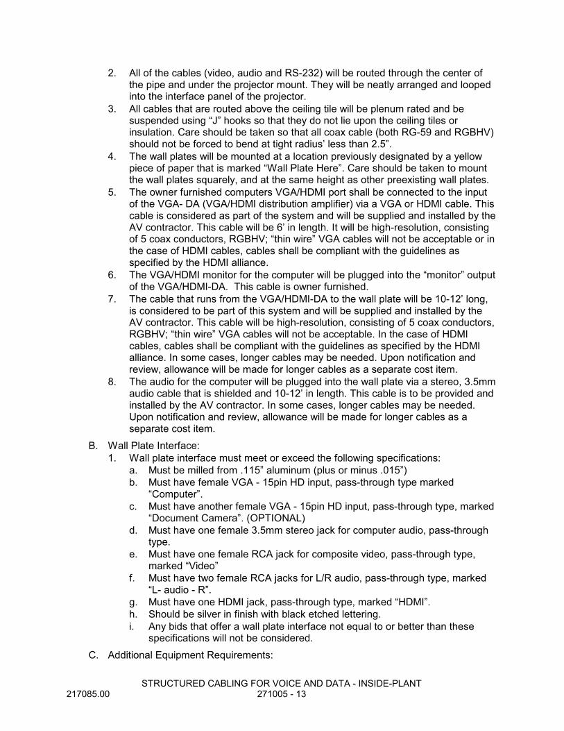
2. All of the cables (video, audio and RS-232) will be routed through the center ofthe pipe and under the projector mount. They will be neatly arranged and loopedinto the interface panel of the projector.
3. All cables that are routed above the ceiling tile will be plenum rated and besuspended using “J” hooks so that they do not lie upon the ceiling tiles orinsulation. Care should be taken so that all coax cable (both RG-59 and RGBHV)should not be forced to bend at tight radius’ less than 2.5”.
4. The wall plates will be mounted at a location previously designated by a yellowpiece of paper that is marked “Wall Plate Here”. Care should be taken to mountthe wall plates squarely, and at the same height as other preexisting wall plates.
5. The owner furnished computers VGA/HDMI port shall be connected to the inputof the VGA- DA (VGA/HDMI distribution amplifier) via a VGA or HDMI cable. Thiscable is considered as part of the system and will be supplied and installed by theAV contractor. This cable will be 6’ in length. It will be high-resolution, consistingof 5 coax conductors, RGBHV; “thin wire” VGA cables will not be acceptable or inthe case of HDMI cables, cables shall be compliant with the guidelines asspecified by the HDMI alliance.
6. The VGA/HDMI monitor for the computer will be plugged into the “monitor” outputof the VGA/HDMI-DA. This cable is owner furnished.
7. The cable that runs from the VGA/HDMI-DA to the wall plate will be 10-12’ long,is considered to be part of this system and will be supplied and installed by theAV contractor. This cable will be high-resolution, consisting of 5 coax conductors,RGBHV; “thin wire” VGA cables will not be acceptable. In the case of HDMIcables, cables shall be compliant with the guidelines as specified by the HDMIalliance. In some cases, longer cables may be needed. Upon notification andreview, allowance will be made for longer cables as a separate cost item.
8. The audio for the computer will be plugged into the wall plate via a stereo, 3.5mmaudio cable that is shielded and 10-12’ in length. This cable is to be provided andinstalled by the AV contractor. In some cases, longer cables may be needed.Upon notification and review, allowance will be made for longer cables as aseparate cost item.
B. Wall Plate Interface:1. Wall plate interface must meet or exceed the following specifications:
a. Must be milled from .115” aluminum (plus or minus .015”)b. Must have female VGA - 15pin HD input, pass-through type marked
“Computer”.c. Must have another female VGA - 15pin HD input, pass-through type, marked
“Document Camera”. (OPTIONAL)d. Must have one female 3.5mm stereo jack for computer audio, pass-through
type.e. Must have one female RCA jack for composite video, pass-through type,
marked “Video”f. Must have two female RCA jacks for L/R audio, pass-through type, marked
“L- audio - R”.g. Must have one HDMI jack, pass-through type, marked “HDMI”.h. Should be silver in finish with black etched lettering.i. Any bids that offer a wall plate interface not equal to or better than these
specifications will not be considered.C. Additional Equipment Requirements:

STRUCTURED CABLING FOR VOICE AND DATA - INSIDE-PLANT217085.00 271005 - 14
1. VGA/HDMI Distribution Amplifier:a. The distribution amplifier must be capable of a bandwidth of >300 MHz, be
able to deliver a clear XGA signal up to 150’. It must also have one input andtwo outputs - one output for the local monitor and one for the projector.
b. Projector Mount:c. The projector mount must securely hold the projector properly in place while
allowing easy access for the changing and cleaning of air filters.d. Projector Mount Pipe:e. The pipe that connects the projector mount to the ceiling plate must be 1.5” in
diameter so that video and audio cables can be neatly routed through thepipe. Pipe must be 8-12” long in order to allow for proper ventilation in andaround the projector. Color is black.
f. Video and Audio Cables:g. All cables that are routed above the ceiling must be plenum rated.
1) VGA cables - VGA cables must be 26-25AWG, 5-coax (RGBHV), 75ohm, with overall inner overlapping aluminum shield and outer copperbraided shield with 95% coverage or higher.(a) Composite Video Cables - Composite video cables must be RG-59,
75 ohm, coax type with a 20AWG center conductor. Outer shieldmust be braided copper with 95% coverage or better.
(b) HDMI Cables - HDMI cable should have an inline booster that doesnot require an external power supply.
(c) RCA Audio Cables - RCA audio cables must have four - 18 to 22AWG conductors with an outer shield plus a drain wire. Drain wiremust be grounded at one end only.
2. 3.5mm Audio Cables - 3.5mm audio cables must have three - 18 to 22 AWGconductors with an outer shield plus a drain wire. Drain wire must be grounded atone end only.
D. Cables & Equipment1. 3074946 C2G DOUBLE GANG HDMI/3RCA/3.5/VGA WP
Mfg#: 397042. 1765638 C2G 15FT PLEN 3.5MM STEREO M/M CBL
Mfg#: 405153. 2240723 C2G 35FT PRO SERIES PLENUM HDMI CBL
Mfg#: 411924. 2240738 C2G 50FT PRO SERIES PLENUM HDMI CBL
Mfg#: 411935. 3768009 C2G 75FT HI-SPD HDMI AOC PLEN CMP
Mfg#: 413726. 2435807 C2G 35FT PLENUM HD15 M/M SXGA CABLE
Mfg#: 400937. 2243723 C2G 50FT PLENUM ROUNDED HD15 M/M SXG
Mfg#: 400948. 2500135 C2G 75FT PLENUM ROUNDED HD15 M/M CAB
Mfg#: 400959. 1811894 C2G 35FT PLN COMPOSITE W/AUDIO CBL
Mfg#: 4052510. 1862297 C2G 50FT PLENUM A/V M/M CABLE
Mfg#: 40526

STRUCTURED CABLING FOR VOICE AND DATA - INSIDE-PLANT217085.00 271005 - 15
11. 2575723 C2G 75FT PLENUM A/V M/M CABLEMfg#: 40527
12. 2170746 C2G 25FT PLENUM 3.5MM STEREO M/M CABMfg#: 40516
13. 1766689 C2G 50FT LP PLN 3.5MM CAB M/MMfg#: 40518
14. 3970523 OWI 2 SOURCE AMPLIFIED 6.5 SPEAKMfg#: 2X2AMP-R2S62
15. 3538416 Epson PowerLite 675W SHORT THROWMfg#: V11H745520
16. 3540298 EPSON MOUNT F/PL AND BL 520/530 SRMfg#: V12H706020
17. 3605210 EPSON PL 99WH PROJECTOR WXGA 3000 LUMfg#: V11H686020
18. 1442395 EPSON UNIV PROJECTOR CEILING MOUNTMfg#: ELPMBPJF
2.09 ENCLOSURESA. Size: As indicated on drawings.B. Do not paint over UL label.C. Manufacturers: Subject to compliance with requirements, provide products by one of
the following manufacturers:1. Cooper B-Line, Inc.2. Chatsworth Products, Inc.3. Homaco, Inc, an Ortronics/LeGrand company4. Hubbell Inc., Hubbell Premise Wiring5. Southwest Data Products
D. Racks and Cabinets: All shall be keyed alikeE. Open bay or enclosed: 4 post racks.
1. Racks (Open bay): EIA-310-D standard 19 inch wide component racks.a. All data/network cabinets shall be open bay relay racks designed in
accordance with EIA RS-310c STANDARDS (19"). The racks shall beconstructed of aluminum with durable black polyurethane or mill finishdesigned for 19" rack mount equipment. Racks shall be 84" high.1) 16 gage steel construction with corrosion resistant finish; vertical and
horizontal cable management channels, top and bottom cable troughs,and grounding lug.
2) Vertical U-channel3) 6.5" channel depth (unless specified on drawing as 14" channel depth)4) EIA hole pattern front and rear.5) Vertical cable management rings6) Floor and ceiling cable access for routing and management of
distribution cables.7) Cable support bracket kit for ladder rack.8) Ladder rack shall be securely attached to top of cabinets and wall to
provide cable raceway path and structural support.9) All MDF racks shall be secured to floor through approved anchors.10) Slotted ducts for cable management
STRUCTURED CABLING FOR VOICE AND DATA - INSIDE-PLANT217085.00 271005 - 16
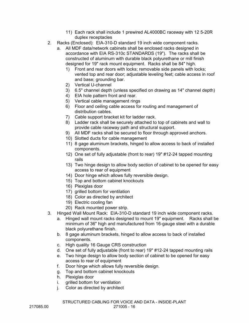
11) Each rack shall include 1 prewired AL4000BC raceway with 12 5-20Rduplex receptacles
2. Racks (Enclosed): EIA-310-D standard 19 inch wide component racks.a. All MDF data/network cabinets shall be enclosed racks designed in
accordance with EIA RS-310c STANDARDS (19"). The racks shall beconstructed of aluminum with durable black polyurethane or mill finishdesigned for 19" rack mount equipment. Racks shall be 84" high.1) Front and rear doors with locks; removable side panels with locks;
vented top and rear door; adjustable leveling feet; cable access in roofand base; grounding bar.
2) Vertical U-channel3) 6.5" channel depth (unless specified on drawing as 14" channel depth)4) EIA hole pattern front and rear.5) Vertical cable management rings6) Floor and ceiling cable access for routing and management of
distribution cables.7) Cable support bracket kit for ladder rack.8) Ladder rack shall be securely attached to top of cabinets and wall to
provide cable raceway path and structural support.9) All MDF racks shall be secured to floor through approved anchors.10) Slotted ducts for cable management11) 8 gage aluminum brackets, hinged to allow access to back of installed
components.12) One set of fully adjustable (front to rear) 19" #12-24 tapped mounting
rails13) Two hinge design to allow body section of cabinet to be opened for easy
access to rear of equipment14) Door hinge which allows fully reversible design.15) Top and bottom cabinet knockouts16) Plexiglas door17) grilled bottom for ventilation18) Color as directed by architect19) Electric cooling fan20) Rack mounted power strip.
3. Hinged Wall Mount Rack: EIA-310-D standard 19 inch wide component racks.a. Hinged wall mount racks designed to mount 19" equipment. Racks shall be
minimum of 36" high and manufactured from 16-gauge steel with a durableblack polyurethane finish.
b. 8 gage aluminum brackets, hinged to allow access to back of installedcomponents.
c. High quality 16 Gauge CRS constructiond. One set of fully adjustable (front to rear) 19" #12-24 tapped mounting railse. Two hinge design to allow body section of cabinet to be opened for easy
access to rear of equipmentf. Door hinge which allows fully reversible design.g. Top and bottom cabinet knockoutsh. Plexiglas doori. grilled bottom for ventilationj. Color as directed by architect

STRUCTURED CABLING FOR VOICE AND DATA - INSIDE-PLANT217085.00 271005 - 17
k. Electric cooling fanl. Rack mounted power strip.
4. WIRE MANAGEMENT PANELSa. Manufacturers: Subject to compliance with requirements, provide products
by one of the following manufacturers:1) Cooper B-Line, Inc.2) Chatsworth Products, Inc.3) Homaco, Inc, an Ortronics/LeGrand company4) Hubbell Premise Wiring, Hubbell Inc.5) Southwest Data Products
b. Vertical wire management panels: Double-sided, steel or aluminum, verticalpanels mounted to side of communications floor-mounted racks, providing forfront and rear management of horizontal and backbone cable in-feeds andequipment patch cords.1) Panels must be “open-ring” style, consisting of a series of metal rings
without overall covers, utilizing lockable latches or integral fingers toretain cables on both front and rear of panel. Plastic “routing” rings or“covered-slotted duct” management panel styles are not permitted.
2) Dimensions: 45 rack-units high x minimum 6”-width x minimum12”-overall depth
3) Maximum 12” spacing between latches or fingers.4) Panel to feature front/rear pass through ports every 24” minimum.5) Panels to feature rolled edges or edge guards to protect cables.6) Finish: Clear mill or powder-coat, black.7) A vertical management section shall be provided for each individual rack.
Coordinate quantity with Contract Drawings, and location of electricalsurface raceway for power receptacles. If more than one rack is installedin a row, a single vertical management section may be used to adjointwo racks.
c. Horizontal wire management panels: Double-sided, steel or aluminum,horizontal channels mounted to vertical rails of communicationsfloor-mounted racks or concentrator enclosures, providing for front and rearmanagement of horizontal cable in-feeds and equipment patch cords.1) Panels must be “open-ring” style, consisting of a series of metal rings,
without an overall cover. Plastic “routing” rings or “covered-slotted duct”management panel styles are not permitted.
2) Panel must have a minimum of four (4) rings across front and rear.Rings shall be minimum 3”-deep.(a) COORDINATE WIRE MANAGEMENT SIZES AND POSITIONS IN
CONTRACT DRAWINGS.3) Height: [1] [2] or [4] rack units high as indicated in Contract Drawings.4) Provide horizontal wire management panels above and below all
horizontal cable patch panels and other termination housings.5) Provide horizontal wire management panels above and below open rack
units dedicated to future network electronics, as indicated in ContractDrawings.
6) Finish: Black5. ELECTROSTATIC DISCHARGE PORT KIT

STRUCTURED CABLING FOR VOICE AND DATA - INSIDE-PLANT217085.00 271005 - 18
a. Manufacturer: Subject to compliance with requirements, provide products bythe following manufacturer:1) Panduit Corporation, part no. RGESD-1
b. Kit: One-hole barrel lug, angled at 45-degrees, permanently marked withprotective earth (ground) symbol, designed to accommodate a 4mm ESDwrist strap plug. Kit shall include an antioxidant compound, and one #12-24 x½” thread-forming screw.1) Wall Mounted Racks: 8 gage aluminum brackets, hinged to allow
access to back of installed components.2) Floor Mounted Racks: 16 gage steel construction with corrosion
resistant finish; vertical and horizontal cable management channels, topand bottom cable troughs, and grounding lug.
3) Freestanding Cabinets: Front and rear doors with locks; removable sidepanels with locks; vented top and rear door; adjustable leveling feet;cable access in roof and base; grounding bar.
c. Outlet Boxes: For flush mounting in walls; depth as required toaccommodate cable manufacturer's recommended minimum conductor bendradius.1) Size, Unless Otherwise Indicated: 4 inches square by 2-1/8 inches
deep.2) Wall-Mounted Telephones: 4 inches high by 2 inches wide by 2-1/8
inches deep.
2.10 LADDER RACK RUNWAYA. Manufacturers: Subject to compliance with requirements, provide products by one of
the following manufacturers:1. Cooper B-Line, Inc.2. Chatsworth Products, Inc.3. Southwest Data Products
B. Materials: Steel, suitable for indoors and protected against corrosion by power-coatpaint finish.1. Finish Color: Gray2. Feature rounded edges and smooth surfaces.
C. Sizes and Configurations: Nominally 12 inches wide, and a rung spacing of 6 to 12inches on center, unless otherwise indicated in Contract Drawings. Standard Length:9'-11-1/2”.
D. Rungs and Rails: Nominally 1” x 1/2" or 3/8” tubular steel rungs, featuring roundededges, welded to 1-1/2” or 2” longitudinal rails (stringers).
E. Packaging: Individually boxed to prevent scratches and damage.2.11 LADDER RACK RUNWAY ACCESSORIES
A. Manufacturers: Subject to compliance with requirements, provide products by one ofthe following manufacturers:1. Cooper B-Line, Inc.2. Chatsworth Products, Inc.3. Southwest Data Products
B. Finish:1. Powder coat paint, gray
STRUCTURED CABLING FOR VOICE AND DATA - INSIDE-PLANT217085.00 271005 - 19
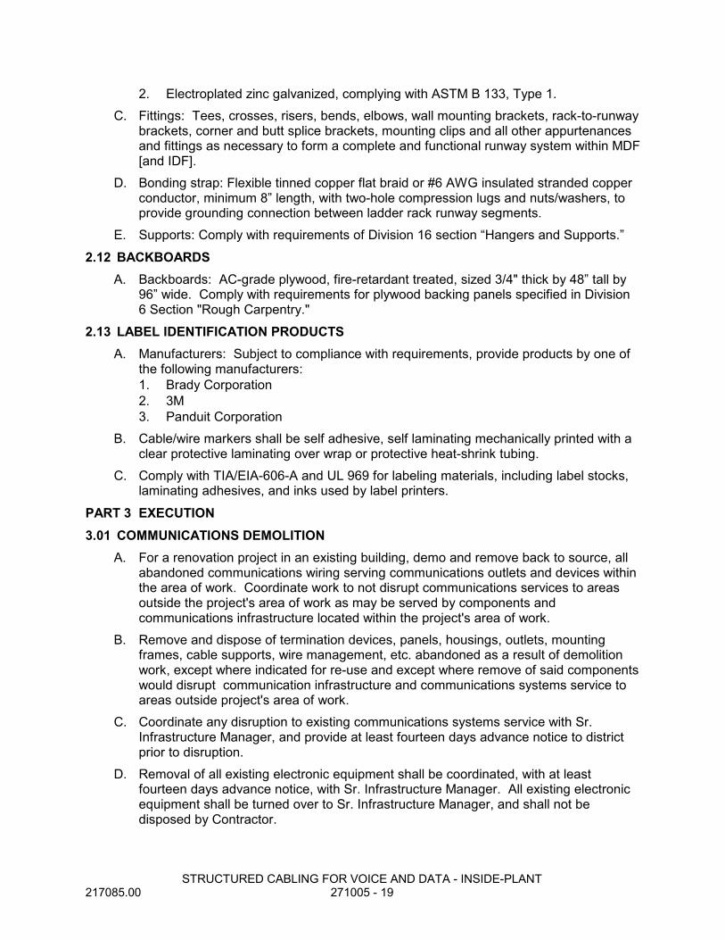
2. Electroplated zinc galvanized, complying with ASTM B 133, Type 1.C. Fittings: Tees, crosses, risers, bends, elbows, wall mounting brackets, rack-to-runway
brackets, corner and butt splice brackets, mounting clips and all other appurtenancesand fittings as necessary to form a complete and functional runway system within MDF[and IDF].
D. Bonding strap: Flexible tinned copper flat braid or #6 AWG insulated stranded copperconductor, minimum 8” length, with two-hole compression lugs and nuts/washers, toprovide grounding connection between ladder rack runway segments.
E. Supports: Comply with requirements of Division 16 section “Hangers and Supports.”
2.12 BACKBOARDSA. Backboards: AC-grade plywood, fire-retardant treated, sized 3/4" thick by 48” tall by
96” wide. Comply with requirements for plywood backing panels specified in Division6 Section "Rough Carpentry."
2.13 LABEL IDENTIFICATION PRODUCTSA. Manufacturers: Subject to compliance with requirements, provide products by one of
the following manufacturers:1. Brady Corporation2. 3M3. Panduit Corporation
B. Cable/wire markers shall be self adhesive, self laminating mechanically printed with aclear protective laminating over wrap or protective heat-shrink tubing.
C. Comply with TIA/EIA-606-A and UL 969 for labeling materials, including label stocks,laminating adhesives, and inks used by label printers.
PART 3 EXECUTION3.01 COMMUNICATIONS DEMOLITION
A. For a renovation project in an existing building, demo and remove back to source, allabandoned communications wiring serving communications outlets and devices withinthe area of work. Coordinate work to not disrupt communications services to areasoutside the project's area of work as may be served by components andcommunications infrastructure located within the project's area of work.
B. Remove and dispose of termination devices, panels, housings, outlets, mountingframes, cable supports, wire management, etc. abandoned as a result of demolitionwork, except where indicated for re-use and except where remove of said componentswould disrupt communication infrastructure and communications systems service toareas outside project's area of work.
C. Coordinate any disruption to existing communications systems service with Sr.Infrastructure Manager, and provide at least fourteen days advance notice to districtprior to disruption.
D. Removal of all existing electronic equipment shall be coordinated, with at leastfourteen days advance notice, with Sr. Infrastructure Manager. All existing electronicequipment shall be turned over to Sr. Infrastructure Manager, and shall not bedisposed by Contractor.

STRUCTURED CABLING FOR VOICE AND DATA - INSIDE-PLANT217085.00 271005 - 20
3.02 DELIVERY AND STORAGEA. Receive, handle, and store communications system items and materials at the project
site. Materials and items shall be placed so that they are protected from damage anddeterioration.
B. Stage materials in a secure area of the project site until installation.
3.03 INSTALLATION - GENERALA. The drawings for work under telecommunications specification sections related to
communication systems are diagrammatic and are intended to convey the scope ofwork and indicate the general arrangement of outlets, equipment, terminationhardware, fixtures and other work included in the Contract.
B. Location of items required by the drawings or specifications not definitely fixed bydimensions are approximate only and exact locations necessary to secure the bestconditions and results shall be determined at the site and shall be subject to theapproval of the Owner.
C. Follow drawings in laying out work, check drawings of other trades to verify spaces inwhich work will be installed, and maintain maximum headroom and space conditionsat all points.1. Where headroom or space conditions appear inadequate, the Owner shall be
notified before proceeding with installation.2. Minor rerouting and changes in location shall be made at no additional cost to the
Owner.3. Coordinate the mounting heights of communications equipment and raceways to
clear the opening heights of doors and the heights of equipment which needs tobe removed and replaced.
4. As necessary, adjust elevations of rack-mounted termination hardware andhorizontal wire management panels so as to compensate for rack unit sizes ofactual hardware used, as compared to hardware rack unit sizes depicted inContract Drawings.
D. Perform all work with skilled mechanics of the particular trade involved in a neat andworkmanlike manner.
E. Perform all work in cooperation and coordination with other trades and schedule.F. Furnish other trades advance information on locations and sizes of frames, boxes,
sleeves and openings needed for the work, routes for conduit, and also furnishinformation and shop drawings necessary to permit trades affected to install their workproperly and without delay.
G. Where there is evidence that work of one trade will interfere with the work of othertrades, all trades shall assist in working out space allocations to make satisfactoryadjustments and shall be prepared to submit and revise coordinated shop drawings.
H. With the approval of the Owner and without additional cost to the Owner, make minormodifications in the work as required by structural interferences, by interferences withwork of other trades or for proper execution of the work.
I. Work installed before coordinating with other trades so as to cause interference withthe work of such other trades shall be changed to correct such condition withoutadditional cost to the Owner and as directed by the Owner.
STRUCTURED CABLING FOR VOICE AND DATA - INSIDE-PLANT217085.00 271005 - 21
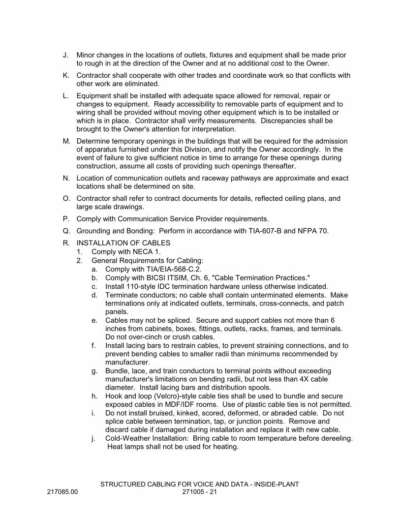
J. Minor changes in the locations of outlets, fixtures and equipment shall be made priorto rough in at the direction of the Owner and at no additional cost to the Owner.
K. Contractor shall cooperate with other trades and coordinate work so that conflicts withother work are eliminated.
L. Equipment shall be installed with adequate space allowed for removal, repair orchanges to equipment. Ready accessibility to removable parts of equipment and towiring shall be provided without moving other equipment which is to be installed orwhich is in place. Contractor shall verify measurements. Discrepancies shall bebrought to the Owner's attention for interpretation.
M. Determine temporary openings in the buildings that will be required for the admissionof apparatus furnished under this Division, and notify the Owner accordingly. In theevent of failure to give sufficient notice in time to arrange for these openings duringconstruction, assume all costs of providing such openings thereafter.
N. Location of communication outlets and raceway pathways are approximate and exactlocations shall be determined on site.
O. Contractor shall refer to contract documents for details, reflected ceiling plans, andlarge scale drawings.
P. Comply with Communication Service Provider requirements.Q. Grounding and Bonding: Perform in accordance with TIA-607-B and NFPA 70.R. INSTALLATION OF CABLES
1. Comply with NECA 1.2. General Requirements for Cabling:
a. Comply with TIA/EIA-568-C.2.b. Comply with BICSI ITSIM, Ch. 6, "Cable Termination Practices."c. Install 110-style IDC termination hardware unless otherwise indicated.d. Terminate conductors; no cable shall contain unterminated elements. Make
terminations only at indicated outlets, terminals, cross-connects, and patchpanels.
e. Cables may not be spliced. Secure and support cables not more than 6inches from cabinets, boxes, fittings, outlets, racks, frames, and terminals.Do not over-cinch or crush cables.
f. Install lacing bars to restrain cables, to prevent straining connections, and toprevent bending cables to smaller radii than minimums recommended bymanufacturer.
g. Bundle, lace, and train conductors to terminal points without exceedingmanufacturer's limitations on bending radii, but not less than 4X cablediameter. Install lacing bars and distribution spools.
h. Hook and loop (Velcro)-style cable ties shall be used to bundle and secureexposed cables in MDF/IDF rooms. Use of plastic cable ties is not permitted.
i. Do not install bruised, kinked, scored, deformed, or abraded cable. Do notsplice cable between termination, tap, or junction points. Remove anddiscard cable if damaged during installation and replace it with new cable.
j. Cold-Weather Installation: Bring cable to room temperature before dereeling. Heat lamps shall not be used for heating.

STRUCTURED CABLING FOR VOICE AND DATA - INSIDE-PLANT217085.00 271005 - 22
k. Pulling Cable: Comply with BICSI ITSIM, Ch. 4, "Pulling Cable." Monitorcable pull tensions, and do not exceed manufacturer's recommended cablepull tension.1) When installing in conduit, use only lubricant approved by cable
manufacturer and do not chafe or damage outer jacket.l. Service Loops: Provide the following minimum extra length of cable, dressed
and routed neatly:1) At MDF/IDF frames: 60 inches, neatly installed in vertical wire manager
or accommodated by additional routing around overhead ladder rackrunway.
2) At Surface Raceway Outlets - Copper: 12 inches, neatly installed insurface raceway channel.
3. UTP Cable Installation:a. Comply with TIA/EIA-568-C.2.b. Maintain pair twists as close as possible to point of termination, but do not
untwist UTP cables more than 1/8 (.125) inch from the point of termination tomaintain cable geometry.
c. Concentrator Enclosures: No cabling is to be routed down through the centerarea of the enclosure so as to inhibit the installation of network electronics.
d. MDF/IDF: Install and route cabling on overhead ladder rack runway andwithin horizontal and vertical cable guides to terminating hardware.
4. Group connecting hardware for cables into separate logical fields.5. Optical Fiber Cable Installation:
a. Comply with TIA/EIA-568-C.3.b. Cables shall terminate with LC-type connectors secured in connecting
hardware that is rack or enclosure mounted.c. Concentrator Enclosures: No cabling is to be routed down through the center
area of the enclosure so as to inhibit the installation of network electronics.d. MDF/IDF: Install and route cabling on overhead ladder rack runway and
within horizontal and vertical cable guides to terminating hardware.6. Separation from EMI Sources:
a. Comply with BICSI TDMM and TIA/EIA-569-A for separating unshieldedcopper voice and data communication cable from potential EMI sources,including electrical power lines and equipment.
b. Separation between open communications cables or cables in nonmetallicraceways and unshielded power conductors and electrical equipment shall beas follows:1) Electrical Equipment Rating Less Than 2 kVA: A minimum of 5 inches.2) Electrical Equipment Rating between 2 and 5 kVA: A minimum of 12
inches.3) Electrical Equipment Rating More Than 5 kVA: A minimum of 24 inches.
c. Separation between communications cables in grounded metallic racewaysand unshielded power lines or electrical equipment shall be as follows:1) Electrical Equipment Rating Less Than 2 kVA: A minimum of 2-1/2
inches.2) Electrical Equipment Rating between 2 and 5 kVA: A minimum of 6
inches.3) Electrical Equipment Rating More Than 5 kVA: A minimum of 12 inches.

STRUCTURED CABLING FOR VOICE AND DATA - INSIDE-PLANT217085.00 271005 - 23
d. Separation between communications cables in grounded metallic racewaysand power lines and electrical equipment located in grounded metallicconduits or enclosures shall be as follows:1) Electrical Equipment Rating Less Than 2 kVA: No requirement.2) Electrical Equipment Rating between 2 and 5 kVA: A minimum of 3
inches.3) Electrical Equipment Rating More Than 5 kVA: A minimum of 6 inches.
e. Separation between Communications Cables and Electrical Motors andTransformers, 5 kVA or HP and Larger: A minimum of 48 inches.
f. Separation between Communications Cables and Fluorescent Fixtures: Aminimum of 5 inches.
S. INSTALLATION OF CABINET RACKS AND ENCLOSURES1. Comply with NECA 1.2. Install all communications hardware components in accordance with project
specifications and plan, elevation, and layout information within ContractDrawings.
3. The contractor shall coordinate the installation of communications cabinets, racksand enclosures with the installation of the communications pathways and cablingto eliminate any potential damage to cables, or any other installedcommunications components or equipment.
4. Ladder Rack: Comply with NEMA VE 2 and TIA/EIA-569-A-7.a. Support overhead ladder rack at minimum 5 foot intervals. Where ladder rack
meets wall, provide a wall mount bracket to secure. Provide supports at eachconnection or intersection point. Mount at elevation and layout in accordancewith Contract Drawings.
b. Ladder rack shall not penetrate any fire-rated walls or floors.c. Provide minimum 1-foot clearance above ladder rack, and sufficient work
space around the ladder rack, to access the ladder rack to permit the additionor removal of cable without removing any section of ladder rack or installedsupports.
d. Ladder rack system shall not be installed in manner that obstructs access toany new or existing equipment, or to infringe on any Code-requiredclearances.
e. Do not fasten ladder rack to pipes, ducts, mechanical equipment, or electricalconduit.
5. Backboards: Install plywood with “A” side outward and at elevation and walllocation(s) as indicated in Contract Drawings. Butt adjacent sheets tightly, andform smooth gap-free corners. Cover fire-rating mark during painting. Removecover afterwards, leaving mark exposed for subsequent inspection by authorityhaving jurisdiction.
6. Communications Floor-mounted Racks: Assemble and install in accordance withmanufacturer's instructions and recommendations. Racks shall be assembledsuch that mounting rails are exactly perpendicular to the base.a. Secure to floor utilizing lag bolts or masonry anchors, and washers,
appropriate to application and flooring condition. The use of a Tapcon, orequal, masonry screw with washer is not acceptable. Secure at all fourlocations of rack base.
b. Secure each communications floor-mounted rack to overhead ladder rackusing eack-to-runway mounting plates, brackets, j-bolts, nuts/washers, etc.,
STRUCTURED CABLING FOR VOICE AND DATA - INSIDE-PLANT217085.00 271005 - 24
installed in compliance with manufacturer's instructions andrecommendations.
7. Wire management panels: Secure to communication relay racks in accordancewith manufacturer's instructions.
3.04 PATHWAY EXAMINATIONA. Examine pathway elements intended for cables.
1. Verify proposed routes of pathways. Check raceways, ladder racks, and otherelements for compliance with space allocations, clearances, installationtolerances, hazards to cable installation, and other conditions affectinginstallation. Verify that cabling can be installed complying with EMI clearancerequirements.
2. Prepare wall penetrations and verify that penetrations of rated fire walls are madeusing products labeled for type of wall penetrated.
3. Identify plan to support cables and raceways in suspended ceilings. Verify weightof individual types and sizes of cables. Verify that load capacity of cable supportstructures is adequate for each pathway.
4. Proceed with installation only after unsatisfactory conditions have been corrected.
3.05 INSTALLATION OF PATHWAYSA. Underground Service Entrance: Install conduit at least 18 inches below finish grade;
encase in at least 3 inches thick concrete for at least 60 inches out from the buildingline.
B. Install pathways with the following minimum clearances:1. 48 inches from motors, generators, frequency converters, transformers, x-ray
equipment, and uninterruptible power systems.2. 12 inches from power conduits and cables and panelboards.3. 5 inches from fluorescent and high frequency lighting fixtures.4. 6 inches from flues, hot water pipes, and steam pipes.
C. Conduit, in Addition to Requirements of Section 260533.13:D. Conduit:
1. Do not install more than 2 (two) 90 degree bends in a single horizontal cable run.2. Leave pull cords in place where cables are not initially installed.3. Conceal conduit under floor slabs and within finished walls, ceilings, and floors
except where specifically indicated to be exposed.a. Conduit may remain exposed to view in mechanical rooms, electrical rooms,
and telecommunications rooms.b. Treat conduit in crawl spaces and under floor slabs as if exposed to view.c. Where exposed to view, install parallel with or at right angles to ceilings,
walls, and structural members.d. Under floor slabs, locate conduit at 12 inches, minimum, below vapor
retarder; seal penetrations of vapor retarder around conduit.E. Cable Routing
1. All cabling to re routed within approved raceway or above lay-in ceiling. Cablingshall be hidden by ceiling or raceway in all locations of the building with theexception of IDF and MDF rooms or as otherwise noted on the drawings.a. Where cable tray is provided, route cabling within cable tray.b. Where conduit sleeve is provided, route cabling within conduit sleeve
STRUCTURED CABLING FOR VOICE AND DATA - INSIDE-PLANT217085.00 271005 - 25
c. Above lay-in ceilings, where cable tray or conduit sleeves are not available:1) Where raceway for cabling is not provided, Contractor shall run cabling
through Erico Cablecat 2" J hooks.(a) J hooks shall be directly attached to building structure at a maximum
of 4'-0" center-to-center.(b) Additional J hooks will be added as necessary to limit the maximum
cable catenary (cable sag) to 12" maximum.(c) Install tye-wraps around all J hooks upon completion of cable pulls.(d) J hook cable density shall not exceed 60% of the maximum cable
count suggested by manufacture. If necessary, provide additionallevel of J hooks for high cable density runs.
(e) Contractor shall provide all mounting hardware (threaded rod,unistrut, etc.) Necessary to solidly mounted, complete cableraceway system.
3.06 FIRESTOPPINGA. Utilize an approved firestop assembly to seal all cable and raceway penetrations of
fire-rated floor and wall assemblies. Assembly must achieve the samesmoke/fire-resistance rating as the floor or wall being penetrated.
B. Comply with requirements in Division 7 Section "Through-Penetration FirestopSystems."
C. Comply with TIA/EIA-569-A, Annex A, "Firestopping."D. Comply with BICSI TDMM, "Firestopping Systems" Article.
3.07 GROUNDINGA. Install grounding according to BICSI TDMM, "Grounding, Bonding, and Electrical
Protection" Chapter.B. Comply with ANSI-J-STD-607-A.C. Coordinate location of communications grounding bus bar to minimize the length of
bonding conductors.D. Bond metallic equipment to the communications grounding bus bar, using not smaller
than No. 6 AWG equipment grounding conductor.E. Bond each segment of ladder rack runway using bonding straps. Ladder rack
connection fittings are not considered an acceptable bonding mechanism. Installbonding straps in accordance with manufacturer's instructions and recommendations.
F. Bond metallic equipment to the communications grounding bus bar in MDF [or IDF],using not smaller than No. 6 AWG equipment grounding conductor.1. Ground ladder rack system to communications grounding bus bar.2. Ground each floor-mounted rack to communications grounding bus bar. Bonding
to overhead ladder rack is not a permissible.3. Ground each concentrator enclosure to communications grounding bus bar. At
enclosure, terminate equipment grounding conductor to grounding bus barlocated within enclosure.
G. ESD Port Kit: Install ESD port kit in accordance with manufacturer's instructions andrecommendations, on communications mounting elements as follows:
STRUCTURED CABLING FOR VOICE AND DATA - INSIDE-PLANT217085.00 271005 - 26
1. Floor-mounted racks: Mount a kit directly to both the front and the rear sides ofthe right vertical mounting rail of the center most rack in MDF [and the centermost rack in IDF], at 48” above floor, using thread-forming screw and antioxidantcompound. Coordinate exact location with Owner.
3.08 IDENTIFICATIONA. All labeing standards will be determined in conjuction with the district information
technology administrator. The district technology administrator shall have finalapproval on all labeling schemes. Labeling schemes applied without approval shall bereplaced/modified to comply.
B. Labeling shall minimually comply with EIA/TIA labeling standards.C. LABELING HIERARCHY
1. When labeling communications cabling and pathways always begin the labelingscheme with the room or location of greater significance.
2. Consult with district Sr. Infrastructure Manager for clarifications regardingapplication of hierarchy table to the project. Hierarchy relationships that must beadhered to include, but are not limited to:a. Cabling and/or pathways between the MDF and any IDFs must list the MDF
first.b. Cabling and/or pathways between a concentrator enclosure and the work
area must list the concentrator enclosures first.c. Cabling and/or pathways between an MDF or IDF and a wireless access
point outlet must list the MDF or IDF first.3. Labeling must be the same on both ends of the cable and/or pathway.4. Labeling for all communications infrastructure elements shall be consistent across
the installation. Coordinate with requirements for labels and identification definedin Contract Drawings.
D. WIRE IDENTIFICATION1. Cable/wire markers shall be installed within four (4) inches of each end of the
cable, and where cable is accessible in junction or pull boxes. Information list oncable/wire marker shall include, but is not limited to:a. Cable and typeb. Termination hardwarec. Termination position
2. Identification within Connector Fields in MDF, [IDFs,] and concentratorenclosures: Label each connector and each discrete unit of cable-terminatingand connecting hardware.
E. WORKSTATION LABELING1. Administration at the work area / workstation will be carried out in proximity to the
closest Distribution Frame (MDF, IDF).2. The administration of the individual Data/Voice locations will reference the MDF
or ID room location.3. Administration of the individual jack locations will be used for local tracking or
tracing of the patch panel termination points (Data/Voice jacks back to the closesttermination in the Distribution Frame). Typical numbering of the jack locations willbegin with the termination point closest to the Distribution Frame and continuingin numerical series outward from that location.

STRUCTURED CABLING FOR VOICE AND DATA - INSIDE-PLANT217085.00 271005 - 27
3.09 CUTTING AND PATCHINGA. Cut, channel, chase, and drill floors, walls, partitions, ceilings, and other surfaces
required to permit communications systems installation, including all pathwayelements and supports necessary for same. Perform cutting by skilled mechanics oftrades involved. Perform work so as to not impair structural stability of buildingconstruction and systems.
B. Conduits passing through roofs or other surfaces exposed to weather shall be properlyflashed as specified in roofing and waterproofing sections. This flashing work shall bepart of this division of work.
C. Repair and refinish disturbed finish materials and other surfaces to match adjacentundisturbed surfaces. Install new firestopping where existing firestopping has beendisturbed during the course of install. Repair and refinish materials and other surfacesby skilled mechanics of trades involved.
3.10 REFINISHING AND TOUCHUP PAINTINGA. Refinish and touch up paint. Paint materials and application requirements are
specified in Section "Painting."1. Clean damaged and disturbed areas and apply primer, intermediate, and finish
coats to suit the degree of damage at each location.2. Follow paint manufacturer's written instructions for surface preparation and for
timing and application of successive coats.3. Repair damage to galvanized finishes with zinc-rich paint recommended by
manufacturer.4. Repair damage to PVC or paint finishes with matching touchup coating
recommended by manufacturer.3.11 CLEANING
A. On completion of installation inspect exposed finishes. Remove burrs, dirt, paintspots, and construction debris. Repair damaged finish(es), including chips, scratches,and abrasions.
B. All equipment, hardware and finishes shall be cleaned prior to final acceptance.Unless otherwise indicated, clean shall mean free of dust, dirt, mud, debris, oil,grease, residues, and contamination.
C. Protect equipment and installations and maintain conditions to ensure that coatings,finishes, and cabinets are without damage or deterioration at time of SubstantialCompletion. Protect conduit and wireway openings against the entrance of foreignmatter by means of plugs or caps. Cover fixtures, materials, equipment and devicesfurnished or installed under this section or otherwise protect against damage, bothbefore and after installation. Hardware, materials, equipment, or devices damagedprior to final acceptance of the work shall be restored to their original condition orreplaced.
D. During the course of communications installation work, provide for on-going properdisposal of all debris, including but not limited to: equipment packaging and shippingmaterials, shipping pallets, empty cable reels/boxes, cable cuttings, etc. TheContractor shall, at all times, keep the site free from accumulations of waste materialor rubbish caused by its employees or work. Remove all crates, cartons, and otherwaste materials or trash from the working areas at the end of each working day.
STRUCTURED CABLING FOR VOICE AND DATA - INSIDE-PLANT217085.00 271005 - 28
Flammable waste material must be removed from the working areas at the time ofgeneration. All rubbish and debris, combustible or not, shall be discarded in coveredmetal containers daily and removed from the premises at least weekly and legallydisposed of.
3.12 COMMISSIONING AND DEMONSTRATIONA. INSPECTION
1. Visually inspect UTP and optical fiber cable jacket materials for NRTL certificationmarkings. Inspect cabling terminations in communications equipment rooms forcompliance with color-coding for pin assignments, and inspect cablingconnections for compliance with TIA/EIA-568-B.1.
2. Visually confirm Category 6 marking of outlets, outlet/connectors, and patchpanels for horizontal UTP cabling for Data/Wireless, Kronos and MMTVapplications.
3. Visually confirm Category 5e marking of outlets, outlet/connectors, terminationblocks and patch panels for horizontal UTP cabling voice and 25-pair Category 5ebackbone applications.
4. Visually confirm Category 3 marking of copper backbone UTP cables for indoorvoice backbone applications.
5. Visually inspect cable placement, cable termination, grounding and bonding,equipment and patch cords, and labeling of all components.
6. Inspect cable terminations for color coded labels of proper type.B. FIELD QUALITY CONTROL
1. Perform tests and inspections.2. Copper UTP Cable Tests:
a. Copper UTP Test Instruments:1) Test instruments shall meet or exceed applicable requirements in
TIA/EIA-568-B.2. Perform tests with a tester that complies withperformance requirements in "Test Instruments (Normative)" Annex,complying with measurement accuracy specified in "MeasurementAccuracy (Informative)" Annex. Use only test cords and adapters thatare qualified by test equipment manufacturer for permanent link testconfiguration.
2) For horizontal UTP cable certification tests, use a Level III tester.b. Copper Backbone UTP Cable Tests:
1) Test copper backbone UTP cabling for DC loop resistance, shorts,opens, intermittent faults, polarity between conductors, and for insertionloss (attenuation). Test operation of shorting bars in connection blocks. Test cables after termination but not cross-connection.
c. UTP Performance Tests:1) Test permanent link for each outlet. Perform the following tests
according to TIA/EIA-568-B.1 and TIA/EIA-568-B.2:(a) Wire map.(b) Length (physical vs. electrical, and length requirements).(c) Insertion loss.(d) Near-end crosstalk (NEXT) loss.(e) Power sum near-end crosstalk (PSNEXT) loss.(f) Equal-level far-end crosstalk (ELFEXT).(g) Power sum equal-level far-end crosstalk (PSELFEXT).

STRUCTURED CABLING FOR VOICE AND DATA - INSIDE-PLANT217085.00 271005 - 29
(h) Return loss.(i) Propagation delay.(j) Delay skew.
2) Testing for Category 6 horizontal UTP must additionally report values forattenuation-to-crosstalk ratio (ACR), and power sumattenuation-to-crosstalk ratio (PSACR).
3) A star (“*”) passing shall not be considered acceptable.3. Optical Fiber Cable Tests:
a. Optical Fiber Test Instruments:1) Test instruments shall meet or exceed applicable requirements in
TIA/EIA-568-B.1. Use only test cords and adapters that are qualified bytest equipment manufacturer for channel or link test configuration.
b. Optical Time Domain Reflectometry Tests: After terminating optical fibercables, one individual fiber from each backbone cable installed shall betested using an optical time domain reflectometer (OTDR). Perform OTDRtesting in accordance with manufacturer's recommended test procedures. Test to determine the installed length, continuity, and OTDR-basedattenuation measurement. Provide test report identifying backbone cableidentification and indicating corresponding values from tests.
c. Link End-to-End Attenuation Tests: Perform optical fiber end-to-end linktests according to TIA/EIA-568-B.1 and TIA/EIA-568-B.3.1) Multimode backbone link measurements: Test at 850 or 1300 nm in
both directions according to TIA/EIA-526-14-A, Method B, OneReference Jumper.
2) Attenuation test results shall be less than that calculated according toequation in TIA/EIA-568-B.1.
3) These readings must not be higher than the "Optimal Attenuation Loss(OAL)". The OAL will be calculated using the manufacturer's factorycertified test results, (db/km) adjusted for the actual installed lengths(dBs) plus the manufacturer's best published attenuation losses for theconnector on this project and/or splice installed on this project (0.25dBfor Connectors and 0.10dB for splices).
4) Link End-to-End Attenuation Test reports shall include:(a) Cable identification and Strand numbers(b) The OAL value for each link(c) The theoretical maximum attenuation value, per TIA/EIA-568-B.1,
for each link(d) Tested values for attenuation
4. Document data for each measurement. Data for submittals shall be printed in asummary report that is formatted similar to Table 10.1 in BICSI TDMM, ortransferred from the instrument to the computer, saved as text files, and printedand submitted.
5. End-to-end cabling will be considered defective if it does not pass tests andinspections. Correct failures and retest to demonstrate compliance; otherwise,remove and replace with new components and retest to demonstrationcompliance with requirements.
6. Prepare test and inspection reports.
END OF SECTION 271005

STRUCTURED CABLING FOR VOICE AND DATA - INSIDE-PLANT217085.00 271005 - 30
EXTENSION/MODIFICATION OF THE EXISTING INTERCOM/MASTER CLOCK AND DISASTERALERT SYSTEMS216043.00 275124 - 1
SECTION 275124
EXTENSION/MODIFICATION OF THE EXISTING INTERCOM/MASTER CLOCK ANDDISASTER ALERT SYSTEMS
PART 1 GENERAL1.01 SECTION INCLUDES
A. Intercom equipment.B. Intercom cable.C. Master Clock equipment.D. Accessories.
1.02 COORDINATION OF WORKA. Contractor shall furnish and install all conduit/raceway as required for the
intercom/master clock system. This includes all raceway explicitly shown on plans orgenerically required for a complete, functional system.
B. Contractor shall furnish and install all specialty backboxes for devices as required forthe intercom/master clock system. This includes all backboxes explicitly shown onplans or generically required for a complete, functional system.
C. Contractor shall furnish and install all branch circuits required for the intercom/masterclock system as specified. This includes all circuits explicitly shown on plans orgenerically required for a complete, functional system.
1.03 SUBMITTALSA. Submit under provisions as described within the general requirements section.B. Shop Drawings: Include the manufacturer's specification sheets, including all the
component parts, control equipment drawings, and layouts, wiring diagrams andfacility wiring, and conduit drawings.
C. Product Data: For each item of equipment.D. Manufacturer's Installation Instructions.E. Project Record Documents: Accurately record actual locations of devices and wiring.F. Operation Data: Include instructions for routine operation of master and remote
stations.G. Maintenance Data: Include instructions for minor troubleshooting, preventive
maintenance, and cleaning.
1.04 QUALITY ASSURANCEA. Manufacturer Qualifications: Company specializing in manufacturing the type of
products specified in this Section with minimum three years of documentedexperience.
B. Supplier Qualifications: Company authorized by manufacturer and specializing insupplying products specified in this Section with minimum three years documentedexperience.
EXTENSION/MODIFICATION OF THE EXISTING INTERCOM/MASTER CLOCK AND DISASTERALERT SYSTEMS217085.00 275124 - 2
C. Installer Qualifications: Company specializing in installing the products specified inthis Section with minimum three years documented experience.
D. All devices shown on drawings shall be new unless otherwise noted.E. All of the above equipment shall be installed in the conduit systems as indicated on
the plans and hereinafter specified. The manufacturer's distributor shall guarantee theentire system for one year against all defects in material and workmanship.
F. All individual panels, housings, and the entire system shall bear the label ofUnderwriters' Laboratories. Contractor shall provide a complete set of operatinginstructions including circuit diagrams and other information necessary for properinstallation, operation, and service maintenance.
1.05 MAINTENANCE SERVICEA. Furnish service and maintenance of intercom system for one year from Date of
Substantial Completion.1.06 SCOPE OF WORK
A. Provide all the necessary components and equipment (wiring, hardware, conduit,boxes, components, etc.) necessary for the replacing/relocation, extension, andaddition to the existing school intercom system as outlined in these specifications.
B. Furnish and install additions to the School sound and intercommunication and clocksystem as shown on the drawings and as hereinafter specified. All new equipmentshall match form and functionality of existing devices/system and satisfy requirementsas hereinafter described.
C. This Contractor will evaluate the existing system and provide additional componentsand modifications to existing system (i.e. system amplifier, switches, console, etc.)required for complete system operation. This Contractor shall provide all equipmentdirectly specified or indirectly implied which is required for completeintercommunication system operation.
D. Contractor shall furnish all equipment and labor necessary for and incidental to thecomplete installation of the School Communications System as directly described orindirectly implied on the drawings and within this specification.
PART 2 PRODUCTS2.01 INTERCOM/CLOCK SYSTEM
A. Manufacturers:1. Match existing2. Rauland (Interstate Electronics - (630) 789-8700)
2.02 EQUIPMENTA. Rauland
1. Power amplifiers sized and number as required2. Rauland ACC1300 volume controls as required3. Rauland USO188 cone type loudspeakers as required4. Rauland ACC1001 round speaker baffles as required5. Rauland ACC1003 Square speaker baffles as required6. Rauland ACC1101 round loudspeaker backbox assemblies as required7. Rauland ACC1102 square loudspeaker backbox assemblies as required
EXTENSION/MODIFICATION OF THE EXISTING INTERCOM/MASTER CLOCK AND DISASTERALERT SYSTEMS217085.00 275124 - 3
8. Rauland ACC1104 loudspeaker support bridges as required9. West Penn plenum intercom cable as required (2 conductor unshielded)10. West Penn plenum speaker cable as required (2 conductor shielded)
a. Shield shall not be used for intercom cable. Intercom/speaker zone commoncable shall be two conductor shielded and two conductor unshielded (plenumrated)
B. Equipment listed represents the required level or quality. Actual equipment may differ;however, all components must be fully compatible with existing intercommunicationsystem.
C. MASTER CLOCK SYSTEM - Existing Simplex Clock System1. The master control clock shall be complete with operational lithium current time
battery back-up system. The master clock system shall be furnished completewith a rack mounted screened companion instruction panel, detailingprogramming procedures in step-by-step sequence. The master clock systemshall be rack mounted within and be a part of the intercom system controlequipment.
D. SECONDARY CLOCKS1. The analog secondary clocks in clock speaker panels shall be 12" flush/surface
(refer to drawings) -mounted Rauland-Borg #2460 series dial clocks or NationalTime Signals units as presently used within the District.
2. The flush mounted stand alone clocks shall require the use of a wall box. Providebackboxes as necessary.
3. Provided 15" dial clocks with shatterproof lenses and wire guards in all P.E. areasand 12" units in those areas noted.
E. CLOCK POWER SUPPLY1. Power supplies shall be as manufactured by Rauland-Borg or National Time and
shall accommodate each clock cable run operating at 24VAC each. Proper wiringand power sizing will be the responsibility of the installing Contractor.
PART 3 EXECUTION3.01 EXAMINATION
A. Verify that surfaces are ready to receive work.B. Verify field measurements are as shown on Drawings.C. Verify that required utilities are available, in proper location, and ready for use.D. Beginning of installation means installer accepts conditions.
3.02 INSTALLATIONA. Install in accordance with manufacturer's instructions.B. Provide all necessary wiring as noted on the drawings. All wiring shall be run in
conduit or surface raceway, bridal rings, or cable tray as indicated. No wiring shall berun exposed on ceilings, floors or walls.
C. The Contractor shall have equipment installed on the AC voltage supply takingcare to arrest damaging electrical transient and spikes which can cause damage to the microprocessor components of the system.
EXTENSION/MODIFICATION OF THE EXISTING INTERCOM/MASTER CLOCK AND DISASTERALERT SYSTEMS217085.00 275124 - 4
D. Connect Digital secondary clocks in parallel (12) clocks, maximum on a run. Provide120V circuit as required.
E. Install conduit stub and wiring to each outlet and color code wires common to allclocks on each run.
F. Backboxes of proper size and configuration shall be provided for all componentsrequiring them.
G. Install and wire system in accord with manufacturer's approved drawings anddiagrams.
H. Provide conduit for all 120V devicesI. Provide 120V circuits to devices as requiredJ. Cable Taps: Use numbered terminal strips in junction, pull or outlet boxes, cabinets, or
equipment enclosures where any circuit tap, splice or extension is made.K. Cable Routing
1. All cabling to re routed within approved raceway or above lay-in ceiling. Cablingshall be hidden by ceiling or raceway in all locations of the building with theexception of IDF and MDF rooms or as otherwise noted on the drawings.a. Where cable tray is provided, route cabling within cable tray.b. Where conduit sleeve is provided, route cabling within conduit sleevec. Above lay-in ceilings, where cable tray or conduit sleeves are not available:
1) Where raceway for cabling is not provided, Contractor shall run cablingthrough Erico Cablecat 2" J hooks.(a) J hooks shall be directly attached to building structure at a maximum
of 4'-0" center-to-center.(b) Additional J hooks will be added as necessary to limit the maximum
cable catenary (cable sag) to 12" maximum.(c) Install tye-wraps around all J hooks upon completion of cable pulls.(d) J hook cable density shall not exceed 60% of the maximum cable
count suggested by manufacture. If necessary, provide additionallevel of J hooks for high cable density runs.
(e) Contractor shall provide all mounting hardware (threaded rod,unistrut, etc.) Necessary to solidly mounted, complete cableraceway system.
3.03 INTERFACEA. It shall be the Contractor's responsibility to identify, define and execute the system
interface as described on the drawings.B. All equipment shall be installed and connected in strict accordance with the
manufacturer's recommended instructions.C. Provide interface wiring and accessories as required to provide a program tone and
music class change system.3.04 FIELD QUALITY CONTROL
A. Perform field inspection and testing in accordance with Section 01400.B. Perform operational test on completed installation to verify proper operation.

EXTENSION/MODIFICATION OF THE EXISTING INTERCOM/MASTER CLOCK AND DISASTERALERT SYSTEMS217085.00 275124 - 5
C. Replace equipment, components, and wiring to eliminate audible noise, clicks, pops,or hum when system is in standby or operation.
3.05 MANUFACTURER'S FIELD SERVICESA. This manufacturer's authorized representative shall perform a quality inspection of the
final installation and in the presence of the Electrical Contractor and Owner'sRepresentatives, shall perform a complete functional test of the systems. A systemcertification verifying the proper system operation shall be required prior toacceptance.
B. Provide the services of a manufacturer's technical representative to prepare and startsystems and make final connections to units.
C. Perform field inspection and testing.D. Demonstrate system operation.
3.06 ADJUSTINGA. Adjust controls and configuration switches for operation as indicated.B. Adjust system to achieve proper operations.C. Set status of each classroom call-in device and other stations as directed.D. The specified equipment shall be supplied, installed, adjusted, tested and
guaranteed by a factory authorized communications Contractor for the productsfurnished. The vendor is responsible for verifying the completeness of the parts listand the suitability of the equipment to meet the intended purpose of the specifications and drawings.
3.07 DEMONSTRATIONA. Provide systems demonstration and instructions. Allow minimum of 16 hours.B. Employ manufacturer's field representative to demonstrate system operation to
designated Owner personnel.C. Conduct walking tour of Project and briefly describe function, operation, and
maintenance of each component.D. Use submitted operation and maintenance manual as reference during demonstration
and training.
END OF SECTION 275124
