stryker sidne user manual.pdf
TRANSCRIPT

OPERATING AND MAINTENANCE MANUAL
EnglishSidne™ Operating and Maintenance Manual
Contents

OPERATING AND MAINTENANCE MANUAL
5900 Optical CourtSan Jose, CA 95138USA
Tel. 800.624.4422Fax 800.729.2917
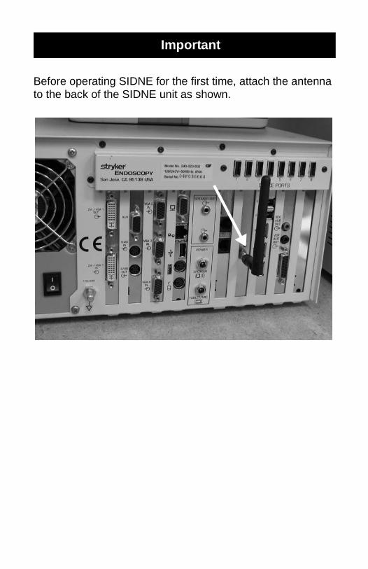
Before operating SIDNE for the first time, attach the antenna to the back of the SIDNE unit as shown.
Important
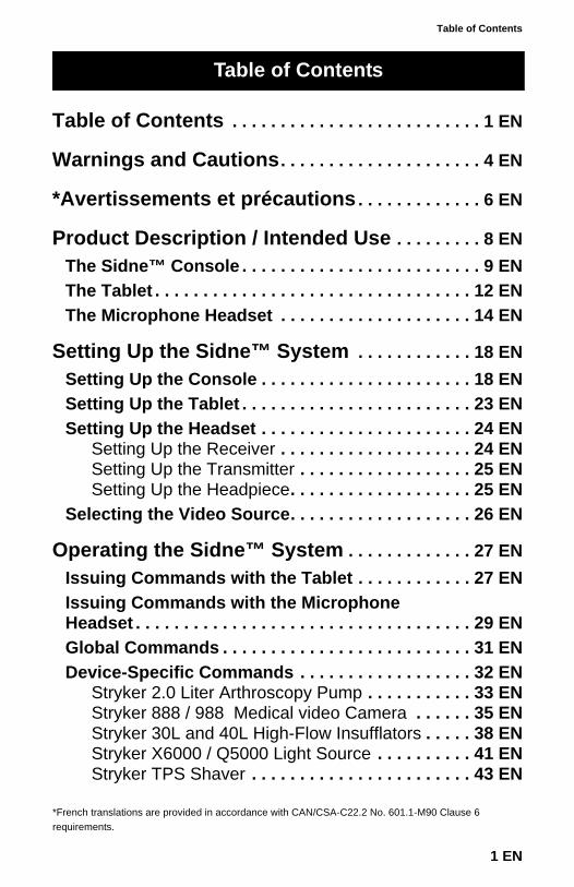
Table of Contents
Table of Contents . . . . . . . . . . . . . . . . . . . . . . . . . . 1 EN
Warnings and Cautions. . . . . . . . . . . . . . . . . . . . . 4 EN
*Avertissements et précautions. . . . . . . . . . . . . 6 EN
Product Description / Intended Use . . . . . . . . . 8 ENThe Sidne™ Console . . . . . . . . . . . . . . . . . . . . . . . . . 9 ENThe Tablet . . . . . . . . . . . . . . . . . . . . . . . . . . . . . . . . . 12 ENThe Microphone Headset . . . . . . . . . . . . . . . . . . . . 14 EN
Setting Up the Sidne™ System . . . . . . . . . . . . 18 ENSetting Up the Console . . . . . . . . . . . . . . . . . . . . . . 18 ENSetting Up the Tablet . . . . . . . . . . . . . . . . . . . . . . . . 23 ENSetting Up the Headset . . . . . . . . . . . . . . . . . . . . . . 24 EN
Setting Up the Receiver . . . . . . . . . . . . . . . . . . . . 24 ENSetting Up the Transmitter . . . . . . . . . . . . . . . . . . 25 ENSetting Up the Headpiece. . . . . . . . . . . . . . . . . . . 25 EN
Selecting the Video Source. . . . . . . . . . . . . . . . . . . 26 EN
Operating the Sidne™ System . . . . . . . . . . . . . 27 ENIssuing Commands with the Tablet . . . . . . . . . . . . 27 ENIssuing Commands with the Microphone Headset . . . . . . . . . . . . . . . . . . . . . . . . . . . . . . . . . . . 29 ENGlobal Commands . . . . . . . . . . . . . . . . . . . . . . . . . . 31 ENDevice-Specific Commands . . . . . . . . . . . . . . . . . . 32 EN
Stryker 2.0 Liter Arthroscopy Pump . . . . . . . . . . . 33 ENStryker 888 / 988 Medical video Camera . . . . . . 35 ENStryker 30L and 40L High-Flow Insufflators . . . . . 38 ENStryker X6000 / Q5000 Light Source . . . . . . . . . . 41 ENStryker TPS Shaver . . . . . . . . . . . . . . . . . . . . . . . 43 EN
Table of Contents
1 EN
*French translations are provided in accordance with CAN/CSA-C22.2 No. 601.1-M90 Clause 6 requirements.
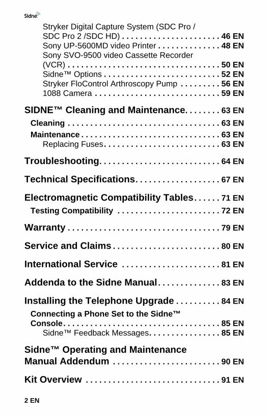
Stryker Digital Capture System (SDC Pro / SDC Pro 2 /SDC HD) . . . . . . . . . . . . . . . . . . . . . . 46 ENSony UP-5600MD video Printer . . . . . . . . . . . . . . 48 ENSony SVO-9500 video Cassette Recorder (VCR) . . . . . . . . . . . . . . . . . . . . . . . . . . . . . . . . . . 50 ENSidne™ Options . . . . . . . . . . . . . . . . . . . . . . . . . . 52 ENStryker FloControl Arthroscopy Pump . . . . . . . . . 56 EN1088 Camera . . . . . . . . . . . . . . . . . . . . . . . . . . . . 59 EN
SIDNE™ Cleaning and Maintenance. . . . . . . . 63 ENCleaning . . . . . . . . . . . . . . . . . . . . . . . . . . . . . . . . . . 63 ENMaintenance . . . . . . . . . . . . . . . . . . . . . . . . . . . . . . . 63 EN
Replacing Fuses . . . . . . . . . . . . . . . . . . . . . . . . . . 63 EN
Troubleshooting. . . . . . . . . . . . . . . . . . . . . . . . . . . 64 EN
Technical Specifications. . . . . . . . . . . . . . . . . . . 67 EN
Electromagnetic Compatibility Tables. . . . . . 71 ENTesting Compatibility . . . . . . . . . . . . . . . . . . . . . . . 72 EN
Warranty . . . . . . . . . . . . . . . . . . . . . . . . . . . . . . . . . . 79 EN
Service and Claims . . . . . . . . . . . . . . . . . . . . . . . . 80 EN
International Service . . . . . . . . . . . . . . . . . . . . . . 81 EN
Addenda to the Sidne Manual . . . . . . . . . . . . . . 83 EN
Installing the Telephone Upgrade . . . . . . . . . . 84 ENConnecting a Phone Set to the Sidne™ Console. . . . . . . . . . . . . . . . . . . . . . . . . . . . . . . . . . . 85 EN
Sidne™ Feedback Messages. . . . . . . . . . . . . . . . 85 EN
Sidne™ Operating and Maintenance Manual Addendum . . . . . . . . . . . . . . . . . . . . . . . . 90 EN
Kit Overview . . . . . . . . . . . . . . . . . . . . . . . . . . . . . . 91 EN
2 EN
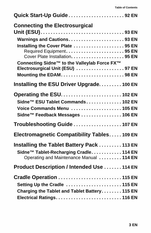
Table of Contents
Quick Start-Up Guide . . . . . . . . . . . . . . . . . . . . . . 92 EN
Connecting the Electrosurgical Unit (ESU). . . . . . . . . . . . . . . . . . . . . . . . . . . . . . . . . 93 EN
Warnings and Cautions. . . . . . . . . . . . . . . . . . . . . . 93 ENInstalling the Cover Plate . . . . . . . . . . . . . . . . . . . . 95 EN
Required Equipment . . . . . . . . . . . . . . . . . . . . . . . 95 ENCover Plate Installation. . . . . . . . . . . . . . . . . . . . . 95 EN
Connecting Sidne™ to the Valleylab Force FX™ Electrosurgical Unit (ESU) . . . . . . . . . . . . . . . . . . . 97 ENMounting the EDAM. . . . . . . . . . . . . . . . . . . . . . . . . 98 EN
Installing the ESU Driver Upgrade. . . . . . . . . 100 EN
Operating the ESU. . . . . . . . . . . . . . . . . . . . . . . . 102 ENSidne™ ESU Tablet Commands . . . . . . . . . . . . . . 102 ENVoice Commands Menu . . . . . . . . . . . . . . . . . . . . 105 ENSidne™ Feedback Messages . . . . . . . . . . . . . . . . 106 EN
Troubleshooting Guide . . . . . . . . . . . . . . . . . . . 107 EN
Electromagnetic Compatibility Tables. . . . . 109 EN
Installing the Tablet Battery Pack . . . . . . . . . 113 ENSidne™ Tablet-Recharging Cradle. . . . . . . . . . . . 114 EN
Operating and Maintenance Manual . . . . . . . . . 114 EN
Product Description / Intended Use . . . . . . . 114 EN
Cradle Operation . . . . . . . . . . . . . . . . . . . . . . . . . 115 ENSetting Up the Cradle . . . . . . . . . . . . . . . . . . . . . . 115 ENCharging the Tablet and Tablet Battery. . . . . . . . 115 ENElectrical Ratings. . . . . . . . . . . . . . . . . . . . . . . . . . 116 EN
3 EN

Cradle Cleaning and Maintenance. . . . . . . . . 117 ENCleaning . . . . . . . . . . . . . . . . . . . . . . . . . . . . . . . . . 117 ENMaintenance . . . . . . . . . . . . . . . . . . . . . . . . . . . . . . 117 EN
Warranty and Repairs . . . . . . . . . . . . . . . . . . . . 117 EN
4 EN
To avoid potential serious injury to the user and the patient and/or damage to this device, the user must:
1. Read this operating manual thoroughly and be familiar with its contents prior to using this equipment.
2. Carefully unpack the unit and check if any damage occurred during shipment. If damage is detected, please refer to the Service and Claims section in this manual.
3. Be a qualified physician, having complete knowledge of the use of this equipment.
4. Test this equipment prior to a surgical procedure. This unit was fully tested at the factory before shipment.
5. Attempt no internal repairs or adjustments not specifically detailed in this operating manual.
6. Pay close attention to the care and cleaning instructions in this manual. A deviation may cause damage.
7. Read the entire instruction manual before assembling or connecting the unit.
The warranty is void if any of these warnings are disregarded.
Stryker Endoscopy accepts full responsibility for the effects on safety, reliability, and performance of the equipment only if:
• Readjustments, modifications, and/or repairs are carried out exclusively by Stryker Endoscopy.
• The electrical installation of the relevant operating room complies with the applicable IEC, CEC, and NEC requirements.
Warning Federal law (United States of America) restricts this device to use by, or on order of, a physician.
Stryker Endoscopy reserves the right to make improvements on the product(s) described herein. Product(s), therefore, may not agree in detail to the published design or specifications. All specifications are subject to change without notice. Please contact the local Stryker Endoscopy Distributor listed in the International Service section, or phone your local Stryker Endoscopy sales representative or agent for information on changes and new products.
Warnings and Cautions
4 EN
Warnings and Cautions
Please read this manual and follow its instructions carefully. The words warning, caution, and note carry special meanings and should be carefully reviewed:
Warning The personal safety of the patient or physician may be involved. Disregarding this information could result in injury to the patient or physician.
Caution Special service procedures or precautions must be followed to avoid damaging the instrument.
Note Special information to make maintenance easier or important information more clear.
An exclamation mark within a triangle is intended to alert the user to the presence of important operating and maintenance instructions in the literature accompanying the product.
A lightning bolt within a triangle is intended to warn of the presence of hazardous voltage. Refer all service to authorized personnel.
Other Symbols:
FCC: Federal Communications Commission (United States)
IC: Industry Canada.Note The term “IC” before the certification/registration number
signifies that the Industry Canada technical specifications were met.
This device complies with Part 15 of the FCC rules. Operation is subject to the following 2 conditions: (1) This device may not cause harmful interference, and (2) This device must accept any interference received, including interference that may cause undesired operation.
Ambient temperature range
Relative humidity range
Atmospheric pressure range
Denotes compliance to CSA C22.2 No. 601.1-M90, and UL 2601-1.This device includes RF transmitters and emits nonionizing radiation.
5 EN
Pour evictor de graves pleasures potentiates à l’utilisateur et au patient et/ou des dégâts à ce dispositif, l’utilisateur doit répondre à certaines conditions et/ou suivre certaines cédures :
1. Lire intégralement ce manuel d’utilisation et se familiariser avec son contenu avant d’utiliser cet équipement.
2. Déballer l’unité avec précaution et vérifier les dommages éventuels survenus pendant l’expédition. Si l’unité n’est pas intacte, se reporter à la section Assistance et réclamations de ce manuel.
3. Être un médecin qualifié parfaitement au courant des modalités l’utilisation de cet équipement.
4. Tester cet équipement avant toute intervention chirurgicale. L’unité a subi des tests poussés en usine avant son expédition.
5. Ne tenter aucun réglage ou réparation qui ne soit pas spécifiquement décrit dans ce manuel d’utilisation.
6. Suivre scrupuleusement les instructions d'entretien et de nettoyage exposées dans ce manuel. Tout manquement peut être source de dégâts.
7. Lire intégralement le mode d’emploi avant d'assembler ou de connecter l’unité.
Le non-respect de ces mises en garde entraîne la nullité de la garantie.
Stryker Endoscopy n’accepte la pleine responsabilité quant aux effets nuisibles sur la sécurité, la fiabilité et les performances de l’équipement que dans les conditions suivantes :
• Les réglages, modifications et/ou réparations sont exécutées exclusivement par Stryker Endoscopy.
• L’installation électrique de la salle d'opération où cet équipement est utilisé est conforme aux normes CEI, CEC et NEC en vigueur.
Avertissement Selon la loi fédérale américaine, ce dispositif ne peut être utilisé que par un médecin ou sur son ordre.
Stryker Endoscopy se réserve le droit d’apporter des améliorations au(x) duit(s) décrit(s) dans le présent document. Il se peut par conséquent que l’équipement utilisé diffère légèrement dans sa conception et ses spécifications de l’équipement décrit. Toutes les spécifications sont sujettes à modification sans préavis. Prendre contact avec le distributeur Stryker Endoscopy le plus che dont les coordonnées sont indiquées dans la section Autres services d’assistance ou appeler le représentant ou
*Avertissements et précautions
6 EN
*Avertissements et précautions
l’agent Stryker Endoscopy local pour obtenir des informations sur les modifications et les nouveaux duits.
Lire ce manuel et suivre scrupuleusement les instructions qu’il contient. Les termes Warning (avertissement), Caution (attention) et Note (remarque) ont une importance particulière décrite ci-dessous :
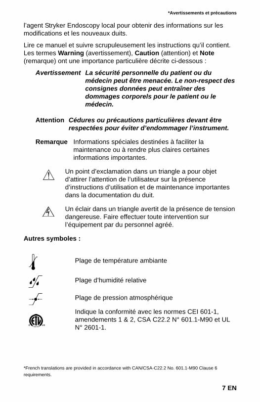
Avertissement La sécurité personnelle du patient ou du médecin peut être menacée. Le non-respect des consignes données peut entraîner des dommages corporels pour le patient ou le médecin.
Attention Cédures ou précautions particulières devant être respectées pour éviter d’endommager l’instrument.
Remarque Informations spéciales destinées à faciliter la maintenance ou à rendre plus claires certaines informations importantes.
Un point d’exclamation dans un triangle a pour objet d’attirer l’attention de l’utilisateur sur la présence d’instructions d’utilisation et de maintenance importantes dans la documentation du duit.
Un éclair dans un triangle avertit de la présence de tension dangereuse. Faire effectuer toute intervention sur l’équipement par du personnel agréé.
Autres symboles :
Plage de température ambiante
Plage d’humidité relative
Plage de pression atmosphérique
Indique la conformité avec les normes CEI 601-1, amendements 1 & 2, CSA C22.2 N° 601.1-M90 et UL N° 2601-1.
*French translations are provided in accordance with CAN/CSA-C22.2 No. 601.1-M90 Clause 6 requirements.
7 EN
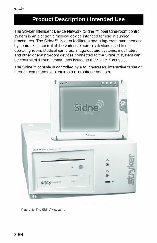
The Stryker Intelligent Device Network (Sidne™) operating-room control system is an electronic medical device intended for use in surgical procedures. The Sidne™ system facilitates operating-room management by centralizing control of the various electronic devices used in the operating room. Medical cameras, image capture systems, insufflators, and other operating-room devices connected to the Sidne™ system can be controlled through commands issued to the Sidne™ console.
The Sidne™ console is controlled by a touch-screen, interactive tablet or through commands spoken into a microphone headset.
Figure 1: The Sidne™ system.
Product Description / Intended Use
8 EN
Product Description / Intended Use
The Sidne™ system is packaged with the following components:
1 Sidne™ console
1 tablet
1 Audio-Technica wireless headset kit
8 6-foot Serial USB device-connector cables
1 Hospital-grade AC power cord
1 Speaker power cable
1 Tablet power cable
1 12-foot S-video cable
1 video-out cable
1 Audio-out cable (SDC compatible)
1 Audio-out cable (VCR compatible)
1 Audio-Technica Line cable
The three main components of the Sidne™ system are1. The Sidne™ console2. The remote-control tablet3. The microphone headset.
Each of these three main components is described in detail in the following pages.
The Sidne™ ConsoleThe Sidne™ console is the primary component of the Sidne™ system. The console provides connection ports for the various operating- room devices, which it controls by processing voice and tablet commands issued by the surgeon and operating-room staff. The front console panel provides several features whose functions are listed in Figure 2 below. Figure 3 lists the features of the rear console panel.
9 EN
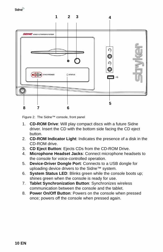
Figure 2: The Sidne™ console, front panel
1. CD-ROM Drive: Will play compact discs with a future Sidne driver. Insert the CD with the bottom side facing the CD eject button.
2. CD-ROM Indicator Light: Indicates the presence of a disk in the CD-ROM drive.
3. CD Eject Button: Ejects CDs from the CD-ROM Drive.4. Microphone Headset Jacks: Connect microphone headsets to
the console for voice-controlled operation.5. Device-Driver Dongle Port: Connects to a USB dongle for
uploading device drivers to the Sidne™ system.6. System Status LED: Blinks green while the console boots up;
shines green when the console is ready for use.7. Tablet Synchronization Button: Synchronizes wireless
communication between the console and the tablet.8. Power On/Off Button: Powers on the console when pressed
once; powers off the console when pressed again.
8 7 65
4321
10 EN
Product Description / Intended Use
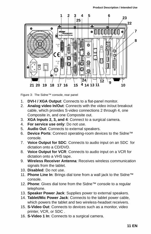
Figure 3: The Sidne™ console, rear panel
1. DVI-I / XGA Output: Connects to a flat-panel monitor.2. Analog video In/Out: Connects with the video in/out breakout
cable, which provides S-video connections 2 through 4, one Composite in, and one Composite out.
3. XGA Inputs 2, 3, and 4: Connect to a surgical camera.4. For service use only: Do not use.5. Audio Out: Connects to external speakers.6. Device Ports: Connect operating-room devices to the Sidne™
console.7. Voice Output for SDC: Connects to audio input on an SDC for
dictation onto a CD/DVD.8. Voice Output for VCR: Connects to audio input on a VCR for
dictation onto a VHS tape.9. Wireless Receiver Antenna: Receives wireless communication
signals from the tablet.10. Disabled: Do not use.11. Phone Line In: Brings dial tone from a wall jack to the Sidne™
console.12. Phone: Gives dial tone from the Sidne™ console to a regular
telephone.13. Speaker Power Jack: Supplies power to external speakers.14. Tablet/Mic Power Jack: Connects to the tablet power cable,
which powers the tablet and two wireless-headset receivers.15. S-Video Out: Connects to devices such as a monitor, video
printer, VCR, or SDC .16. S-Video 1 In: Connects to a surgical camera.
1 2 3 4 5 6
7
8
1011 9131415161718192021
2322
12424
25
11 EN
17. DVI-I / XGA-1 Input: Connects to a surgical camera.18. Equipotential Ground Terminal19. Power On / Off Switch: Enables the system to power on when in
the “I” position; powers off the system when in the “O” position20. Voltage Selector: Selects either 120 or 240 Volts.21. AC-Power Supply Input 22. USB 2.0 Ports: Reserved for future use.23. Firewire Ports: Reserved for future use.24. USB 1.1 Port: Reserved for future use. 25. Ethernet Port: Reserved for future use.
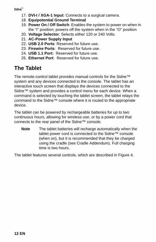
The TabletThe remote-control tablet provides manual controls for the Sidne™ system and any devices connected to the console. The tablet has an interactive touch screen that displays the devices connected to the Sidne™ system and provides a control menu for each device. When a command is selected by touching the tablet screen, the tablet relays the command to the Sidne™ console where it is routed to the appropriate device.
The tablet can be powered by rechargeable batteries for up to two continuous hours, allowing for wireless use, or by a power cord that connects to the rear panel of the Sidne™ console.
Note The tablet batteries will recharge automatically when the tablet power cord is connected to the Sidne™ console (when on), but it is recommended that they be charged using the cradle (see Cradle Addendum). Full charging time is two hours.
The tablet features several controls, which are described in Figure 4.
12 EN
Product Description / Intended Use
Figure 4: The remote-control tablet, front and right-side view
1. Tablet Indicator Light: Shines orange while the tablet boots up; shines green when the tablet is ready for use.
2. Battery Indicator Light: Indicates the charge left in the tablet battery: Green = over 80%; Orange = between 80% and 20%; Red = less than 20%.
3. Touch/View screen: Displays control menus for operating the Sidne™ system and any devices connected to it.
4. On-Screen Keyboard Button: Displays / hides the on-screen keyboard when pressed.
5. DC Power Input: Connects the tablet to the Sidne™ console for DC power and battery recharging.
6. Power On/Off Switch: Powers the tablet on or off when held for 3 continuous seconds. Suspends the tablet if pressed and released quickly. To activate, press button again.
7. Stylus: Acts as a pointer to select options on the tablet touch screen. Pull gently on the stylus to release it from its housing.
Caution The extra ports and buttons on the tablet not described in this manual are not intended for use and may cause unexpected results if used.
7654321
13 EN
Caution Do not open the battery compartment or try to replace the batteries as battery function may be compromised. Contact your local Stryker representative for assistance.
The Microphone HeadsetThe microphone headset provides voice-activated control of the Sidne™ system and any devices connected to the console. When a command is spoken into the microphone headset, the headset transmits the command via radio frequency to the Sidne™ console, where it is then routed to the appropriate device.
The headset comprises three main components, which are described in Figures 5 through 8 below:
1. The headset (Figure 5)2. The transmitter (Figure 6)3. The receiver (front panel Figure 7; rear panel Figure 8).
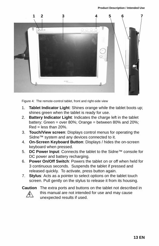
Figure 5: The headset
1. Headpiece: Fits over the top of the head or above the ear and behind the head, positioning the microphone in front of the mouth.
2. Microphone Mouthpiece: Fits three fingers’ breadth away from the corner of the mouth to receive spoken commands.
3. Headpiece Connector: Connects to the transmitter.
3
2
1
14 EN
Product Description / Intended Use
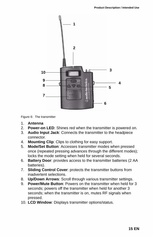
Figure 6: The transmitter
1. Antenna 2. Power-on LED: Shines red when the transmitter is powered on.3. Audio Input Jack: Connects the transmitter to the headpiece
connector.4. Mounting Clip: Clips to clothing for easy support.5. Mode/Set Button: Accesses transmitter modes when pressed
once (repeated pressing advances through the different modes); locks the mode setting when held for several seconds.
6. Battery Door: provides access to the transmitter batteries (2 AA batteries).
7. Sliding Control Cover: protects the transmitter buttons from inadvertent selections.
8. Up/Down Arrows: Scroll through various transmitter settings.9. Power/Mute Button: Powers on the transmitter when held for 3
seconds; powers off the transmitter when held for another 3 seconds; when the transmitter is on, mutes RF signals when pressed.
10. LCD Window: Displays transmitter options/status.
1
2
3
45
7
89
6
10
15 EN
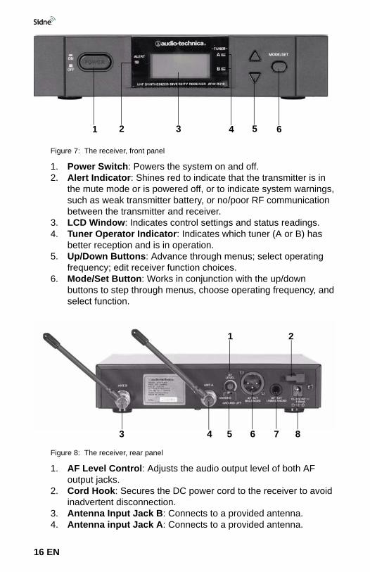
Figure 7: The receiver, front panel
1. Power Switch: Powers the system on and off.2. Alert Indicator: Shines red to indicate that the transmitter is in
the mute mode or is powered off, or to indicate system warnings, such as weak transmitter battery, or no/poor RF communication between the transmitter and receiver.
3. LCD Window: Indicates control settings and status readings.4. Tuner Operator Indicator: Indicates which tuner (A or B) has
better reception and is in operation.5. Up/Down Buttons: Advance through menus; select operating
frequency; edit receiver function choices.6. Mode/Set Button: Works in conjunction with the up/down
buttons to step through menus, choose operating frequency, and select function.
Figure 8: The receiver, rear panel
1. AF Level Control: Adjusts the audio output level of both AF output jacks.
2. Cord Hook: Secures the DC power cord to the receiver to avoid inadvertent disconnection.
3. Antenna Input Jack B: Connects to a provided antenna.4. Antenna input Jack A: Connects to a provided antenna.
1 2 3 4 5 6
1 2
3 4 5 6 7 8
16 EN

Product Description / Intended Use
5. Ground Lift Switch: Disconnects the ground pin of the balanced output jack (6) from ground. Slide the switch to the right to eliminate humming caused by a ground loop; otherwise, slide the switch to the left for regular use.
6. Balanced Audio Output Jack: Connects to an XLRM-type connector to connect the receiver to a mixer or integrated amplifier.
7. Unbalanced Audio Output Jack: Connects to an unbalanced mixer.
8. Power Input Jack: Connects to the DC plug from the Sidne™ console.
17 EN
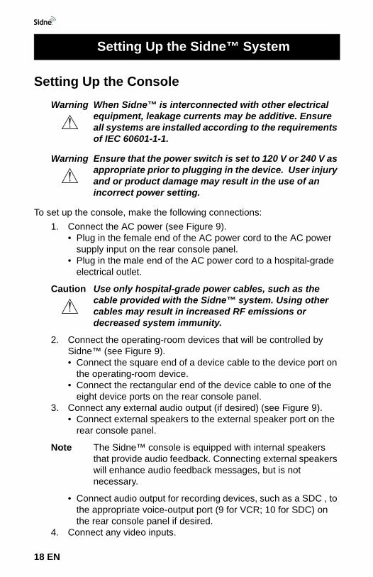
Setting Up the ConsoleWarning When Sidne™ is interconnected with other electrical
equipment, leakage currents may be additive. Ensure all systems are installed according to the requirements of IEC 60601-1-1.
Warning Ensure that the power switch is set to 120 V or 240 V as appropriate prior to plugging in the device. User injury and or product damage may result in the use of an incorrect power setting.
To set up the console, make the following connections:1. Connect the AC power (see Figure 9).
• Plug in the female end of the AC power cord to the AC power supply input on the rear console panel.
• Plug in the male end of the AC power cord to a hospital-grade electrical outlet.
Caution Use only hospital-grade power cables, such as the cable provided with the Sidne™ system. Using other cables may result in increased RF emissions or decreased system immunity.
2. Connect the operating-room devices that will be controlled by Sidne™ (see Figure 9).• Connect the square end of a device cable to the device port on
the operating-room device.• Connect the rectangular end of the device cable to one of the
eight device ports on the rear console panel.3. Connect any external audio output (if desired) (see Figure 9).
• Connect external speakers to the external speaker port on the rear console panel.
Note The Sidne™ console is equipped with internal speakers that provide audio feedback. Connecting external speakers will enhance audio feedback messages, but is not necessary.
• Connect audio output for recording devices, such as a SDC , to the appropriate voice-output port (9 for VCR; 10 for SDC) on the rear console panel if desired.
4. Connect any video inputs.
Setting Up the Sidne™ System
18 EN
Setting Up the Sidne™ System
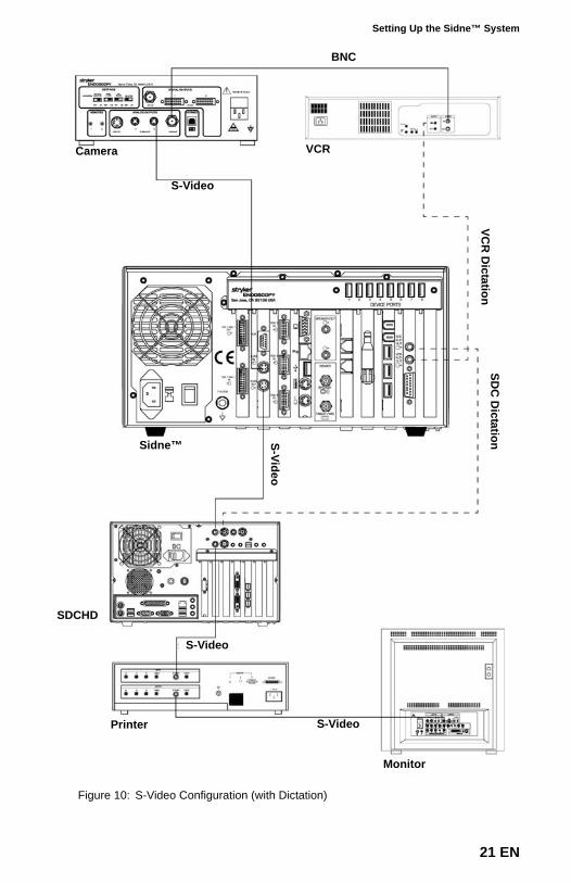
• Connect video inputs, such as cameras, to an XGA port (see Figure 11), or a S-Video port (see Figure 10).
• To take advantage of the high definition support provided by Sidne™, connect the DVI/XGA inputs to a high definition camera system such as the Stryker 1088 Medical Video Camera. Ensure that the camera is set to high definition mode.
5. Connect any video outputs.• Connect any video outputs, such as monitors or recording
devices, to the S-video-out port (see Figure 10).
Note When connecting video and audio inputs and outputs, make Sidne™ the first connection in the loop. For example, rather than connect a camera directly to a monitor or recording device, connect it directly to Sidne™. After connecting the camera to Sidne™, connect the monitor and recording device to Sidne™.
6. Connect Sidne™ to a telephone line if desired (see Figure 9).
Note The telephone option is only available if the supplemental telephone driver has been installed.
• Connect a telephone cord from a telephone wall jack to the line-in jack on the rear Sidne™ console.
• Connect any external telephone to the phone jack on the rear Sidne™ console.
7. Connect the tablet (see Setting Up the Tablet) and the headset (see Setting Up the Headset) (see also Figure 9).
8. Apply power to the devices connected to the Sidne™ console.9. Apply power to the Sidne™ console.
• For first use only: Switch the on/off switch on the rear console panel to on (represented by the “I” symbol).
Note Turning on the unit using the on/off switch on the rear console panel will fully power up the unit. In this case, it is not necessary to press the on/off button on the front console panel.
• For every subsequent use: Press the on/off button on the front console panel to activate the system.
• After the Sidne™ system boots up, the console says, “Greetings. One moment please. Sidne™ ready.” The Sidne™ system will review the connected operating-room devices, list them in order, and announce any device error conditions. For example: “Insufflator/ Camera/ VCR connected.”
19 EN
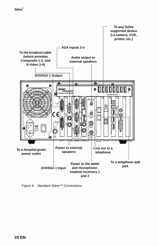
Figure 9: Standard Sidne™ Connections
To a telephone wall jack
Line out to a telephone
Power to external speakers
Power to the tablet and microphone-
headset receivers 1 and 2
XGA inputs 2-4
To any Sidne supported device (i.e.camera, VCR,
printer, etc.)
Audio output to external speakers
To a hospital-grade power outlet
To the breakout cable (which provides
Composite 1-2, and S-Video 2-4)
DVI/XGA 1 Input
DVI/XGA 1 Output
20 EN
Setting Up the Sidne™ System
Figure 10: S-Video Configuration (with Dictation)
Camera VCR
S-Video
Sidne™
SDCHD
S-Video
S-VideoPrinter
BNC
Monitor
VCR
Dictation
SDC
DictationS-Video
21 EN
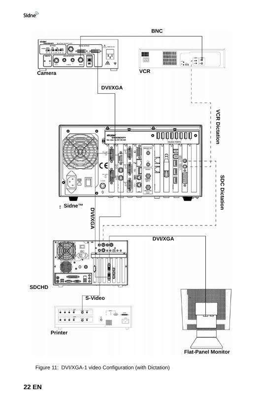
Figure 11: DVI/XGA-1 video Configuration (with Dictation)
Camera VCR
Sidne™
SDCHD
Printer
VCR
Dictation
SDC
Dictation
S-Video
Flat-Panel Monitor
DVI/XGA
DVI/XGA
BNC
DVI/XG
A
22 EN

Setting Up the Sidne™ System
Setting Up the TabletRefer to the Wired Tablet Insert for Tablet setup instructions.
23 EN
Setting Up the HeadsetNote For more information on the microphone headset, consult
3000 Series Professional UHF Wireless Systems, the user manual packaged with the headset.
Setting Up the Receiver1. Attach the two provided antennae to the rear receiver panel.2. Position the receiver on a stable surface near the Sidne™
console.3. Connect the power cord.
• Connect one end to the power input jack on the rear receiver panel.
• Connect the other end to the 16-volt power jack on the rear Sidne™ console panel.
4. Connect the receiver cable.• Connect one end to the unbalanced audio output jack on the
rear receiver panel.• Connect the other end to one of the microphone headset jacks
on the front Sidne™ console panel. 5. Power on the receiver. (The receiver will only power on if the
Sidne™ console is powered on.)• The LCD screen will read “WAIT”.• The alert indicator will shine red until the transmitter is powered
on.
24 EN
Setting Up the Sidne™ System
Setting Up the Transmitter
Warning To maintain sterility in the surgical field, set up the transmitter and headpiece prior to scrubbing for surgery.
1. Ensure the batteries are installed in the transmitter.• Release the battery door and insert two AA batteries, observing
polarity.• Close the battery door.
2. Power on the transmitter by holding the power button for three continuous seconds.
3. Select an operating frequency for the transmitter.
Note This frequency should match the frequency chosen for the receiver in order for the headset to communicate properly. For more information on selecting an operating frequency, consult 3000 Series Professional UHF Wireless Systems, the user manual packaged with the headset.
• Press the set button on the transmitter two times. “Edit” appears on the LCD window.
• Press the up or down arrows to select the desired frequency.• Hold the set button until the LCD reads “STORED.”• Slide the sliding control cover over the buttons to protect
against inadvertent button selections.4. Select the same operating frequency for the receiver.
• Press the set button on the receiver two times.• Press the up or down arrows to select the same frequency
selected on the transmitter.• Hold the set button until the LCD reads “STORED.”• Press the down arrow until “QUIT” appears on the LCD.• Press the set button until the status bar shows on the LCD.
5. Clip the transmitter to an article of clothing away from the hands and operating site.
Setting Up the Headpiece
Warning To maintain sterility in the surgical field, set up the transmitter and headpiece prior to scrubbing for surgery.
1. Connect the headpiece connector to the audio-input jack on the transmitter.
25 EN
2. Position the headset over the head so the mouthpiece rests three finger’s breadth from the corner of the mouth.
3. Clip any excess cords to the back of the surgical gown.
Note Repeat the steps listed under “Setting Up the Headset” if a second headset will be connected to the Sidne™ console.
Selecting the Video SourceIn order to display the camera image properly, Sidne™ must know where the camera has been connected. Use the tablet or microphone headset to tell Sidne™ which video input port the camera is connected to. (For more information on navigating tablet and voice-command menus, see the Operating the Sidne™ System and Sidne™ Options sections in this manual.)
1. To select the video source by using the tablet,• Press the Options icon on the tablet screen.• Press the icon that corresponds with the video source (input
port) the camera is connected to. 2. To select the video source by using the microphone headset,
• Say “Sidne™.”• Say “Options” (after Options has appeared on the monitor).• Say “Source” (after Source has appeared on the monitor).• Say the name of the video input port the camera is connected
to (after it has appeared on the monitor).
26 EN
Operating the Sidne™ System
Warning Sidne™ is not intended for use with robotic surgical systems. Using Sidne™ with a robotic surgical system may cause unexpected results and harm the patient.
Warning To maintain harmony with existing hospital networks, notify hospital IT staff that Sidne™ uses an 802.11b wireless network before using the system in the operating room.
The Sidne™ system and the devices connected to it can be controlled by commands issued through either the tablet or the microphone headset. Sidne™ provides both audio and visual feedback to acknowledge commands. Visual feedback appears on the tablet screen when the tablet is used, and on the operating-room monitor when the microphone headset is used.
Note All devices connected to the Sidne™ system can still be operated by their front-panel controls. They will continue to function even if Sidne™ is powered off.
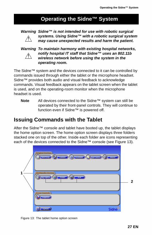
Issuing Commands with the TabletAfter the Sidne™ console and tablet have booted up, the tablet displays the home option screen. The home option screen displays three folders stacked one on top of the other. Inside each folder are icons representing each of the devices connected to the Sidne™ console (see Figure 13).
Figure 13: The tablet home option screen
Operating the Sidne™ System
2
1
27 EN
1. Folders2. Device icons
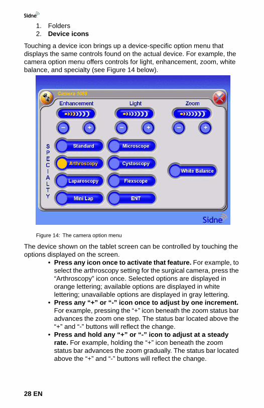
Touching a device icon brings up a device-specific option menu that displays the same controls found on the actual device. For example, the camera option menu offers controls for light, enhancement, zoom, white balance, and specialty (see Figure 14 below).
Figure 14: The camera option menu
The device shown on the tablet screen can be controlled by touching the options displayed on the screen.
• Press any icon once to activate that feature. For example, to select the arthroscopy setting for the surgical camera, press the “Arthroscopy” icon once. Selected options are displayed in orange lettering; available options are displayed in white lettering; unavailable options are displayed in gray lettering.
• Press any “+” or “-” icon once to adjust by one increment. For example, pressing the “+” icon beneath the zoom status bar advances the zoom one step. The status bar located above the “+” and “-” buttons will reflect the change.
• Press and hold any “+” or “-” icon to adjust at a steady rate. For example, holding the “+” icon beneath the zoom status bar advances the zoom gradually. The status bar located above the “+” and “-” buttons will reflect the change.
28 EN
Operating the Sidne™ System
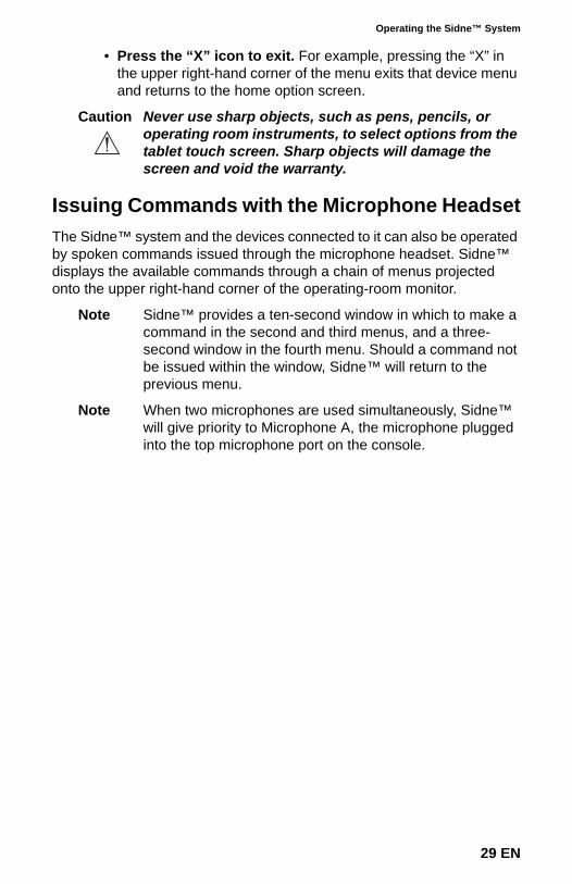
• Press the “X” icon to exit. For example, pressing the “X” in the upper right-hand corner of the menu exits that device menu and returns to the home option screen.
Caution Never use sharp objects, such as pens, pencils, or operating room instruments, to select options from the tablet touch screen. Sharp objects will damage the screen and void the warranty.
Issuing Commands with the Microphone HeadsetThe Sidne™ system and the devices connected to it can also be operated by spoken commands issued through the microphone headset. Sidne™ displays the available commands through a chain of menus projected onto the upper right-hand corner of the operating-room monitor.
Note Sidne™ provides a ten-second window in which to make a command in the second and third menus, and a three-second window in the fourth menu. Should a command not be issued within the window, Sidne™ will return to the previous menu.
Note When two microphones are used simultaneously, Sidne™ will give priority to Microphone A, the microphone plugged into the top microphone port on the console.
29 EN
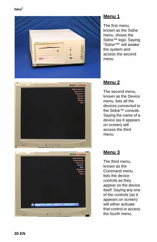
Menu 1
The first menu, known as the Sidne menu, shows the Sidne™ logo. Saying “Sidne™” will awake the system and access the second menu.
Menu 2
The second menu, known as the Device menu, lists all the devices connected to the Sidne™ console. Saying the name of a device (as it appears on screen) will access the third menu.
Menu 3
The third menu, known as the Command menu, lists the device controls as they appear on the device itself. Saying any one of the controls (as it appears on screen) will either activate that control or access the fourth menu.
30 EN
Operating the Sidne™ System
Global CommandsAlthough most voice commands can be issued only from their respective menus, some voice commands are available from more than one menu.
2 voice commands may be issued at any time and from any menu (Menus 1-4):
1. “Sidne”: Saying “Sidne” will take the system to Menu 2 (Device Menu), where all available devices are listed on the upper right-hand corner of the operating-room monitor.
2. “Image Capture”: Saying “Image capture” will capture the image displayed on the monitor to a recording device.
5 voice commands may be issued at any time from Menus 2-4 (These commands are not available from Menu 1):
1. “Exit”: Saying “Exit” at any menu will take the system to the Sidne™ menu (Menu 1).
2. “Picture”: Saying “Picture” will capture the image displayed on the monitor and print it out on any connected printer.
3. “Show Status”: Saying “Show Status” while in the Command menu of any device will display the status bar of the device onscreen at all times. For example, saying “Show Status” in the Arthropump Command menu will display the Arthropump status bar onscreen at all times. Saying “Sidne” will return the display to the Device menu, while continuing to display the Arthropump
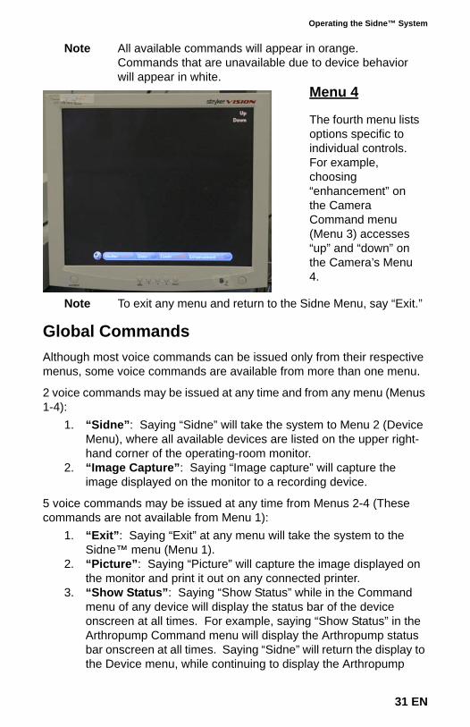
Note All available commands will appear in orange. Commands that are unavailable due to device behavior will appear in white.
Menu 4
The fourth menu lists options specific to individual controls. For example, choosing “enhancement” on the Camera Command menu (Menu 3) accesses “up” and “down” on the Camera’s Menu 4.
Note To exit any menu and return to the Sidne Menu, say “Exit.”
31 EN
status bar. The display bar will remain on the Device menu and Sidne™ menu until the user says “Hide Status.”
4. “Hide Status”: Saying “Hide Status” will hide the status bar on the Device menu or Sidne™ menu.
5. “Shaver Stop”: Saying “Shaver Stop” issues a “Stop” command to any shaver connected to the system.
Device-Specific CommandsThe Sidne™ system is compatible with a wide variety of “Sidne™-smart” operating-room devices, such as the devices listed below:
Each of these devices has its own set of voice and tablet commands, as well as a unique set of audio feedback messages that come from the Sidne™ console. Tablet-command menus and voice-command menus for each device are listed in the following pages.
Note Should the Sidne™ system list a device as “unknown,” a device driver may need to be loaded onto the Sidne™ console to enable compatibility. Contact a Stryker representative to determine compatibility with the Sidne™ system and to acquire a device driver. To load the device driver onto the Sidne™ system, insert the device-driver dongle into the device-driver dongle port on the front console panel and follow the instructions spoken by Sidne™. Please refer to the user addendum for the specific device for more information.
• 1088 Digital Camera• 988 Digital Camera• 888 3-Chip Camera• 688 1-Chip Camera• SDC Pro• SDC Pro2• SDC HD• X6000 Xenon Light
Source• Q5000 Light Source• TPS Arthroscopy
Shaver
• 40L High Flow Insufflator
• 30L High Flow Insufflator
• 2.0L Arthroscopy Pump• Toshiba Mega-Hi Printer• Sony MD51 Printer• Sony UP5600 Printer• Sony 9500 VCR• Sony 2100 VCR• Telephone*• FloControl Pump• Valley Lab ESU*
*These drivers are available for purchase. Contact your local Stryker Representative for ordering information.
32 EN
Operating the Sidne™ System
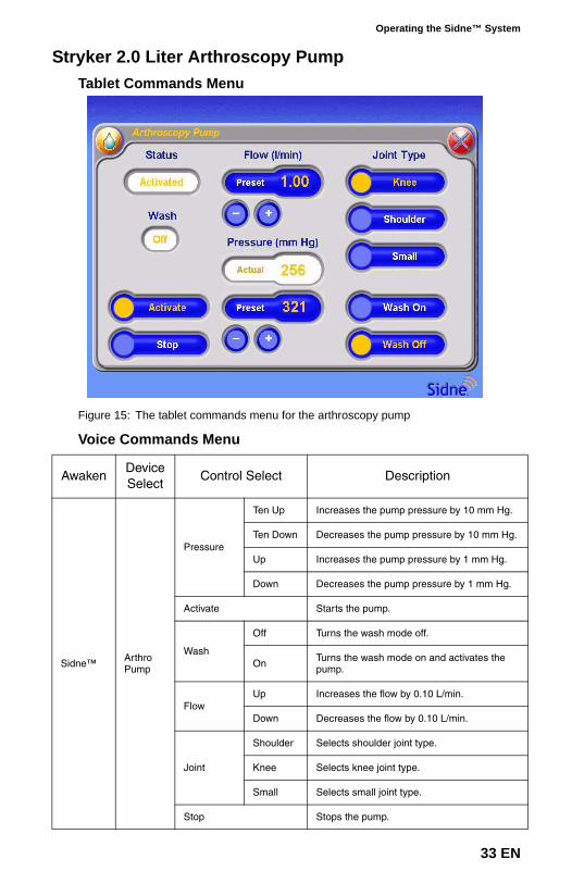
Stryker 2.0 Liter Arthroscopy PumpTablet Commands Menu
Figure 15: The tablet commands menu for the arthroscopy pump
Voice Commands Menu
AwakenDevice Select
Control Select Description
Sidne™ Arthro Pump
Pressure
Ten Up Increases the pump pressure by 10 mm Hg.
Ten Down Decreases the pump pressure by 10 mm Hg.
Up Increases the pump pressure by 1 mm Hg.
Down Decreases the pump pressure by 1 mm Hg.
Activate Starts the pump.
Wash
Off Turns the wash mode off.
On Turns the wash mode on and activates the pump.
FlowUp Increases the flow by 0.10 L/min.
Down Decreases the flow by 0.10 L/min.
Joint
Shoulder Selects shoulder joint type.
Knee Selects knee joint type.
Small Selects small joint type.
Stop Stops the pump.
33 EN
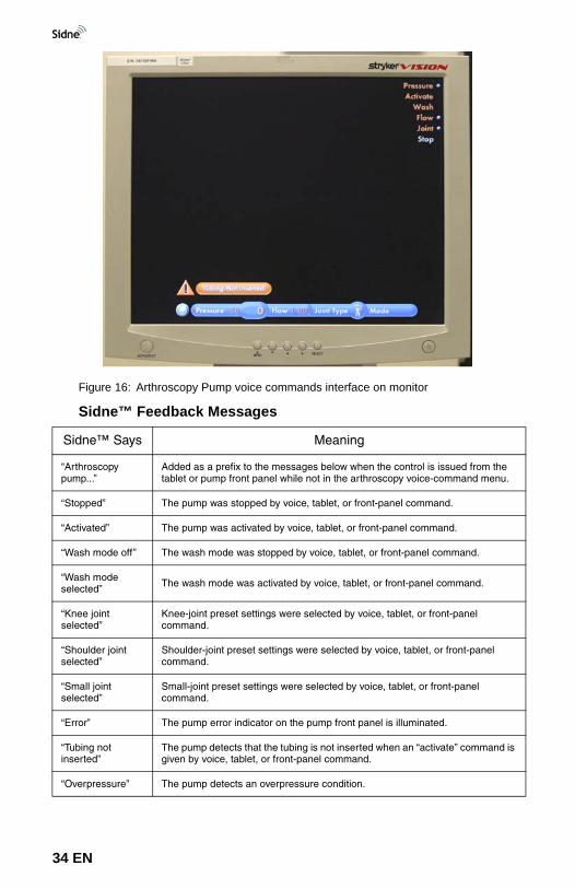
Figure 16: Arthroscopy Pump voice commands interface on monitor
Sidne™ Feedback Messages
Sidne™ Says Meaning
“Arthroscopy pump...”
Added as a prefix to the messages below when the control is issued from the tablet or pump front panel while not in the arthroscopy voice-command menu.
“Stopped” The pump was stopped by voice, tablet, or front-panel command.
“Activated” The pump was activated by voice, tablet, or front-panel command.
“Wash mode off” The wash mode was stopped by voice, tablet, or front-panel command.
“Wash mode selected” The wash mode was activated by voice, tablet, or front-panel command.
“Knee joint selected”
Knee-joint preset settings were selected by voice, tablet, or front-panel command.
“Shoulder joint selected”
Shoulder-joint preset settings were selected by voice, tablet, or front-panel command.
“Small joint selected”
Small-joint preset settings were selected by voice, tablet, or front-panel command.
“Error” The pump error indicator on the pump front panel is illuminated.
“Tubing not inserted”
The pump detects that the tubing is not inserted when an “activate” command is given by voice, tablet, or front-panel command.
“Overpressure” The pump detects an overpressure condition.
34 EN
Operating the Sidne™ System
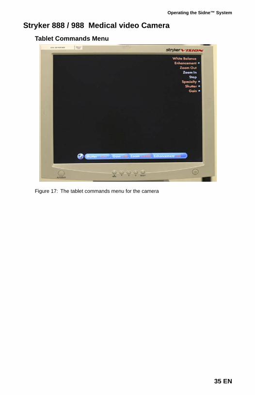
Stryker 888 / 988 Medical video CameraTablet Commands Menu
Figure 17: The tablet commands menu for the camera
35 EN
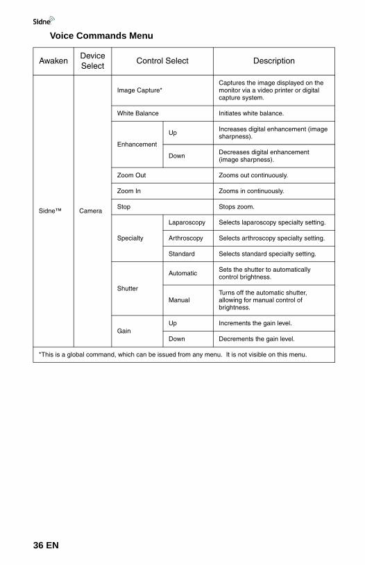
Voice Commands Menu
AwakenDevice Select
Control Select Description
Sidne™ Camera
Image Capture*Captures the image displayed on the monitor via a video printer or digital capture system.
White Balance Initiates white balance.
Enhancement
Up Increases digital enhancement (image sharpness).
Down Decreases digital enhancement (image sharpness).
Zoom Out Zooms out continuously.
Zoom In Zooms in continuously.
Stop Stops zoom.
Specialty
Laparoscopy Selects laparoscopy specialty setting.
Arthroscopy Selects arthroscopy specialty setting.
Standard Selects standard specialty setting.
Shutter
Automatic Sets the shutter to automatically control brightness.
ManualTurns off the automatic shutter, allowing for manual control of brightness.
GainUp Increments the gain level.
Down Decrements the gain level.
*This is a global command, which can be issued from any menu. It is not visible on this menu.
36 EN
Operating the Sidne™ System
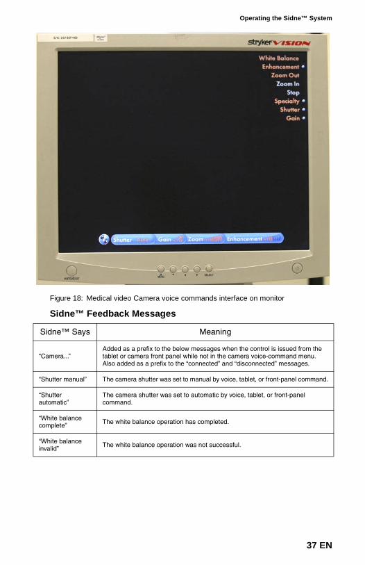
Figure 18: Medical video Camera voice commands interface on monitor
Sidne™ Feedback Messages
Sidne™ Says Meaning
“Camera...”Added as a prefix to the below messages when the control is issued from the tablet or camera front panel while not in the camera voice-command menu. Also added as a prefix to the “connected” and “disconnected” messages.
“Shutter manual” The camera shutter was set to manual by voice, tablet, or front-panel command.
“Shutter automatic”
The camera shutter was set to automatic by voice, tablet, or front-panel command.
“White balance complete” The white balance operation has completed.
“White balance invalid” The white balance operation was not successful.
37 EN
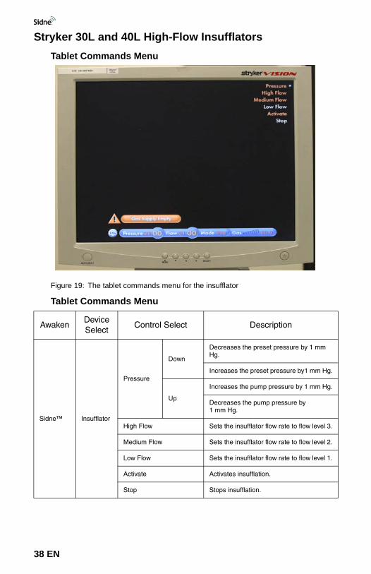
Stryker 30L and 40L High-Flow InsufflatorsTablet Commands Menu
Figure 19: The tablet commands menu for the insufflator
Tablet Commands Menu
AwakenDevice Select
Control Select Description
Sidne™ Insufflator
Pressure
Down
Decreases the preset pressure by 1 mm Hg.
Increases the preset pressure by1 mm Hg.
Up
Increases the pump pressure by 1 mm Hg.
Decreases the pump pressure by 1 mm Hg.
High Flow Sets the insufflator flow rate to flow level 3.
Medium Flow Sets the insufflator flow rate to flow level 2.
Low Flow Sets the insufflator flow rate to flow level 1.
Activate Activates insufflation.
Stop Stops insufflation.
38 EN
Operating the Sidne™ System
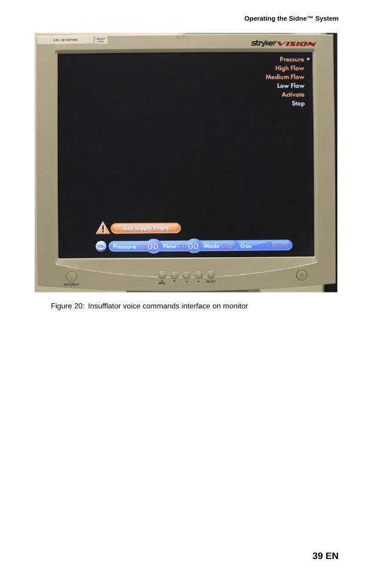
Figure 20: Insufflator voice commands interface on monitor
39 EN
Sidne™ Feedback Messages
Sidne™ Says Meaning
“Insufflator...” Added as a prefix to the below messages when the control is issued by the tablet or insufflator front panel while not in the insufflator voice-command menu. Also added as a prefix to the “connected” and “disconnected” messages (for 30L insufflators).
“High flow” The insufflator has been set to high flow by voice command.
“Medium flow” The insufflator has been set to medium flow by voice command.
“Low flow” The insufflator has been set to low flow by voice command.
“Activated” The insufflator has been activated by voice or tablet command.
“Stopped” The insufflator has been stopped by voice or tablet command.
“Pressure set to 15” The insufflator pressure has been set to 15 mmHg after a pressure adjustment by voice or tablet command.
“Overpressure”The insufflator actual pressure is 5 mmHg higher than the selected pressure, or the actual pressure is equal to or higher than 30 mmHg. This error message is played 15 seconds after the usual insufflator error sound occurs.
“Leakage”A leakage is sensed in the pneumoperitoneum, according to the insufflator algorithm for detection. This error message is played 15 seconds after the usual insufflator error sound occurs.
“Occlusion”A blockage is sensed in the tube, Veress cannula, or trocar, according to the insufflator algorithm for detection. This error message is played 15 seconds after the usual insufflator error sound occurs.
“Low gas level” The pressure of the gas-supply cylinder is low (<25 bar).
“Gas supply empty” The gas-supply cylinder is empty.
“Heater error” The gas temperature is higher than 41°C.
“Requires service” (30L insufflators) The insufflator needs to be serviced by an authorized technician.
40 EN
Operating the Sidne™ System
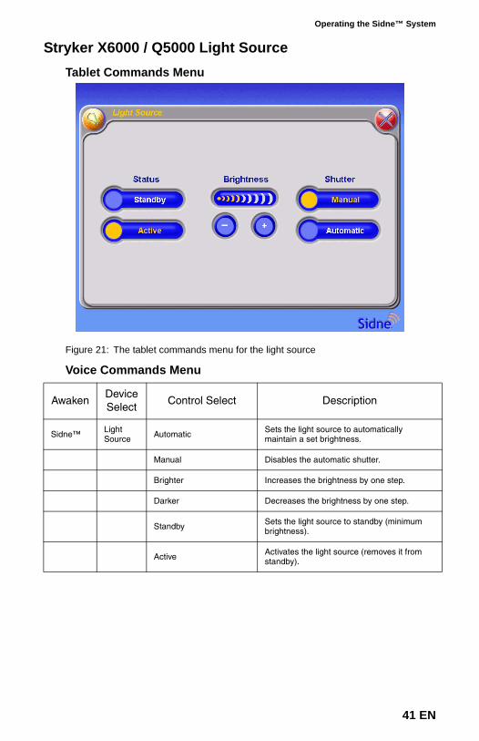
Stryker X6000 / Q5000 Light SourceTablet Commands Menu
Figure 21: The tablet commands menu for the light source
Voice Commands Menu
AwakenDevice Select
Control Select Description
Sidne™ Light Source Automatic Sets the light source to automatically
maintain a set brightness.
Manual Disables the automatic shutter.
Brighter Increases the brightness by one step.
Darker Decreases the brightness by one step.
Standby Sets the light source to standby (minimum brightness).
Active Activates the light source (removes it from standby).
41 EN
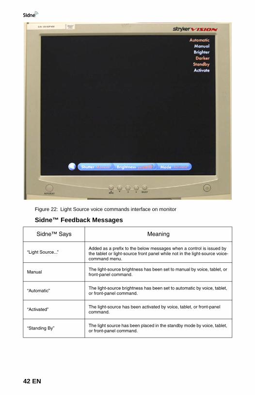
Figure 22: Light Source voice commands interface on monitor
Sidne™ Feedback Messages
Sidne™ Says Meaning
“Light Source...”Added as a prefix to the below messages when a control is issued by the tablet or light-source front panel while not in the light-source voice-command menu.
Manual The light-source brightness has been set to manual by voice, tablet, or front-panel command.
“Automatic” The light-source brightness has been set to automatic by voice, tablet, or front-panel command.
“Activated” The light-source has been activated by voice, tablet, or front-panel command.
“Standing By” The light source has been placed in the standby mode by voice, tablet, or front-panel command.
42 EN
Operating the Sidne™ System
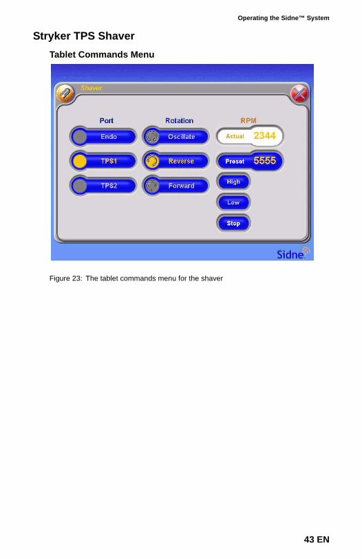
Stryker TPS ShaverTablet Commands Menu
Figure 23: The tablet commands menu for the shaver
43 EN
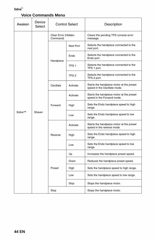
Voice Commands Menu
AwakenDevice Select
Control Select Description
Sidne™ Shaver
Clear Error (Hidden Command)
Clears the pending TPS console error message.
Handpiece
Next Port Selects the handpiece connected to the next port.
Endo Selects the handpiece connected to the Endo port.
TPS 1 Selects the handpiece connected to the TPS 1 port.
TPS 2 Selects the handpiece connected to the TPS 2 port.
Oscillate Activate Starts the handpiece motor at the preset speed in the Oscillate mode.
Forward
Activate Starts the handpiece motor at the preset speed in the Forward mode.
High Sets the Endo handpiece speed to high range.
Low Sets the Endo handpiece speed to low range.
Reverse
Activate Starts the handpiece motor at the preset speed in the reverse mode.
High Sets the Endo handpiece speed to high range.
Low Sets the Endo handpiece speed to low range.
Preset
Up Increases the handpiece preset speed.
Down Reduces the handpiece preset speed.
High Sets the handpiece speed to high range.
Low Sets the handpiece speed to low range.
Stop Stops the handpiece motor.
Stop Stops the handpiece motor.
44 EN
Operating the Sidne™ System
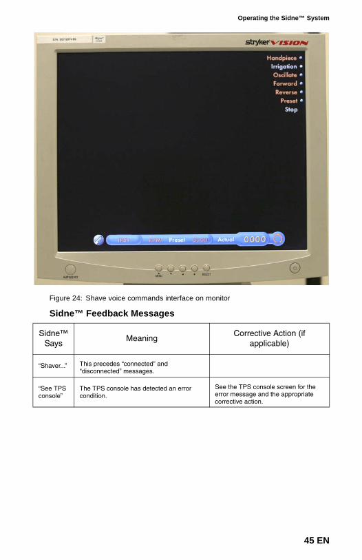
Figure 24: Shave voice commands interface on monitor
Sidne™ Feedback Messages
Sidne™ Says
MeaningCorrective Action (if
applicable)
“Shaver...” This precedes “connected” and “disconnected” messages.
“See TPS console”
The TPS console has detected an error condition.
See the TPS console screen for the error message and the appropriate corrective action.
45 EN
Stryker Digital Capture System (SDC Pro / SDC Pro 2 /SDC HD)
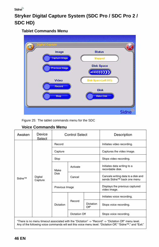
Tablet Commands Menu
Figure 25: The tablet commands menu for the SDC
Voice Commands Menu
Awaken Device Select
Control Select Description
Sidne™ Digital Capture
Record Initiates video recording.
Capture Captures the video image.
Stop Stops video recording.
Make Disk
Activate Initiates data writing to a recordable disk.
Cancel Cancels writing data to a disk and sends Sidne™ back one menu
Previous Image Displays the previous captured video image.
DictationRecord
Initiates voice recording.
Dictation Off*
Stops voice recording.
Dictation Off Stops voice recording.
*There is no menu timeout associated with the “Dictation” -> “Record” -> “Dictation Off” menu level. Any of the following voice commands will exit this voice menu level: “Dictation Off,” “Sidne™,” and “Exit.”
46 EN
Operating the Sidne™ System
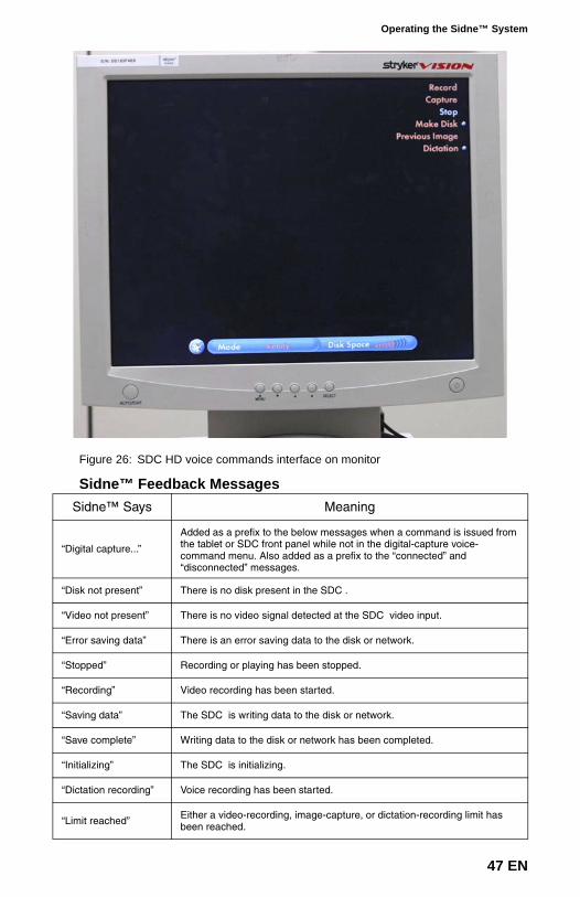
Figure 26: SDC HD voice commands interface on monitor
Sidne™ Feedback MessagesSidne™ Says Meaning
“Digital capture...”
Added as a prefix to the below messages when a command is issued from the tablet or SDC front panel while not in the digital-capture voice-command menu. Also added as a prefix to the “connected” and “disconnected” messages.
“Disk not present” There is no disk present in the SDC .
“Video not present” There is no video signal detected at the SDC video input.
“Error saving data” There is an error saving data to the disk or network.
“Stopped” Recording or playing has been stopped.
“Recording” Video recording has been started.
“Saving data” The SDC is writing data to the disk or network.
“Save complete” Writing data to the disk or network has been completed.
“Initializing” The SDC is initializing.
“Dictation recording” Voice recording has been started.
“Limit reached” Either a video-recording, image-capture, or dictation-recording limit has been reached.
47 EN
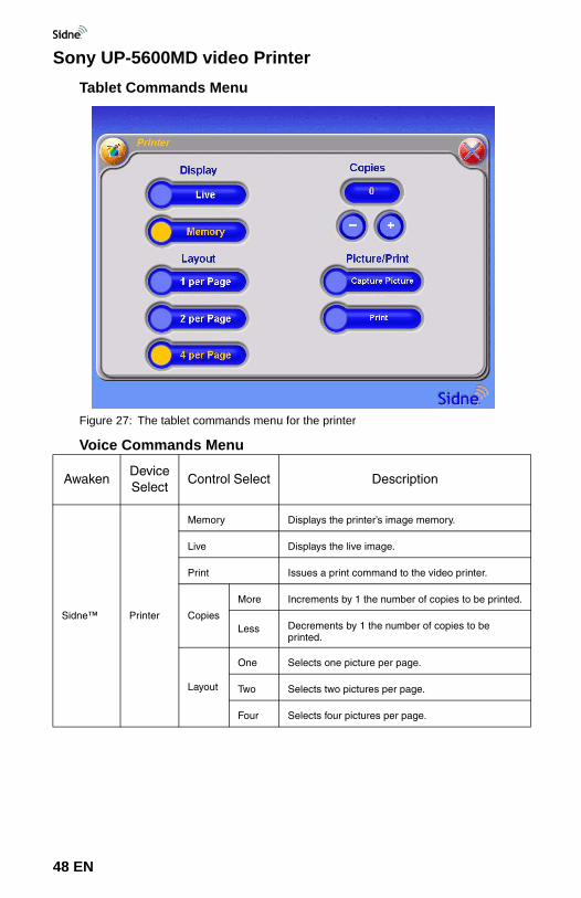
Sony UP-5600MD video PrinterTablet Commands Menu
Figure 27: The tablet commands menu for the printer
Voice Commands Menu
AwakenDevice Select
Control Select Description
Sidne™ Printer
Memory Displays the printer’s image memory.
Live Displays the live image.
Print Issues a print command to the video printer.
Copies
More Increments by 1 the number of copies to be printed.
Less Decrements by 1 the number of copies to be printed.
Layout
One Selects one picture per page.
Two Selects two pictures per page.
Four Selects four pictures per page.
48 EN
Operating the Sidne™ System
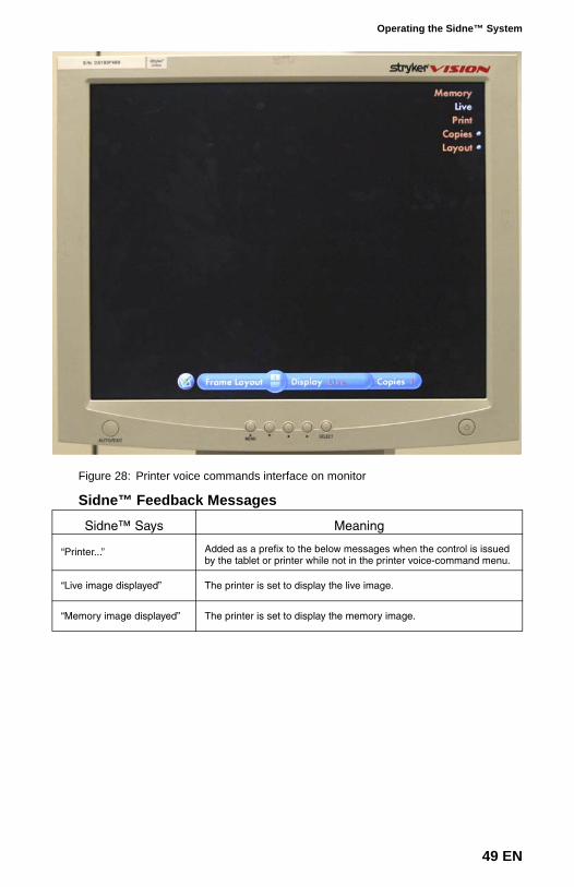
Figure 28: Printer voice commands interface on monitor
Sidne™ Feedback Messages
Sidne™ Says Meaning
“Printer...” Added as a prefix to the below messages when the control is issued by the tablet or printer while not in the printer voice-command menu.
“Live image displayed” The printer is set to display the live image.
“Memory image displayed” The printer is set to display the memory image.
49 EN
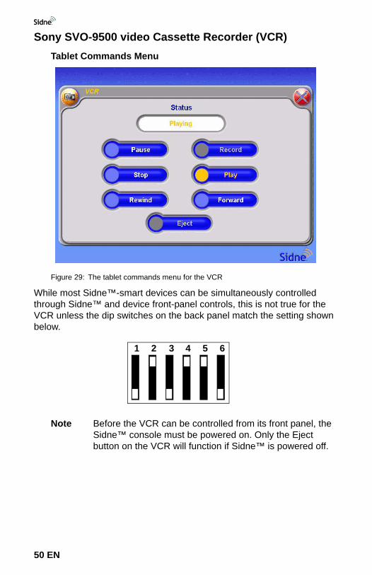
Sony SVO-9500 video Cassette Recorder (VCR)Tablet Commands Menu
Figure 29: The tablet commands menu for the VCR
While most Sidne™-smart devices can be simultaneously controlled through Sidne™ and device front-panel controls, this is not true for the VCR unless the dip switches on the back panel match the setting shown below.
Note Before the VCR can be controlled from its front panel, the Sidne™ console must be powered on. Only the Eject button on the VCR will function if Sidne™ is powered off.
21 3 4 5 6
50 EN
Operating the Sidne™ System
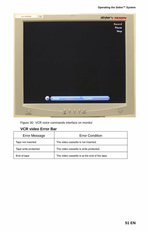
Figure 30: VCR voice commands interface on monitor
VCR video Error Bar
Error Message Error Condition
Tape not inserted The video cassette is not inserted.
Tape write protected The video cassette is write protected.
End of tape The video cassette is at the end of the tape.
51 EN
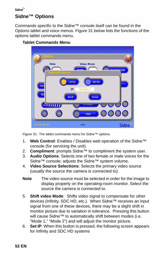
Sidne™ Options
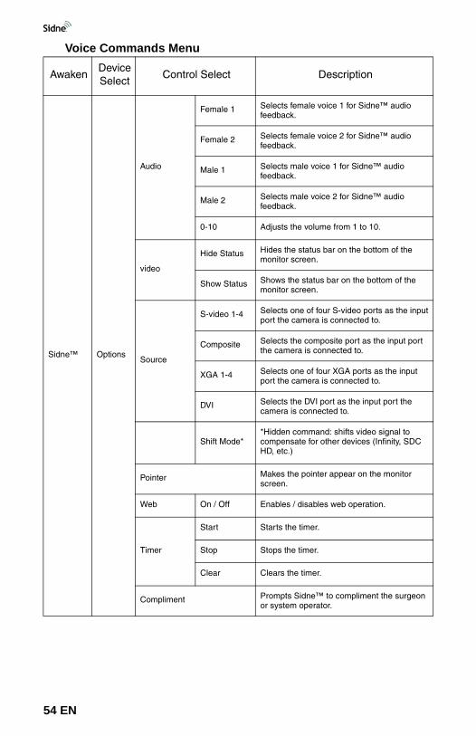
Commands specific to the Sidne™ console itself can be found in the Options tablet and voice menus. Figure 31 below lists the functions of the options tablet commands menu.
Tablet Commands Menu
Figure 31: The tablet commands menu for Sidne™ options.
1. Web Control: Enables / Disables web operation of the Sidne™ console (for servicing the unit).
2. Compliment: prompts Sidne™ to compliment the system user.3. Audio Options: Selects one of two female or male voices for the
Sidne™ console; adjusts the Sidne™ system volume.4. Video Source Selections: Selects the primary video source
(usually the source the camera is connected to).
Note The video source must be selected in order for the image to display properly on the operating-room monitor. Select the source the camera is connected to.
5. Shift video Mode: Shifts video signal to compensate for other devices (Infinity, SDC HD, etc.). When Sidne™ receives an input signal from one of these devices, there may be a slight shift in monitor picture due to variation in tolerance. Pressing this button will cause Sidne™ to automatically shift between modes (i.e. “Mode 1,” “Mode 2”) and will adjust the monitor picture.
6. Set IP: When this button is pressed, the following screen appears for Infinity and SDC HD systems
52 EN
Operating the Sidne™ System
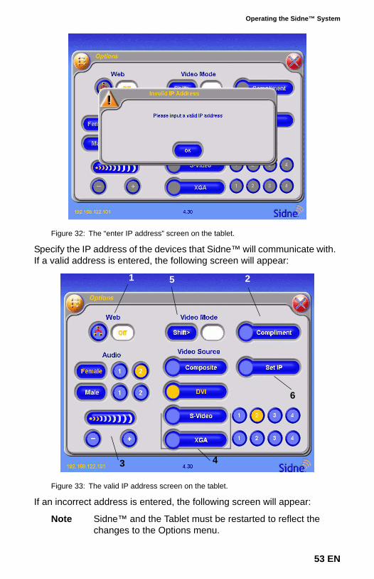
Figure 32: The “enter IP address” screen on the tablet.
Specify the IP address of the devices that Sidne™ will communicate with. If a valid address is entered, the following screen will appear:
Figure 33: The valid IP address screen on the tablet.
If an incorrect address is entered, the following screen will appear:
Note Sidne™ and the Tablet must be restarted to reflect the changes to the Options menu.
3
21
4
6
5
53 EN
Voice Commands Menu
AwakenDevice Select
Control Select Description
Sidne™ Options
Audio
Female 1 Selects female voice 1 for Sidne™ audio feedback.
Female 2 Selects female voice 2 for Sidne™ audio feedback.
Male 1 Selects male voice 1 for Sidne™ audio feedback.
Male 2 Selects male voice 2 for Sidne™ audio feedback.
0-10 Adjusts the volume from 1 to 10.
video
Hide Status Hides the status bar on the bottom of the monitor screen.
Show Status Shows the status bar on the bottom of the monitor screen.
Source
S-video 1-4 Selects one of four S-video ports as the input port the camera is connected to.
Composite Selects the composite port as the input port the camera is connected to.
XGA 1-4 Selects one of four XGA ports as the input port the camera is connected to.
DVI Selects the DVI port as the input port the camera is connected to.
Shift Mode**Hidden command: shifts video signal to compensate for other devices (Infinity, SDC HD, etc.)
Pointer Makes the pointer appear on the monitor screen.
Web On / Off Enables / disables web operation.
Timer
Start Starts the timer.
Stop Stops the timer.
Clear Clears the timer.
Compliment Prompts Sidne™ to compliment the surgeon or system operator.
54 EN
Operating the Sidne™ System
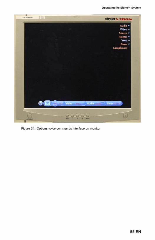
Figure 34: Options voice commands interface on monitor
55 EN
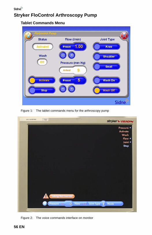
Stryker FloControl Arthroscopy PumpTablet Commands Menu
Figure 1: The tablet commands menu for the arthroscopy pump
Figure 2: The voice commands interface on monitor
56 EN
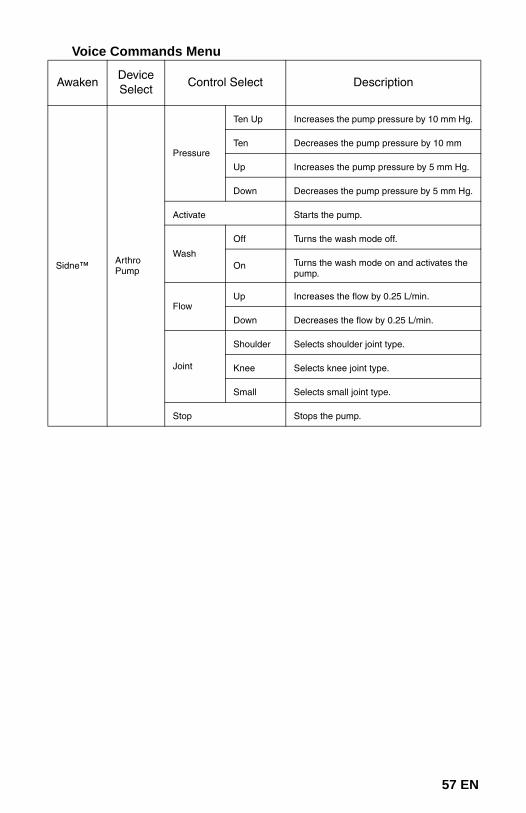
Voice Commands Menu
AwakenDevice Select
Control Select Description
Sidne™ Arthro Pump
Pressure
Ten Up Increases the pump pressure by 10 mm Hg.
Ten Decreases the pump pressure by 10 mm
Up Increases the pump pressure by 5 mm Hg.
Down Decreases the pump pressure by 5 mm Hg.
Activate Starts the pump.
Wash
Off Turns the wash mode off.
On Turns the wash mode on and activates the pump.
FlowUp Increases the flow by 0.25 L/min.
Down Decreases the flow by 0.25 L/min.
Joint
Shoulder Selects shoulder joint type.
Knee Selects knee joint type.
Small Selects small joint type.
Stop Stops the pump.
57 EN
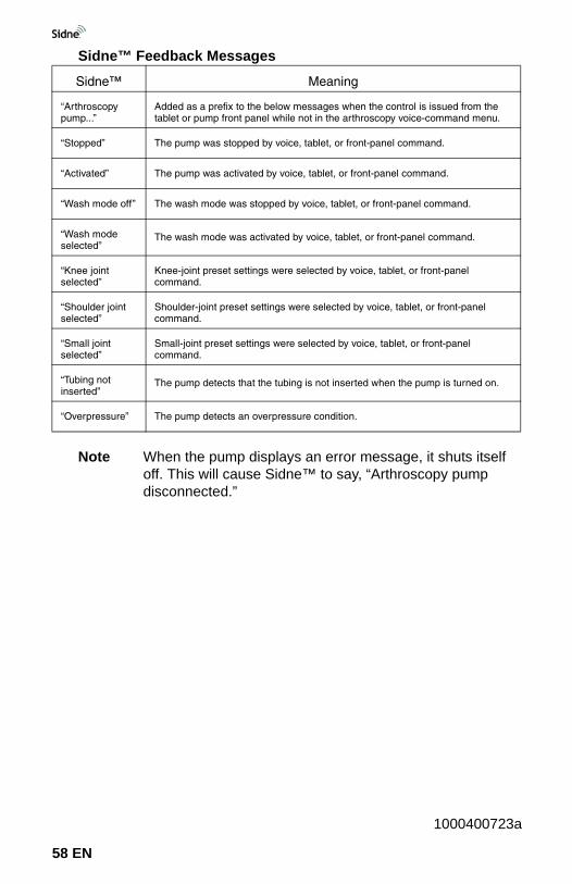
Sidne™ Feedback Messages
Note When the pump displays an error message, it shuts itself off. This will cause Sidne™ to say, “Arthroscopy pump disconnected.”
Sidne™ Meaning
“Arthroscopy pump...”
Added as a prefix to the below messages when the control is issued from the tablet or pump front panel while not in the arthroscopy voice-command menu.
“Stopped” The pump was stopped by voice, tablet, or front-panel command.
“Activated” The pump was activated by voice, tablet, or front-panel command.
“Wash mode off” The wash mode was stopped by voice, tablet, or front-panel command.
“Wash mode selected”
The wash mode was activated by voice, tablet, or front-panel command.
“Knee joint selected”
Knee-joint preset settings were selected by voice, tablet, or front-panel command.
“Shoulder joint selected”
Shoulder-joint preset settings were selected by voice, tablet, or front-panel command.
“Small joint selected”
Small-joint preset settings were selected by voice, tablet, or front-panel command.
“Tubing not inserted”
The pump detects that the tubing is not inserted when the pump is turned on.
“Overpressure” The pump detects an overpressure condition.
1000400723a
58 EN
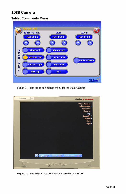
1088 Camera Tablet Commands Menu
Figure 1: The tablet commands menu for the 1088 Camera
Figure 2: The 1088 voice commands interface on monitor
59 EN
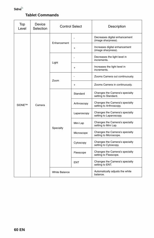
Tablet Commands
Top Level
Device Selection
Control Select Description
SIDNE™ Camera
Enhancement
- Decreases digital enhancement (image sharpness).
+ Increases digital enhancement (image sharpness).
Light
- Decreases the light level in increments.
+ Increases the light level in increments.
Zoom
- Zooms Camera out continuously.
+ Zooms Camera in continuously.
Specialty
Standard Changes the Camera’s specialty setting to Standard.
Arthroscopy Changes the Camera’s specialty setting to Arthroscopy.
Laparoscopy Changes the Camera’s specialty setting to Laparoscopy.
Mini Lap Changes the Camera’s specialty setting to Mini Lap.
Microscope Changes the Camera’s specialty setting to Microscope.
Cytoscopy Changes the Camera’s specialty setting to Cytoscopy.
Flexscope Changes the Camera’s specialty setting to Flexscope.
ENT Changes the Camera’s specialty setting to ENT.
White Balance Automatically adjusts the white balance.
60 EN
Voice Commands
Top Level
Device Selection
Control Select Description
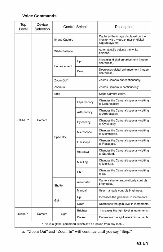
SIDNE™ Camera
Image Capture*Captures the image displayed on the monitor via a video printer or digital capture system.
White Balance Automatically adjusts the white balance.
Enhancement
Up Increases digital enhancement (image sharpness).
Down Decreases digital enhancement (image sharpness).
Zoom Outa
a. “Zoom Out” and “Zoom In” will continue until you say “Stop.”
Zooms Camera out continuously.
Zoom In Zooms Camera in continuously.
Stop Stops Camera zoom.
Specialty
Laparoscopy Changes the Camera’s specialty setting to Laparoscopy.
Arthroscopy Changes the Camera’s specialty setting to Arthroscopy.
Cytoscopy Changes the Camera’s specialty setting to Cytoscopy.
Microscope Changes the Camera’s specialty setting to Microscope.
Flexscope Changes the Camera’s specialty setting to Flexscope.
Standard Changes the Camera’s specialty setting to Standard.
Mini Lap Changes the Camera’s specialty setting to Mini Lap.
ENT Changes the Camera’s specialty setting to ENT.
ShutterAutomatic Camera shutter automatically controls
brightness.
Manual User manually controls brightness.
GainUp Increases the gain level in increments.
Down Decreases the gain level in increments.
Sidne™ Camera LightBrighter Increases the light level in increments.
Darker Decreases the light level in increments.
*This is a global command, which can be issued from any menu.
61 EN
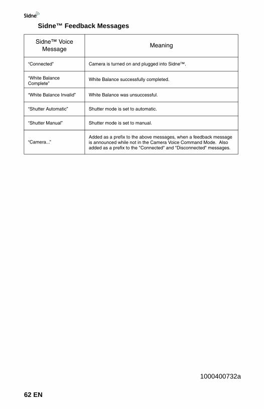
Sidne™ Feedback Messages
Sidne™ Voice Message
Meaning
“Connected” Camera is turned on and plugged into Sidne™.
“White Balance Complete”
White Balance successfully completed.
“White Balance Invalid” White Balance was unsuccessful.
“Shutter Automatic” Shutter mode is set to automatic.
“Shutter Manual” Shutter mode is set to manual.
“Camera...”Added as a prefix to the above messages, when a feedback message is announced while not in the Camera Voice Command Mode. Also added as a prefix to the "Connected" and "Disconnected" messages.
1000400732a
62 EN
SIDNE™ Cleaning and Maintenance
63 EN
CleaningWarning Unplug the Sidne™ console from the electrical outlet
before cleaning the unit.
Caution Do not immerse the console, tablet, or headset in any liquid, as product damage will result.
Caution Do not use solvents, such as alcohol, or cleaning solutions that contain ammonia to clean the console, tablet, or headset, as product damage may result.
Caution Do not sterilize the console, tablet, or headset, as product damage may result.
1. Wipe the console with a soft cloth dampened in a mild cleaning solution.
2. Clean the console with disinfectant if needed.3. Perform the same two steps for cleaning the tablet and headset.
MaintenanceThe Sidne™ system requires no preventative or periodic maintenance. The fuse on the console may be replaced at the hospital by a qualified technician.
Warning To reduce the risk of electrical shock, do not open the Sidne™ console, tablet, or headset. There are no user-serviceable components inside. Should service be needed, notify your local Stryker representative.
Replacing Fuses1. Unplug the Sidne™ console from the electrical outlet and
disconnect the power cord from the rear console panel.2. Unlatch the fuse holder next to the AC connection on the rear
console panel and remove the fuse. You may need to press the tab on the fuse holder with a slender screwdriver to release the latch.
3. Replace the fuse with a fuse of the same value and rating, pushing gently until the tab snaps in place.
Warning To avoid the risk of fire, use only replacement fuses specified in the Specifications section of this manual.
SIDNE™ Cleaning and Maintenance
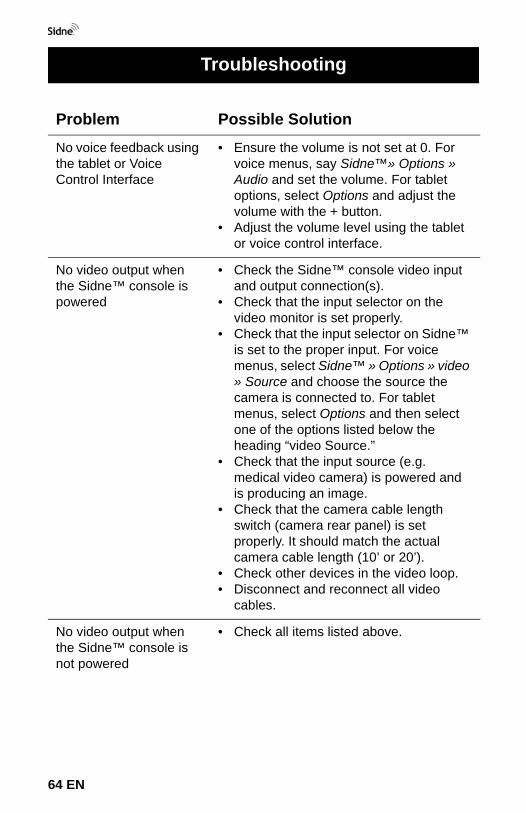
Problem Possible SolutionNo voice feedback using the tablet or Voice Control Interface
• Ensure the volume is not set at 0. For voice menus, say Sidne™» Options » Audio and set the volume. For tablet options, select Options and adjust the volume with the + button.
• Adjust the volume level using the tablet or voice control interface.
No video output when the Sidne™ console is powered
• Check the Sidne™ console video input and output connection(s).
• Check that the input selector on the video monitor is set properly.
• Check that the input selector on Sidne™ is set to the proper input. For voice menus, select Sidne™ » Options » video » Source and choose the source the camera is connected to. For tablet menus, select Options and then select one of the options listed below the heading “video Source.”
• Check that the input source (e.g. medical video camera) is powered and is producing an image.
• Check that the camera cable length switch (camera rear panel) is set properly. It should match the actual camera cable length (10’ or 20’).
• Check other devices in the video loop.• Disconnect and reconnect all video
cables.
No video output when the Sidne™ console is not powered
• Check all items listed above.
Troubleshooting
64 EN
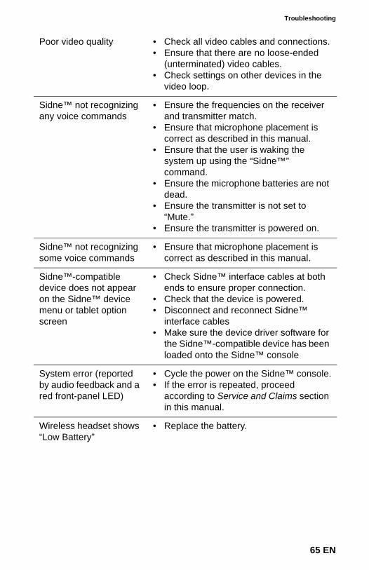
Troubleshooting
Poor video quality • Check all video cables and connections.• Ensure that there are no loose-ended
(unterminated) video cables.• Check settings on other devices in the
video loop.
Sidne™ not recognizing any voice commands
• Ensure the frequencies on the receiver and transmitter match.
• Ensure that microphone placement is correct as described in this manual.
• Ensure that the user is waking the system up using the “Sidne™” command.
• Ensure the microphone batteries are not dead.
• Ensure the transmitter is not set to “Mute.”
• Ensure the transmitter is powered on.
Sidne™ not recognizing some voice commands
• Ensure that microphone placement is correct as described in this manual.
Sidne™-compatible device does not appear on the Sidne™ device menu or tablet option screen
• Check Sidne™ interface cables at both ends to ensure proper connection.
• Check that the device is powered.• Disconnect and reconnect Sidne™
interface cables• Make sure the device driver software for
the Sidne™-compatible device has been loaded onto the Sidne™ console
System error (reported by audio feedback and a red front-panel LED)
• Cycle the power on the Sidne™ console.• If the error is repeated, proceed
according to Service and Claims section in this manual.
Wireless headset shows “Low Battery”
• Replace the battery.
65 EN
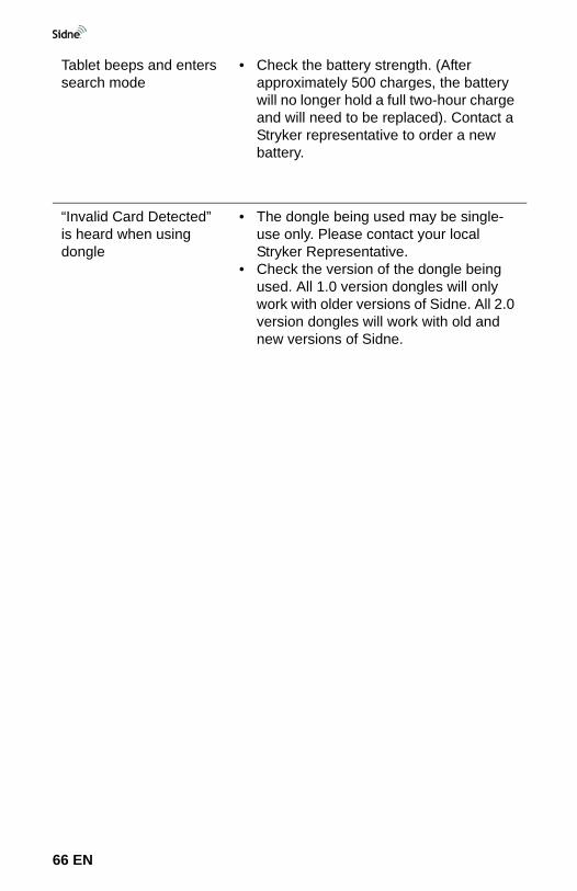
Tablet beeps and enters search mode
• Check the battery strength. (After approximately 500 charges, the battery will no longer hold a full two-hour charge and will need to be replaced). Contact a Stryker representative to order a new battery.
“Invalid Card Detected” is heard when using dongle
• The dongle being used may be single-use only. Please contact your local Stryker Representative.
• Check the version of the dongle being used. All 1.0 version dongles will only work with older versions of Sidne. All 2.0 version dongles will work with old and new versions of Sidne.
66 EN
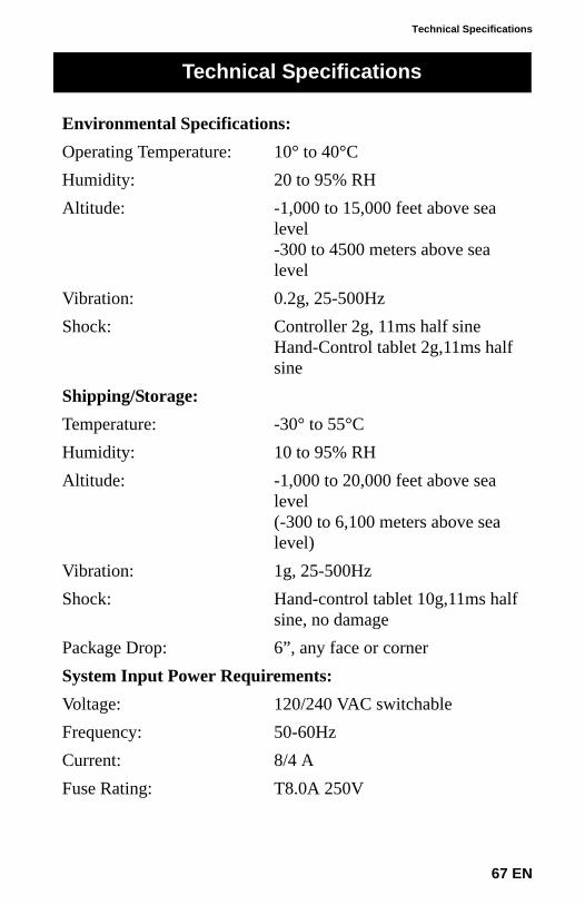
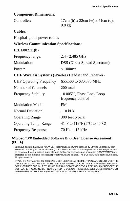
Technical Specifications
Environmental Specifications:Operating Temperature: 10° to 40°CHumidity: 20 to 95% RHAltitude: -1,000 to 15,000 feet above sea
level-300 to 4500 meters above sea level
Vibration: 0.2g, 25-500HzShock: Controller 2g, 11ms half sine
Hand-Control tablet 2g,11ms half sine
Shipping/Storage:Temperature: -30° to 55°CHumidity: 10 to 95% RHAltitude: -1,000 to 20,000 feet above sea
level (-300 to 6,100 meters above sea level)
Vibration: 1g, 25-500HzShock: Hand-control tablet 10g,11ms half
sine, no damagePackage Drop: 6”, any face or cornerSystem Input Power Requirements:Voltage: 120/240 VAC switchableFrequency: 50-60HzCurrent: 8/4 AFuse Rating: T8.0A 250V
Technical Specifications
67 EN
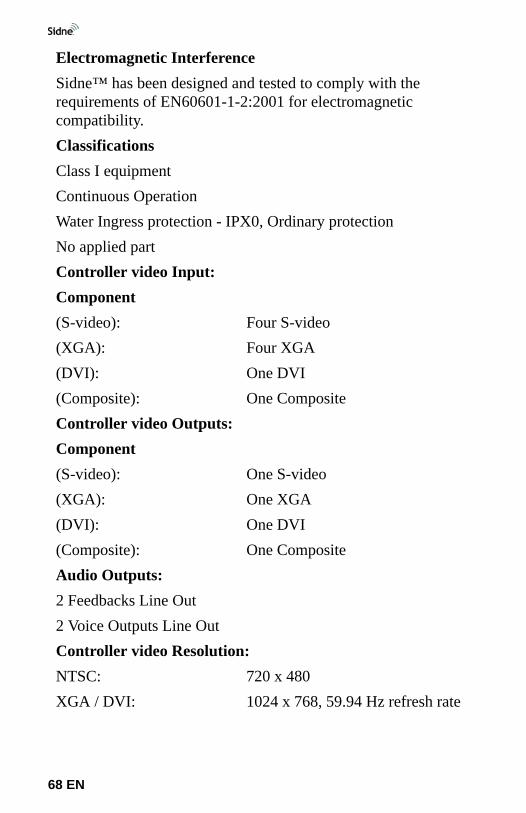
Electromagnetic InterferenceSidne™ has been designed and tested to comply with the requirements of EN60601-1-2:2001 for electromagnetic compatibility.ClassificationsClass I equipmentContinuous OperationWater Ingress protection - IPX0, Ordinary protectionNo applied partController video Input:Component(S-video): Four S-video(XGA): Four XGA(DVI): One DVI(Composite): One CompositeController video Outputs:Component(S-video): One S-video(XGA): One XGA(DVI): One DVI(Composite): One CompositeAudio Outputs:2 Feedbacks Line Out2 Voice Outputs Line OutController video Resolution:NTSC: 720 x 480XGA / DVI: 1024 x 768, 59.94 Hz refresh rate
68 EN
Technical Specifications
Microsoft XP Embedded Software End-User License Agreement (EULA)• You have acquired a device (“DEVICE”) that includes software licensed by Stryker Endoscopy from
Microsoft Licensing Inc. or its affiliates (“MS”). Those installed software products of MS origin, as well as associated media, printed materials, and “online” or electronic documentation (“SOFTWARE”) are protected by international intellectual property laws and treaties. The SOFTWARE is licensed, not sold. All rights reserved.
• IF YOU DO NOT AGREE TO THIS END USER LICENSE AGREEMENT (“EULA”), DO NOT USE THE DEVICE OR COPY THE SOFTWARE. INSTEAD, PROMPTLY CONTACT STRYKER ENDOSCOPY FOR INSTRUCTIONS ON RETURN OF THE UNUSED DEVICE FOR A REFUND. ANY USE OF THE SOFTWARE, INCLUDING BUT NOT LIMITED TO USE ON THE DEVICE, WILL CONSTITUTE YOUR AGREEMENT TO THIS EULA (OR RATIFICATION OF ANY PREVIOUS CONSENT).
Component Dimensions:Controller: 17cm (h) x 32cm (w) x 41cm (d);
9.8 kgCables:Hospital-grade power cablesWireless Communication Specifications:IEEE802.11(b)Frequency range: 2.4 - 2.485 GHzModulation: DSS (Direct Spread Spectrum)Power: < 100mwUHF Wireless Systems (Wireless Headset and Receiver)UHF Operating Frequency 655.500 to 680.375 MHzNumber of Channels 200 totalFrequency Stability ±0.005%, Phase Lock Loop
frequency controlModulation Mode FMNormal Deviation ±10 kHzOperating Range 300 feet typicalOperating Temp. Range 41°F to 113°F (5°C to 45°C)Frequency Response 70 Hz to 15 kHz
69 EN
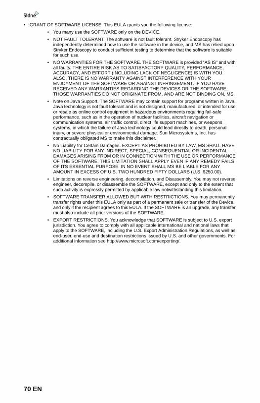
• GRANT OF SOFTWARE LICENSE. This EULA grants you the following license:• You many use the SOFTWARE only on the DEVICE.• NOT FAULT TOLERANT. The software is not fault tolerant. Stryker Endoscopy has
independently determined how to use the software in the device, and MS has relied upon Stryker Endoscopy to conduct sufficient testing to determine that the software is suitable for such use.
• NO WARRANTIES FOR THE SOFTWARE. THE SOFTWARE is provided “AS IS” and with all faults. THE ENTIRE RISK AS TO SATISFACTORY QUALITY, PERFORMANCE, ACCURACY, AND EFFORT (INCLUDING LACK OF NEGLIGENCE) IS WITH YOU. ALSO, THERE IS NO WARRANTY AGAINST INTERFERENCE WITH YOUR ENJOYMENT OF THE SOFTWARE OR AGAINST INFRINGEMENT. IF YOU HAVE RECEIVED ANY WARRANTIES REGARDING THE DEVICES OR THE SOFTWARE, THOSE WARRANTIES DO NOT ORIGINATE FROM, AND ARE NOT BINDING ON, MS.
• Note on Java Support. The SOFTWARE may contain support for programs written in Java. Java technology is not fault tolerant and is not designed, manufactured, or intended for use or resale as online control equipment in hazardous environments requiring fail-safe performance, such as in the operation of nuclear facilities, aircraft navigation or communication systems, air traffic control, direct life support machines, or weapons systems, in which the failure of Java technology could lead directly to death, personal injury, or severe physical or environmental damage. Sun Microsystems, Inc. has contractually obligated MS to make this disclaimer.
• No Liability for Certain Damages. EXCEPT AS PROHIBITED BY LAW, MS SHALL HAVE NO LIABILITY FOR ANY INDIRECT, SPECIAL, CONSEQUENTIAL OR INCIDENTAL DAMAGES ARISING FROM OR IN CONNECTION WITH THE USE OR PERFORMANCE OF THE SOFTWARE. THIS LIMITATION SHALL APPLY EVEN IF ANY REMEDY FAILS OF ITS ESSENTIAL PURPOSE. IN NO EVENT SHALL MS BE LIABLE FOR ANY AMOUNT IN EXCESS OF U.S. TWO HUNDRED FIFTY DOLLARS (U.S. $250.00).
• Limitations on reverse engineering, decompilation, and Disassembly. You may not reverse engineer, decompile, or disassemble the SOFTWARE, except and only to the extent that such activity is expressly permitted by applicable law notwithstanding this limitation.
• SOFTWARE TRANSFER ALLOWED BUT WITH RESTRICTIONS. You may permanently transfer rights under this EULA only as part of a permanent sale or transfer of the Device, and only if the recipient agrees to this EULA. If the SOFTWARE is an upgrade, any transfer must also include all prior versions of the SOFTWARE.
• EXPORT RESTRICTIONS. You acknowledge that SOFTWARE is subject to U.S. export jurisdiction. You agree to comply with all applicable international and national laws that apply to the SOFTWARE, including the U.S. Export Administration Regulations, as well as end-user, end-use and destination restrictions issued by U.S. and other governments. For additional information see http://www.microsoft.com/exporting/.
70 EN

Electromagnetic Compatibility Tables
Like other electrical medical equipment, Sidne™ requires special precautions to ensure electromagnetic compatibility with other electrical medical devices. To ensure electromagnetic compatibility (EMC), Sidne™ must be installed and operated according to the EMC information provided in this manual.
Warning The radiated output power of Sidne™ is below the FCC radio frequency exposure limits. Nevertheless, the device should be used in such a manner that the potential for human contact with the antenna during normal operation is minimized. In order to avoid the possibility of exceeding the FCC radio frequency exposure limits, human proximity to the antenna should be more than 20cm during normal operation.
Warning Do not use cables or accessories other than those provided with Sidne™, as this may result in increased electromagnetic emissions or decreased immunity to such emissions.
Warning If Sidne™ is used adjacent to or stacked with other equipment, verify normal operation of Sidne™ in the configuration in which it will be used prior to using it in a surgical procedure. Perform the steps in the section “Testing Compatibility” below to ensure electro-magnetic compatibility among operating room devices.
Caution Portable and mobile RF communications equipment may affect the normal function of Sidne™.
Caution To prevent radio interference with any licensed service, Sidne™ is intended to be operated indoors and away from windows to provide maximum shielding.
Caution Any changes or modifications not explicitly approved by Stryker Endoscopy could cause Sidne™ to cease to comply with FCC rules, and thus void the user’s authority to operate the equipment.
Electromagnetic Compatibility Tables
71 EN
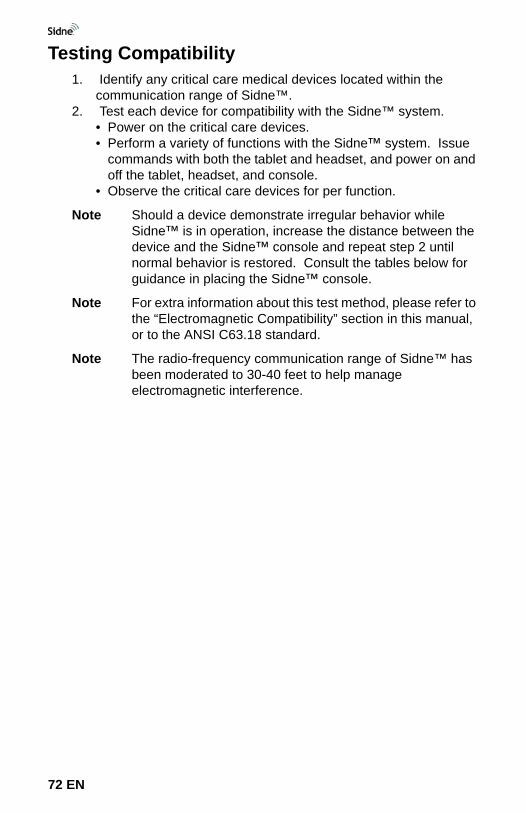
Testing Compatibility1. Identify any critical care medical devices located within the
communication range of Sidne™.2. Test each device for compatibility with the Sidne™ system.
• Power on the critical care devices.• Perform a variety of functions with the Sidne™ system. Issue
commands with both the tablet and headset, and power on and off the tablet, headset, and console.
• Observe the critical care devices for per function.
Note Should a device demonstrate irregular behavior while Sidne™ is in operation, increase the distance between the device and the Sidne™ console and repeat step 2 until normal behavior is restored. Consult the tables below for guidance in placing the Sidne™ console.
Note For extra information about this test method, please refer to the “Electromagnetic Compatibility” section in this manual, or to the ANSI C63.18 standard.
Note The radio-frequency communication range of Sidne™ has been moderated to 30-40 feet to help manage electromagnetic interference.
72 EN
Electromagnetic Compatibility Tables
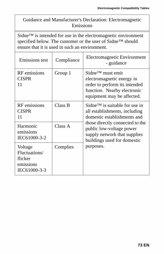
Guidance and Manufacturer's Declaration: Electromagnetic Emissions
Sidne™ is intended for use in the electromagnetic environment specified below. The customer or the user of Sidne™ should ensure that it is used in such an environment.
Emissions test Compliance Electromagnetic Environment - guidance
RF emissions CISPR11
Group 1 Sidne™ must emit electromagnetic energy in order to perform its intended function. Nearby electronic equipment may be affected.
RF emissions CISPR11
Class B Sidne™ is suitable for use in all establishments, including domestic establishments and those directly connected to the public low-voltage power supply network that supplies buildings used for domestic purposes.
Harmonic emissionsIEC61000-3-2
Class A
Voltage Fluctuations/flicker emissionsIEC61000-3-3
Complies
73 EN
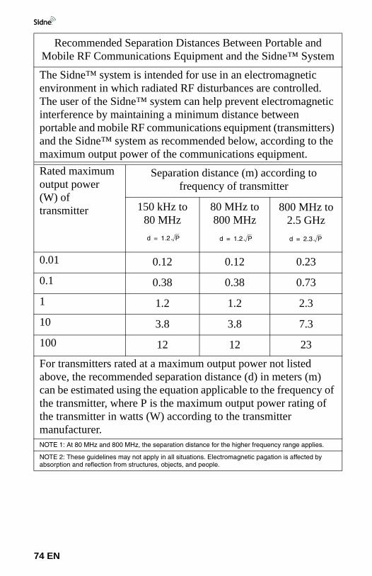
Recommended Separation Distances Between Portable and Mobile RF Communications Equipment and the Sidne™ System
The Sidne™ system is intended for use in an electromagnetic environment in which radiated RF disturbances are controlled. The user of the Sidne™ system can help prevent electromagnetic interference by maintaining a minimum distance between portable and mobile RF communications equipment (transmitters) and the Sidne™ system as recommended below, according to the maximum output power of the communications equipment.Rated maximum output power (W) of transmitter
Separation distance (m) according to frequency of transmitter
150 kHz to 80 MHz
80 MHz to 800 MHz
800 MHz to 2.5 GHz
0.01 0.12 0.12 0.23
0.1 0.38 0.38 0.73
1 1.2 1.2 2.3
10 3.8 3.8 7.3
100 12 12 23
For transmitters rated at a maximum output power not listed above, the recommended separation distance (d) in meters (m) can be estimated using the equation applicable to the frequency of the transmitter, where P is the maximum output power rating of the transmitter in watts (W) according to the transmitter manufacturer.NOTE 1: At 80 MHz and 800 MHz, the separation distance for the higher frequency range applies.
NOTE 2: These guidelines may not apply in all situations. Electromagnetic pagation is affected by absorption and reflection from structures, objects, and people.
d 1.2 P= d 1.2 P= d 2.3 P=
74 EN
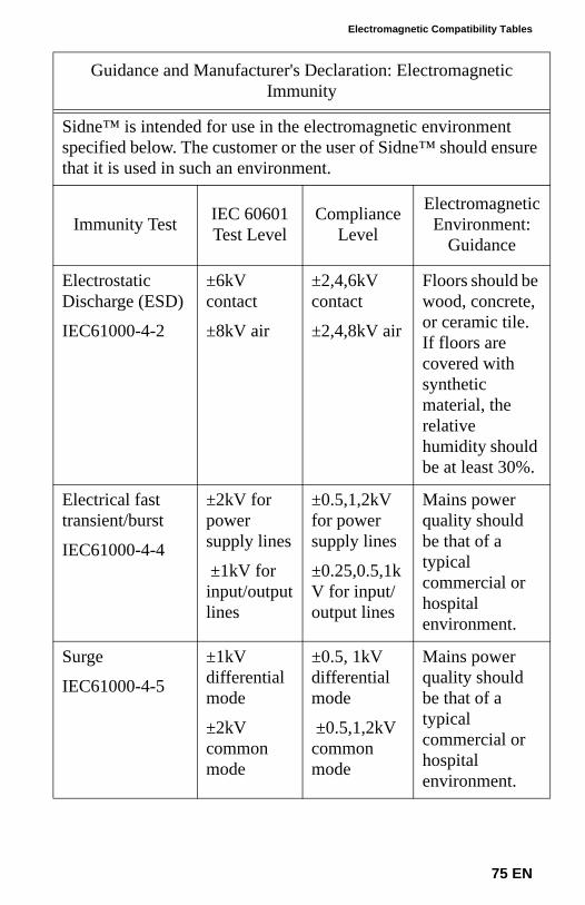
Electromagnetic Compatibility Tables
Guidance and Manufacturer's Declaration: Electromagnetic Immunity
Sidne™ is intended for use in the electromagnetic environment specified below. The customer or the user of Sidne™ should ensure that it is used in such an environment.
Immunity Test IEC 60601 Test Level
Compliance Level
Electromagnetic Environment:
Guidance
Electrostatic Discharge (ESD)
IEC61000-4-2
±6kV contact
±8kV air
±2,4,6kV contact
±2,4,8kV air
Floors should be wood, concrete, or ceramic tile. If floors are covered with synthetic material, the relative humidity should be at least 30%.
Electrical fast transient/burst
IEC61000-4-4
±2kV for power supply lines
±1kV for input/output lines
±0.5,1,2kV for power supply lines
±0.25,0.5,1kV for input/output lines
Mains power quality should be that of a typical commercial or hospital environment.
Surge
IEC61000-4-5
±1kV differential mode
±2kV common mode
±0.5, 1kV differential mode
±0.5,1,2kV common mode
Mains power quality should be that of a typical commercial or hospital environment.
75 EN
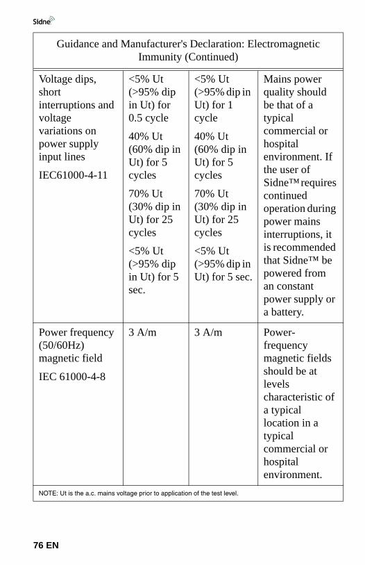
Voltage dips, short interruptions and voltage variations on power supply input lines
IEC61000-4-11
<5% Ut (>95% dip in Ut) for 0.5 cycle
40% Ut (60% dip in Ut) for 5 cycles
70% Ut (30% dip in Ut) for 25 cycles
<5% Ut (>95% dip in Ut) for 5 sec.
<5% Ut (>95% dip in Ut) for 1 cycle
40% Ut (60% dip in Ut) for 5 cycles
70% Ut (30% dip in Ut) for 25 cycles
<5% Ut (>95% dip in Ut) for 5 sec.
Mains power quality should be that of a typical commercial or hospital environment. If the user of Sidne™ requires continued operation during power mains interruptions, it is recommended that Sidne™ be powered from an constant power supply or a battery.
Power frequency (50/60Hz) magnetic field
IEC 61000-4-8
3 A/m 3 A/m Power-frequency magnetic fields should be at levels characteristic of a typical location in a typical commercial or hospital environment.
NOTE: Ut is the a.c. mains voltage prior to application of the test level.
Guidance and Manufacturer's Declaration: Electromagnetic Immunity (Continued)
76 EN
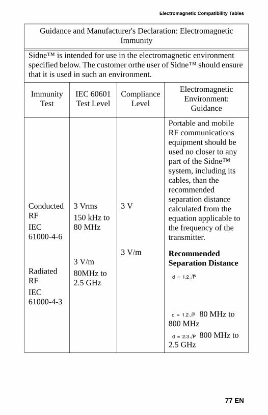
Electromagnetic Compatibility Tables
Guidance and Manufacturer's Declaration: Electromagnetic Immunity
Sidne™ is intended for use in the electromagnetic environment specified below. The customer orthe user of Sidne™ should ensure that it is used in such an environment.
Immunity Test
IEC 60601 Test Level
Compliance Level
Electromagnetic Environment:
Guidance
Conducted RFIEC 61000-4-6
Radiated RFIEC 61000-4-3
3 Vrms150 kHz to 80 MHz
3 V/m80MHz to 2.5 GHz
3 V
3 V/m
Portable and mobile RF communications equipment should be used no closer to any part of the Sidne™ system, including its cables, than the recommended separation distance calculated from the equation applicable to the frequency of the transmitter.
Recommended Separation Distance
80 MHz to 800 MHz
800 MHz to 2.5 GHz
d 1.2 P=
d 1.2 P=
d 2.3 P=
77 EN
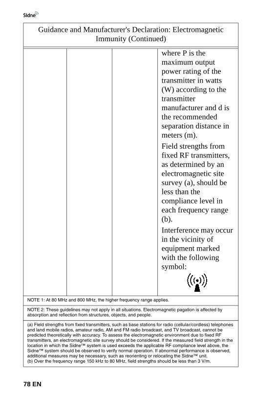
where P is the maximum output power rating of the transmitter in watts (W) according to the transmitter manufacturer and d is the recommended separation distance in meters (m).Field strengths from fixed RF transmitters, as determined by an electromagnetic site survey (a), should be less than the compliance level in each frequency range (b).Interference may occur in the vicinity of equipment marked with the following symbol:
NOTE 1: At 80 MHz and 800 MHz, the higher frequency range applies.
NOTE 2: These guidelines may not apply in all situations. Electromagnetic pagation is affected by absorption and reflection from structures, objects, and people.
(a) Field strengths from fixed transmitters, such as base stations for radio (cellular/cordless) telephones and land mobile radios, amateur radio, AM and FM radio broadcast, and TV broadcast, cannot be predicted theoretically with accuracy. To assess the electromagnetic environment due to fixed RF transmitters, an electromagnetic site survey should be considered. If the measured field strength in the location in which the Sidne™ system is used exceeds the applicable RF compliance level above, the Sidne™ system should be observed to verify normal operation. If abnormal performance is observed, additional measures may be necessary, such as reorienting or relocating the Sidne™ unit.(b) Over the frequency range 150 kHz to 80 MHz, field strengths should be less than 3 V/m.
Guidance and Manufacturer's Declaration: Electromagnetic Immunity (Continued)
78 EN
Warranty
79 EN
The warranty set forth herein is exclusive and in lieu of all other warranties, remedies, obligations, and liabilities of Stryker Endoscopy, expressed or implied, including the implied warranties of merchantability and fitness for use and of consequential damages.
This product is being sold only for the purpose described herein. In no event shall Stryker Endoscopy be liable for any breach of warranty in any amount exceeding the purchase price of the product.
Stryker Endoscopy warrants this product against defects in both materials and workmanship to the registered owner at the time of purchase. This warranty is valid only to the original purchaser of Stryker Endoscopy products directly from a Stryker Endoscopy authorized agent. The warranty cannot be transferred or assigned by the original purchaser.
The purchaser is responsible for returning defective equipment to the factory at his or her own expense. Stryker Endoscopy or its representative will service the equipment, repair or replace any defective parts thereof, and return it to the purchaser.
This warranty does not apply to any product that has been subject to misuse, neglect, or improper installation, or has been altered, adjusted, or tampered with by any person other than Stryker Endoscopy authorized personnel. If, upon examination by authorized service personnel, it is determined that the malfunction is due to misuse or abuse, warranty provisions will not apply. An estimate of the cost of repair work will be given to the purchaser prior to servicing and repairing the product.
Products repaired under Stryker Endoscopy’s standard repair program will be issued a thirty-day warranty against defects in both materials and workmanship, provided the original warranty period has passed. Products submitted due to defects in materials and workmanship during the warranty period will be repaired at no charge to the purchaser.
No agent, employee, or representative of Stryker Endoscopy has the authority to bind the Company to any other warranty, affirmation, or representation concerning this product.
All components are covered by warranty for one year as described above.
Note This warranty applies to customers in the United States only. Outside of the U.S.A, contact your Stryker sales representative or your local Stryker subsidiary.
Warranty
80 EN
If service is needed either during or after the warranty period:
1. Contact Stryker Endoscopy at 1-800-642-4422 or phone your local Stryker Endoscopy sales representative.
2. When returning equipment for service, package all the components carefully in the original shipping container, if possible.
3. Ship the Sidne™ unit, prepaid and insured, to your local Stryker Endoscopy distributor or to:
Stryker Endoscopy Customer ServiceAttention: Repair Department5900 Optical CourtSan Jose, CA 95138 USA
Note The device described in this manual is continually being reviewed, and improvements may be made without notice.
Stryker is a registered trademark of Stryker Corporation.
Service and Claims

International Service
For service in the U.S.A., call your Stryker Endoscopy representative or Stryker Endoscopy Customer Service at 1-800-624-4422. Outside of the U.S.A., please contact your Stryker Endoscopy distributor at one of the following locations:
Stryker Corporation2725 Fairfield RoadKalamazoo, MI 49002USAPhone: 1-269-385-2600Telex: 224464 STRYKER KMZFax: 1-269-385-1996
Stryker European Rep - RA/QA ManagerZAC Satolas Green PusignanAv. de Satolas Green69881 MEYZIEU Cedex, FRANCEPhone: 33-1-48175000Fax: 33-1-48632175
Stryker Canada45 Innovation Drive Hamilton, Ontario, CANADA L9H 7L8 Phone: (905) 690-5700(800) 668-8323 (toll free) Fax: +1(905) 690-5698
Stryker India Private LimitedFirst Floor C-5, SDA Commercial ComplexNew Delhi 110 017INDIAPhone: 91-11-686-6740Fax: 91-11-696-6020
Stryker Deutschland GmbHGewerbeallee 18, D-45478Mulheim an der RuhrGERMANYPhone: 49-208-999-060Fax: 49-208-999-0666
Stryker AustraliaUnit 58, 2a Herbert St.St. Leonards, NSW 2065AUSTRALIAPhone: 02-9467-1000Fax: 02-9467-1010
Stryker Latin America15100 N.W. 67th Ave. Suite 210Miami, Florida 33014USAPhone: 1-305-821-1888Fax: 1-305-826-0067
Stryker Singapore PTE/LTD70 Bendemeer Road#03-32 Hiap Huat HouseSINGAPORE 339940Phone: 65-293-0119Fax: 65-293-7028
Stryker B.V.Marinus van Meelweg 17P.O. Box 87475657 En EindhovenTHE NETHERLANDSPhone: 31-40-2922522Fax: 31-40-2922555
Stryker Pacific Ltd.Suite 2501, Citibank TowerCitibank Plaza3 Garden Road, CentralHONG KONGPhone: 61-2-9415-5100Fax: 61-29-4294127
Stryker Osteonics, SA5, Chemin des Aulx 51228 Plan-les-OuatesCase Postale 7251212 Grand-Lancy 1Geneve, SWITZERLANDPhone: 41-22-884-0111Fax: 41-22-884-0199
Stryker Mexico, S.A. de C.V.Calle Sacramento 410Col. Insurgentes San BorjaC.P. 03100Mexico, D.F.MEXICO Phone: 525-488-0890Fax: 525-488-0891
International Service
81 EN
Stryker FinlandPL 80 (Makelankatuz)FIN 00501 HelsinkiFINLANDPhone: 358 (0) 9 7744 680Fax: 358 (0) 9 7744 6820
Stryker Middle East / AfricaVia Della Posta6934 BioggioSWITZERLANDPhone: (4021) 212-1122Fax: (4021) 212-1133
Stryker Korea11F Dong Sung Bldg. 154-24 Samsung-dongKangnam-kuSeoul, KOREA 135-090Phone: 82-2-34517572Fax: 82-2-552-4156
NV Stryker SA (Belgium)Ikaros Business Park Fase IIIIkaroslaan 12 1930 ZaventemBrussels, BELGIUMPhone: 32-2-717-92-10Fax: 32-2-717-92-49
Stryker China LimitedRoom 903-905, Office Tower 2Beijing Sun Dong An Plaza138 Wang Fu Jing Da JieBeijing 100006, P.R.CHINAPhone: 86-10-65136183Fax: 86-10-83913571
Stryker ChileAvenida Nueva Tajamar 481Oficina 805 Piso 8 Torre Norte Santiago, CHILEPhone: 562-244-3600Fax: 562-244-3696
Stryker JapanDai Tokyo Kasai Shinjuku Bldg.3-25-3, YoyogiShibuya-ku, Tokyo 151-0053JAPANPhone: 813-535-29106Fax: 813-535-21789
Stryker SpainManuel Tovar 3528034 MadridSPAINPhone: 34-91-7283500Fax: 34-91-3580748
Stryker Europe HeadquartersCite-Centre, Grand Rue 92CH-1820 MontreuxSWITZERLANDPhone: 41-21-966-1201Fax: 41-21-966-1200
Stryker AB ScandinaviaKrossverksgatan 3S-216 10 MalmöSWEDENPhone: 46 40-69-18-100Fax: 46 40-69-18-190
Stryker Taiwan5F-1,23 Pa Te RoadSection 1, Taipei, TAIWAN, R.O.C.Phone: 886-2-2322-2895Fax: 886-2-2357-8543
Stryker AB DenmarkSankt Annae Plads 91021 Copenhagen, DENMARKPhone: 45 33 9360 99Fax: 45 33 9320 69
Stryker U.K. Ltd.Hambridge RoadNewburyBerkshire RG14 5 EPUNITED KINGDOMPhone: 44-1635-262400Fax: 44-1635-262464
MANUFACTURERStryker Endoscopy Inc.5900 Optical CourtSan Jose, CA 95138USAPhone: 408-754-2000Fax: 408-754-2505
82 EN
Addenda to the Sidne Manual
83 EN
Installing the Telephone Upgrade . . . . . . . . . . . . . 83 ENSidne™ Operating and Maintenance Manual Addendum . . . . . . . . . . . . . . . . . . . . . . . . . . . . . . . . 90 ENInstalling the Tablet Battery Pack . . . . . . . . . . . . 113 ENSidne™ Tablet-Recharging Cradle. . . . . . . . . . . . 114 EN
All of these addenda are commercially available to users. Please contact your local Stryker Representative for ordering information.
Addenda to the Sidne Manual
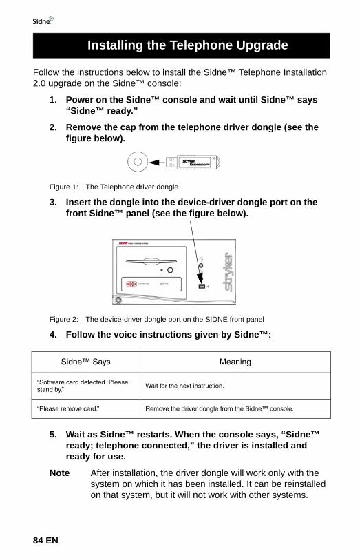
Follow the instructions below to install the Sidne™ Telephone Installation 2.0 upgrade on the Sidne™ console:
1. Power on the Sidne™ console and wait until Sidne™ says “Sidne™ ready.”
2. Remove the cap from the telephone driver dongle (see the figure below).
Figure 1: The Telephone driver dongle
3. Insert the dongle into the device-driver dongle port on the front Sidne™ panel (see the figure below).
Figure 2: The device-driver dongle port on the SIDNE front panel
4. Follow the voice instructions given by Sidne™:
5. Wait as Sidne™ restarts. When the console says, “Sidne™ ready; telephone connected,” the driver is installed and ready for use.
Note After installation, the driver dongle will work only with the system on which it has been installed. It can be reinstalled on that system, but it will not work with other systems.
Sidne™ Says Meaning
“Software card detected. Please stand by.” Wait for the next instruction.
“Please remove card.” Remove the driver dongle from the Sidne™ console.
Installing the Telephone Upgrade
84 EN
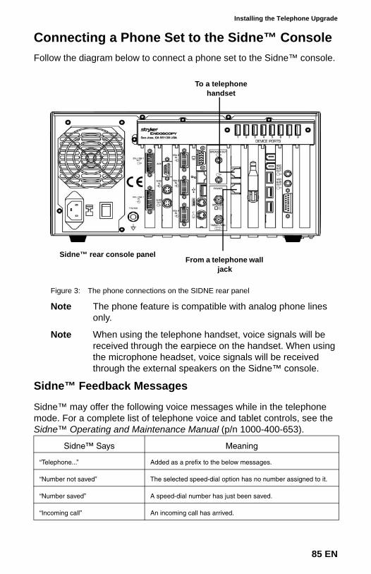
Installing the Telephone Upgrade
Connecting a Phone Set to the Sidne™ ConsoleFollow the diagram below to connect a phone set to the Sidne™ console.
Figure 3: The phone connections on the SIDNE rear panel
Note The phone feature is compatible with analog phone lines only.
Note When using the telephone handset, voice signals will be received through the earpiece on the handset. When using the microphone headset, voice signals will be received through the external speakers on the Sidne™ console.
Sidne™ Feedback Messages
Sidne™ may offer the following voice messages while in the telephone mode. For a complete list of telephone voice and tablet controls, see the Sidne™ Operating and Maintenance Manual (p/n 1000-400-653).
Sidne™ Says Meaning
“Telephone...” Added as a prefix to the below messages.
“Number not saved” The selected speed-dial option has no number assigned to it.
“Number saved” A speed-dial number has just been saved.
“Incoming call” An incoming call has arrived.
To a telephone handset
From a telephone wall jack
Sidne™ rear console panel
85 EN
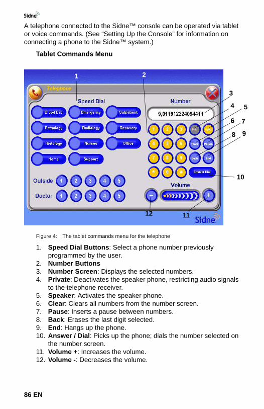
A telephone connected to the Sidne™ console can be operated via tablet or voice commands. (See “Setting Up the Console” for information on connecting a phone to the Sidne™ system.)
Tablet Commands Menu
Figure 4: The tablet commands menu for the telephone
1. Speed Dial Buttons: Select a phone number previously programmed by the user.
2. Number Buttons3. Number Screen: Displays the selected numbers.4. Private: Deactivates the speaker phone, restricting audio signals
to the telephone receiver.5. Speaker: Activates the speaker phone.6. Clear: Clears all numbers from the number screen.7. Pause: Inserts a pause between numbers.8. Back: Erases the last digit selected.9. End: Hangs up the phone.10. Answer / Dial: Picks up the phone; dials the number selected on
the number screen.11. Volume +: Increases the volume.12. Volume -: Decreases the volume.
2
6
1112
1
3
4 5
7
8 9
10
86 EN
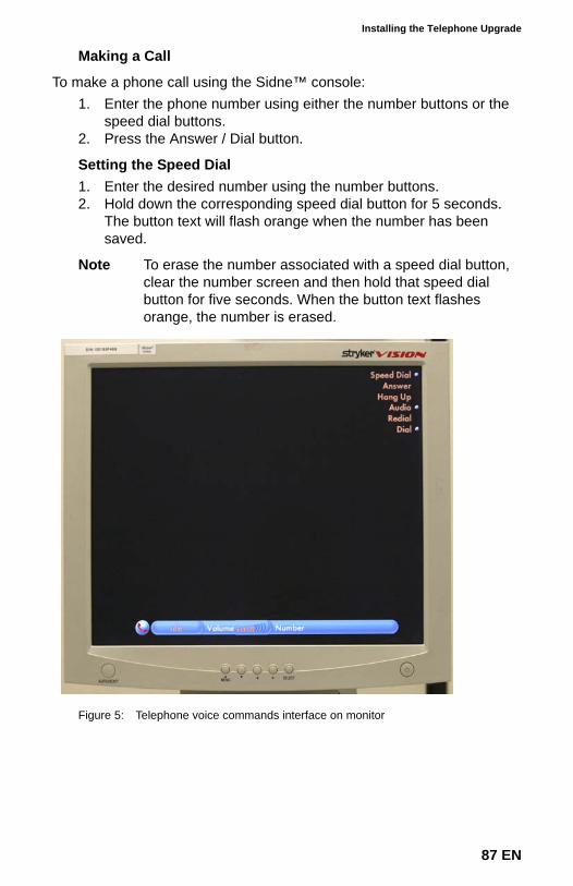
Installing the Telephone Upgrade
Making a Call
To make a phone call using the Sidne™ console:1. Enter the phone number using either the number buttons or the
speed dial buttons.2. Press the Answer / Dial button.
Setting the Speed Dial 1. Enter the desired number using the number buttons.2. Hold down the corresponding speed dial button for 5 seconds.
The button text will flash orange when the number has been saved.
Note To erase the number associated with a speed dial button, clear the number screen and then hold that speed dial button for five seconds. When the button text flashes orange, the number is erased.
Figure 5: Telephone voice commands interface on monitor
87 EN
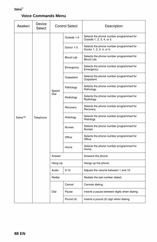
Voice Commands Menu
AwakenDevice Select
Control Select Description
Sidne™ Telephone
Speed Dial
Outside 1-5 Selects the phone number programmed for Outside 1, 2, 3, 4, or 5.
Doctor 1-5 Selects the phone number programmed for Doctor 1, 2, 3, 4, or 5.
Blood Lab Selects the phone number programmed for Blood Lab.
Emergency Selects the phone number programmed for Emergency.
Outpatient Selects the phone number programmed for Outpatient.
Pathology Selects the phone number programmed for Pathology.
Radiology Selects the phone number programmed for Radiology.
Recovery Selects the phone number programmed for Recovery.
Histology Selects the phone number programmed for Histology.
Nurses Selects the phone number programmed for Nurses.
Office Selects the phone number programmed for Office.
Home Selects the phone number programmed for Home.
Answer Answers the phone.
Hang Up Hangs up the phone.
Audio 0-10 Adjusts the volume between 1 and 10.
Redial Redials the last number dialed.
Dial
Cancel Cancels dialing.
Pause Inserts a pause between digits when dialing.
Pound (#) Inserts a pound (#) sign when dialing.
88 EN
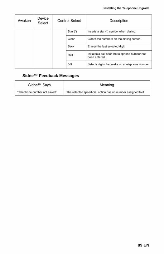
Installing the Telephone Upgrade
Sidne™ Feedback Messages
Star (*) Inserts a star (*) symbol when dialing.
Clear Clears the numbers on the dialing screen.
Back Erases the last selected digit.
Call Initiates a call after the telephone number has been entered.
0-9 Selects digits that make up a telephone number.
Sidne™ Says Meaning
“Telephone number not saved” The selected speed-dial option has no number assigned to it.
AwakenDevice Select
Control Select Description
89 EN
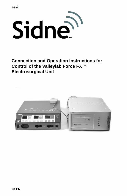
90 EN
Sidne™ Operating and Maintenance Manual AddendumConnection and Operation Instructions for Control of the Valleylab Force FX™ Electrosurgical Unit
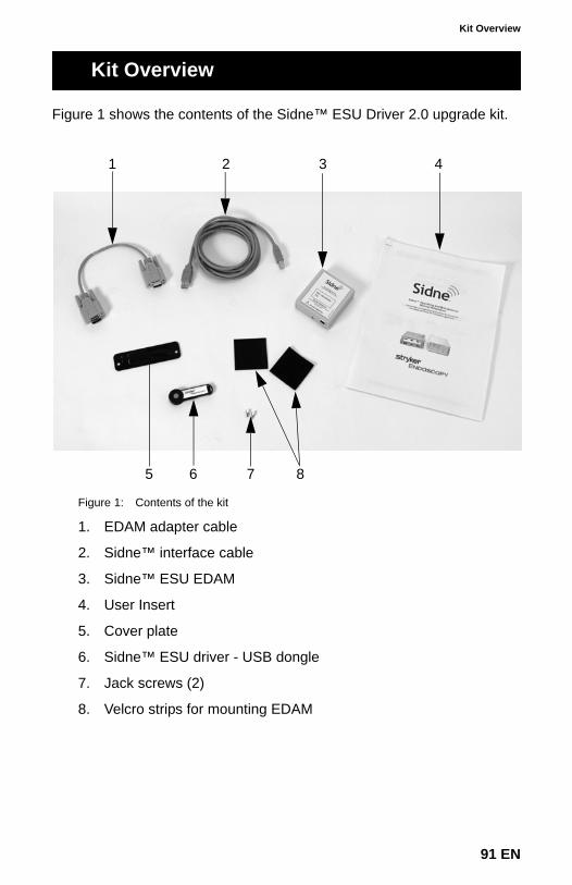
Kit Overview
Figure 1 shows the contents of the Sidne™ ESU Driver 2.0 upgrade kit.
Figure 1: Contents of the kit
1. EDAM adapter cable
2. Sidne™ interface cable
3. Sidne™ ESU EDAM
4. User Insert
5. Cover plate
6. Sidne™ ESU driver - USB dongle
7. Jack screws (2)
8. Velcro strips for mounting EDAM
Kit Overview
1 2 3 4
5 6 7 8
91 EN
This section is intended to give an outline of the start-up instructions for experienced users. Refer to the relevant section(s) of this addendum for further instructions.
1. Ensure that the ESU and Sidne™ are powered Off.
2. Install the cover plate (if necessary).
3. Connect the ESU to Sidne™.a. Connect the EDAM adapter cable to the ESU.b. Connect the EDAM adapter cable to the EDAM.c. Connect the Sidne™ interface cable to the EDAM.d. Connect the Sidne™ interface cable to Sidne™.e. Mount the EDAM.
4. Power On the Sidne™ console.
5. Install the ESU driver upgrade.
6. Sidne™ will restart. Wait for Sidne™ to say “Sidne™ ready” before powering On the ESU.
Caution Sidne™ should say “ESU Connected” and the EDAM LED should be flashing green within 20 seconds of powering On the ESU. A different LED output may indicate device problems. If the LED does not flash green after 20 seconds, refer to the “Troubleshooting Guide” of this addendum for instructions.
7. Power On the ESU.
This completes the installation procedure.
Quick Start-Up Guide
92 EN
Connecting the Electrosurgical Unit (ESU)
Warnings and CautionsPlease read this addendum and follow its instructions carefully. The words warning, caution, and note carry special meanings and should be carefully reviewed:
Warning The personal safety of the patient or physician may be involved. Disregarding this information could result in injury to the patient or physician.
Caution Special service procedures or precautions must be followed to avoid damaging the instrument.
Note Special information to make maintenance easier or important information more clear.
An exclamation mark within a triangle is intended to alert the user to the presence of important operating and maintenance instructions in the literature accompanying the product.
A lightning bolt within a triangle is intended to warn of the presence of hazardous voltage. Refer all service to authorized personnel.
Warning To avoid potential serious injury to the user and the patient and/or damage to this device, please note the following warnings:
1. To avoid potential serious injury to the user and patient and/or damage to this device, read the Valleylab Force FX™ Electrosurgical Unit (ESU) operating manual thoroughly and be familiar with its contents prior to using this equipment.
2. The ESU is designed to be used by a qualified physician familiar with its use. Misusing the ESU may cause injury to the patient and/or damage system components.
3. Carefully unpack the kit and check if any damage occurred during shipment. If damage is detected, DO NOT use the equipment.
Warning To avoid potential serious injury to the user and the patient and/or damage to this device, please note the following electrical warnings:
Connecting the Electrosurgical Unit (ESU)
93 EN
1. To prevent electrical shock to the patient and/or operating room personnel, do not immerse the ESU or allow fluid to enter the chassis or connector.
2. Before and after each use, inspect the cord insulation for cracks, nicks, cuts, dents, or depressions. Any irregularity will decrease the insulation effectiveness and may result in shocks to the patient and/or operating room personnel.
3. To prevent injury or electrical shock to the patient and/or operating room personnel, always power Off the ESU when connecting or disconnecting accessories.
Caution To avoid potential damage to this device, please note the following cautions:
1. Always power Off the ESU before connecting or disconnecting the Sidne™ interface kit.
2. Ensure that the Sidne™ ESU EDAM (hereafter referred to as “EDAM”) is securely mounted to the ESU or cart.
94 EN
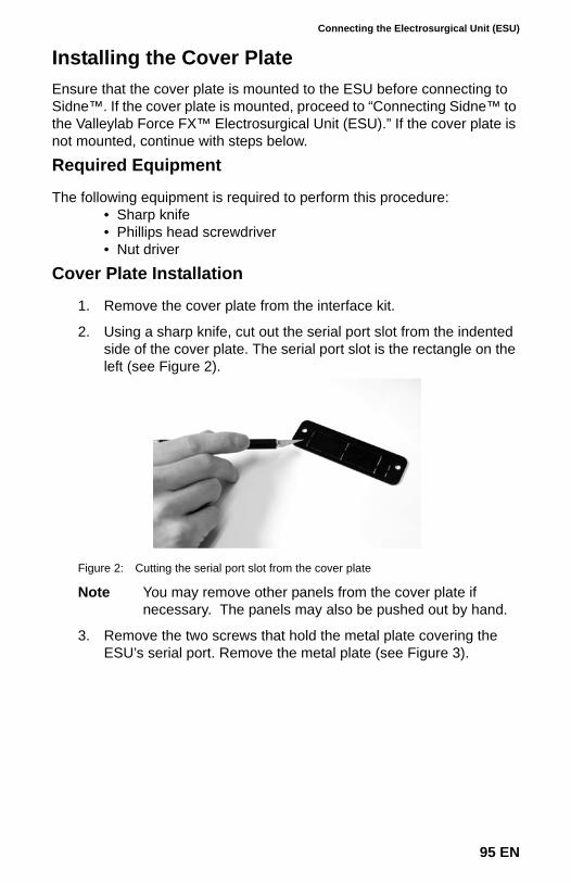
Connecting the Electrosurgical Unit (ESU)
Installing the Cover PlateEnsure that the cover plate is mounted to the ESU before connecting to Sidne™. If the cover plate is mounted, proceed to “Connecting Sidne™ to the Valleylab Force FX™ Electrosurgical Unit (ESU).” If the cover plate is not mounted, continue with steps below.
Required Equipment
The following equipment is required to perform this procedure:• Sharp knife• Phillips head screwdriver• Nut driver
Cover Plate Installation
1. Remove the cover plate from the interface kit.
2. Using a sharp knife, cut out the serial port slot from the indented side of the cover plate. The serial port slot is the rectangle on the left (see Figure 2).
Figure 2: Cutting the serial port slot from the cover plate
Note You may remove other panels from the cover plate if necessary. The panels may also be pushed out by hand.
3. Remove the two screws that hold the metal plate covering the ESU’s serial port. Remove the metal plate (see Figure 3).
95 EN
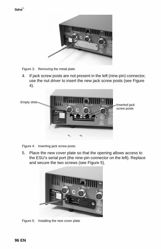
Figure 3: Removing the metal plate
4. If jack screw posts are not present in the left (nine-pin) connector, use the nut driver to insert the new jack screw posts (see Figure 4).
Figure 4: Inserting jack screw posts
5. Place the new cover plate so that the opening allows access to the ESU’s serial port (the nine-pin connector on the left). Replace and secure the two screws (see Figure 5).
Figure 5: Installing the new cover plate
Inserted jack screw posts
Empty slots
96 EN
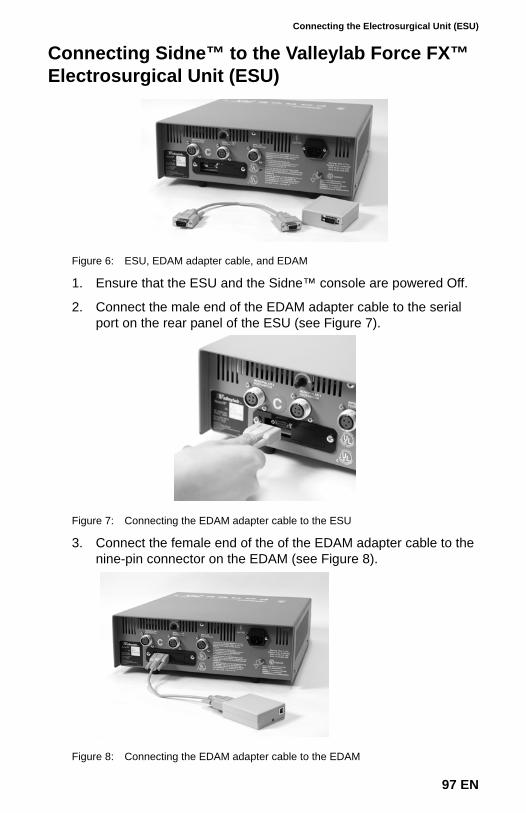
Connecting the Electrosurgical Unit (ESU)
Connecting Sidne™ to the Valleylab Force FX™ Electrosurgical Unit (ESU)
Figure 6: ESU, EDAM adapter cable, and EDAM
1. Ensure that the ESU and the Sidne™ console are powered Off.
2. Connect the male end of the EDAM adapter cable to the serial port on the rear panel of the ESU (see Figure 7).
Figure 7: Connecting the EDAM adapter cable to the ESU
3. Connect the female end of the of the EDAM adapter cable to the nine-pin connector on the EDAM (see Figure 8).
Figure 8: Connecting the EDAM adapter cable to the EDAM
97 EN
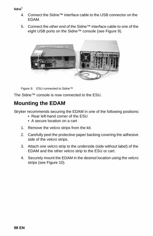
4. Connect the Sidne™ interface cable to the USB connector on the EDAM.
5. Connect the other end of the Sidne™ interface cable to one of the eight USB ports on the Sidne™ console (see Figure 9).
Figure 9: ESU connected to Sidne™
The Sidne™ console is now connected to the ESU.
Mounting the EDAMStryker recommends securing the EDAM in one of the following positions:
• Rear left-hand corner of the ESU• A secure location on a cart
1. Remove the velcro strips from the kit.
2. Carefully peel the protective paper backing covering the adhesive side of the velcro strips.
3. Attach one velcro strip to the underside (side without label) of the EDAM and the other velcro strip to the ESU or cart.
4. Securely mount the EDAM in the desired location using the velcro strips (see Figure 10).
98 EN
Connecting the Electrosurgical Unit (ESU)
Figure 10: Mounting the EDAM to the ESU
99 EN
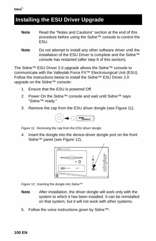
Note Read the “Notes and Cautions” section at the end of this procedure before using the Sidne™ console to control the ESU.
Note Do not attempt to install any other software driver until the installation of the ESU Driver is complete and the Sidne™ console has restarted (after step 6 of this section).
The Sidne™ ESU Driver 2.0 upgrade allows the Sidne™ console to communicate with the Valleylab Force FX™ Electrosurgical Unit (ESU). Follow the instructions below to install the Sidne™ ESU Driver 2.0 upgrade on the Sidne™ console:
1. Ensure that the ESU is powered Off.
2. Power On the Sidne™ console and wait until Sidne™ says “Sidne™ ready.”
3. Remove the cap from the ESU driver dongle (see Figure 11).
Figure 11: Removing the cap from the ESU driver dongle
4. Insert the dongle into the device-driver dongle port on the front Sidne™ panel (see Figure 12).
Figure 12: Inserting the dongle into Sidne™
Note After installation, the driver dongle will work only with the system to which it has been installed. It can be reinstalled on that system, but it will not work with other systems.
5. Follow the voice instructions given by Sidne™:
Installing the ESU Driver Upgrade
100 EN
Installing the ESU Driver Upgrade
Caution Programming the digital board may take several minutes. To avoid equipment damage, please do not remove the dongle card before Sidne™ says, “Please remove card.”
6. Wait as Sidne™ restarts. When the console says, “Sidne™ ready,” the driver is installed and ready for use.
Caution Sidne™ should say “ESU Connected” and the EDAM LED should be flashing green within 20 seconds of powering On the ESU. A different LED output may indicate device problems. If the LED does not flash green after 20 seconds, refer to the “Troubleshooting Guide” of this addendum for instructions.
7. Power On the ESU.
Please retain this addendum for future reference.
When Sidne™ says this... do this...
“Software card detected. Please stand by.”
Wait for the next instruction.
“Programming 10% complete.”*
* Sidne™ will announce the completion percentage throughout the installation process. Do not remove the dongle until Sidne says, “please remove card.”
Wait for the next instruction.
“Programming failed.”**
** Sidne™ will announce this message only if the programming has failed.
Remove and reinsert the dongle.
“Programming complete.” Wait for the next instruction.
“Please remove card.” Remove the driver dongle from the Sidne™ console.
101 EN
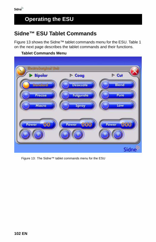
Sidne™ ESU Tablet CommandsFigure 13 shows the Sidne™ tablet commands menu for the ESU. Table 1 on the next page describes the tablet commands and their functions.
Tablet Commands Menu
Figure 13: The Sidne™ tablet commands menu for the ESU
Operating the ESU
102 EN
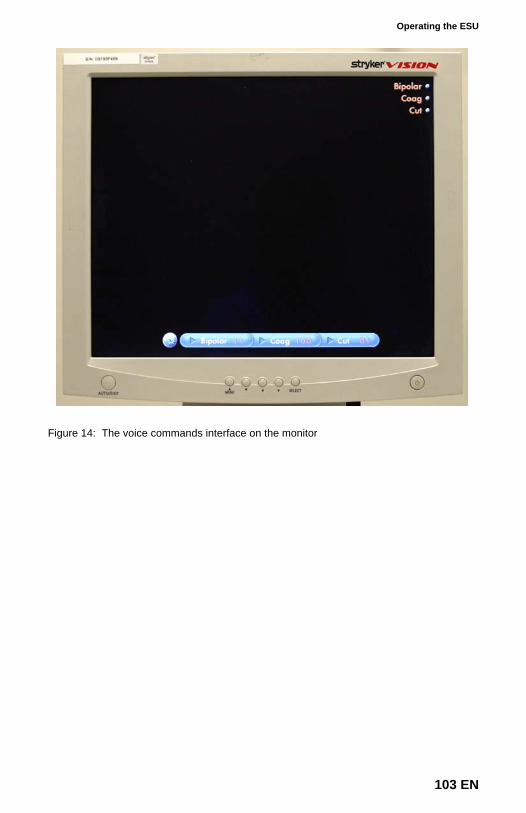
Operating the ESU
Figure 14: The voice commands interface on the monitor
103 EN
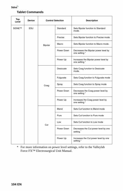
Tablet Commands
Top Level Device Control Selection Description
SIDNE™ ESU
Bipolar
Standard Sets Bipolar function to Standard mode.
Precise Sets Bipolar function to Precise mode.
Macro Sets Bipolar function to Macro mode.
Power Down Decreases the Bipolar power level by one setting.*
Power Up Increases the Bipolar power level by one setting.*
Coag
Desiccate Sets Coag function to Desiccate mode.
Fulgurate Sets Coag function to Fulgurate mode
Spray Sets Coag function to Spray mode
Power Down Decreases the Coag power level by one setting.*
Power Up Increases the Coag power level by one setting.*
Cut
Blend Sets Cut function to Blend mode
Pure Sets Cut function to Pure mode
Low Sets Cut function to Low mode
Power Down Decreases the Cut power level by one setting.*
* For more information on power level settings, refer to the Valleylab Force FX™ Electrosurgical Unit Manual.
Power Up Increases the Cut power level by one setting.*
104 EN
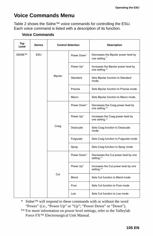
Operating the ESU
Voice Commands Menu Table 2 shows the Sidne™ voice commands for controlling the ESU. Each voice command is listed with a description of its function.
Voice Commands
Top Level Device Control Selection Description
SIDNE™ ESU
Bipolar
Power Down*
* Sidne™ will respond to these commands with or without the word “Power” (i.e., “Power Up” or “Up”; “Power Down” or “Down”).
Decreases the Bipolar power level by one setting.**
** For more information on power level settings, refer to the Valleylab Force FX™ Electrosurgical Unit Manual.
Power Up* Increases the Bipolar power level by one setting.**
Standard Sets Bipolar function to Standard mode.
Precise Sets Bipolar function to Precise mode.
Macro Sets Bipolar function to Macro mode.
Coag
Power Down* Decreases the Coag power level by one setting.**
Power Up* Increases the Coag power level by one setting.**
Desiccate Sets Coag function to Desiccate mode.
Fulgurate Sets Coag function to Fulgurate mode
Spray Sets Coag function to Spray mode
Cut
Power Down* Decreases the Cut power level by one setting.**
Power Up* Increases the Cut power level by one setting.**
Blend Sets Cut function to Blend mode
Pure Sets Cut function to Pure mode
Low Sets Cut function to Low mode
105 EN
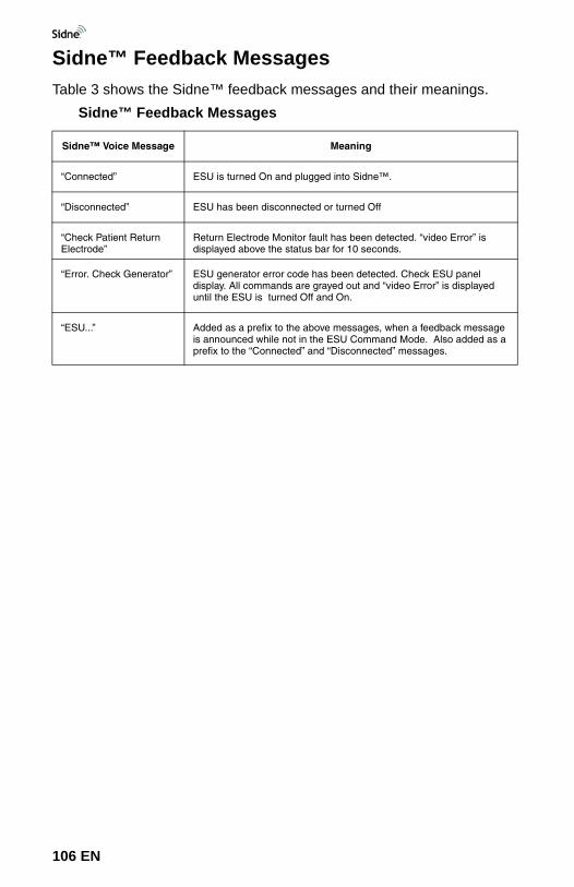
Sidne™ Feedback MessagesTable 3 shows the Sidne™ feedback messages and their meanings.
Sidne™ Feedback Messages
Sidne™ Voice Message Meaning
“Connected” ESU is turned On and plugged into Sidne™.
“Disconnected” ESU has been disconnected or turned Off
“Check Patient Return Electrode”
Return Electrode Monitor fault has been detected. “video Error” is displayed above the status bar for 10 seconds.
“Error. Check Generator” ESU generator error code has been detected. Check ESU panel display. All commands are grayed out and “video Error” is displayed until the ESU is turned Off and On.
“ESU...” Added as a prefix to the above messages, when a feedback message is announced while not in the ESU Command Mode. Also added as a prefix to the “Connected” and “Disconnected” messages.
106 EN
Troubleshooting Guide
Table 4 shows the most common errors and possible solutions to each.Troubleshooting Guide
Problem Possible Solution
1. No access to ESU through Sidne™
• This problem has several possible causes. Please see solutions for each problem:
a. EDAM LED stays flashing red*
• Contact Stryker Endoscopy or your local Stryker sales representative for firmware upgrade.
b. EDAM LED stays solid red*
• The ESU is not communicating properly with the Sidne™ ESU EDAM. Ensure that the ESU is properly connected to Sidne™. See the “Connecting Sidne™ to the Valleylab Force FX™ Electrosurgical Unit” section of this addendum for more details. Attempt the following solutions in order:
1. Power Off ESU.
2. Ensure that the ESU EDAM adapter cable is plugged into the EDAM.
3. Ensure that the ESU EDAM adapter cable is plugged into the ESU.
4. Power On ESU.
Troubleshooting Guide
107 EN
c. EDAM LED stays solid yellow*
• Sidne™ is not communicating properly with the Sidne™ ESU EDAM. See the “Connecting Sidne™ to the Valleylab Force FX™ Electrosurgical Unit” section of this addendum for more details. Attempt the following fixes in order:
1. Power Off ESU.
2. Ensure Sidne™ is powered On.
3. Ensure that the Sidne™ interface cable is plugged into the EDAM.
4. Ensure that the Sidne™ interface cable is plugged into Sidne™.
5. Power On ESU.
2. Sidne™ says “ESU Disconnected”
• Power Off ESU.• Ensure that the ESU is properly connected to
Sidne™. See the “Connecting Sidne™ to the Valleylab Force FX™ Electrosurgical Unit” section of this addendum for further instructions.
• Power On ESU.
3. Sidne™ says “Check patient return electrode”
• Refer to the Valleylab Force FX™ Electrosurgical Unit Manual for further details.
4. Sidne™ says “Error. Check generator”
• Refer to the Valleylab Force FX™ Electrosurgical Unit Manual for further details.
* The EDAM LED should flash green when the system is functioning normally.
Problem Possible Solution
108 EN
Electromagnetic Compatibility Tables
Like other electrical medical accesories, the Sidne ESU EDAM requires special precautions to ensure electromagnetic compatibility with other electrical medical devices. To ensure electromagnetic compatibility (EMC), the Sidne ESU EDAM must be installed and operated according to the EMC information provided in this manual.
Warning Do not use cables or accessories other than those provided with the Sidne ESU EDAM, as this may result in increased electromagnetic emissions or decreased immunity to such emissions.
Warning If the Sidne ESU EDAM is used adjacent to or stacked with other equipment, observe and verify normal operation of the Sidne ESU EDAM in the configuration it will be used in prior to using it in a surgical procedure. Consult the tables below for guidance in positioning the Sidne ESU EDAM.
Caution Portable and mobile RF communications equipment may affect the normal function of the Sidne ESU EDAM.
The Sidne ESU EDAM has been designed and tested to comply with IEC 60601-1-2:2001 requirements for EMC with other devices.
Electromagnetic Compatibility Tables
109 EN
Guidance and Manufacturer's Declaration: Electromagnetic Immunity
Sidne ESU EDAM is intended for use in the electromagnetic environment specified below. The customer or the user of Sidne ESU EDAM should ensure that it is used in such an environment.
Immunity Test IEC 60601 Test Level
Compliance Level
Electromagnetic Environment: Guidance
Electrostatic Discharge (ESD)IEC61000-4-2
±6kV contact±8kV air
±2,4,6kV contact±2,4,8kV air
Floors should be wood, concrete, or ceramic tile. If floors are covered with synthetic material, the relative humidity should be at least 30%.
Electrical fast transient/burst IEC61000-4-4
±2kV for power supply lines ±1kV for input/output lines
±2kV for power supply lines (Sidne)±1kV for input/output lines
Mains power quality should be that of a typical commercial or hospital environment.
Power frequency (50/60Hz) magnetic fieldIEC 61000-4-8
3 A/m3 A/m
Power-frequency magnetic fields should be at levels characteristic of a typical location in a typical commercial or hospital environment.
NOTE: Ut is the a.c. mains voltage prior to application of the test level.
Portable and mobile RF communications equipment should be used no closer to any part of the Sidne ESU EDAM system, including its cables, than the recommended separation distance calculated from the equation applicable to the frequency of the transmitter.
Conducted RFIEC 61000-4-6
3 Vrms150 kHz to 80 MHz
3 VRecommended Separation Distance
d 1.17 P=
110 EN
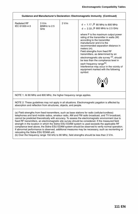
Electromagnetic Compatibility Tables
Radiated RFIEC 61000-4-3
3 V/m80MHz to 2.5 GHz
3 V/m 80 MHz to 800 MHz
800 MHz to 2.5 GHz
where P is the maximum output power rating of the transmitter in watts (W) according to the transmitter manufacturer and d is the recommended separation distance in meters (m).Field strengths from fixed RF transmitters, as determined by an electromagnetic site survey (a), should be less than the compliance level in each frequency range(b).Interference may occur in the vicinity of equipment marked with the following symbol:
NOTE 1: At 80 MHz and 800 MHz, the higher frequency range applies.
NOTE 2: These guidelines may not apply in all situations. Electromagnetic pagation is affected by absorption and reflection from structures, objects, and people.
(a) Field strengths from fixed transmitters, such as base stations for radio (cellular/cordless) telephones and land mobile radios, amateur radio, AM and FM radio broadcast, and TV broadcast, cannot be predicted theoretically with accuracy. To assess the electromagnetic environment due to fixed RF transmitters, an electromagnetic site survey should be considered. If the measured field strength in the location in which the Sidne ESU EDAM system is used exceeds the applicable RF compliance level above, the Sidne ESU EDAM system should be observed to verify normal operation. If abnormal performance is observed, additional measures may be necessary, such as reorienting or relocating the Sidne ESU EDAM unit.(b) Over the frequency range 150 kHz to 80 MHz, field strengths should be less than 3 V/m.
Guidance and Manufacturer's Declaration: Electromagnetic Immunity (Continued)
d 1.17 P=
d 2.33 P=
111 EN
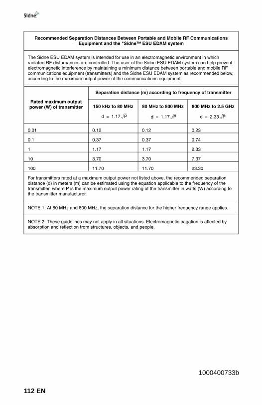
Recommended Separation Distances Between Portable and Mobile RF Communications Equipment and the "Sidne™ ESU EDAM system
The Sidne ESU EDAM system is intended for use in an electromagnetic environment in which radiated RF disturbances are controlled. The user of the Sidne ESU EDAM system can help prevent electromagnetic interference by maintaining a minimum distance between portable and mobile RF communications equipment (transmitters) and the Sidne ESU EDAM system as recommended below, according to the maximum output power of the communications equipment.
Rated maximum output power (W) of transmitter
Separation distance (m) according to frequency of transmitter
150 kHz to 80 MHz 80 MHz to 800 MHz 800 MHz to 2.5 GHz
0.01 0.12 0.12 0.23
0.1 0.37 0.37 0.74
1 1.17 1.17 2.33
10 3.70 3.70 7.37
100 11.70 11.70 23.30
For transmitters rated at a maximum output power not listed above, the recommended separation distance (d) in meters (m) can be estimated using the equation applicable to the frequency of the transmitter, where P is the maximum output power rating of the transmitter in watts (W) according to the transmitter manufacturer.
NOTE 1: At 80 MHz and 800 MHz, the separation distance for the higher frequency range applies.
NOTE 2: These guidelines may not apply in all situations. Electromagnetic pagation is affected by absorption and reflection from structures, objects, and people.
d 1.17 P= d 1.17 P= d 2.33 P=
1000400733b
112 EN
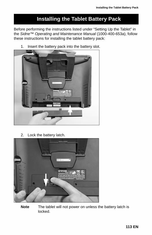
Installing the Tablet Battery Pack
113 EN
Before performing the instructions listed under “Setting Up the Tablet” in the Sidne™ Operating and Maintenance Manual (1000-400-653a), follow these instructions for installing the tablet battery pack:
1. Insert the battery pack into the battery slot.
2. Lock the battery latch.
Note The tablet will not power on unless the battery latch is locked.
Installing the Tablet Battery Pack
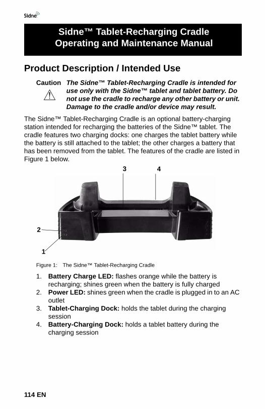
Product Description / Intended UseCaution The Sidne™ Tablet-Recharging Cradle is intended for
use only with the Sidne™ tablet and tablet battery. Do not use the cradle to recharge any other battery or unit. Damage to the cradle and/or device may result.
The Sidne™ Tablet-Recharging Cradle is an optional battery-charging station intended for recharging the batteries of the Sidne™ tablet. The cradle features two charging docks: one charges the tablet battery while the battery is still attached to the tablet; the other charges a battery that has been removed from the tablet. The features of the cradle are listed in Figure 1 below.
Figure 1: The Sidne™ Tablet-Recharging Cradle
1. Battery Charge LED: flashes orange while the battery is recharging; shines green when the battery is fully charged
2. Power LED: shines green when the cradle is plugged in to an AC outlet
3. Tablet-Charging Dock: holds the tablet during the charging session
4. Battery-Charging Dock: holds a tablet battery during the charging session
Sidne™ Tablet-Recharging CradleOperating and Maintenance Manual
1
2
3 4
114 EN
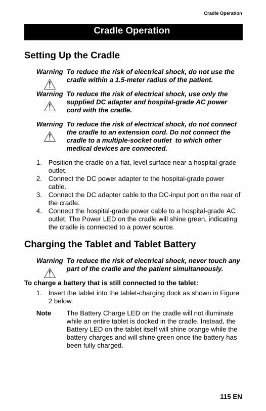
Cradle Operation
Setting Up the CradleWarning To reduce the risk of electrical shock, do not use the
cradle within a 1.5-meter radius of the patient.
Warning To reduce the risk of electrical shock, use only the supplied DC adapter and hospital-grade AC power cord with the cradle.
Warning To reduce the risk of electrical shock, do not connect the cradle to an extension cord. Do not connect the cradle to a multiple-socket outlet to which other medical devices are connected.
1. Position the cradle on a flat, level surface near a hospital-grade outlet.
2. Connect the DC power adapter to the hospital-grade power cable.
3. Connect the DC adapter cable to the DC-input port on the rear of the cradle.
4. Connect the hospital-grade power cable to a hospital-grade AC outlet. The Power LED on the cradle will shine green, indicating the cradle is connected to a power source.
Charging the Tablet and Tablet BatteryWarning To reduce the risk of electrical shock, never touch any
part of the cradle and the patient simultaneously.
To charge a battery that is still connected to the tablet:1. Insert the tablet into the tablet-charging dock as shown in Figure
2 below.
Note The Battery Charge LED on the cradle will not illuminate while an entire tablet is docked in the cradle. Instead, the Battery LED on the tablet itself will shine orange while the battery charges and will shine green once the battery has been fully charged.
Cradle Operation
115 EN
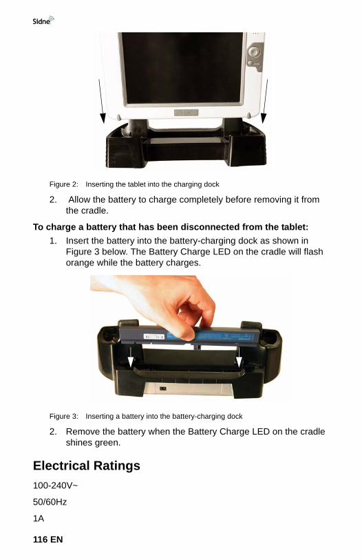
Figure 2: Inserting the tablet into the charging dock
2. Allow the battery to charge completely before removing it from the cradle.
To charge a battery that has been disconnected from the tablet:1. Insert the battery into the battery-charging dock as shown in
Figure 3 below. The Battery Charge LED on the cradle will flash orange while the battery charges.
Figure 3: Inserting a battery into the battery-charging dock
2. Remove the battery when the Battery Charge LED on the cradle shines green.
Electrical Ratings100-240V~
50/60Hz
1A
116 EN

Cradle Cleaning and Maintenance
CleaningWarning To reduce the risk of electrical shock, unplug the
cradle from the electrical outlet before cleaning the unit.
Caution Do not immerse the cradle in any liquid, as product damage will result.
Caution Do not use solvents, such as alcohol, or cleaning solutions that contain ammonia to clean the cradle, as product damage may result.
Caution Do not sterilize the cradle, as product damage may result.
1. Wipe the cradle with a soft, dry cloth.
MaintenanceThe cradle requires no preventative or periodic maintenance.
Refer to the Sidne™ Operation and Maintenance Manual for warranty and repair information.
Cradle Cleaning and Maintenance
Warranty and Repairs
1000400716a
117 EN

1000-400-653 Rev. D
5900 Optical CourtSan Jose, CA 95138USA 1-408-754-20001-800-624-4422
Stryker European RepresentativeRegulatory Manager
ZAC Satolas Green PusignanAv. de Satolas Green69881 MEYZIEU Cedex, France