sts-96 - johnson space center · pdf filevisitors to a new star in orbit on mission sts-96,...
TRANSCRIPT

First VisitFirst Visit to an to an
Outpost in OrbitOutpost in Orbit
WWW.SHUTTLEPRESSKIT.COM
Updated May 20, 1999
STS-96STS-96

STS-96 Table of Contents*Grayed text - not published
Mission Overview .............................................................................................. 1
Mission Profile ................................................................................................... 6
Shuttle Reference
Shuttle Abort History ............................................................................................ 9
Shuttle Abort Modes........................................................................................... 11
Crew................................................................................................................... 18
Flight Day Summary.......................................................................................... 23
Rendezvous
Docking Mechanisms......................................................................................... 27
Rendezvous and Docking................................................................................... 29
Undocking, Separation and Fly-Around ............................................................. 33
EVA
Space Walk to Install U.S., Russian Crane Systems ........................................ 34
Payloads
Cargo Transfer.................................................................................................... 38
Integrated Cargo Carrier..................................................................................... 42
Integrated Vehicle Health Monitoring HEDS Technology Demonstration 2............................................................................................ 44
MIRTs Changeout............................................................................................... 47
Shuttle Vibration Forces Experiment.................................................................. 49
SPACEHAB........................................................................................................ 51
Student-Tracked Atmospheric Research Satellite for Heuristic International Networking Equipment (STARSHINE) ...................... 55
*EXPERIMENTS

DTO/DSO/RME
DTO 686 Heat Exchange Unit Evaluation........................................................... 58
DTO 1214 Resource Transfer Line Capability Evaluation .................................. 59
DTO 700-14 Single-String Global Positioning System....................................... 60
DTO 847 Solid-State Star Tracker Size Limitations ........................................... 61
DTO 700-15 Space Integrated Global Positioning System/Inertial Navigation System................................................................ 62
DTO 690 Urine Collection Device....................................................................... 63
ISS Overview .................................................................................................... 64
Unity................................................................................................................... 71
Zarya .................................................................................................................. 73
Media Assistance.............................................................................................. 75
Contacts ............................................................................................................ 77

STS-96
Mission Overview
DISCOVERY'S CREW TO MAKE FIRST STATION VISIT
The Shuttle Discovery's international crew of seven will become the firstvisitors to a new star in orbit on mission STS-96, preparing the InternationalSpace Station for the arrival of its early living quarters and laying out awelcome mat for the first station crew.
Discovery will spend six days linked to the new outpost as the crew transfersand installs gear that could not be launched aboard the Zarya and Unitymodules due to weight limitations. The Shuttle will carry more than 3,600pounds of supplies to be stored aboard the station, ranging from food andclothes for the first crew to laptop computers, a printer and cameras.
1

Discovery's crew, led by U.S. Navy Commander Kent Rominger, 42, reflectsthe global nature of the station with three of five international partnersrepresented. Included are cosmonaut Valery Tokarev, 46, a colonel in theRussian Air Force, and Canadian Space Agency astronaut Julie Payette, 35,who will become the first Canadian to board the station. U.S. Air Force Lt.Col. Rick Husband, 41, will serve as pilot, and a spacewalk will be performedby astronauts Tammy Jernigan,40, and Dr. Daniel Barry, 42. Jernigan andBarry will attach a United States-built spacewalkers' "crane" and parts of aRussian-built crane to the exterior for use on future missions. Astronaut EllenOchoa rounds out the crew as flight engineer and operator of the Shuttle'smechanical arm.
Discovery's mission will set the stage for the launch this fall of theRussian-provided Service Module, the first station living quarters, and thearrival in early 2000 of the first three-person station crew. STS-96 is the firstof two Shuttle missions scheduled to visit the International Space Station thisyear to continue its assembly, an unprecedented task that turns Earth orbitinto an ever-changing construction site, joining more than 100 elements on45 assembly flights.
2

The International Space Station will allow humankind to harness as neverbefore one of the fundamental forces of nature – gravity – to performresearch that may result in new medicines, materials and industries onEarth. The station's scientific studies, performed in six state-of-the-artlaboratories, may even lead to a new understanding of the fundamental lawsof nature while they pave the way for the future human exploration of space.Partners in the United States-led station include Canada, 11 member nationsof the European Space Agency, Japan and Russia. Italy and Brazil also arecontributing.
3

Much of the gear destined for the station will be housed inside a doubleSpacehab module in Discovery's payload bay. The spacewalking gear andcranes will be stored outside in the Shuttle bay on a new piece of equipmentcalled the Integrated Cargo Carrier, a removable platform that will be used onmany future station assembly flights. The carrier, which will remain in theShuttle bay throughout STS-96, also includes a large, new spacewalkingequipment storage box developed by Spacehab.
In addition to its primary cargo of station supplies, Discovery will carry aloft asmall satellite called Starshine that will provide educational observations forstudents around the world. More than 1,000 schools across America and theworld have helped construct the satellite and will participate in the project,calculating its orbit as they learn about math and physics. Although onlyslightly larger than a basketball, Starshine is covered by almost 900 highlypolished mirrors that will make it visible from the ground. It will be releasedfrom Discovery after the Shuttle has left the station.
Discovery also will conduct several evaluations of equipment for future useon the station and the Shuttle. Two new Shuttle sensor systems will betested. One system, called the Shuttle Vibration Forces experiment, willrecord vibrations between the Shuttle and its cargo to assist in planning
4

future flights. Another test, called the Integrated Vehicle Health MonitoringSystem, will send information on several of Discovery's systems to theKennedy Space Center, FL, during flight and may shorten the time needed toprepare Shuttles for launch. Another evaluation will check equipment thatmay be used on future flights to transfer water and fluids from the Shuttle tothe station. Another study, called the Volatile Removal Assembly, will test theoperation of equipment that will be used to help recycle station wastewater.
Already easily visible from Earth, the International Space Station will growbrighter as Discovery docks and continue to increase in magnitude as itsassembly in orbit progresses during the next five years. Components built atfactories around the world are now being readied for upcoming launches atthe Kennedy Space Center and at the Russian launch site, the BaikonurCosmodrome in Kazakstan.
Updated: 05/14/1999
5

STS-96
Discovery OV103Launch: Thursday, May 27, 1999 6:48 AM (eastern time)
Mission ObjectivesThe major objective of the first shuttle mission of the year is the transfer ofalmost two tons of logistical supplies from the shuttle Discovery to theInternational Space Station.
These supplies will be used to not only continue the outfitting of the Unityand Zarya modules already joined together in orbit, but will be used by afuture Shuttle assembly crew later this year to set up the Russian ServiceModule for occupancy by a three-man crew early next year.
In addition to the supply delivery, the astronauts will deploy a small satellitecalled STARSHINE which will be observed by international students onEarth as they calculate its precise orbit and the rate of its orbital decay overa period of time.
The seven crew members will also collect data from an experimentdesigned to test the amount of vibration imparted on shuttle-based payloadsand will begin to demonstrate the effect of technological upgrades to theshuttle through the use of orbiter health monitoring devices designed toimprove the quality of life aboard future shuttles while making their usemore efficient over time.
6

Crew Commander: Kent V. Rominger
Pilot: Rick D. Husband
Mission Specialist 1: Tamara E. Jernigan
Mission Specialist 2: Ellen Ochoa
Mission Specialist 3: Daniel T. Barry
Mission Specialist 4: Julie Payette
Mission Specialist 5: Valery Tokarev
Launch Orbiter: Discovery OV103
Launch Site: Pad 39-B Kennedy Space Center
Launch Window: 10 minutes
Altitude: 173nm (205 nm for rendezvous)
Inclination: 51.6
Duration: 9 Days 19 Hrs. 55 Min.
Vehicle Data Shuttle Liftoff Weight: 4,514,454 lbs.
Orbiter/Payload Liftoff Weight: 262,035 lbs.
Orbiter/Payload LandingWeight:
220,980 lbs.
Payload Weights
IVHM-2 254 lbs.
STARSHINE 353 lbs.
ICC 3050 lbs.
SVFE 327 lbs.
SPACEHAB 16072 lbs.
Software Version: OI-27
Space Shuttle Main Engines
SSME 1: SN-2047 (2nd flt.) SSME 2: SN-2051 (1st flt.) SSME 3: SN-2049 (1st flt.)
External Tank: ET-100 (4th Super Light Weight Tank)
7

SRB Set: BI098
Auxiliary Power Units:
APU-1: SN-310 APU-2: SN-204 APU-3: SN-404
Fuel Cells:
FC-1: SN-117 FC-2: SN-111 FC-3: SN-103
Shuttle Aborts
Abort Landing Sites
RTLS: Shuttle Landing Facility, KSC
TAL: Zaragoza, Spain; Alternates: Ben Guerrir, Moron
AOA: Shuttle Landing Facility, KSC; Alternates: White Sands Space Harbor
Landing Landing Date: 06/06/99
Landing Time: 2:43 AM (eastern time)
Primary Landing Site: Shuttle Landing Facility, KSC
First alternate, Edwards Air Force BaseSecond alternate, White Sands Space Harbor
PayloadsCargo Bay
Integrated Vehicle Health Monitoring HEDS Technology Demonstration 2
Student-Tracked Atmospheric Research Satellite for Heuristic International NetworkingEquipment (STARSHINE)
Integrated Cargo Carrier
Shuttle Vibration Forces Experiment
SPACEHAB
Spacehab
MIRTs Changeout
Cargo Transfer
8

STS-96
Shuttle Reference and Data
Shuttle Abort History
RSLS Abort History:
(STS-41 D) June 26, 1984The countdown for the second launch attempt for Discovery’s maiden flightended at T-4 seconds when the orbiter’s computers detected a sluggishvalve in main engine #3. The main engine was replaced and Discovery wasfinally launched on August 30, 1984.
(STS-51 F) July 12, 1985The countdown for Challenger’s launch was halted at T-3 seconds whenon-board computers detected a problem with a coolant valve on mainengine #2. The valve was replaced and Challenger was launched on July29, 1985.
(STS-55) March 22, 1993The countdown for Columbia’s launch was halted by on-board computersat T-3 seconds following a problem with purge pressure readings in theoxidizer preburner on main engine #2 Columbia’s three main engines werereplaced on the launch pad, and the flight was rescheduled behindDiscovery’s launch on STS-56. Columbia finally launched on April 26,1993.
(STS-51) August 12, 1993The countdown for Discovery’s third launch attempt ended at the T-3second mark when on-board computers detected the failure of one of foursensors in main engine #2 which monitor the flow of hydrogen fuel to theengine. All of Discovery’s main engines were ordered replaced on thelaunch pad, delaying the Shuttle’s fourth launch attempt until September12, 1993.
(STS-68) August 18, 1994The countdown for Endeavour’s first launch attempt ended 1.9 secondsbefore liftoff when on-board computers detected higher than acceptablereadings in one channel of a sensor monitoring the discharge temperatureof the high pressure oxidizer turbopump in main engine #3. A test firing ofthe engine at the Stennis Space Center in Mississippi on September 2ndconfirmed that a slight drift in a fuel flow meter in the engine caused aslight increase in the turbopump’s temperature. The test firing alsoconfirmed a slightly slower start for main engine #3 during the pad abort,which could have contributed to the higher temperatures. After Endeavourwas brought back to the Vehicle Assembly Building to be outfitted withthree replacement engines, NASA managers set October 2nd as the datefor Endeavour’s second launch attempt.
9

Abort to Orbit History:
(STS-51 F) July 29, 1985After an RSLS abort on July 12, 1985, Challenger was launched on July29, 1985. Five minutes and 45 seconds after launch, a sensor problemresulted in the shutdown of center engine #1, resulting in a safe "abort toorbit" and successful completion of the mission.
Updated: 05/11/1999
10

STS-96
Shuttle Reference and Data
Shuttle Abort Modes
RSLS ABORTS
These occur when the onboard Shuttle computers detect a problem andcommand a halt in the launch sequence after taking over from the GroundLaunch Sequencer and before Solid Rocket Booster ignition.
ASCENT ABORTS
Selection of an ascent abort mode may become necessary if there is afailure that affects vehicle performance, such as the failure of a spaceshuttle main engine or an orbital maneuvering system. Other failuresrequiring early termination of a flight, such as a cabin leak, might alsorequire the selection of an abort mode.
There are two basic types of ascent abort modes for space shuttle missions:intact aborts and contingency aborts. Intact aborts are designed to providea safe return of the orbiter to a planned landing site. Contingency aborts aredesigned to permit flight crew survival following more severe failures whenan intact abort is not possible. A contingency abort would generally result ina ditch operation.
INTACT ABORTS
There are four types of intact aborts: abort to orbit (ATO), abort once around(AOA), transoceanic abort landing (TAL) and return to launch site (RTLS).
Return to Launch Site
The RTLS abort mode is designed to allow the return of the orbiter, crew,and payload to the launch site, Kennedy Space Center, approximately 25minutes after lift-off.
The RTLS profile is designed to accommodate the loss of thrust from onespace shuttle main engine between lift-off and approximately four minutes20 seconds, at which time not enough main propulsion system propellantremains to return to the launch site.
11

An RTLS can be considered to consist of three stages-a powered stage,during which the space shuttle main engines are still thrusting; an ETseparation phase; and the glide phase, during which the orbiter glides to alanding at the Kennedy Space Center. The powered RTLS phase beginswith the crew selection of the RTLS abort, which is done after solid rocketbooster separation. The crew selects the abort mode by positioning the abortrotary switch to RTLS and depressing the abort push button. The time atwhich the RTLS is selected depends on the reason for the abort. Forexample, a three-engine RTLS is selected at the last moment, approximatelythree minutes 34 seconds into the mission; whereas an RTLS chosen due toan engine out at lift-off is selected at the earliest time, approximately twominutes 20 seconds into the mission (after solid rocket booster separation).
After RTLS is selected, the vehicle continues downrange to dissipate excessmain propulsion system propellant. The goal is to leave only enough mainpropulsion system propellant to be able to turn the vehicle around, fly backtowards the Kennedy Space Center and achieve the proper main enginecutoff conditions so the vehicle can glide to the Kennedy Space Center afterexternal tank separation. During the downrange phase, a pitch-aroundmaneuver is initiated (the time depends in part on the time of a space shuttlemain engine failure) to orient the orbiter/external tank configuration to aheads up attitude, pointing toward the launch site. At this time, the vehicle isstill moving away from the launch site, but the space shuttle main enginesare now thrusting to null the downrange velocity. In addition, excess orbitalmaneuvering system and reaction control system propellants are dumped bycontinuous orbital maneuvering system and reaction control system enginethrustings to improve the orbiter weight and center of gravity for the glidephase and landing.
12

The vehicle will reach the desired main engine cutoff point with less than 2percent excess propellant remaining in the external tank. At main enginecutoff minus 20 seconds, a pitch-down maneuver (called poweredpitch-down) takes the mated vehicle to the required external tank separationattitude and pitch rate. After main engine cutoff has been commanded, theexternal tank separation sequence begins, including a reaction controlsystem translation that ensures that the orbiter does not recontact theexternal tank and that the orbiter has achieved the necessary pitch attitude tobegin the glide phase of the RTLS.
After the reaction control system translation maneuver has been completed,the glide phase of the RTLS begins. From then on, the RTLS is handledsimilarly to a normal entry.
Transoceanic Abort Landing
The TAL abort mode was developed to improve the options available when aspace shuttle main engine fails after the last RTLS opportunity but before thefirst time that an AOA can be accomplished with only two space shuttlemain engines or when a major orbiter system failure, for example, a largecabin pressure leak or cooling system failure, occurs after the last RTLSopportunity, making it imperative to land as quickly as possible.
In a TAL abort, the vehicle continues on a ballistic trajectory across theAtlantic Ocean to land at a predetermined runway. Landing occursapproximately 45 minutes after launch. The landing site is selected near thenominal ascent ground track of the orbiter in order to make the most efficientuse of space shuttle main engine propellant. The landing site also must havethe necessary runway length, weather conditions and U.S. State Departmentapproval. Currently, the three landing sites that have been identified for a dueeast launch are Moron,, Spain; Dakar, Senegal; and Ben Guerur, Morocco(on the west coast of Africa).
13

To select the TAL abort mode, the crew must place the abort rotary switch inthe TAL/AOA position and depress the abort push button before main enginecutoff. (Depressing it after main engine cutoff selects the AOA abort mode.)The TAL abort mode begins sending commands to steer the vehicle towardthe plane of the landing site. It also rolls the vehicle heads up before mainengine cutoff and sends commands to begin an orbital maneuvering systempropellant dump (by burning the propellants through the orbital maneuveringsystem engines and the reaction control system engines). This dump isnecessary to increase vehicle performance (by decreasing weight), to placethe center of gravity in the proper place for vehicle control, and to decreasethe vehicle's landing weight.
14

TAL is handled like a nominal entry.
Abort to Orbit
An ATO is an abort mode used to boost the orbiter to a safe orbital altitudewhen performance has been lost and it is impossible to reach the plannedorbital altitude. If a space shuttle main engine fails in a region that results ina main engine cutoff under speed, the Mission Control Center will determinethat an abort mode is necessary and will inform the crew. The orbitalmaneuvering system engines would be used to place the orbiter in a circularorbit.
15
Abort Once Around
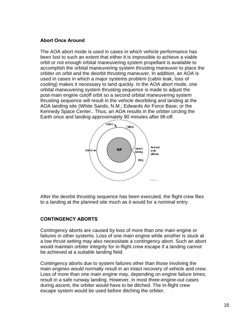
The AOA abort mode is used in cases in which vehicle performance hasbeen lost to such an extent that either it is impossible to achieve a viableorbit or not enough orbital maneuvering system propellant is available toaccomplish the orbital maneuvering system thrusting maneuver to place theorbiter on orbit and the deorbit thrusting maneuver. In addition, an AOA isused in cases in which a major systems problem (cabin leak, loss ofcooling) makes it necessary to land quickly. In the AOA abort mode, oneorbital maneuvering system thrusting sequence is made to adjust thepost-main engine cutoff orbit so a second orbital maneuvering systemthrusting sequence will result in the vehicle deorbiting and landing at theAOA landing site (White Sands, N.M.; Edwards Air Force Base; or theKennedy Space Center.. Thus, an AOA results in the orbiter circling theEarth once and landing approximately 90 minutes after lift-off.
After the deorbit thrusting sequence has been executed, the flight crew fliesto a landing at the planned site much as it would for a nominal entry.
CONTINGENCY ABORTS
Contingency aborts are caused by loss of more than one main engine orfailures in other systems. Loss of one main engine while another is stuck ata low thrust setting may also necessitate a contingency abort. Such an abortwould maintain orbiter integrity for in-flight crew escape if a landing cannotbe achieved at a suitable landing field.
Contingency aborts due to system failures other than those involving themain engines would normally result in an intact recovery of vehicle and crew.Loss of more than one main engine may, depending on engine failure times,result in a safe runway landing. However, in most three-engine-out casesduring ascent, the orbiter would have to be ditched. The in-flight crewescape system would be used before ditching the orbiter.
16
ABORT DECISIONS
There is a definite order of preference for the various abort modes. The typeof failure and the time of the failure determine which type of abort isselected. In cases where performance loss is the only factor, the preferredmodes would be ATO, AOA, TAL and RTLS, in that order. The mode chosenis the highest one that can be completed with the remaining vehicleperformance.
In the case of some support system failures, such as cabin leaks or vehiclecooling problems, the preferred mode might be the one that will end themission most quickly. In these cases, TAL or RTLS might be preferable toAOA or ATO. A contingency abort is never chosen if another abort optionexists.
The Mission Control Center-Houston is prime for calling these abortsbecause it has a more precise knowledge of the orbiter's position than thecrew can obtain from onboard systems. Before main engine cutoff, MissionControl makes periodic calls to the crew to tell them which abort mode is (oris not) available. If ground communications are lost, the flight crew hasonboard methods, such as cue cards, dedicated displays and displayinformation, to determine the current abort region.
Which abort mode is selected depends on the cause and timing of thefailure causing the abort and which mode is safest or improves missionsuccess. If the problem is a space shuttle main engine failure, the flight crewand Mission Control Center select the best option available at the time aspace shuttle main engine fails.
If the problem is a system failure that jeopardizes the vehicle, the fastestabort mode that results in the earliest vehicle landing is chosen. RTLS andTAL are the quickest options (35 minutes), whereas an AOA requiresapproximately 90 minutes. Which of these is selected depends on the timeof the failure with three good space shuttle main engines.
The flight crew selects the abort mode by positioning an abort mode switchand depressing an abort push button.
Updated: 05/11/1999
17

STS-96
Crew Profile Menu
Commander: Kent V. Rominger
During the flight, the Commander has onboard responsibility for thevehicle, crew, mission success and safety of flight. NASA EXPERIENCE: Selected by NASA in March 1992, Romingerreported to the Johnson Space Center in August 1992. He completedone year of training and is qualified for assignment as a pilot on futureSpace Shuttle flight crews. Rominger was initially assigned to worktechnical issues for the Astronaut Office Operations DevelopmentBranch. A veteran of three space flights, Rominger has logged over1,090 hours in space. He flew as pilot on STS-73 in 1995, STS-80 in 1996 and STS-85 in1997. Rominger is assigned to command the crew of Discovery on STS-96, a logistics andresupply mission for the International Space Station. Launch is targeted for May 1999.SPACE FLIGHT EXPERIENCE: STS-73 Columbia (October 20 to November 5, 1995) wasthe second United States Microgravity Laboratory mission. The mission focused onmaterials science, biotechnology, combustion science, the physics of fluids, and numerousscientific experiments housed in the pressurized Spacelab module. In completing his firstspace flight, Rominger orbited the earth 256 times, traveled over 6 million miles, and loggeda total of 15 days, 21 hours, 52 minutes and 21 seconds in space. STS-80 Columbia(November 19 to December 7, 1996) was a 17-day mission during which the crew deployedand retrieved the Wake Shield Facility (WSF) and the Orbiting Retrievable Far and ExtremeUltraviolet Spectrometer (ORFEUS) satellites. The free-flying WSF created a super vacuumin its wake and grew thin film wafers for use in semiconductors and other high-techelectrical components. The ORFEUS instruments, mounted on the reusable Shuttle PalletSatellite, studied the origin and makeup of stars. In completing his second space flight,Rominger orbited the earth a record 278 times, traveled over 7 million miles and logged 17days, 15 hours and 53 minutes in space. STS-85 (August 7-19, 1997) was a 12-day missionduring which the crew deployed and retrieved the CRISTA-SPAS satellite, operated theJapanese Manipulator Flight Demonstration (MFD) robotic arm, studied changes in theEarth's atmosphere and tested technology destined for use on the future InternationalSpace Station. The mission was accomplished in 189 Earth orbits, traveling 4.7 millionmiles in 11 days, 20 hours and 27 minutes. AUGUST 1998
Ascent Seating: Flight Deck - Port Forward Entry Seating: Flight Deck - Port Forward
18

Pilot: Rick D. Husband
The pilot assists the Mission Commander in controlling and operatingthe Shuttle. In addition, the pilot may assist in the deployment andretrieval of satellites utilizing the Shuttle's robot arm, and oftencoordinates the activities of astronauts conducting space walks orExtravehicular Activities. During STS-96, pilot Rick Husband will be a back-up EVA crewmember and also is the back-up robot arm operator during the spacewalks. NASA EXPERIENCE: Husband was selected as an astronaut candidate by NASA inDecember 1994. He reported to the Johnson Space Center in March 1995 to begin a yearof training and evaluation. Upon completion of training, Husband was named the AstronautOffice representative for Advanced Projects at Johnson Space Center, working on SpaceShuttle Upgrades, the Crew Return Vehicle (CRV) and studies to return to the Moon andtravel to Mars. Husband is assigned to pilot Discovery on STS-96, an 11-day logistics andresupply mission for the International Space Station. Launch is targeted for May 1999.
Ascent Seating: Flight Deck - Starboard Forward Entry Seating: Flight Deck - Starboard Forward
Mission Specialist 1: Tamara E. Jernigan
Dr. Jernigan will serve as the prime space walking crew member onSTS-96, designated EV 1, because of her striped space suit. She willalso be the first crew member to enter the International Space Stationthe day after she conducts her space walk with Dan Barry. Jerniganwill also serve as a backup to Ellen Ochoa for many proceduresinvolving the shuttle's robot arm, or remote manipulator system,except during the space walks when pilot Rick Husband is theback-up arm operator.
NASA EXPERIENCE: Selected as an astronaut candidate by NASA in June 1985, Dr.Jernigan became an astronaut in July 1986. Her assignments since then have included:software verification in the Shuttle Avionics Integration Laboratory (SAIL); operationscoordination on secondary payloads; spacecraft communicator (CAPCOM) in MissionControl for STS-30, STS-28, STS-34, STS-33, and STS-32; lead astronaut for flightsoftware development; Chief of the Astronaut Office Mission Development Branch; DeputyChief of the Astronaut Office. A veteran of four space flights, Dr. Jernigan has logged over1,277 hours in space. She was a mission specialist on STS-40 (June 5-14, 1991) andSTS-52 (October 22-November 1, 1992), was the payload commander on STS-67 (March2-18, 1995), and again served as a mission specialist on STS-80 (November 19 toDecember 7, 1996). Dr. Jernigan is currently the Assistant for Station to the Chief of theAstronaut Office, directing crew involvement in the development and operation of theStation. SPACE FLIGHT EXPERIENCE: STS-40 Spacelab Life Sciences (SLS-1) was adedicated space and life sciences mission aboard Space Shuttle Columbia. During thenine-day flight crew members performed experiments which explored how humans, animalsand cells respond to microgravity and readapt to Earth's gravity on return. Other payloadsincluded experiments designed to investigate materials science, plant biology and cosmicradiation. Mission duration was 218 hours, 14 minutes, 20 seconds. Landing was atEdwards Air Force Base, California. STS-52 was also launched aboard Space ShuttleColumbia. During the ten-day flight, the crew deployed the Italian Laser GeodynamicSatellite (LAGEOS) which will be used to measure movement of the Earth's crust, andoperated the U.S. Microgravity Payload 1 (USMP-1). Also, the Space Vision System (SVS),developed by the Canadian Space Agency, was tested by the crew using a small targetassembly which was released from the remote manipulator system. The SVS will be usedfor Space Station construction. In addition, numerous other experiments were performed bythe crew encompassing the areas of geophysics, materials science, biological research andapplied research for Space Station. Mission duration was 236 hours, 56 minutes 13seconds. Landing was at Kennedy Space Center, Florida. STS-67 Astro-2 mission aboard 19

seconds. Landing was at Kennedy Space Center, Florida. STS-67 Astro-2 mission aboardthe Space Shuttle Endeavour was the second flight of the Astro observatory, a uniquecomplement of three telescopes. During this record-setting 16-day mission, the crewconducted observations around the clock to study the far ultraviolet spectra of faintastronomical objects and the polarization of ultraviolet light coming from hot stars anddistant galaxies. Mission duration was 399 hours and 9 minutes. Landing was at EdwardsAir Force Base in California. On STS-80 the crew aboard Space Shuttle Columbiasuccessfully deployed and retrieved the Wake Shield Facility (WSF) and the OrbitingRetrievable Far and Extreme Ultraviolet Spectrometer (ORFEUS) satellites. The free-flyingWSF created a super vacuum in its wake and grew thin film wafers for use insemiconductors and other high-tech electrical components. The ORFEUS instruments,mounted on the reusable Shuttle Pallet Satellite, studied the origin and makeup of stars.Her two planned spacewalks were lost due to a jammed outer hatch on the airlock. Missionduration was a record breaking 423 hours, 53 minutes. MARCH 1998
Ascent Seating: Mid Deck - Port Entry Seating: Mid Deck - Port EV1
Mission Specialist 2: Ellen Ochoa
Dr. Ochoa will serve as the prime robot arm operator during STS-96,using the arm to maneuver Tammy Jernigan and Dan Barry for certaintasks during their space walk. Ochoa will also be the prime crewmember in charge of the tools to be used in Discovery's rendezvouswith the International Space Station and is responsible for activatingand deactivating the systems of the double Spacehab module in thecargo bay. In addition, Ochoa is the so-called "loadmaster" during theflight, responsible for the transfer of thousands of pounds of hardwareand logistical items from Discovery to the International Space Stationfor future use.
EXPERIENCE: As a doctoral student at Stanford, and later as a researcher at SandiaNational Laboratories and NASA Ames Research Center, Dr. Ochoa investigated opticalsystems for performing information processing. She is a co-inventor on three patents for anoptical inspection system, an optical object recognition method, and a method for noiseremoval in images. As Chief of the Intelligent Systems Technology Branch at Ames, shesupervised 35 engineers and scientists in the research and development of computationalsystems for aerospace missions. Dr. Ochoa has presented numerous papers at technicalconferences and in scientific journals. Selected by NASA in January 1990, Dr. Ochoabecame an astronaut in July 1991. Her technical assignments to date include flight softwareverification, crew representative for flight software and computer hardware development,crew representative for robotics development, testing, and training, Assistant for SpaceStation to the Chief of the Astronaut Office, directing crew involvement in the developmentand operation of the Station, and spacecraft communicator (CAPCOM) in Mission Control.A veteran of two space flights, Dr. Ochoa has logged over 484 hours in space. Dr. Ochoa isassigned to the crew of STS-96, a 10-day logistics and resupply mission for theInternational Space Station. Launch is targeted for May 1999. In April 1993, Dr. Ochoa flewas a Mission Specialist on STS-56, carrying ATLAS-2. During this 9-day mission the crew ofDiscovery conducted atmospheric and solar studies in order to better understand the effectof solar activity on the Earth's climate and environment. Dr. Ochoa used the RemoteManipulator System (RMS) to deploy and capture the Spartan satellite, which studied thesolar corona. Dr. Ochoa was the Payload Commander on the STS-66 AtmosphericLaboratory for Applications and Science-3 mission (November 3-14, 1994). ATLAS-3continues the series of Spacelab flights to study the energy of the Sun during an 11-yearsolar cycle and to learn how changes in the sun's irradiance affect the Earth's climate andenvironment. Dr. Ochoa used the RMS to retrieve the CRISTA-SPAS atmospheric researchsatellite at the end of its 8-day free flight.
20

Ascent Seating: Flight Deck - Center Aft Entry Seating: Flight Deck - Center Aft RMS
Mission Specialist 3: Daniel T. Barry
In addition to his role as one of two space walkers during the flight, Dr.Barry will be in charge of the operation of the various computers thecrew members will use. Barry will be one of three crew membersresponsible for the systems of the International Space Station duringthe docked phase of the flight, and will participate in a number ofsecondary experiments and technology demonstrations.
NASA EXPERIENCE: Selected by NASA in March 1992, Dr. Barryreported to the Johnson Space Center in August 1992. He completed one year of trainingand is qualified for assignment as a mission specialist on Space Shuttle flight crews. Dr.Barry has worked on primary payload development, the Shuttle Avionics IntegrationLaboratory (SAIL), portable computing issues for Space Shuttle, Chief of AstronautAppearances, and as a source board member for the NASA Space Biomedical ResearchInstitute (NSBRI). He flew on STS-72 in 1996, and has logged over 214 hours in Space,including a 6 hour, 9 minute spacewalk. Dr. Barry is assigned to STS-96 as an EVAcrewmember. STS-96 will be the first flight to dock to the International Space Station.Launch is targeted for May 1999. SPACE FLIGHT EXPERIENCE: STS-72 Endeavour(January 11-20, 1996) was a 9-day flight during which the crew retrieved the Space FlyerUnit (launched from Japan 10-months earlier), deployed and retrieved the OAST-Flyer, andDr. Barry performed a 6 hour, 9 minute spacewalk designed to demonstrate and evaluatetechniques to be used in the assembly of the International Space Station. Mission durationwas 142 Earth orbits, traveling 3.7 million miles in 214 hours and 41 seconds. AUGUST1998
Ascent Seating: Flight Deck - Starboard Aft Entry Seating: Mid Deck - Center EV2
21

Mission Specialist 4: Julie Payette
Payette will be the prime crew member in charge of Unity's systemswhile Discovery is docked to the International Space Station and willassist Valery Tokarev in monitoring Zarya's systems during the dockedphase of the mission. Payette is the lead crew member for any in-flightmaintenance of station systems or hardware, and will join ValeryTokarev for the swapout of battery voltage regulators in Zarya. She willalso be the prime choreographer for the space walk to be conducted byTammy Jernigan and Dan Barry. Payette is responsible for stowingequipment on the ISS and aboard Discovery, operating the Shuttle's robot arm for a camerasurvey, and will be in charge of the STARSHINE student science satellite.
Canadian Space Agency Astronaut. Ms. Payette was selected as an astronaut by theCanadian Space Agency (CSA) in June 1992 and underwent training in Canada. After basictraining, she worked as a technical advisor for the MSS (Mobile Servicing System), theCanadian contribution to the International Space Station. In 1993, Ms. Payette establishedthe Human-Computer Interaction (HCI) Group at the Canadian Astronaut Program andserved as a technical specialist on the NATO International Research Study Group (RSG-10)on speech processing (1993-1996). In preparation for a space assignment, Ms. Payettestudied Russian and logged over 120 hours of of reduced gravity flight time aboard variousparabolic aircraft (KC-135, T-33, Falcon-20, DC-9). In April 1996, Ms. Payette completed adeep-sea diving hard suit training program in Vancouver BC and was certified as aone-atmosphere diving suit operator. Ms. Payette obtained her captaincy on military jet atthe Canadian Air Force Base in Moose Jaw, Saskatchewan in February 1996. She hassince obtained her military instrument rating and continues to fly regularly with the trainingsquadron. Ms. Payette has logged more than 600 hours of flight time, including 150 hourson the Tutor CT-114 jet aircraft. NASA EXPERIENCE: Ms. Payette reported to the JohnsonSpace Center in August 1996 to begin mission specialist training. She completed initialastronaut training in April 1998 and was assigned to work technical issues for the AstronautOffice EVA/Robotics Branch. Ms. Payette is assigned as a mission specialist on the crew ofSTS-96 Atlantis, a 10-day logistics and resupply mission for the International Space Station.Launch is targeted for May 1999. AUGUST 1998
Ascent Seating: Mid Deck - Center Entry Seating: Flight Deck - Starboard Aft IV1
Mission Specialist 5: Valery Tokarev
Tokarev will join Tammy Jernigan as the first crew members to enterthe International Space Station on the fifth day of the flight and will beresponsible for Zarya's systems during the docked phase of the flight.He will be joined by Julie Payette for the swapout of battery voltageregulators aboard Zarya and will be involved in moving logistical itemsfrom Discovery to the ISS during six days of docked operations.
Valery Ivanovich Tokarev (Colonel, Russian Air Force) TestCosmonaut at the Yu.A. Gagarin Cosmonaut Training Center In 1987, Valery Tokarev wasselected to join the cosmonaut corps to fly the Buran spacecraft. Since 1994,he has servedas commander of a group of cosmonauts of aerospace systems and, since 1997, as a testcosmonaut for the Yuri A. Gagarin Cosmonaut Training Center. SEPTEMBER 1998
Ascent Seating: Mid Deck - Starboard Entry Seating: Mid Deck - Starboard
22

STS-96
Flight Day Summary
DATE TIME (EST) DAY MET EVENT
05/27/99 6:48:00 AM 1 000/00:00 Launch Time
05/27/99 7:32:00 AM 1 000/00:44 OMS 2
05/27/99 9:49:00 AM 1 000/03:01 NC-1
05/27/99 11:48:00 AM 1 000/05:00 Flight Day 1 Sleep
05/27/99 7:48:00 PM 2 000/13:00 Flight Day 2 Wake
05/27/99 10:48:00 PM 2 000/16:00 SHAB Activation
05/27/99 10:50:00 PM 2 000/16:02 NC-2
05/27/99 11:53:00 PM 2 000/17:05 EMU Checkout
05/28/99 2:35:00 AM 2 000/19:47 NPC
05/28/99 3:18:00 AM 2 000/20:30 RMS C/O
05/28/99 4:33:00 AM 2 000/21:45 Waste Dump
05/28/99 7:16:00 AM 2 001/00:28 NC 3
05/28/99 8:03:00 AM 2 001/01:15 10.2 Cabin Depress
05/28/99 9:48:00 AM 2 001/03:00 Flight Day 2 Sleep
05/28/99 5:18:00 PM 3 001/10:30 Flight Day 3 Wake
05/28/99 5:42:00 PM 3 001/10:54 FGB OSK Build
05/28/99 7:16:00 PM 3 001/12:28 NH
05/28/99 8:01:00 PM 3 001/13:13 NC 4
05/28/99 9:33:00 PM 3 001/14:45 Ti
05/28/99 10:38:00 PM 3 001/15:50 SSC C/O
05/28/99 10:48:00 PM 3 001/16:00 SK at 170 ft (estimated)
05/28/99 10:53:00 PM 3 001/16:05 EPCS Setup
05/28/99 11:04:00 PM 3 001/16:16 +Rbar Arrival
05/28/99 11:31:00 PM 3 001/16:43 -Rbar Arrival
05/29/99 12:16:00 AM 3 001/17:28 Push from 30 ft
05/29/99 12:21:00 AM 3 001/17:33 Contact
05/29/99 12:41:00 AM 3 001/17:53 Docking complete
05/29/99 3:13:00 AM 3 001/20:25 Early Ingress PMA 2
05/29/99 3:28:00 AM 3 001/20:40 CBM Controller Removal
05/29/99 3:43:00 AM 3 001/20:55 Node 1 Powerup
05/29/99 4:28:00 AM 3 001/21:40 Early Egress PMA 2
05/29/99 9:48:00 AM 3 002/03:00 Flight Day 3 Sleep
05/29/99 5:48:00 PM 4 002/11:00 Flight Day 4 Wake
05/29/99 6:48:00 PM 4 002/12:00 Node 1 IMV Valve Reconfig
23

05/29/99 7:48:00 PM 4 002/13:00 EVA Prep
05/29/99 9:28:00 PM 4 002/14:40 Early Comm Ant Survey via RMS
05/29/99 11:03:00 PM 4 002/16:15 EVA 1 A/L Egress
05/30/99 4:58:00 AM 4 002/22:10 EVA 1 A/L Ingress
05/30/99 5:38:00 AM 4 002/22:50 OSVS Target Survey
05/30/99 9:48:00 AM 4 003/03:00 Flight Day 4 Sleep
05/30/99 5:48:00 PM 5 003/11:00 Flight Day 5 Wake
05/30/99 7:38:00 PM 5 003/12:50 PMA 2 Ingress
05/30/99 7:48:00 PM 5 003/13:00 Simo Dump
05/30/99 7:48:00 PM 5 003/13:00 SHAB Config
05/30/99 8:33:00 PM 5 003/13:45 Node Ingress
05/30/99 8:58:00 PM 5 003/14:10 PMA 1 Ingress
05/30/99 9:08:00 PM 5 003/14:20 FGB Ingress
05/30/99 10:03:00 PM 5 003/15:15 Bar Code Labels Installation
05/30/99 10:03:00 PM 5 003/15:15 Rack Pin Install
05/30/99 10:08:00 PM 5 003/15:20 CWC Initial S/U, Bag 1 of 7
05/30/99 10:33:00 PM 5 003/15:45 First ZSR Installation
05/30/99 10:38:00 PM 5 003/15:50 MIRTS Install (Batt Block 4)
05/30/99 11:03:00 PM 5 003/16:15 Second ZSR Installation
05/30/99 11:33:00 PM 5 003/16:45 Early Comm IFM Start
05/31/99 12:03:00 AM 5 003/17:15 ZSR Label Installation
05/31/99 12:08:00 AM 5 003/17:20 MIRTS Install (Batt Blocks 5 & 6)
05/31/99 12:13:00 AM 5 003/17:25 Transfer Ops Begin
05/31/99 12:23:00 AM 5 003/17:35 14.7 Cabin Repress
05/31/99 1:38:00 AM 5 003/18:50 MIRTS C/O (Batt Block 3)
05/31/99 1:58:00 AM 5 003/19:10 Radiation Monitors Deploy
05/31/99 2:03:00 AM 5 003/19:15 Node 1 Hatch Inspection
05/31/99 2:03:00 AM 5 003/19:15 Acoustic Sample, 1 of 2
05/31/99 2:38:00 AM 5 003/19:50 Muffler Install, Pt 1 of 2
05/31/99 3:58:00 AM 5 003/21:10 CWC Fill Init, Bag 2 of 7
05/31/99 5:13:00 AM 5 003/22:25 Formaldehyde Mon Dply
05/31/99 5:48:00 AM 5 003/23:00 PAO Event-CDR, MS1, MS3
05/31/99 9:18:00 AM 5 004/02:30 Flight Day 5 Sleep
05/31/99 5:18:00 PM 6 004/10:30 Flight Day 6 Wake
05/31/99 8:08:00 PM 6 004/13:20 MIRTS Install (Batt 1 & 2)
05/31/99 8:18:00 PM 6 004/13:30 CWC Fill Init, Bag 3 of 7
05/31/99 8:18:00 PM 6 004/13:30 Transfer Ops Begin
05/31/99 9:43:00 PM 6 004/14:55 Muffler Install, Pt 2 of 2
05/31/99 11:08:00 PM 6 004/16:20 Acoustic Sample, 2 of 2
06/01/99 1:18:00 AM 6 004/18:30 PAO Event-CDR, MS5
06/01/99 2:13:00 AM 6 004/19:25 CWC Fill Init, Bag 4 of 7
24

06/01/99 2:28:00 AM 6 004/19:40 DTO 700-14 Ops 2 Test
06/01/99 3:03:00 AM 6 004/20:15 VRA Initial Setup
06/01/99 5:13:00 AM 6 004/22:25 Formaldehyde Mon Retreive
06/01/99 5:33:00 AM 6 004/22:45 Simo Dump
06/01/99 8:48:00 AM 6 005/02:00 Flight Day 6 Sleep
06/01/99 4:48:00 PM 7 005/10:00 Flight Day 7 Wake
06/01/99 7:08:00 PM 7 005/12:20 PAO Event-CDR, MS4
06/01/99 8:03:00 PM 7 005/13:15 Transfer Ops Begin
06/01/99 8:13:00 PM 7 005/13:25 CWC Fill Init, Bag 5 of 7
06/01/99 8:58:00 PM 7 005/14:10 VRA Science Activation
06/01/99 11:13:00 PM 7 005/16:25 VRA Sample Pair 1
06/01/99 11:58:00 PM 7 005/17:10 Crew Conference
06/02/99 1:38:00 AM 7 005/18:50 VRA Sample Pair 2
06/02/99 2:03:00 AM 7 005/19:15 CWC Fill Init, Bag 6 of 7
06/02/99 4:48:00 AM 7 005/22:00 VRA Sample Pair 3
06/02/99 5:23:00 AM 7 005/22:35 PAO Event-CDR, PLT, MS2
06/02/99 8:48:00 AM 7 006/02:00 Flight Day 7 Sleep
06/02/99 4:48:00 PM 8 006/10:00 Flight Day 8 Wake
06/02/99 7:48:00 PM 8 006/13:00 Transfer Ops Begin
06/02/99 7:48:00 PM 8 006/13:00 VRA Sample Pair 4
06/02/99 7:48:00 PM 8 006/13:00 N1 Hatch Adjustment
06/02/99 7:48:00 PM 8 006/13:00 DTO 1214
06/02/99 7:48:00 PM 8 006/13:00 Rack Pin Locate
06/02/99 8:48:00 PM 8 006/14:00 FGB Dust Filter
06/02/99 9:38:00 PM 8 006/14:50 SDS Valves Troubleshoot
06/02/99 9:48:00 PM 8 006/15:00 CWC Fill Init, Bag 7 of 7
06/02/99 9:48:00 PM 8 006/15:00 FGB Harmful Cart Rplc
06/02/99 10:13:00 PM 8 006/15:25 VRA Sample Pair 5
06/02/99 11:48:00 PM 8 006/17:00 O2 Repress
06/03/99 1:03:00 AM 8 006/18:15 VRA Sample Pair 6
06/03/99 1:23:00 AM 8 006/18:35 FGB PGO Egress
06/03/99 2:28:00 AM 8 006/19:40 FGB GA Egress
06/03/99 2:33:00 AM 8 006/19:45 VRA Deact
06/03/99 3:13:00 AM 8 006/20:25 PMA 1 Egress
06/03/99 3:48:00 AM 8 006/21:00 Node 1 Egress
06/03/99 4:08:00 AM 8 006/21:20 PMA 2 Egress
06/03/99 4:18:00 AM 8 006/21:30 Reboost
06/03/99 4:38:00 AM 8 006/21:50 VEST/PMA 2 Depress
06/03/99 5:18:00 AM 8 006/22:30 ISS Egress Complete
06/03/99 8:48:00 AM 8 007/02:00 Flight Day 8 Sleep
06/03/99 9:48:00 AM 8 007/03:00 NCS TFL U/L
25

06/03/99 11:48:00 AM 8 007/05:00 NCS S/W Patch U/L
06/03/99 1:48:00 PM 8 007/07:00 NCS DBL U/L
06/03/99 3:48:00 PM 9 007/09:00 Flight Day 9 Wake
06/03/99 6:37:00 PM 9 007/11:49 Undock
06/03/99 8:08:00 PM 9 007/13:20 Final Sep
06/03/99 8:48:00 PM 9 007/14:00 FGB OSK Build
06/03/99 9:03:00 PM 9 007/14:15 Simo Dump
06/03/99 9:18:00 PM 9 007/14:30 PILOT Training
06/03/99 9:43:00 PM 9 007/14:55 Space Flight Awareness
06/04/99 12:48:00 AM 9 007/18:00 Off Duty
06/04/99 8:48:00 AM 9 008/02:00 Flight Day 9 Sleep
06/04/99 4:48:00 PM 10 008/10:00 Flight Day 10 Wake
06/04/99 7:48:00 PM 10 008/13:00 FCS C/O & RCS H/F
06/04/99 7:48:00 PM 10 008/13:00 SHAB Stow
06/04/99 9:13:00 PM 10 008/14:25 Cabin Stow
06/04/99 9:53:00 PM 10 008/15:05 MAGR OPS3 GPS Test
06/04/99 11:18:00 PM 10 008/16:30 PAO Taped Message
06/05/99 12:48:00 AM 10 008/18:00 D/O Brief
06/05/99 3:11:00 AM 10 008/20:23 Starshine Deploy
06/05/99 4:03:00 AM 10 008/21:15 L-1 Comm Check, part 1 of 2
06/05/99 5:03:00 AM 10 008/22:15 L-1 Comm Check, part 2 of 2
06/05/99 5:33:00 AM 10 008/22:45 Ku-antenna stow
06/05/99 8:48:00 AM 10 009/02:00 Flight Day 10 Sleep
06/05/99 4:48:00 PM 11 009/10:00 Flight Day 11 Wake
06/06/99 2:21:00 AM 11 009/19:33 Deorbit Tig
06/06/99 3:25:00 AM 11 009/20:37 Landing at KSC
Updated: 05/20/1999
26

STS-96
Rendezvous
Docking Mechanisms
Overview
ISS Docking Mechanism plans for Discovery, other Shuttles and this firstlogistics mission call for Discovery to dock at the ISS on Day 3 and remainthere for six days. The Shuttle’s external airlock will be connected to Unity’sPressurized Mating Adapter (PMA) 2 using an interlocking systemdesigned in Russia. It is termed an Androgynous Peripheral Attach System.Discovery’s crew will control PMA-2’s docking mechanism from thecockpit.
27

Pressurized Mating Adapters
Two PMAs are attached to Unity, one at each end. They providepassageways for crew, equipment and supplies. They also feature dockingmechanisms for space shuttles at one end and Zarya at the other.
Because they are pressurized, heated and supplied with hand-hold grips,the 8-ft-long, tunnel-like PMAs permit shirt-sleeved crews to pass betweenDiscovery and the ISS.
Androgynous Peripheral Attach System
A structural ring, a movable ring, alignment guides, latches, hooks,dampers and fixers are integrated to form the Androgynous PeripheralAttach System. It mates with an exact copy, and each can act as thepassive or active half.
During docking, the active half’s capture ring extends outward from thestructural ring toward the passive half. Upon contact, the system dampensout any relative motion between the docking vehicles. Once that isaccomplished, the capture ring aligns the two vehicles. It is then retracted with the passive ring still attached. Twenty-fourstructural hooks snug the connection down to form an airtight seal.
History/Background
The Androgynous Peripheral Attach System’s technological roots reachback to the Apollo-Soyuz and Shuttle-Mir missions. The System is built byMoscow-based RSC-Energia.
Updated: 05/14/1999
28

STS-96
Rendezvous
Rendezvous and Docking
Overview
Discovery’s rendezvous and docking with the International Space Stationactually begins with the precisely timed launch of the shuttle on a course forthe station. During the first two days of the mission, periodic engine firingswill gradually bring Discovery to a point about eight nautical miles behind thestation, the starting point for a final approach to the station.
Terminal Phase
About three hours before the scheduled docking time on Flight Day Three,Discovery will reach the point about eight nautical miles behind the ISS. Atthat time, Discovery's jets will be fired in a Terminal Phase Initiation (TI)burn to begin the final phase of the rendezvous. Discovery will close thefinal eight nautical miles to the station during the next orbit. As Discoverycloses in, the shuttle’s rendezvous radar system will begin tracking thestation and providing range and closing rate information to the crew.
29

As Discovery begins to close in on the station, flight controllers willcommand the station to the docking orientation, perpendicular to the Earth'ssurface with the Unity module pointed toward space and Zarya towardEarth. For Discovery's final approach, the solar panels on the station will be"feathered" to have their edge facing the shuttle. Also, when within about1,000 feet of the station, Commander Kent Rominger will use Discovery'ssteering jets in a mode called "Low Z," a mode that fires jets offset ratherthan pointed directly at the station to control the shuttle's approach. This jetmode together with the solar panel's feathering prevent exhaust from shuttlejets from flexing and overstressing the station's solar panels.
Proximity Operations
As Discovery reaches close proximity to the station, the Trajectory ControlSensor, a laser ranging device mounted in the shuttle payload bay, willsupplement the shuttle’s onboard navigation information by supplyingadditional data on the range and closing rate. As Discovery closes in, theshuttle will have the opportunity for several small successive engine firingsto fine-tune its approach using its onboard navigation information. AsDiscovery moves to within about a half-mile of the station, Rominger willtake over manual control of the shuttle's approach, flying the spacecraftfrom the aft flight deck and monitoring the approach through the rear andoverhead windows.
30

Rominger will slow Discovery's approach and fly to a point about 500 feetdirectly below the station, from which he will begin a half-circle of thestation. During the rendezvous, Rominger will be assisted by Pilot RickHusband in controlling Discovery's approach. Mission Specialists TammyJernigan and Ellen Ochoa also will play key roles in the rendezvous, withJernigan operating the shuttle's docking mechanism and Ochoa assistingwith the rendezvous navigation. The crew will use a handheld laser pointedthrough the shuttle windows to provide supplemental information on thestation's range and closing rate.
Rominger will fly Discovery to cross about 350 feet in front of the station andthen continue to reach a point about 250 feet directly above the station. Hewill stop Discovery and then slowly descend toward the station to a pointabout 170 feet away from it. At approximately 170 feet distant, Rominger willhold Discovery's position for about a half-hour to allow the station to movewithin range of Russian communications stations. Also at this time, Jerniganwill power up the docking mechanism and prepare it for contact and capturewith the station. A day ahead of the rendezvous, the docking mechanism isscheduled to be checked out and its docking ring extended.
Final Approach
Once the station is in communications with Russia and flight controllershave confirmed it is in the proper configuration for docking, Rominger willbegin the final approach.
Using the view from a centerline camera fixed in the center of Discovery'sdocking mechanism, Rominger will precisely align the shuttle mechanismwith the docking mechanism on Unity's conical mating adapter as heapproaches. At a distance of about 30 feet, Rominger will stationkeepmomentarily to adjust the alignment, if necessary.
Docking
For Discovery's docking, Rominger will maintain the shuttle's speed relativeto the station at about one-tenth of a foot per second, and keep the dockingmechanisms aligned to within three inches of one another. As Discoverymoves to within 25 feet, Rominger will switch the shuttle steering jets backto normal mode from "Low Z" to provide better control of Discovery for thefinal docking.
When Discovery makes contact with the station, latches will automaticallyattach the two spacecraft together. Immediately after Discovery docks, theshuttle's steering jets will be deactivated and ground controllers willcommand off the station's steering jets to reduce the forces acting at the
31

docking interface. Shock absorber-type springs in the docking mechanismwill dampen any relative motion between the shuttle and the station.
Once relative motion between the spacecraft has been stopped, Jerniganwill command the docking ring on Discovery's mechanism to retract andclose latches in the mechanism to firmly secure the shuttle to the station.Once the two vehicles are firmly secured, the shuttle’s steering jets will bereactivated to control both spacecraft for the duration of the dockedoperations.
Updated: 05/11/1999
32

STS-96
Rendezvous
Undocking, Separation and Fly-Around
Overview
Once Discovery is ready to undock, the initial separation will be performedby springs in the docking mechanism that will gently push the shuttle awayfrom the station. Both Discovery and the station’s steering jets will be shutoff to avoid any inadvertent firings during this initial separation.
Once the docking mechanism’s springs have pushed Discovery away to adistance of about two feet, when the docking devices will be clear of oneanother, Husband will turn the shuttle's steering jets back on in "Low Z"mode and fire them to begin very slowly moving away. From the aft flightdeck, Pilot Rick Husband will manually control Discovery within a tightcorridor as he separates from the ISS, essentially the reverse of the taskperformed by Commander Kent Rominger when Discovery docked.
Discovery will continue away to a distance of about 450 feet, whereHusband will begin the close flyaround of the station, first crossing a pointdirectly behind, then directly underneath and then again above the station.If Discovery’s propellant reserves allow it, Husband will circle the stationtwice as the crew records views of the exterior with still photography andvideo. As Discovery crosses directly above the station for the second time,Husband will fire Discovery's jets to perform a final separation. Theseparation firing will put Discovery on a course that will have it pass about ahalf-mile behind the station and then about a mile and a half below thestation before moving ahead of it with constantly increasing distance.
Updated: 05/11/1999
33

STS-96
EVAs Space Walk to Install U.S., Russian Crane Systems
Overview
Astronauts Tammy Jernigan and Daniel Barry will conduct a six-hour spacewalk on flight day four to install crane systems that will be used on futuremissions to assist in assembly and transfer operations. The two astronautswill be assisted by Flight Engineer Ellen Ochoa, who will operate theShuttle’s robotic arm from inside Discovery.
Getting Ready
Preparations for the space walk begin early in the mission, on flight day two,with the checkout of the space suits, also called extravehicular mobilityunits, or EMUs. Later that day, the air pressure in the crew cabin will bereduced from the standard operating pressure at 14.7 psi to 10.2 psi inorder to gradually condition the astronauts to an atmospheric environmentmore closely resembling that of the space suits, themselves, which operateat 4.3 psi. This technique reduces the time required for the astronauts to
34

"prebreathe" pure oxygen so that nitrogen may be cleansed from theirbloodstream to prevent a condition commonly called the "bends." Theastronauts will prepare their EVA tools and review procedures for theirinstallation operation on the third day of the mission.
The Space Walk
On flight day four, Jernigan and Barry will don their space suits, pre-breathepure oxygen to cleanse the remaining nitrogen from their blood streams,and exit the Orbiter into the payload bay for six hours of preparation,installation and cleanup. Jernigan, designated "EV1" will exit the airlockfirst and, after configuring tethers for the start of the space walk, will bejoined by Barry, designated "EV2." Jernigan will be visibly distinguished bya red stripe around the legs on her space suit.
Preparations will include the placement of a work station and portable footrestraints into position for the installation of an American-built crane, calledthe ORU Transfer Device, or OTD, and the Russian-built crane called Strela(Russian, for "arrow"). Installation of the OTD and Strela are estimated totake about 1 hour each.
Ready to begin the installation work, Jernigan will fix her boots to a footrestraint on the end of the Shuttle's robotic arm, and Ochoa will maneuverher from a foot restraint at Pressurized Mating Adapter (PMA-1) to theIntegrated Cargo Carrier (ICC). PMA-1 is a passageway between Unity andZarya, and the ICC is a flatbed pallet attached in Discovery's payload bay.
Jernigan will meet Barry on the Integrated Cargo Carrier, where they willretrieve the small, 209-pound U.S. OTD. While holding the crane, Jerniganwill be transported back to PMA-1. Barry will join her to attach the crane toan EVA worksite fixture on the PMA.
The two will return to the Integrated Cargo Carrier and retrieve the165-pound operator post and 33-pound grapple fixture adapter plate for theRussian crane, Strela. They will assemble those pieces on one of the twoPMA-2 grapple fixtures. PMA-2 connects the Shuttle external airlock toUnity.
Strela is an updated version of the crane used on Mir. It will primarily beused for Science Power Platform operations. Assembly of thethree-metric-ton capacity crane will be completed during this year's secondISS logistics mission. A 45-ft. telescopic boom will then be added to theoperator post, and the completed assembly will be moved to a grapplefixture on Zarya.
The astronauts will then return to the ICC to retrieve two portable footrestraints and transfer them into PMA-1. They will return to the IntegratedCargo Carrier, one last time, to remove three tool and hardware bags andthree additional pieces of EVA support equipment from the SPACEHAB
35
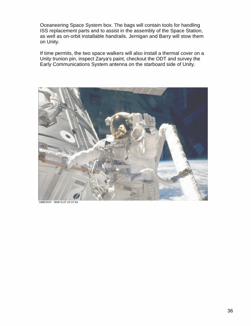
Oceaneering Space System box. The bags will contain tools for handlingISS replacement parts and to assist in the assembly of the Space Station,as well as on-orbit installable handrails. Jernigan and Barry will stow themon Unity.
If time permits, the two space walkers will also install a thermal cover on aUnity trunion pin, inspect Zarya's paint, checkout the ODT and survey theEarly Communications System antenna on the starboard side of Unity.
36

Time Event Prime Backup
0:00 Airlock Egress TamaraJernigan
Daniel Barry
00:30 Post Depress/Egress; andset-up for EVA activitiesin Payload Bay
TamaraJernigan
Daniel Barry
01:30 Crane Setup by RMSOperator Ochoa; CraneRemoval and Installationby Jernigan & Barry
TamaraJernigan
Daniel Barry
02:30 STRELA Set up by RMSOperator Ochoa; STRELARemove and Install byJernigan and Barry
TamaraJernigan
Daniel Barry
03:45 IAPFR Pre-Retrieve andInstall with RMS; IAPFRRemove by EV1, DockingTarget Install by EV2
TamaraJernigan
Daniel Barry
04:30 Logistics Bags Retrieveby RMS Operator; ToolBag Install by EV1 andEV2; Photo Survey byEV1
TamaraJernigan
Daniel Barry
05:30 Foot Restraint Install, andPayload Bay Clean Up
TamaraJernigan
Daniel Barry
06:15 Airlock Ingress andRe-press (approx. 20minutes)
TamaraJernigan
Daniel Barry
06:35 EVA Conclusion TamaraJernigan
Daniel Barry
Updated: 05/14/1999
37

STS-96
Payloads
Cargo TransferSpaceHab
Prime: Julie Payette
Overview
Mission Specialists working in the pressurized, shirtsleeves environmentprovided by SPACEHAB are tasked with moving some 750 items to the ISSfrom the cargo carrier’s racks, lockers and other stowage facilities. Anumber of those items are being stowed aboard the Station for use bycrews on future missions, beginning with the addition of Russia’s ServiceModule:
38

Items ISS Mission /Year Planned ISS Location
Computers, printers, 2R Russian Service Module / 1999 Zaryacables
Vacuum access 3A Integrated Truss Z1 / 1999 Unityjumper, charcoalcanisters, adapters
Oxygen canisters 4A Integrated Truss P6 / 1999 Unity
Vacuum access 5A US Laboratory Module / 2000 Unityjumper
Russian hardware that will be placed on the ISS during STS-96 includes:
· Life support systems replacement spares· Sanitary and hygienic equipment· Medical support equipment· On-board computer system replacement parts· Maintenance repair kits· Base unit and related components of the Strela ("Arrow") crane· Zarya sound damping kits· MIRT repair kits
Priorities
Logistics experts for this mission developed a categorical priority system formoving cargo that puts the highest value on ensuring the safe entry and exitof the crew members as they move between the shuttle and the ISS. Thesepriorities were set in accordance with the most mission critical to the least,while accounting for what would be left undone were the mission to beterminated earlier than planned.
Examples from each category are shown below, starting with the highestpriority.
1. Ingress/safety· ISS oxygen communication assembly· Atmosphere sampling bottles· Charcoal filter analyzer element· Zarya muffler [acoustic damping] hardware
39

2. Critical spares · MIRTs · Sequential shunt unit · Common Berthing Mechanism seal patch kits · Early communication command telemetry processor
3. Incremental assembly · Tools and power equipment · Tethers and related gear · Photo-TV cameras, film, tape · Space suits and associated garments, equipment
4. Crew health maintenance · Medical support equipment · Cardiorecorder · Audio dosimeter biobag · Formaldehyde monitor kit
5. Pre-position for future missions
6. Resupply · 2A recovery hardware · Driver drill charger kit · Braycote lubricant · Emergency exit decal
7. Spares/non-assembly equipment · IMAX 3D movie production hardware, accessories · Crew provisions · Clothing · Sleeping bags
8. Detailed test objectives · Velcro ties · Single-sided tape · Strain gage extension cables · Flex hose assembly
Cargo Handling
Despite the virtual weightlessness in which the astronauts will work, movingthe SPACEHAB's cargo won’t be easy. In carefully choreographedmovements not unlike those of research divers retrieving specimens from acoral reef, the Mission Specialists will ease each cargo item out of itsindividual location and push or pull it to its destination.
40

En route, the items must be taken through Discovery’s cargo bay tunnel,negotiated around a right-angle turn and into Pressurized Mating Adapter 2,and either deposited in Unity or pushed on into Zarya.
Additional Tasks
If time permits, additional tasks will be performed during the spacewalk andinternal transfers.
Space-walking astronauts Jernigan and Barry may have time to survey, forinstance, discoloration on Unity, the starboard omnidirectional antenna forthe ISS Early Communications System, and the paint on Zarya.
Mission Specialists inside will try to find the time to pressure-check anitrogen line, inspect Unity’s forward and aft hatch mechanisms and adjustthem if necessary, and trouble-shoot a sample delivery system valve. Ifthere is sufficient shuttle propellant following Discovery’s undocking from theISS, a fly-around visual inspection will be performed prior to de-orbit andlanding.
Updated: 05/11/1999
41

STS-96
Payloads
Integrated Cargo Carrier
Payload Bay
3050 lbs. lbs.
Prime:
Backup:
Overview
The Integrated Cargo Carrier is an unpressurized flat bed pallet and keelyoke assembly housed in Discovery's payload bay. Constructed ofaluminum, it is eight feet long, 15 feet wide and 10 inches thick and has thecapability to carry cargo on both faces of the pallet, both atop and below.
42

During STS-96, the ICC will carry the U.S. space walkers' crane, which iscalled the OTD for Orbital Replacement Unit Transfer Device. The OTDweighs 209 pounds and will be mounted to the exterior of Unity during aspace walk by astronauts Tammy Jernigan and Dan Barry. It also will carry198 pounds of parts for the Russian Strela crane which will be stowed onthe exterior of Pressurized Mating Adapter 2 (PMA-2)by Jernigan and Barry.
Also mounted to the ICC, is the Spacehab-Oceaneering Space System Box(SHOSS), which is designed to carry up to 400 pounds of space-walkingtools and flight equipment to assist astronauts during ISS assembly.
The ICC provides sufficient surface area in the cargo bay to carryapproximately 3,000 pounds of cargo which would otherwise have to becarried in the Shuttle's cabin.
The ICC will be used by astronauts throughout the construction of theSpace Station as it transports hardware from locations on the station'sexterior to work sites on the truss assemblies.
Updated: 05/19/1999
43

STS-96
Payloads
Integrated Vehicle Health Monitoring HEDS TechnologyDemonstration 2
Payload Bay
254 lbs. lbs.
Prime: Rick Husband
Overview
This is the second of two planned flights of the IVHM HTD, an experimentdesigned to evaluate the feasibility of using modern commercial sensors tomonitor the health of space shuttle systems during flight in order to reduceground processing of NASA's fleet of orbiters. IVHM HTD-1 was flown onSTS-95 in October-November of 1998.
Shuttle processing currently involves the verification of thousands ofrequirements to determine the health of shuttle systems. In early 1997,NASA studied these requirements to determine if it could reduce theprocessing time and increase vehicle safety. NASA found that groundprocessing (planned and unplanned) could potentially be reduced 15 to20%. Planned work could be reduced by implementing a system withpredictive capabilities to monitor subsystem health in real time during flightand by extending the service life of life-limited components. Unplannedwork could be reduced by improving visibility of system health andstreamlining problem isolation.
IVHM is essentially an advanced form of a traditional vehicleinstrumentation system, which consists of sensors (pressure, temperature,voltage, strain, acceleration, etc.), wiring, signal conditioning devices,multiplexing devices, and recording devices. But an IVHM system goes astep further by providing the capability to process data instead of merelyrecording data. This allows an onboard trend analysis that could detectsystem degradation and control in-flight systems checkout in addition toallowing more efficient system servicing and checkout on the ground.
During the terminal launch countdown, an IVHM data stream is transmittedto the Launch Control Center for processing and viewing. Approximately 10
44

seconds before takeoff, the IVHM processor autonomously beginsrecording data. Data is recorded during ascent and during predefinedperiods on orbit. The recorded data is dumped to a ground system after themission.
On STS-96, the experiment will be activated during prelaunch cryogenicpropellant servicing. The pilot will deactivate the HTD about one hour afterlaunch. The crew will activate the experiment for one hour each day duringthe mission.
The IVHM HTD-2 experiment package consists of an air transport rack fordata acquisition and processing and two remote health nodes mounted on agetaway special beam in the orbiter payload bay. The ATR and RHNs areconnected by cables to 120 sensors in the orbiter aft crew compartmentand payload bay.
One of the technologies to be demonstrated is microelectromechanicalsensing for detecting the presence of hazardous gas and sensing pressurein vacuum-jacketed lines in the orbiter's cryogenic distribution system. Othertechnology demonstrations include Bragg-Grating fiber-optic sensing forhazardous gas detection and structural strain/temperature determination,thermal flow meter leak detection, accelerometers for space shuttle mainengine pump vibration sensing, VME bus architecture, and flash cardmemory.
The HTDs will also provide data on the performance of commercialcomputing products, such as a VME bus architecture and ATR chassis, andon the effects of radiation and heat on commercial and military VMEhardware.
The focus of IVHM HTD-2 is to determine the health of selected functions ofthe orbiter's main propulsion system, main engines, and power reactantstorage and distribution system. The technologies to be developed includeBragg-Grating fiber-optic sensors for hydrogen, strain, and temperaturesensing and smart sensors for hydrogen, oxygen, and pressure sensing.IVHM HTD-2 will also evaluate distributed data acquisition by the remotehealth nodes with fiber data distributed interface communication and alightweight, low-power microelectronic hardware platform; real-timeinformation processing of space shuttle main engine pump vibration;solid-state data storage; and advanced control room equipment andapplications.
A complete flight IVHM system consists of advanced lightweight, low-powersensors; distributed data acquisition and processing; real-time informationprocessing, including diagnostics, prognostics, and vehicle autonomy forcontrol or suggested action; and advanced solid-state, high-density datastorage. A complete ground IVHM system consists of improved controlroom architectures and automated ground support equipment. This
45

experiment will advance the development of a subset of a complete IVHMsystem.
History/Background
The IVHM HTD experiments are part of NASA's Human Exploration andDevelopment of Space enterprise. HEDS is pursuing answers to myriadresearch and engineering questions that must be answered as humanslearn to live and work in space. The goals of the HEDS enterprise are toexplore the solar system, use the environment of space to expand scientificknowledge, provide safe and affordable human access to space, and enrichlife on Earth through space.
Benefits
The IVHM HTDs are providing data on the performance of advancedsensing technologies and commercial products which may be useful inreducing the cost and time associated with processing the space shuttle,streamlining problem troubleshooting, and improving NASA's awareness ofshuttle systems during operation. Technologies and products that are foundto be useful will be incorporated into an IVHM system for the shuttle. Thedata from these experiments may also be used to benefit other programs,such as liquid flyback boosters, X vehicles, the crew return vehicle, andlunar/Mars missions.
Updated: 05/11/1999
46

STS-96
Payloads
MIRTs ChangeoutSpaceHab
Prime: Julie Payette
Backup: Valery Tokarev
Overview
On Flight Days 5 and 6, astronaut Julie Payette and Cosmonaut ValeryIvanovich Tokarev will replace all 18 of the battery charge/discharge unitsthat support Zarya’s six nickel-cadmium batteries. Known by the Russianacronym "MIRTs," they are thought to be responsible for voltage problemsfirst detected in January.
MIRTs are part of a system that indicates the level of charge for each ofZarya’s batteries and, in turn, dictates when the onboard charging systemwill begin to taper-off the power supply to each.
47

Flight controllers have been working around the problem by cycling thebatteries, fully charging, and then fully discharging them every week. Thisprocedure resets the charge indication and maintains the batteries at peakperformance. It appears that when Zarya’s MIRTs measure the cumulativecharge or amp-hour readings of each battery, they introduce a slight error ina compensation factor and thus prevent full charge/discharge cycles fromoccurring.
Replacement of the units -- they measure 5.9 x 4.7 x 3 inches and weigh1.43 pounds -- may reduce the need for weekly cycling, resulting in betterlong-term battery performance and additional backup equipment capabilitiesfor the ISS. Payette and Tokarev were trained for this part of the mission inmid-March at the Gagarin Cosmonaut Training Center at Star City outsideMoscow, where a full-scale Zarya mock-up is located, and will followprocedures jointly developed by engineers at Mission Control CenterMoscow and Mission Control Center-Houston.
The MIRTs are located under Zarya’s floor panels.
Updated: 05/11/1999
48

STS-96
Payloads
Shuttle Vibration Forces ExperimentPayload Bay
327 lbs. lbs.
Principal Investigator: Terry Scharton, Jet Propulsion Laboratory, Pasadena, Calif.
Overview
The Shuttle Vibration Forces experiment will measure the dynamic forcesbetween Discovery and a canister attached to the orbiter's payload bay wall.The experiment is designed to validate a new vibration testing method that,if proven, will enable NASA to fly more sophisticated equipment on spaceshuttle missions.
The vibration method that SVF will test has been used on other NASA flightprograms. It involves limiting the force of the vibration test to the forceexpected during flight.
Commercial triaxial force transducers and three wideband stand-aloneacceleration measurement devices built by the Johnson Space Center willmeasure the dynamic forces.
The SVF payload will be carried in a standard getaway special canistermounted on the sidewall of the payload bay. The force transducers havebeen incorporated into four custom brackets, which replace the bracketsnormally used to attach GAS canisters to the sidewall GAS adapter beam.
The SVF payload is self-supporting (the payload is battery powered and thedata is recorded within the payload) and does not require any crewinterface. The payload will be activated automatically by orbiter lift-offvibrations and will operate for approximately 240 seconds.
STS-96 is the second flight of the SVF experiment. The experiment's firstflight was STS-90 in April 1998.
49

History/Background
The powerful rocket engines used on the shuttle and other launch vehiclesgenerate a great deal of noise and vibration at liftoff. All shuttle equipmentmust be designed for this severe environment, and most of the cargo forshuttle missions is subjected to extreme vibration testing to ensure that itwill survive.
Because conventional vibration testing methods have not changedsubstantially in 50 years, they are not well suited for lightweight andsometimes delicate aerospace equipment. Equipment, which could survivespace flight, often fails during vibration testing, wasting effort and moneybecause the equipment must be redesigned and retested.
Benefits
The experiment is designed to validate a new vibration testing method that,if proven, will enable NASA to fly more sophisticated equipment on spaceshuttle missions.
Updated: 05/11/1999
50

STS-96
Payloads
SPACEHABPayload Bay
16072 lbs. lbs.
Prime: Ellen Ochoa
Backup: Julie Payette
Overview
U.S. and Russian hardware for the International Space Station will becarried in the SPACEHAB double module, a pressurized laboratory in theshuttle's cargo bay that is connected to the middeck area of the orbiter.Crew access is through a tunnel system located between the orbitermiddeck and the SPACEHAB module.
Designed to augment the shuttle orbiter's middeck, the SPACEHAB doublemodule has a total cargo capacity of up to 10,000 pounds and containssystems necessary to support astronauts, such as ventilation, lighting, andlimited power.
Generally, two crew members are required for SPACEHAB operations. TheSPACEHAB environmental control system is designed to nominallyaccommodate two crew members on a continuous basis. Additional crewmembers can be accommodated for brief periods at the expense ofreduced cabin air heat rejection capability.
51
Microgravity Research Program
Working in partnership with the scientific community and commercialindustry, NASA's Microgravity Research Program strives to increaseunderstanding of the effects of gravity on biological, chemical, and physicalsystems.
Using both space flight- and ground-based experiments, researchersthroughout the nation, as well as international partners, are workingtogether to benefit economic, social, and industrial aspects of life for theUnited States and the entire Earth. U.S. universities, designated by NASAas commercial space centers, share these space advancements with U.S.industry to create new commercial products, applications, and processes.
Under the NASA Headquarters' Office of Life and Microgravity Sciencesand Application, the Microgravity Research Program supports NASA'sstrategic plan in the Human Exploration and Development of SpaceEnterprise.
Microgravity research has been performed by NASA for more than 25years. The term microgravity means a state of very little gravity. The prefixmicro comes from the Greek word mikros ("small"). In metric terms, theprefix means one part in a million (0.000001).
Gravity dominates everything on Earth, from the way life has developed tothe way materials interact. But aboard a spacecraft orbiting the Earth, theeffects of gravity are barely felt. In this microgravity environment, scientistscan conduct experiments that are all but impossible to perform on Earth. Inthis virtual absence of gravity as we know it, space flight gives scientists aunique opportunity to study the states of matter (solids, liquids, and gases)and the forces and processes that affect them.
Marshall Space Flight Center in Huntsville, Ala., is the lead center forNASA's Microgravity Research Program. The program managesMicrogravity Science and Applications Project Offices at the LewisResearch Center in Cleveland, Ohio, and the Jet Propulsion Laboratory inPasadena, Calif., and project offices at Marshall.
Under the project offices, the Microgravity Research Program is divided intonine major areas: five science disciplines, three research infrastructureprograms, and the Space Products Development Office.
The science disciplines include biotechnology, fluid physics, materialsscience, combustion science and fundamental physics. The infrastructureactivities include acceleration measurement, advanced technology, and theGlovebox Flight Program.
52

Marshall manages the Biotechnology Program and Material ScienceProgram as well as the Glovebox Flight Program and the Space ProductsDevelopment Office. Lewis Research Center manages the Fluid Physics,Combustion Science and Acceleration Measurement programs, while theJet Propulsion Laboratory manages the Fundamental Physics and theAdvanced Technology Development Program. As an element of theBiotechnology Program, Johnson Space Center manages bioreactorresearch in cell tissue growth.
In addition to the U.S. and Russian hardware for the International SpaceStation carried within the SPACEHAB module, additional unpressurizedequipment for transfer to the space station will be carried on the newSPACEHAB integrated cargo carrier. The ICC, a cross-bay carrier that canaccommodate 6,000 pounds of cargo, will be carrying a Russian cargocrane known as STRELA, the SPACEHAB Oceaneering Space SystemBox, and a U.S.-built crane called the orbital replacement unit transferdevice.
History/Background
Early in the shuttle program, it became evident that the orbiter middeck isthe best place to conduct crew-tended experiments in space. Each shuttleorbiter has 42 middeck lockers, but most are used to stow crew gear for atypical seven-day mission, leaving only seven or eight for scientific studies.But SPACEHAB, the first crew-tended commercial payload carrier, hasinitiated a new era of space experimentation.
The basic SPACEHAB module, which takes up a quarter of the orbiter'spayload bay, is like a second middeck. The 10-foot-long pressurizedmodule adds 1,100 cubic feet of pressurized work space that can hold 61lockers or experiment racks or a combination of the two. The lockers aresized and equipped like those in the shuttle middeck so that experimentscan be moved from one location to the other. The lockers accommodate upto 60 pounds of experiment hardware in about 2 cubic feet. A rack, whichcan be single or double, takes the space of ten lockers. Double racks aresimilar in size and design to those planned for the space station so that theycan serve as test beds for future projects. A single rack can carry 655pounds of hardware in 22.5 cubic feet.
A new double module, developed specifically for shuttle missions to Mir, willbe used on STS-96. The double module, which can accommodate nearly10,000 pounds of cargo, was created by joining two single modules.
The astronauts enter the module through a modified Spacelab tunneladapter. SPACEHAB can accommodate two crew members on acontinuous basis, but additional crew members can work in the module for
53

brief periods. Power, command and data services, cooling, vacuum, andother utilities are supplied by orbiter crew cabin and payload bayresources.
SPACEHAB was privately developed and is privately operated bySPACEHAB, Inc., of Arlington, Va. STS-96 is the 13th flight ofSPACEHAB.
The first flight of the SPACEHAB research laboratory was on STS-57 inJune 1993. All systems operated as expected, and the 21 NASA-sponsoredexperiments met more than 90% of the criteria for mission success.SPACEHAB 2 was flown on STS-60 in February 1994 and carried 13experiments. More than 20 experiments were performed as part ofSPACEHAB 3 on STS-63 in February 1995.
On STS-76, in March 1996, SPACEHAB carried 37 materials processing,microgravity, Earth sciences, biology, life sciences, and ISS risk mitigationexperiments and logistics to Mir. Ten commercial space productdevelopment payloads in the areas of biotechnology, electronic materials,polymers, and agriculture were part of the SPACEHAB mission on STS-77in May 1996. SPACEHAB carried additional stowage bags, experiments,and other logistics to Mir on STS-79 in September 1996, STS-81 in January1997, STS-84 in May 1997, STS-86 in September 1997, STS-89 in January1998, STS-91 in June 1998, and STS-95 in November 1998.
Benefits
Using both space flight- and ground-based experiments, researchersthroughout the nation, as well as international partners, are workingtogether to benefit economic, social, and industrial aspects of life for theUnited States and the entire Earth. U.S. universities, designated by NASAas commercial space centers, share these space advancements with U.S.industry to create new commercial products, applications, and processes.
Updated: 05/11/1999
54

STS-96
Payloads
Student-Tracked Atmospheric Research Satellite for HeuristicInternational Networking Equipment (STARSHINE)
353 lbs. lbs.
Principal Investigator: Professor R. Gilbert Moore, Utah State University
Overview
Twenty-five thousand students scattered across the United States andaround the world are set to watch for their own twinkling satellite to sweepacross the sky in the morning and evening twilight hours. The studentspolished nearly 900 aluminum mirrors that completely cover thebeachball-sized satellite's outer surface. The spacecraft, which wasdesigned and built by the Naval Research Laboratory in Washington, D.C.,will be ejected from the space shuttle Discovery and placed in a circularorbit 220 miles above the Earth.
As STARSHINE orbits the Earth this summer and into early winter, sunlightreflecting off its mirrors will be visible during twilight hours to observers onthe ground as far north as central Canada and the northern tip of Scotlandand as far south as the southern tip of South America, Africa and NewZealand. Teams of elementary, middle and high school students will visuallytrack the satellite and note the times that it passes between selected pairsof targeted stars.
The students will enter their observations on the STARSHINE project'sInternet site at http://www.azinet.com/starshine, and NRL and the U.S.Space Command will use the measurements to calculate the satellite'sorbit. The German Space Operations Center in Oberpfaffenhafen,Germany, will use the orbital data to issue sighting predictions so thestudents will know where and when to look for STARSHINE's nextappearance over their observation sites. As the project progresses, highschool students will be taught how to calculate the orbits on their personalcomputers.
Throughout the mission, students will measure the daily change in the timeit takes STARSHINE to circle the Earth. The students will use thisinformation to calculate the density of the Earth's upper atmosphere. Duringits six-month lifetime, STARSHINE will gradually lose altitude because ofthe aerodynamic drag caused by the atmosphere's density and eventuallywill burn up like a flaming meteor approximately 60 miles above the Earth.
55

Students will also look at daily solar images on the STARSHINE Web siteand count the sunspots on the solar surface. They will plot the daily numberof sunspots against the rate of change of STARSHINE's orbital period tolearn how solar storms heat and expand the Earth's upper atmosphere,causing variations in its density and producing aerodynamic drag.
At the end of the mission, the students will attempt to photograph thesatellite's fiery reentry, and the best picture will win a prize.
The STARSHINE spacecraft is an 86.6-pound hollow aluminum sphere thatis 19 inches in diameter. It is covered with 878 polished aluminum mirrorsthat are 1 inch in diameter. The mirrors were machined by Utah high schooltechnology students and shipped to schools in Argentina, Austria, Australia,Belgium, Canada, China, Denmark, England, Finland, Japan, Mexico, NewZealand, Pakistan, South Africa, Spain, Turkey, the United States, andZimbabwe for polishing.
On the day before landing, the satellite will be deployed from its hitchhikergetaway special canister in Discovery's payload bay by a spring ejectionsystem at an altitude of 205 nautical miles. A combination of spring rotationand tipoff will cause it to rotate about its pitch and yaw axes at a rate of onerevolution per minute. This angular motion, combined with STARSHINE'sorbital translation rate of 2 degrees per second, will produce flashes ofsunlight from its mirrors every few seconds.
Project STARSHINE plans to launch one satellite per year over an 11-yearsolar cycle. Just as soon as STARSHINE 1 gets into orbit and begins itstwinkling trek across the twilight sky, project officials plan to push aheadwith preparations for STARSHINE 2. The basic spacecraft structure forSTARSHINE 2 has already been built by NRL, and Utah high schooltechnolgy students are working on the mirror blanks.
56
Benefits
The principal objectives of Project STARSHINE are educational andmotivational. If students help "build" the spacecraft (by polishing its mirrors),they should be more excited about tracking it and using it to measure upperatmospheric density and the response of that region of the atmosphere tosolar storms.
Project STARSHINE is giving precollege students a chance to work withreal space hardware and learn how to do precision work on elements of thathardware. They also learn about satellite orbits and Earth's upperatmosphere and the interaction between the Earth's and sun's atmospheresand magnetospheres. The participants use the Internet to obtainknowledge, report their measurements, and communicate as teammembers with students in other countries. They are taught how to makeprecision optical measurements and use precision timing systems to makethose measurements, and they learn something about observational astronomy and amateur radio. In short, they learn thatscience and engineering and technology can be fun and still produce usefulresults.
The project has received overwhelmingly positive responses from teachersand students around the world--before the satellite leaves the ground.When the satellite completes its six months in orbit, project officials believethat they will have built up a cadre of student participants who will beinterested in becoming even more involved in future projects of this nature.
If Project STARSHINE is able to fly a satellite every year throughout an11-year solar cycle, as presently planned, generations of students will learnthe basic principles of solar-terrestrial physics. To further this end, theproject plans to post daily white-light, ground-based images of the sun on itsWeb site as well as satellite images in other wavelengths and will link toother solar activity indices in Boulder, Colo. In the fall, the project will beginposting auroral images as well.
Besides educating and motivating students, Project STARSHINE may havescientific benefits. If enough students do serious tracking of the spacecraftto get good orbits, especially during the terminal phase of the flight, theproject might be able contribute to the pool of knowledge of the averagedensity of the atmosphere in the 60- to 120-mile altitude regime. SinceSTARSHINE is spherical, it has a much more unifom drag coefficient thanspacecraft with solar arrays and helical antennas and other structuresprotruding from them, so the density measurements that will be made fromtracking STARSHINE will be more precise than those from tracking otherreentering spacecraft.
Updated: 05/11/1999
57

STS-96
DTO/DSO/RMEs
Heat Exchange Unit Evaluation
DTO 686
Prime: Daniel Barry
Backup: Julie Payette
Overview
This DTO will evaluate a commercial portable heat exchange unit that useswater as the refrigerant and identify possible uses on the space shuttle.
Chilling is caused by the evaporation of the water in the unit under reducedpressure obtained from the vacuum of space. Since water and vacuum areabundant resources on the shuttle, the unit has a potentially extensivechilling capacity. The heat exchange unit also has a unique internal featurethat controls the water vaporization rate while maximizing the heatexchange during the process. The system performed well in demonstrationsunder gravity conditions, and in theory, should perform equally as well inmicrogravity.
Beverages, ice cream, and other items are chilled by exposing them to theouter surface of the heat exchange unit, which is smaller than a beveragecan. The vacuum for operating the device is provided by the orbiter's wastecontrol system vacuum port or the waste water overboard dump system.The unit can operate for up to 12 hours.
This is the first of three planned flights of DTO 686.
Updated: 05/11/1999
58

STS-96
DTO/DSO/RMEs
Resource Transfer Line Capability Evaluation
DTO 1214
Prime: Kent Rominger
Backup: Rick Husband
Overview
The major objective of this DTO is to verify the installation and operation ofresource transfer bundle (RTB) drag-through lines for transferring nitrogen,oxygen, and water from the space shuttle orbiter to the International SpaceStation before their required first use. It is not cost-effective to complete theend-to-end verification of the resource transfer lines on the ground. ThisDTO will enhance the RTB design evaluation process and supplement theground verification program with actual flight experience.
In addition to evaluating the handling qualities of the RTB, this DTO willdemonstrate the installation of the three drag-through lines and verify theinstallation procedures, evaluate the RTB's operating characteristics, verifyprocedures for disconnecting the lines in an emergency, and evaluateon-orbit stowage conditions.
The nitrogen and oxygen transfer lines will remain on the space station. Thewater line will be returned.
This is the first of at least two planned flights for this DTO.
Updated: 05/11/1999
59

STS-96
DTO/DSO/RMEs
Single-String Global Positioning System
DTO 700-14
Prime: Daniel Barry
Overview
The purpose of this DTO is to evaluate the performance and operation ofthe Global Positioning System as a shuttle navigation aid during the ascent,on-orbit, entry and landing phases of the mission. A modified military GPSreceiver processor and the orbiter's existing GPS antenna will be used forthis evaluation.
This is the eighth of eight planned flights for DTO 700-14. It was last flownon STS-88.
Updated: 05/11/1999
60

STS-96
DTO/DSO/RMEs
Solid-State Star Tracker Size Limitations
DTO 847
Overview
The objective of this DTO is to characterize the performance of the orbiter'ssolid-state star tracker with a large and bright target-the International SpaceStation. Laboratory tests show that the SSST can track significantly largerand brighter objects than the orbiter's other star tracker-theimage-dissecting tracker. Since the ISS will reach a size very early in theassembly sequence that could prohibit IDT operations under certainconditions, it may be necessary to use the SSST to track the space stationduring orbiter passes.
At a minimum, the SSST should be verified to accurately track ISS up to22.6 arcminutes, which is the largest size tested in the lab and the numberthat was used in analyzing potential problems because of the size of theISS. If possible, the absolute upper limit in the size of an object that theSSST can track will be determined.
This DTO will be performed when the orbiter separates from the ISS butonly if specific lighting conditions exist.
This is the first of three planned flights.
Updated: 05/11/1999
61

STS-96
DTO/DSO/RMEs
Space Integrated Global Positioning System/Inertial NavigationSystem
DTO 700-15
Prime: Kent Rominger
Backup: Rick Husband
Overview
The space integrated Global Positioning System/inertial navigation systemis intended to replace the shuttle's onboard tactical navigation system and,eventually, its inertial measurement units. The DTO will evaluate thesystem's performance in space flight to reduce the technical and schedulerisks associated with applying this new technology to the shuttle navigationsystems.
In addition to demonstrating the new navigation system's performance in arealistic space vehicle environment during all mission phases, DTO 700-15will prove the ability of the modified commercial military-grade unit toaccurately perform all required functions in the harsh environment of spaceand determine if any changes of the unit are needed to support navigationin space.
This is the fifth flight of DTO 700-15. It was last flown on STS-88. Fourteenflights are planned.
Updated: 05/11/1999
62
STS-96
DTO/DSO/RMEs
Urine Collection Device
DTO 690
Overview
This DTO will evaluate several sizes and types of manual urine collectiondevices and their adapters (anatomical interface) in microgravity for fit,leakage, hygiene (residual urine on adapter), and ease of use.
An improved UCD would have two primary benefits. Used as a backup forthe orbiter's waste collection system, it would allow a mission to continue ifthe WCS failed. Currently, missions must be cut short if the WCS fails.Second, an improved UCD would allow women to participate in scientificstudies requiring the collection of urine. Female subjects have not beenable to use existing UCDs successfully.
Male astronauts have also experienced problems with the existing UCDs inthe areas of leakage, fit, and urine remaining in the dead volume.Therefore, a secondary objective of this study will be to design and evaluateimprovements of the male interface.
The final designs will be flown on all missions that require the collection ofurine samples as either the primary method of collection or as a backup toan automated urine collection system that has been proposed for the spacestation.
This is the second of eight planned flights for this DTO. Its first flight was onSTS-91.
Updated: 05/11/1999
63

International Space Station
The International Space Station
The International Space Station is the largest and most complexinternational scientific project in history. And when it is complete just afterthe turn of the century, the the station will represent a move ofunprecedented scale off the home planet. Led by the United States, theInternational Space Station draws upon the scientific and technologicalresources of 16 nations: Canada, Japan, Russia, 11 nations of theEuropean Space Agency and Brazil.
More than four times as large as the Russian Mir space station, thecompleted International Space Station will have a mass of about 1,040,000pounds. It will measure 356 feet across and 290 feet long, with almost anacre of solar panels to provide electrical power to six state-of-the-artlaboratories.
64

The station will be in an orbit with an altitude of 250 statute miles with aninclination of 51.6 degrees. This orbit allows the station to be reached bythe launch vehicles of all the international partners to provide a robustcapability for the delivery of crews and supplies. The orbit also providesexcellent Earth observations with coverage of 85 percent of the globe andover flight of 95 percent of the population. By the end of this year, about500,000 pounds of station components will be have been built at factoriesaround the world.
U.S. Role and Contributions
The United States has the responsibility for developing and ultimatelyoperating major elements and systems aboard the station. The U.S.elements include three connecting modules, or nodes; a laboratorymodule; truss segments; four solar arrays; a habitation module; threemating adapters; a cupola; an unpressurized logistics carrier and acentrifuge module. The various systems being developed by the U.S.include thermal control; life support; guidance, navigation and control; datahandling; power systems; communications and tracking; ground operationsfacilities and launch-site processing facilities.
International Contributions
The international partners, Canada, Japan, the European Space Agency,and Russia, will contribute the following key elements to the InternationalSpace Station:
· Canada is providing a 55-foot-long robotic arm to be used for assemblyand maintenance tasks on the Space Station.
· The European Space Agency is building a pressurized laboratory to belaunched on the Space Shuttle and logistics transport vehicles to belaunched on the Ariane 5 launch vehicle.
· Japan is building a laboratory with an attached exposed exterior platformfor experiments as well as logistics transport vehicles.
· Russia is providing two research modules; an early living quarters calledthe Service Module with its own life support and habitation systems; ascience power platform of solar arrays that can supply about 20 kilowattsof electrical power; logistics transport vehicles; and Soyuz spacecraft forcrew return and transfer.
In addition, Brazil and Italy are contributing some equipment to the stationthrough agreements with the United States.
65

ISS Phase One: The Shuttle-Mir Program
The first phase of the International Space Station, the Shuttle-Mir Program,began in 1995 and involved more than two years of continuous stays byastronauts aboard the Russian Mir Space Station and nine Shuttle-Mirdocking missions. Knowledge was gained in technology, internationalspace operations and scientific research.
Seven U.S. astronauts spent a cumulative total of 32 months aboard Mirwith 28 months of continuous occupancy since March 1996. By contrast, ittook the U.S. Space Shuttle fleet more than a dozen years and 60 flights toachieve an accumulated one year in orbit. Many of the research programsplanned for the International Space Station benefit from longer stay timesin space. The U.S. science program aboard the Mir was a pathfinder formore ambitious experiments planned for the new station.
For less than two percent of the total cost of the International Space Stationprogram, NASA gained knowledge and experience through Shuttle-Mir thatcould not be achieved any other way. That included valuable experience ininternational crew training activities; the operation of an international spaceprogram; and the challenges of long duration spaceflight for astronauts andground controllers. Dealing with the real-time challenges experiencedduring Shuttle-Mir missions also has resulted in an unprecedentedcooperation and trust between the U.S. and Russian space programs, andthat cooperation and trust has enhanced the development of theInternational Space Station.
66

Research on the International Space Station
The International Space Station will establish an unprecedentedstate-of-the-art laboratory complex in orbit, more than four times the size andwith almost 60 times the electrical power for experiments — critical forresearch capability — of Russia's Mir. Research in the station's sixlaboratories will lead to discoveries in medicine, materials and fundamentalscience that will benefit people all over the world. Through its research andtechnology, the station also will serve as an indispensable step in preparationfor future human space exploration.
Examples of the types of U.S. research that will be performed aboard thestation include:
· Protein crystal studies: More pure protein crystals may be grown in spacethan on Earth. Analysis of these crystals helps scientists better understandthe nature of proteins, enzymes and viruses, perhaps leading to thedevelopment of new drugs and a better understanding of the fundamental
67

building blocks of life. Similar experiments have been conducted on theSpace Shuttle, although they are limited by the short duration of Shuttleflights. This type of research could lead to the study of possible treatments forcancer, diabetes, emphysema and immune system disorders, among otherresearch.
· Tissue culture: Living cells can be grown in a laboratory environment inspace where they are not distorted by gravity. NASA already has developed aBioreactor device that is used on Earth to simulate, for such cultures, theeffect of reduced gravity. Still, these devices are limited by gravity. Growingcultures for long periods aboard the station will further advance this research.Such cultures can be used to test new treatments for cancer without riskingharm to patients, among other uses.
· Life in low gravity: The effects of long-term exposure to reduced gravity onhumans – weakening muscles; changes in how the heart, arteries and veinswork; and the loss of bone density, among others – will be studied aboard thestation. Studies of these effects may lead to a better understanding of thebody’s systems and similar ailments on Earth. A thorough understanding ofsuch effects and possible methods of counteracting them is needed toprepare for future long-term human exploration of the solar system. Inaddition, studies of the gravitational effects on plants, animals and thefunction of living cells will be conducted aboard the station. A centrifuge,located in the Centrifuge Accommodation Module, will use centrifugal force togenerate simulated gravity ranging from almost zero to twice that of Earth.This facility will imitate Earth’s gravity for comparison purposes; eliminatevariables in experiments; and simulate the gravity on the Moon or Mars forexperiments that can provide information useful for future space travels.
· Flames, fluids and metal in space: Fluids, flames, molten metal and othermaterials will be the subject of basic research on the station. Even flamesburn differently without gravity. Reduced gravity reduces convection currents,the currents that cause warm air or fluid to rise and cool air or fluid to sink onEarth. This absence of convection alters the flame shape in orbit and allowsstudies of the combustion process that are impossible on Earth, a researchfield called Combustion Science. The absence of convection allows moltenmetals or other materials to be mixed more thoroughly in orbit than on Earth.Scientists plan to study this field, called Materials Science, to create bettermetal alloys and more perfect materials for applications such as computerchips. The study of all of these areas may lead to developments that canenhance many industries on Earth.
· The nature of space: Some experiments aboard the station will take place onthe exterior of the station modules. Such exterior experiments can study thespace environment and how long-term exposure to space, the vacuum andthe debris, affects materials. This research can provide future spacecraftdesigners and scientists a better understanding of the nature of space andenhance spacecraft design. Some experiments will study the basic forces ofnature, a field called Fundamental Physics, where experiments takeadvantage of weightlessness to study forces that are weak and difficult to
68

study when subject to gravity on Earth. Experiments in this field may helpexplain how the universe developed. Investigations that use lasers to coolatoms to near absolute zero may help us understand gravity itself. In additionto investigating basic questions about nature, this research could lead todown-to-Earth developments that may include clocks a thousand times moreaccurate than today’s atomic clocks; better weather forecasting; and strongermaterials.
· Watching the Earth: Observations of the Earth from orbit help the study oflarge-scale, long-term changes in the environment. Studies in this field canincrease understanding of the forests, oceans and mountains. The effects ofvolcanoes, ancient meteorite impacts, hurricanes and typhoons can bestudied. In addition, changes to the Earth that are caused by the human racecan be observed. The effects of air pollution, such as smog over cities; ofdeforestation, the cutting and burning of forests; and of water pollution, suchas oil spills, are visible from space and can be captured in images thatprovide a global perspective unavailable from the ground.
· Commercialization: As part of the Commercialization of space research onthe station, industries will participate in research by conducting experimentsand studies aimed at developing new products and services. The results maybenefit those on Earth not only by providing innovative new products as aresult, but also by creating new jobs to make the products.
Assembly in Orbit
By the end of this year, most of the components required for the first sevenSpace Shuttle missions to assemble the International Space Station will havearrived at the Kennedy Space Center. The first and primary fully Russiancontribution to the station, the Service Module, is scheduled to be shippedfrom Moscow to the Kazakstan launch site in February 1999.
Orbital assembly of the International Space Station will begin a new era ofhands-on work in space, involving more spacewalks than ever before and anew generation of space robotics. About 850 clock hours of spacewalks, bothU.S. and Russian, will be required over five years to maintain and assemblethe station. The Space Shuttle and two types of Russian launch vehicles willlaunch 45 assembly missions. Of these, 36 will be Space Shuttle flights. Inaddition, resupply missions and changeouts of Soyuz crew return spacecraftwill be launched regularly.
The first crew to live aboard the International Space Station, commanded byU.S. astronaut Bill Shepherd and including Russian cosomonauts YuriGidzenko as Soyuz Commander and Sergei Krikalev as Flight Engineer, willbe launched in early 2000 on a Russian Soyuz spacecraft. They, along withthe crews of the first five assembly missions, are now in training. Thetimetable and sequence of flights for assembly, beyond the first two, will befurther refined at a meeting of all the international partners in December 1998.Assembly is planned to be complete by 2004.
69

Updated: 05/13/1999
70

ISS Element
Unity
Unity Connecting Module: Cornerstone for a Home in Orbit
The first U.S.-built component of the International Space Station, asix-sided connecting module and passageway, or node, named Unity, wasthe primary cargo of Space Shuttle mission STS-88, the first missiondedicated to assembly of the station.
The Unity connecting module, technically referred to as node 1, created afoundation for all future U.S. International Space Station modules with sixberthing ports, one on each side, to which future modules will be attached.Built by The Boeing Company at a manufacturing facility at the MarshallSpace Flight Center in Huntsville, Alabama, Unity is the first of three suchconnecting modules that will be built for the station. Sometimes referred toas Node 1, the Unity module measures 15 feet in diameter and 18 feetlong.
Carried to orbit aboard the Space Shuttle Endeavour, Unity was mated withthe already orbiting Zarya control module, or Functional Cargo Block(Russian acronym FGB), a U.S.-funded and Russian-built component thatwas launched earlier aboard a Russian Proton rocket from Kazakhstan. Inaddition to connecting to the Zarya module, Unity eventually will provideattachment points for the U.S. laboratory module; Node 3; an early exteriorframework, or truss for the station; an airlock; and a multi-windowedcupola.
Essential space station resources such as fluids, environmental controland life support systems, electrical and data systems are routed throughUnity to supply work and living areas.
71

More than 50,000 mechanical items, 216 lines to carry fluids and gases,and 121 internal and external electrical cables using six miles of wire wereinstalled in the Unity node. The detailed and complex hardware installationrequired more than 1,800 drawings. The node is made of aluminum.
Two conical docking adapters will be attached to each end of Unity prior toits launch aboard Endeavour. The adapters, called pressurized matingadapters (PMAs), allow the docking systems used by the Space Shuttleand by Russian modules to attach to the node's hatches and berthingmechanisms. One of the conical adapters attached Unity to the Zarya,while the other will serve as a docking port for the Space Shuttle. The Unitynode with the two mating adapters attached, the configuration it was in forlaunch, is about 36 feet long and weighs about 25,600 pounds.
Attached to the exterior of one of the pressurized mating adapters arecomputers, or multiplexer-demultiplexers (MDMs), which will provide earlycommand and control of the Unity node. Unity was outfitted with an earlycommunications system that allows data, voice and low data rate videowith Mission Control, Houston, to supplement Russian communicationssystems during the early station assembly activities.
The two remaining nodes are being built by the European Space Agency(ESA) for NASA in Italy by Alenia Aerospazio. Nodes 2 and 3 will beslightly longer than the Unity node, measuring almost 21 feet long, andeach will hold eight standard space station equipment racks in addition tosix berthing ports. ESA is building the two additional nodes as partialpayment for the launch of the ESA Columbus laboratory module and otherequipment on the Space Shuttle. Unity holds four equipment racks.
Updated: 05/14/1999
72

ISS Element
Zarya
The Zarya control module, also known by thetechnical term Functional Cargo Block and theRussian acronym FGB, was the first componentlaunched for the International Space Station and isproviding the station's initial propulsion and power.The 44,000-pound pressurized module waslaunched on a Russian Proton rocket on Nov. 201998 from the Baikonur Cosmodrome, Kazakhstan.
Quick Look Facts: Zarya
Length (end-to-end) - 41.2 feetWidth (at widest point) - 13.5 feetGross launching weight - 53,020 poundsMass in orbit - 44,088 poundsLaunch vehicle - 3-stage Proton rocketLaunch site - Baikonur Cosmodrome, KazakstanLifetime in orbit - 15 yearsInclination of orbit - 51.6 degreesPreliminary orbit - 115 x 220 statute milesOrbit at Rendezvous - 240 statute miles circular
73

Zarya Means "Sunrise"
The Zarya, which means Sunrise when translated to English, is actually aU.S. component of the station that was built by the Khrunichev StateResearch and Production Space Center (KhSC), in Moscow, under asubcontract to The Boeing Co. for NASA.
Zarya is providing orientation control, communications and electrical powerwhile attached to Unity for several months before the launch of the thirdcomponent, a Russian-provided crew living quarters and early station coreknown as the Service Module. The Service Module will enhance or replacemany functions of the Zarya. Later in the station's assembly sequence, theZarya module will be used primarily for its storage capacity and externalfuel tanks.
Zarya's solar arrays and six nickel-cadmium batteries can provide anaverage of 3 kilowatts of electrical power. Each of the two solar arrays is35 feet long and 11 feet wide. Using the Russian Kurs system, the Zaryawill perform an automated and remotely piloted rendezvous and dockingwith the Service Module in orbit. Its docking ports will accommodateRussian Soyuz piloted spacecraft and unpiloted Progress resupplyspacecraft. The module has been modified to allow it to be refueled by aProgress vehicle docked to its down-facing port if necessary. The module's16 fuel tanks combined can hold more than 6 tons of propellant. Theattitude control system for the module includes 24 large steering jets and12 small steering jets. Two large engines are available for reboosting thespacecraft and making major orbital changes.
Updated: 05/14/1999
74

STS-96
Media Assistance
NASA Television Transmission
NASA Television is available through the GE2 satellite system which islocated on Transponder 9C, at 85 degrees west longitude, frequency3880.0 MHz, audio 6.8 MHz.
The schedule for television transmissions from the orbiter and for missionbriefings will be available during the mission at Kennedy Space Center, FL;Marshall Space Flight Center, Huntsville, AL; Dryden Flight ResearchCenter, Edwards, CA; Johnson Space Center, Houston, TX; and NASAHeadquarters, Washington, DC. The television schedule will be updated toreflect changes dictated by mission operations.
Status Reports
Status reports on countdown and mission progress, on-orbit activities andlanding operations will be produced by the appropriate NASA newscenter
Briefings
A mission press briefing schedule will be issued before launch. During themission, status briefings by a flight director or mission operationsrepresentative and when appropriate, representatives from the payloadteam, will occur at least once each day. The updated NASA televisionschedule will indicate when mission briefings are planned.
Internet Information
Information is available through several sources on the Internet. Theprimary source for mission information is the NASA Shuttle Web, part of theWorld Wide Web. This site contains information on the crew and its missionand will be updated regularly with status reports, photos and video clipsthroughout the flight. The NASA Shuttle Web's address is:
http://spaceflight.nasa.gov
75

General information on NASA and its programs is available through theNASA Home Page and the NASA Public Affairs Home Page:
http://www.nasa.gov
or
http://www.nasa.gov/newsinfo/index.html
Shuttle Pre-Launch Status Reports
http://www-pao.ksc.nasa.gov/kscpao/status/stsstat/current.htm
Information on other current NASA activities is available through theToday@NASA page:
http://www.nasa.gov/today/index.html
The NASA TV schedule is available from the NTV Home Page:
http://spaceflight.nasa.gov/realdata/nasatv/schedule.html
Resources for educators can be found at the following address:
http://education.nasa.gov
Access by Compuserve
Users with Compuserve accounts can access NASA press releases bytyping "GO NASA" (no quotes) and making a selection from the categoriesoffered.
Updated: 05/13/1999
76

STS-96
Media Contacts
NASA PAO CONTACTS
,
June Malone External Tank/SRBs/SSMEs 256/544-0034
Marshall Space Flight Center
Huntsville, AL
Bruce Buckingham Launch Processing, KSCLanding Information
407/867-2468
Kennedy Space Center
, FL
Eileen Hawley Mission Operations/Astronauts 281/483-5111
Johnson Space
Houston, TX
Dwayne Brown, Policy/Management 202/358-1726
NASA Headquarters,
Washington, DC
Kyle Herring Space Station Operations 281/483-5111
Johnson Space Center
Houston, TX
Updated: 05/11/1999
77

Table prepared by Richard W. Orloff, 02/2001
SHUTTLE FLIGHTS AS OF MAY 1999 93 TOTAL FLIGHTS OF THE SHUTTLE SYSTEM -- 68 SINCE RETURN TO FLIGHT
STS-90 04/17/98 - 05/03/98
STS-95 10/29/98 - 11/07/98
STS-87 11/19/97 - 12/05/97
STS-91 06/02/09 - 06/12/98
STS-94 07/01/97 - 07/17/97
STS-85 08/07/97 - 08/19/97
STS-83 04/04/97 - 04/08/97
STS-82 02/11//97 - 02/21/97
STS-80 11/19/96 - 12/07/96
STS-70 07/13/95 - 07/22/95
STS-78 06/20/96 - 07/07/96
STS-63 02/03/95 - 02/11/95
STS-86 09/25/97 - 10/06/97
STS-75 02/22/96 - 03/09/96
STS-64 09/09/94 - 09/20/94
STS-84 05/15/97 - 05/24/97
STS-73 10/20/95 - 11/05/95
STS-60 02/03/94 - 02/11/94
STS-81 01/12/97 - 01/22/97
STS-65 07/08/94 - 07/23/94
STS-51 09/12/93 - 09/22/93
STS-79 09/16/96 - 09/26/96
STS-62 03/04/94 - 03/18/94
STS-56 04/08/83 - 04/17/93
STS-76 03/22/96 - 03/31/96
STS-58 10/18/93 - 11/01/93
STS-53 12/02/92 - 12/09/92
STS-74 11/12/95 - 11/20/95
STS-55 04/26/93 - 05/06/93
STS-42 01/22/92 - 01/30/92
STS-71 06/27/95 - 07/07/95
STS-52 10/22/92 - 11/01/92
STS-48 09/12/91 - 09/18/91
STS-66 11/03/94 - 11/14/94
STS-88 12/04/98 - 12/15/98
STS-50 06/25/92 - 07/09/92
STS-39 04/28/91 - 05/06/91
STS-46 07/31/92 - 08/08/92
STS-89 01/22/98 - 01/31/98
STS-40 06/05/91 - 06/14/91
STS-41 10/06/90 - 10/10/90
STS-45 03/24/92 - 04/02/92
STS-77 05/19/96 - 05/29/96
STS-35 12/02/90 - 12/10/90
STS-51L 01/28/86
STS-31 04/24/90 - 04/29/90
STS-44 11/24/91 - 12/01/91
STS-72 01/11/96 - 11/20/96
STS-32 01/09/90 - 01/20/90
STS-61A 10/30/85 - 11/06/85
STS-33 11/22/89 - 11/27/89
STS-43 08/02/91 - 08/11/91
STS-69 09/07/95 - 09/18/95
STS-28 08/08/89 - 08/13/89
STS-51F 07/29/85 - 08/06/85
STS-29 03/13/89 - 03/18/89
STS-37 04/05/91 - 04/11/91
STS-67 03/02/95 - 03/18/95
STS-61C 01/12/86 - 01/18/86
STS-51B 04/29/85 - 05/06/85
STS-26 09/29/88 - 10/03/88
STS-38 11/15/90 - 11/20/90
STS-68 09/30/94 - 10/11/94
STS-9 11/28/83 - 12/08/83
STS-41G 10/05/84 - 10/13/84
STS-51-I 08/27/85 - 09/03/85
STS-36 02/28/90 - 03/04/90
STS-59 04/09/94 – 04/20/94
STS-5 11/11/82 - 11/16/82
STS-41C 04/06/84 - 04/13/84
STS-51G 06/17/85 - 06/24/85
STS-34 10/18/89 - 10/23/89
STS-61 12/02/93 - 12/13/93
STS-4 06/27/82 - 07/04/82
STS-41B 02/03/84 - 02/11/84
STS-51D 04/12/85 - 04/19/85
STS-30 05/04/89 - 05/08/89
STS-57 06/21/93 - 07/01/93
STS-3 03/22/82 - 03/30/82
STS-8 08/30/83 - 09/05/83
STS-51C 01/24/85 - 01/27/85
STS-27 12/02/88 - 12/06/88
STS-54 01/13/93 - 01/19/93
STS-2 11/12/81 - 11/14/81
STS-7 06/18/83 - 06/24/83
STS-51A 11/08/84 - 11/16/84
STS-61B 11/26/85 - 12/03/85
STS-47 09/12/92 - 09/20/92
STS-1 04/12/81 - 04/14/81
STS-6 04/04/83 - 04/09/83
STS-41D 08/30/84 - 09/05/84
STS-51J 10/03/85 - 10/07/85
STS-49 05/07/92 - 05/16/92
OV-102
Columbia (25 flights)
OV-099 Challenger (10 flights)
OV-103 Discovery (25 flights)
OV-104 Atlantis
(20 flights)
OV-105 Endeavour (13 flights)