stu manual - niobrara
TRANSCRIPT

STU Manual
STU2Installation and Configuration Manual
This Manual describes the STU2 remote serial terminal unit, its uses and set up.
Effective: 09 Feb., 1999
Niobrara Research & Development CorporationP.O. Box 3418 Joplin, MO 64803 USA
Telephone: (800) 235-6723 or (417) 624-8918Facsimile: (417) 624-8920Internet: http://www.niobrara.com

Seriplex, SY/MAX, and Square D are registered trademarks of Square D Company.
Modbus, Modbus Plus, Modicon, Modsoft, Quantum Automation Series are trademarks of SchneiderAutomation Inc.
NET I/O is a trademark of Engage Networks, Inc.
MS-DOS is a trademark of MicroSoft Inc.
Subject to change without notice.
© Niobrara Research & Development Corporation 1998, 1999. All Rights Reserved.

3
Contents
1 Introduction .........................................................................................................................5
Specifications .................................................................................................................5
2 Operation ...............................................................................................................................7
LCD Display and Descriptions .......................................................................................7STU KEYPAD KEYS.............................................................................................7IDLE key displays: ..................................................................................................7SETUP key displays: ...............................................................................................8STATS key displays: .............................................................................................14
3 Installation ...........................................................................................................................21
Module Installation .......................................................................................................21Cable installation ..........................................................................................................21
STU Power Supply ................................................................................................21RS-485 Connector .................................................................................................21
STU Configuration .......................................................................................................22
4 Internal Registers...........................................................................................................23
REGISTERS .................................................................................................................23
5 Examples...............................................................................................................................27
Example 1, A Simple Configuration ............................................................................27
6 Connector Pinouts.........................................................................................................29
STU RS-485 4-Wire Cable with male DB9 connector ........................................29
7 Trouble Shooting............................................................................................................33
Troubleshooting the STU .............................................................................................33Booting ..................................................................................................................33

4
Troubleshooting the RS-485 network ..........................................................................33RS-485 device communications ............................................................................33
Appendix A NR&D Internet .............................................................................................. 35
Appendix B Upgrading Net-I/O to STU Firmware ........................... 37
Figures
Figure 5-1 Example 1 ...................................................................................................................27
Figure 6-1 RS-485 4-Wire Male Cable Connector Front Pinout ................................................29
Figure 6-2 RS-485 4-Wire Male Cable Connector Back Pinout .................................................30
Figure 6-3 Top of NET I/O RS-485 4-Wire unit ..........................................................................30
Figure 6-4 Front of STU Remote Serial Terminal Unit ..............................................................31
Figure 6-5 Bottom of STU Remote Serial Terminal Unit ............................................................31
Figure B-1 Jumper Setting for Upgrading NET I/O to STU firmware. .......................................37
Tables
Table 3-1 STU RS-485 4-wire Connector ...................................................................................22
Table 4-1 Expanded Date and Time Registers .............................................................................23
Table 4-2 Compressed Date and Time Registers .........................................................................23
Table 4-3 Label and Nameplate Registers ....................................................................................24
Table 4-4 Statistical Counter Registers ........................................................................................24
Table 4-5 IP Address Registers for NR&D PEN .........................................................................24
Table 4-6 Setup Registers .............................................................................................................25

STU Manual 1 Introduction 5
1
Introduction
The STU is a remote serial terminal unit for a multi-drop RS-485 4-Wire serial network, supporting theSquare D PowerLogic suite of protocols, including: SY/MAX, PLOGIC, PNIM, and MODBUS RTU.The STU is designed to be used with a string of PowerLogic devices, to provide additional Input/Outputcapabilities. The STU is designed to be used with other Niobrara Research & Development communi-cation devices, such as the NRD PEN, the NRD PMN, and other standard PowerLogic communicationdevices. The STU provides NON-VOLATILE memory storage for setup and data, such as the configu-ration parameters for Ethernet communications across an Ethernet network. The STU allows monitor-ing of digital signals, such as: switch, relay, contactor, or over temperature sensor, open/closed status,and modification of outputs to control units such as: relays, contactors, or motor controls, as a small listof examples. The STU supports RS-485 4-wire configurations.
SpecificationsMounting Requirements
4 Mounting holes 0.209 inch I.D.
3.600 inch center to center vertically
4.865 inch center to center horizontally
Input / Output Specifications16 Digital Inputs having a digital threshold at approximately 2.5 V.
These are protected against overloads over the range -48 to +48 V.
These are jumperable configurable as pull-up or pull-down (default).
12 Digital Outputs capable of sinking continuously 120mA each,
at 50 C and 48 VDC. 500 mA 1 channel continuous at 25 C.
Current and Voltage Requirements for power supply 9 to 36 Vdc
Typical power consumption: 1 watt (9 Mhz), 1.5 watt (18.432 Mhz)
Operating Temperature0 to 50 degrees C with LCD display.
Humidity Rating 5% to 90% non-condensing.
RS-485 4-Wire Communication Port

6 Introduction 1 STU Manual
9 pin male D-connector.
(See Connector Pinout for connections)
Indicator lights1 LED: Red Power On/Active.
Physical DimensionsWeight.: 1 lb. maxUnit Size: 4.00" high by 5.50" wide by 1.35" deep. max

STU Manual 2 Operation 7
2
Operation
LCD Display and Descriptions
STU KEYPAD KEYS
IDLE key displays:
Returns the keypad and display to idle after adjusting the setup or viewing the statistics screens. Press-ing the IDLE key displays the screen that is selected in the setup under IDLE SCREEN MODE. TheSTU default display is DATE/TIME of the choices Date/Time, I/O Status, or Nameplate.
Note: The unit is always capable of communicating regardless of the keypad/display state.
Niobrara R&D Corp
25Nov1997 10:03:48

8 Operation 2 STU Manual
SETUP key displays:
Selectable entries - 1 through 255
Accesses configuration setup screens. Use PAGE DOWN and PAGE UP to scroll through individualscreens. Pressing the SETUP key displays the setup screen for DEVICE ADDRESS. The default is 1.Valid device addresses are 1 through 255. The device address of all units on the RS-485 4-Wire serialcommunications daisy-chain MUST each be different or unique.
Page DOWN
Selectable entries - POWER LOGIC, MODBUS RTU
INTERFACE MODE is the mode of communication. POWER LOGIC is Square D PNIM mode andMODBUS RTU is Modicon MODBUS RTU slave mode. The default is POWER LOGIC. The two op-tions are POWER LOGIC, or MODBUS RTU. The interface mode of all units on the RS-485 4-Wireserial communications daisy-chain MUST be the same.
Page DOWN
Selectable entries -75,150,300,600,1200,1800,2400,3600,4800,7200,9600,14400,19200
INTERFACE SPEED is the Baud Rate at which the device communicates. This value should be set tomatch the baud rate of the communication device the unit is attached to. The default is 9600. Validbaud rates are 75, 150, 300, 600, 1200, 1800, 2400, 3600, 4800, 7200, 9600, 14400, or 19200. The baudrate of all units on the RS-485 4-Wire serial communications daisy-chain MUST all be the same.
DEVICE ADDRESS
1
INTERFACE MODE
POWER LOGIC
INTERFACE SPEED
9600 BAUD

STU Manual 2 Operation 9
Page DOWN
Selectable entries - EVEN, NONE, ODD
INTERFACE PARITY is the parity used for communications. The default is EVEN. The selections areEVEN, NONE, or ODD. The parity of all units on the RS-485 4-Wire serial communications daisy-chain MUST all be the same.
Page DOWN
Selectable entries - 00000000000000 msb lsbThe msb (most significant bit) corresponds to Digital Output 14 - named HV14The lsb (least significant bit) corresponds to Digital Output 1 - named HV01
The DIGITAL OUT STATE screen displays the current status of the 14 output bits.0 being low/off/not set/open. 1 being hi/on/set/closed.
Page DOWN
Selectable entries - PNIM, MODBUS RTU
PEN SERIAL PROTOCOL is the serial communications protocol for the NR&D PEN. The default isPNIM. PNIM is the Square D PNIM protocol, and MODBUS RTU is the Modicon MODBUS RTUslave protocol. The protocol of all units on the RS-485 4-Wire serial communications daisy-chainMUST all be the same.
INTERFACE PARITY
EVEN
DIGITAL OUT STATE
00000000000000
PEN SERIAL PROTOCOL
PNIM

10 Operation 2 STU Manual
Page DOWN
Selectable entries - SYMAX 802, NRD/TCP, MODBUS/TCP
PEN NETWORK PROTOCOL is the PEN’s Ethernet network communications protocol. SYMAX 802is the Square D SY/MAX 802 protocol. NRD/TCP is the Niobrara R&D TCP protocol used by devicessuch as the NRD PEN. MODBUS/TCP is the Modicon MODBUS TCP protocol. The default isSYMAX 802. The network protocol of all units on the Ethernet network MUST all be the same.
Page DOWN
Selectable entries - 0. 0. 0. 0 through 255.255.255.255
The PEN IP ADDRESS is only used when the PEN NETWORK PROTOCOL is configured toNRD/TCP. This is the IP address that the NRD PEN reads from the STU unit designated as slave #1,registers 6996 and 6997, to establish the PEN IP ADDRESS. The default is 0.0.0.0 . The PEN IP AD-DRESS of all units on the network MUST each be different or unique.
Page DOWN
Selectable entries - Any 3 digits, 0 through 199
The PEN SY/MAX DROP number is only used when the PEN NETWORK PROTOCOL is configuredto SYMAX 802. The default is 1. Valid values are 0 through 199. The PEN SY/MAX DROP of allunits on the network MUST each be different or unique.
PEN NETWORK PROTOCOL
SYMAX 802
PEN IP ADDRESS
0. 0. 0. 0
PEN SY/MAX DROP
1
STU Manual 2 Operation 11
Page DOWN
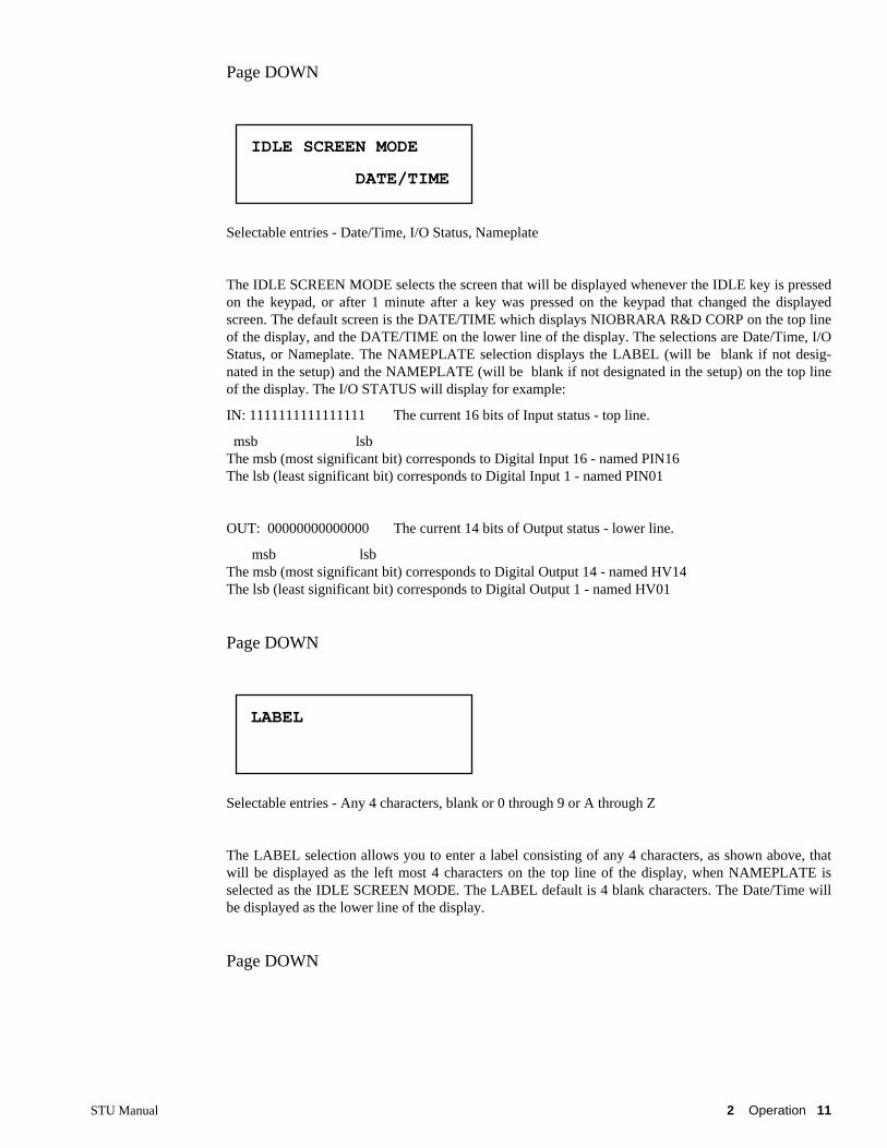
Selectable entries - Date/Time, I/O Status, Nameplate
The IDLE SCREEN MODE selects the screen that will be displayed whenever the IDLE key is pressedon the keypad, or after 1 minute after a key was pressed on the keypad that changed the displayedscreen. The default screen is the DATE/TIME which displays NIOBRARA R&D CORP on the top lineof the display, and the DATE/TIME on the lower line of the display. The selections are Date/Time, I/OStatus, or Nameplate. The NAMEPLATE selection displays the LABEL (will be blank if not desig-nated in the setup) and the NAMEPLATE (will be blank if not designated in the setup) on the top lineof the display. The I/O STATUS will display for example:
IN: 1111111111111111 The current 16 bits of Input status - top line.
msb lsbThe msb (most significant bit) corresponds to Digital Input 16 - named PIN16The lsb (least significant bit) corresponds to Digital Input 1 - named PIN01
OUT: 00000000000000 The current 14 bits of Output status - lower line.
msb lsbThe msb (most significant bit) corresponds to Digital Output 14 - named HV14The lsb (least significant bit) corresponds to Digital Output 1 - named HV01
Page DOWN
Selectable entries - Any 4 characters, blank or 0 through 9 or A through Z
The LABEL selection allows you to enter a label consisting of any 4 characters, as shown above, thatwill be displayed as the left most 4 characters on the top line of the display, when NAMEPLATE isselected as the IDLE SCREEN MODE. The LABEL default is 4 blank characters. The Date/Time willbe displayed as the lower line of the display.
Page DOWN
IDLE SCREEN MODE
DATE/TIME
LABEL

12 Operation 2 STU Manual
Selectable entries - Any 16 characters, blank or 0 through 9 or A through Z
The NAMEPLATE selection allows you to enter a nameplate consisting of any 16 characters, as shownabove, that will be displayed as the right most 16 characters on the top line of the display, whenNAMEPLATE is selected as the IDLE SCREEN MODE. The NAMEPLATE default is 16 blank char-acters. The Date/Time will be displayed as the lower line of the display.
Page DOWN
Selectable entries - 1 through 8192
The DIGITAL IN ADDRESS is the register address for the 16 digital inputs. The default is 6800.
NOTE: If this function is programmed at the same address as another function, the I/O register will respond to the specified address and the standard function will be inaccessible.
Page DOWN
Selectable entries - 1 through 8192
The DIGITAL OUT ADDRESS is the register address for the 14 digital outputs. The default is 6801.
NOTE: If this function is programmed at the same address as another function, theI/O register will respond to the specified address and the standard functionwill be inaccessible.
Page DOWN
NAMEPLATE
DIGITAL IN ADDRESS
REGISTER 6800
DIGITAL OUT ADDRESS
REGISTER 6801

STU Manual 2 Operation 13
The SET CLOCK selection allows you to set the PRESENT Date/Time. To set the Date/Time, use thearrow left or arrow right keys to position the cursor (an underline) under the desired character to bemodified and then press either the + key (to increase the value) or the - key (to reduce the value) tochange the character to the character desired. Move the cursor to the next character to be modified andrepeat, if necessary. You may press the idle key to return to the idle screen or the 1 minute time-outtimer will return the display to the IDLE SCREEN MODE display after the last key press. You mayalso press any key other than + or - when finished ( STATS, SETUP, PAGE UP or PAGE DOWN).
Page DOWN
Selectable entries - Any four digits 0 through 9999
The EDIT SETUP PASSWORD screen allows you to either NOT have or to select a 4 digit passwordthat will be required any time the SETUP key is pressed. Setting the password to 0 (zero) disables thepassword requirement. This feature would prevent unauthorized modifications of the setup, or un-authorized changes to values of registers in the STU unit. The default is 0 (zero) with the passwordrequirement disabled.
Page DOWN
Selectable entries - Hexadecimal, Binary, Signed, Unsigned
The REGISTER EDIT MODE selects the format of the characters used to enter values into a register.The selection of Hexadecimal requires the values to be input as a hexadecimal number using the char-acters 0 through 9 and ’a’ through ’f’. The selection of Binary requires the values to be input as a 16 bitbinary number using only the characters 0 or 1. The selection of Signed requires the values to be inputas a signed (+ = positive, - = negative) number in the range of -32768 to +32768.
NOTE: You MUST pay attention to the SIGN and enter a + for a positive number or enter a - for a negative number. The selection of Unsigned requires the
SET CLOCK
25Nov1997 10:11:10
EDIT SETUP PASSWORD
0
REGISTER EDIT MODE
HEXADECIMAL

14 Operation 2 STU Manual
values to be input as a unsigned (positive only) number in the range of (positive) 0 to 32768.
Page DOWN
Selectable entries - Any register 1 through 8192
The PRESS ZERO TO EDIT REGISTER ---- allows you to view, or edit (change), the value of anyregister that can be written to.
NOTE: Be sure you have entered the register number of the register you want to edit (change). Also, be sure of the mode selected in the REGISTER EDITMODE to know how the value is to be entered.
To view or edit a register, use the arrow left or arrow right keys to position the cursor (an underline)under the desired digit of the register number, to be modified and then press either the + key (to in-crease the value) or the - key (to reduce the value) to change the digit to the digit desired, then pressthen ZERO key to view or edit (change) the contents. To edit (change) the contents of that register, usethe arrow left or arrow right keys to position the cursor (an underline) under the desired character to bemodified and then press either the + key (to increase the value) or the - key (to reduce the value) tochange the character to the character desired. Move the cursor to the next character to be modified andrepeat, if necessary. If you are using the SIGNED REGISTER EDIT MODE, either the + (plus) key orthe - (minus) key will toggle the displayed SIGN + or - displayed to the other sign. BE SURE THESIGN DISPLAYED IS CORRECT . Default is last accessed register.
All unsupported registers respond with 8000 in Hexadecimal, with -32768 in Signed, with 32768 in Unsigned, with 1000000000000000 in Binary.
STATS key displays:
Digital Input Status bits - 1111111111111111 msb lsbThe msb (most significant bit) corresponds to Digital Input 16 - named PIN16The lsb (least significant bit) corresponds to Digital Input 1 - named PIN01
The STATS key displays the DIGITAL IN STATE of the 16 Digital Input bits.
Press ZERO to edit
register 6995
DIGITAL IN STATE
1111111111111111
STU Manual 2 Operation 15
Page DOWN
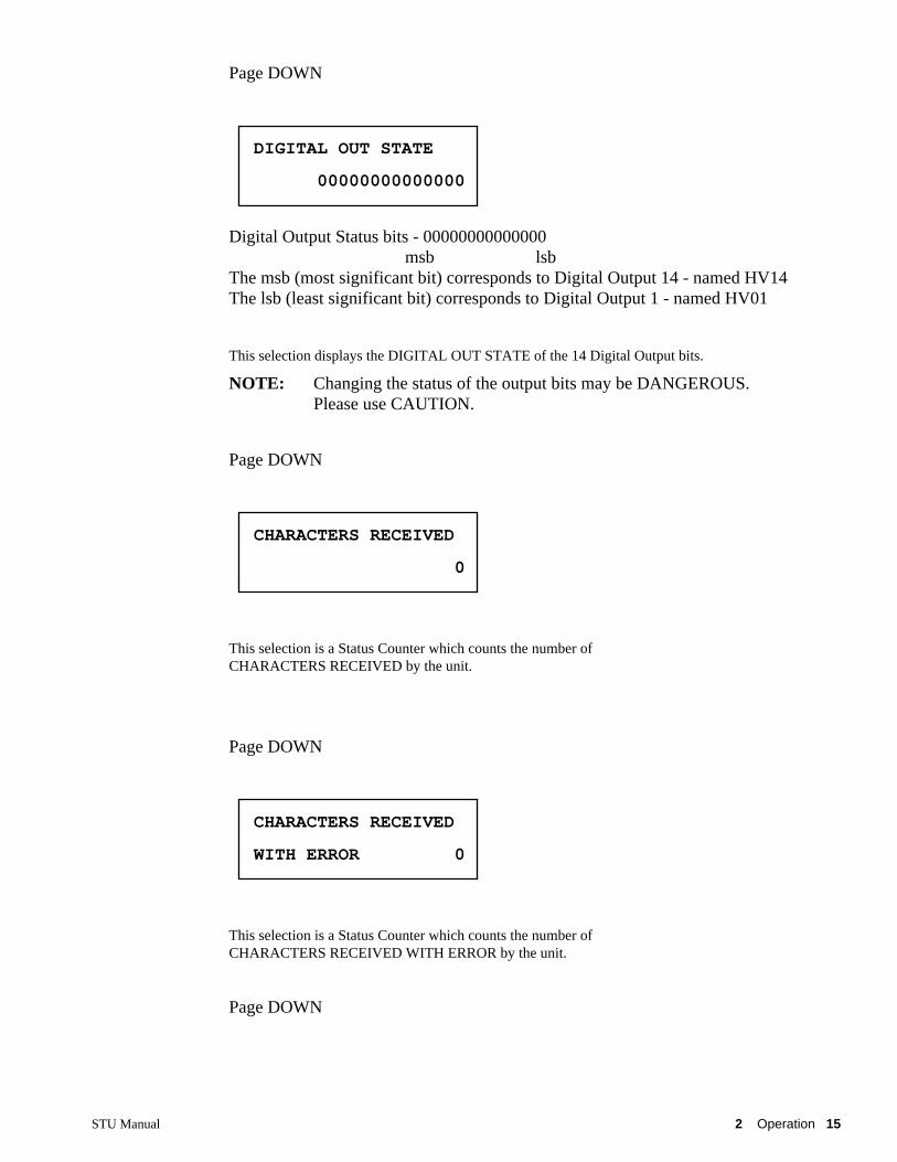
Digital Output Status bits - 00000000000000 msb lsbThe msb (most significant bit) corresponds to Digital Output 14 - named HV14The lsb (least significant bit) corresponds to Digital Output 1 - named HV01
This selection displays the DIGITAL OUT STATE of the 14 Digital Output bits.
NOTE: Changing the status of the output bits may be DANGEROUS.Please use CAUTION.
Page DOWN
This selection is a Status Counter which counts the number of CHARACTERS RECEIVED by the unit.
Page DOWN
This selection is a Status Counter which counts the number of CHARACTERS RECEIVED WITH ERROR by the unit.
Page DOWN
DIGITAL OUT STATE
00000000000000
CHARACTERS RECEIVED
0
CHARACTERS RECEIVED
WITH ERROR 0

16 Operation 2 STU Manual
This selection is a Status Counter which counts the number of CHARACTERS SENT by the unit.
Page DOWN
This selection is a Status Counter which counts the number of GOOD PACKET RECEIVED by the unit.
Page DOWN
This selection is a Status Counter which counts the number of BAD PACKET RECEIVED by the unit.
Page DOWN
This selection is a Status Counter which counts the number of PACKETS SENT by the unit.
CHARACTERS SENT
0
GOOD PACKET RECEIVED
0
BAD PACKET RECEIVED
0
PACKETS SENT
0

STU Manual 2 Operation 17
Page DOWN
This selection is a Status Counter which counts the number of PRIORITY READ commands sent to the unit.
Page DOWN
This selection is a Status Counter which counts the number of PRIORITY WRITE commands sent to the unit.
Page DOWN
This selection is a Status Counter which counts the number of NON-PRIORITY READ commands sent to the unit.
Page DOWN
This selection is a Status Counter which counts the number of NON-PRIORITY WRITE commands sent to the unit.
PRIORITY READ
0
PRIORITY WRITE
0
NON-PRIORITY READ
0
NON-PRIORITY WRITE
0

18 Operation 2 STU Manual
Page DOWN
This selection is a Status Counter which counts the number of commands containingan ILLEGAL OPCODE sent to the unit.
Page DOWN
This LAST ROUTE selection is a Status display which shows the last (1 of 2) route of communication sent to the unit. SEE the NOTE at end of next display description.
Page DOWN
This LAST ROUTE selection is a Status display which shows the last (2 of 2) route of communication sent to the unit.
NOTE: The LAST ROUTE (1 of 2 ) and (2 of 2) display the last route sent to theSTU unit, that the unit responded to. There are 8 bytes for storage of
the last route. Bytes 1 through 4 of the last route are displayed in the LAST ROUTE (1 of 2) and bytes 5 through 8 of the last route aredisplayed in the LAST ROUTE (2 of 2). The entire LAST ROUTE,,a total of 8 bytes, is viewed by combining LAST ROUTE (1 of 2),followed by LAST ROUTE (2 of 2).
Page DOWN
ILLEGAL OPCODE
0
LAST ROUTE (1 of 2)
0, 0, 0, 0,
LAST ROUTE (2 of 2)
, 0, 0, 0, 0

STU Manual 2 Operation 19
The LAST POWER UP selection is a Status display which shows the last Date/Time for power up ofthe unit. It would either show the first Date/Time it was powered up or it would show the lastDate/Time of a power failure when power was restored to the unit..
Page DOWN
This selection is a Status display which shows the Revision date of the firmware in an Eprom inside theSTU unit.
LAST POWER UP
25Nov1997 9:54:41
Nerd-I/O Rev 26Nov97
by Niobrara R&D Corp


STU Manual 3 Installation 21
3
Installation
Module Installation1 Mount the STU on any suitable mounting surface, in a position such that the LCD display screen is
above the keypad and at a good height for viewing the LCD screen, using 4 screws, one in eachcorner of the unit. Route the wiring in such a manner as to allow unobstructed LCD screen view-ing and easy access to the mounting screws and terminal strips for future additional wiring, and/orchangeout of the unit.
2 With power applied to the unit, the red LED (on Engage Networks Inc. units, the red LED is hid-den behind the terminal strip connector below the RS-485 4 wire terminals at the top right cornerof the unit as viewed while looking at the LCD screen) should be illuminated and remain lit. TheLCD screen should display the screen that is configured in the ’SETUP-IDLE SCREEN MODE’parameter (default is the NRD logo and Date/Time). This indicates that the STU has passed itsinternal self checks and is ready.
Cable installation
STU Power Supply
A 9 to 36 VDC power supply is required for the Z-World Little Star STU unit. Z-World can supply a24 VDC wall power supply. Typical draw at 24 VDC is 60 mA. The transformer Ground and DC wiresconnect to the GND and +DC terminals, respectively, on the top of the unit, at the left end, when look-ing at the LCD display.
RS-485 Connector
The STU connects to a RS-485 4-wire communication unit, such as a NRD PEN device, using a cablewith a male DB9 connector. The pinout of this connector and the suggested wire colors for the RS-485cable is shown in Table 3-1.

22 Installation 3 STU Manual
Table 3-1 STU RS-485 4-wire Connector
NOTE: The NET I/O RS-485 4 wire terminals are NOT in numerical order. They are from the upper right end of the terminal strip, when viewed while looking at the LCD screen, - in order - 21, 20, 23, 22 - please see label. (Your connection wire colors should be - in order - White, Green, Black, Red from outer edge toward center of top of unit).
STU ConfigurationThe STU keypad has different keypad definitions from the Engage Net-I/O. A keypad label insert issupplied with STU ROMs. The STU key definitions are as follows:
Idle Setup Page Up <--- + (none)
Stats Zero Page Down ---> - (none)
IDLE - Returns the keypad and display to idle after adjusting the setup or viewing the statistics screens.Pressing the IDLE key displays the screen that is selected in the setup under IDLE SCREEN MODE.The STU default display is DATE/TIME of the choices Date/Time, I/O Status, or Nameplate.
NOTE: The unit is always capable of communicating regardless of thekeypad/display state.
SETUP - Access configuration setup screens. Use PAGE DOWN and PAGE UP to scroll through indi-vidual screens.
STATS - Access statistic counter display screens. Use PAGE DOWN and PAGE UP toscroll through individual screens.
ZERO - When displaying any statistics counter, the Zero will clear all statistics counters. The Zero keyis also used to toggle between the register number and register data screens when editing a registerfrom the front panel.
PAGE UP - Display the previous setup or statistics screen.
PAGE DOWN - Display the next setup or statistics screen.
<--- - Move the cursor to the left in a setup screen.
---> - Move the cursor to the right in a setup screen.
+ - Increase the digit or option at the cursor.
- - Decrease the digit or option at the cursor.
(none) - STU firmware does not use these keys.
DB9MPin
Function SuggestedWire Color
STU RS-485 4 wireconnection
1 In - White In - (21)
2 In + Green In + (20)
3 Out - Black Out - (23)
4 Out + Red Out + (22)
5-6 DB9M pins jumpered in hood Any color
7-8 DB9M pins jumpered in hood Any color
9 Not connected None

STU Manual 4 Internal Registers 23
4
Internal Registers
REGISTERSThe register address of the Digital Inputs and Digital Outputs are programmable.
NOTE: If either of these functions is programmed at the same address as another function listed below, the I/O register will respond to the specified addressand the standard function will be inaccessible.
Date and Time is stored in two circuit-monitor compatible formats: expanded (6 regs) and compressed(3 regs).
Table 4-1 Expanded Date and Time Registers
Table 4-2 Compressed Date and Time Registers
Last Power UpRegistersR[760-765]
Present Date &Time Registers
R[[784-789]
Descriptionand Valid
Values
Valid Values
Register 760 Register 784 Seconds 0 - 59
Register 761 Register 785 Minutes 0 - 59
Register 762 Register 786 Hours 0 - 23
Register 763 Register 787 Day 1 - 31
Register 764 Register 788 Month 1 - 12
Register 765 Register 789 Year 1900 - 2099
Last Power UpRegisters
R[1830-1832]
Present Date &Time RegistersR[1842-1844]
MSB Descriptionand Valid Values
LSB Descriptionand Valid Values
Register 1830 Register 1842 Month (1-12) Day (1-31)
Register 1831 Register 1843 Year (0-199) Hour (0-23)
Register 1832 Register 1844 Minutes (0-59) Seconds (0-59)

24 Internal Registers 4 STU Manual
The year is zero based on the year 1900.(1989 is 89 and 2009 is 109)
Last Power Up: R[1830-1832] and R[760-765]Present Time: R[1842-1844] and R[784-789]
Either copy of the present time may be written to set the real-time clock.
The Label and Nameplate registers are supported. This string may optionally be displayed on the LCDdisplay when the display/keypad is idle.
Table 4-3 Label and Nameplate Registers
Table 4-4 Statistical Counter Registers
Table 4-5 IP Address Registers for NR&D PEN
Register Description Data Type
R[2040-2041] Label Packed ASCII
R[2042-2049] Nameplate Packed ASCII
Register Description
R[2081] Good packets received
R[2083] Bad packets received. CRC or checksum error
R[2086] Packets transmitted
R[2090] Illegal Sy/Max or Modbus opcode
R[2091] Sy/Max Priority Read
R[2092] Sy/Max Priority Write or Modbus opcode 6 write
R[2093] Sy/Max Non-Priority Read or Modbus opcode 3 or 4 read
R[2094] Sy/Max Non-Priority Write or Modbus opcode 16 write
R[2095] Character with parity or framing error
R[2096] Character transmitted
R[2097] Good character received
R[2108-2111] Last route received (one drop per byte)
Register Description
R[6995] Mode word for PEN
R[6996-6997] The IP address as defined from the front panel setup screens or written fromthe serial port.
R[6998-6999] Nonvolatile, read/write. Not used by STU or PEN.

STU Manual 4 Internal Registers 25
Table 4-6 Setup Registers
If Protocol Mode is set to 0 (Power Logic), the unit will automatically identify and respond toPLOGIC-SY/MAX and PNIM type packets.PLOGIC-SY/MAX packets use a BCC checksum. PNIM packets use a CRC.
Modbus mode supports opcodes 03, 04, 06, 16, 100, and 08 with the echo back.
Power Logic mode supports SY/MAX opcodes 0x00, 0x02, 0x04, 0x20, 0x1E, and 0x22.
Opcode 0x22 (network print) causes a message to be displayed on the LCD panel.
All unsupported registers respond with 0x8000.
Register Description
R[8035] Drop Number/Slave Address
R[8036] Baud Rate0=75, 1=150, 2=300, 3=600, 4=1200, 5=1800, 6=2400
7=3600, 8=4800, 9=7200, 10=9600, 11=14400, 12=19200
R[8037] Data Bits Read only constant 8
R[8039] Parity Bits 0=none, 1=odd, 2=even
R[8062] Options Bit mapped options. None used.
R[8040] Protocol Mode 0=PowerLogic, 1=Modbus RTU
R[8044] Input Register Defines register number for digital inputs
R[8045] Output Register - Defines register number for digital outputs
R[8174] Write 0x9090 to clear setup to factory default
R[8176] Port Number Read only constant 0x8001
R[8177- 8186]
Module ID Packed ASCII
R[8188] Sy/MAX ID Read only 0x9990


STU Manual 5 Examples 27
5
Examples
Example 1, A Simple ConfigurationThis example covers a very simple RS-485 4 wire system consisting of a NRD PEN, STU, an overtemperature sensor (open/closed), and an output controlling a relay.
Figure 5-1 Example 1
PS
PEN
SERIALCONNECTIONS
Green IN+White IN-Red OUT+Black OUT-
AUI
SERIAL TXSERIAL RX
BUSYERROR
ETHERNET
PS
Niobrara R&D Corp
25Nov1997 10:03:48
RELAY
TEMPSENSOR
RS-485 4-Wire Serial Cable

28 Examples 5 STU Manual
The STU modules may be placed anywhere in the chain of RS-485 4 wire units attached to a communi-cation unit (NRD PEN). More RS-485 4-Wire serial devices may be daisy chained from each unit toeach added unit. The last serial device MUST be terminated with a terminating device such as a SquareD model MCT-485 device.

STU Manual 6 Connector Pinouts 29
6
Connector Pinouts
STU RS-485 4-Wire Cable with male DB9 connector
Figure 6-1 RS-485 4-Wire Male Cable Connector Front Pinout
( looking at male pins of connector)
DB9MPin
Function Suggested Wire Color STU RS-485 4 wireconnection
1 In - White In - (21)
2 In + Green In+- (20)
3 Out - Black Out - (23)
4 Out + Red Out + (22)
5-6 DB9M pins jumpered inhood
Any color
7-8 DB9M pins jumpered inhood
Any color
9 Not connected None
123
45
67
89

30 Connector Pinouts 6 STU Manual
Figure 6-2 RS-485 4-Wire Male Cable Connector Back Pinout
( looking at wire solder cup side of pins of connector)
Figure 6-3 Top of NET I/O RS-485 4-Wire unit
543
21
98
76
WhiGrn
BlkRed

STU Manual 6 Connector Pinouts 31
Figure 6-4 Front of STU Remote Serial Terminal Unit
Figure 6-5 Bottom of STU Remote Serial Terminal Unit
Niobrara R&D Corp
25Nov1997 10:03:48


STU Manual 7 Trouble Shooting 33
7
Trouble Shooting
Troubleshooting the STUThe first step in troubleshooting the STU is to inspect the setup of the STU itself.
Booting
When the STU is first powered up, the screen selected in the IDLE SCREEN MODE should be dis-played. If the STU is not displaying this screen, it may be due to no power being supplied to the unit. Causes may include low or no 12V power from the wall transformer or an external connection hard-ware problem on the STU unit itself. Please check the voltage at the terminal strip and the tightness ofthe connections. If the connections are tight and the proper voltage is measured at the terminal strip, theunit may need to be returned to the factory for inspection and service. Call NR&D for a Return Mate-rial Authorization number (RMA) before sending the unit in.
Troubleshooting the RS-485 network
RS-485 device communications
RS-485 serial communications can be either 2-wire or 4-wire communications. RS-485 serial communi-cations may be multi-drop. The STU supports RS-485 4-Wire multi-drop communications.
• Incorrect RS-485 Cable Connection. Check that the STU’s RS-485 pigtail is connectedwith the GREEN wire to the IN+, the WHITE wire to the IN-, the RED wire to the OUT+, and theBLACK wire to the OUT-. Check all other connected devices to be sure that all of the IN+s areconnected to the other IN+s, IN-s to the other IN-s, OUT+ to OUT+, and OUT- to OUT-. Thereshould be a terminator on only the last slave device on the network. The Shield should begrounded at only one location of the RS-485 network. Initial troubleshooting may be easier if onlydevice #1 is connected; then adding additional units after communication is established with device#1.
• Incorrect addressing of slaves. All slave devices on the RS-485 network must be uniquelyaddressed. These addresses must be within the range of 1 through 8 inclusive. There MUST beone slave with the Address = 1. Make certain that all devices have their own address and that oneis set for 1. Initial troubleshooting may be easier if only device #1 is connected; then adding addi-tional units after communication is established with device #1.

34 Trouble Shooting 7 STU Manual
The statistical registers can be used to troubleshoot communications.
The STU unit contains statistcal registers, which are Registers R[2081], R[2083], R[2086], R[2090-2097], and R[2108-2111].
R[2095], Character with Parity or Framing Errorcan be monitored to see if the count is increasing, which could indicatethe Parity is set wrong, or the communication mode set wrong. Be surethat all communication parameters match for all devices on theRS-485 wire daisy-chain.
R[2083], Bad Packets Received. CRC or Checksum Errorcan be monitored to see if the count is increasing, which could indicatethe Checksum is set wrong. Be sure that all communication parameters match for all devices on the RS-485 wire daisy-chain.
R[[2081], Good Packets Receivedcan be monitored to see if the count is increasing, and closely matches thenumber of packets sent by the transmitting communication device that the STU unit is connected to.
R[2108-2111], Last Route Received (one drop per byte)can be monitored to see that the unit is responding to the messages for thecorrect drop number.
Additional troubleshooting help may be found in the Troubleshooting section for the communicationdevice that the STU unit is conected to.
STU Manual A NR&D Internet 35
Appendix ANR&D Internet
Niobrara is on the World Wide Web! Visit our home page at http://www.niobrara.com to see productinformation, cutsheets, application notes, and ftp current software releases.
Technical support questions may be E-mailed to
Marketing questions may be E-mailed to:


STU Manual B Upgrading Net-I/O to STU Firmware 37
Appendix B
Upgrading Net-I/O to STU Firmware
Because NRD I/O comes in a 512 Kbit (64 Kbyte) EPROM and Net-I/O firmware used varying sizesof Kbyte EPROMs, depending on the Revision, it is necessary to check/change some jumper settingson the Little Star PCB when replacing Net-I/O firmware.
On the jumper block, JP2 located above the EPROM, U6, move the jumper block to pins 3-5 and thejumper block to pins 2-4. The following diagram is not to scale. The jumpers should be positioned likeFigure B-1.
Figure B-1 Jumper Setting for Upgrading NET I/O to STU firmware.
NOTE: Default positions are shown for JP2. 3-5 and 2-4 determine Eprom size.Jumpers 7-9 and 8-10 are for pull up inputs. Jumpers 9-11 and10-12 are for pull down inputs. These should be set for theinput type you are using.
JP2
1
2
JP3
1
2
JP61
JP4
1
JP5
1
LED
BlackRed
Black
13
12
JP1
1
3
2
4

38 Upgrading Net-I/O to STU Firmware B STU Manual

STU Manual Index 39
Index
A
Addressing, Incorrect, 33
B
BAD PACKET RECEIVED, 16Baud Rate, 8Booting, 33
C
Cable Installation, 21CHARACTERS RECEIVED, 15CHARACTERS RECEIVED WITH ERROR, 15CHARACTERS SENT, 16Checksum, 25Compressed Date and Time Registers, 23Configuration, 22Connector, 22Connector Pinouts, 29Current and Votalge Requirements, 5
D
Date and Time, 23DIGITAL IN ADDRESS, 12DIGITAL IN STATE, 14DIGITAL OUT ADDRESS, 12DIGITAL OUT STATE, 9, 15Dimensions, 6
E
EDIT SETUP PASSWORD, 13Expanded Date and Time Registers, 23
G
GOOD PACKET RECEIVED, 16
H
http://www.niobrara.com, 35Humidity Rating, 5
I
IDLE, 22IDLE Key, 7IDLE SCREEN MODE, 11ILLEGAL OPCODE, 18Incorrect Addressing, 33Input / Output Specifications, 5Installation, 21INTERFACE MODE, 8INTERFACE PARITY, 9INTERFACE SPEED, 8Internet, 35Introduction, 5IP ADDRESS, 10IP Address Registers for NR&D PEN, 24
J
Jumper Settings, 37
K
KEYPAD KEYS, 7
L
LABEL, 11Label, 24Label and Nameplate Registers, 24LAST POWER UP, 19LAST ROUTE (1 of 2), 18LAST ROUTE (2 of 2), 18LCD Display, 7
M
Marketing Questions, 35

40 Index STU Manual
Modbus mode, 25Module Installation, 21Mounting Requirements, 5
N
NAMEPLATE, 12Nameplate, 24NETWORK PROTOCOL, 10Net-I/O, 37NON-PRIORITY READ, 17NON-PRIORITY WRITE, 17Note:, 7NOTE:, 12, 13, 14, 15, 18, 22, 23, 37
O
Operating Temperature, 5
P
PACKETS SENT, 16PAGE UP / DOWN, 22PARITY, 9PEN IP ADDRESS, 10PEN NETWORK PROTOCOL, 10PEN SERIAL PROTOCOL, 9PEN SY/MAX DROP, 10Pinouts, 29Power Logic mode, 25Power Supply, 21PRIORITY READ, 17PRIORITY WRITE, 17Protocol Mode, 25
R
REGISTERS, 23REGISTER EDIT MODE, 13RS-485 Connector, 21
S
SCREEN MODE, 11SERIAL PROTOCOL, 9SETUP, 22SETUP Key, 8SETUP PASSWORD, 13Setup Registers, 25SET CLOCK, 13Specifications, 5Statistical Counter Registers, 24STATS, 22STATS Key, 14SY/MAX DROP, 10
T
Technical Support, 35Termination, 28Time and Date, 23TRADEMARKS, 2Troubleshooting, 33
U
Unsupported Registers, 25Upgrading from Net-I/O, 37Upgrading to NRD I/O, 37
W
Web, 35World Wide Web, 35
Z
ZERO, 22