studies on new processing aids and other compounding...
TRANSCRIPT

CHAPTER V

Chapter V
USE OF RICE BRAN OIL AS PLASTICISER IN NBR-PVC BLENDS
The importance of plasticiser in the compounding of PVC could be
appreciated only when we consider the fact that the usage of PVC was limited till the
widespread use of plasticisers during 1930's, eventhough the discovery of PVC itself dates
back to more than a century. Compared to elastomers, PVC which is a polymer with
certain limitations like medium molecular weight, low crystallinity, poor heat stability
above its softening point, low resistance to UV radiation and low softening point (70-75°C)
found extensive application like other commodity plastics mainly due to the discovery of
plasticisers and heat stabilizers. PVC resins are generally classified into suspension and
emulsion grade depending on the techniques employed for their manufacture. Particles of
suspension PVC are roughly spherical with diameter in the range of 50-250 micrometers.
They have a porous internal structure with a significant volume of interstitial voids capable
of absorbing plasticisers. Most resins used in the melt processing of plasticised PVC are of
the suspension grade. More than 80% of PVC production accounts for this type of resin.
However the emulsion polymer comprises small «1 /lm diameter) spherical particles.
This type of resin can form plastisols when mixed with plasticisers at ambient temperature.
There is no absorption of plasticisers by the primary particles which retain their integrity
until the temperature is raised to cause fusion. Discovery of plasticisation of PVC by low
molecular weight alkyl esters by B.F. Goodrich was of prime importance. In fact the
plasticisation of PVC made it more akin to rubber than plastics. It was also found that
115

most of the additives used in rubber industry like oils, waxes, stearates and metal oxides
were also useful in PVC processing.
A brief discussion of role of plasticisers in PVC may be useful as the
present study evaluates the role of RBO as a plasticiser in NBR~PVC blend. The proper
choice of a plasticiser becomes an important part of PVC compounding. The efficiency of
a plasticiser, otherwords the ability ofa plasticiser in changing the properties of PVC to the
desired extent with the use of as little plasticiser as possible is of paramount importance
while selecting a plasticiser. In PVC industry this efficiency of a plasticiser is again a
measure of how fast plasticisation takes place for a given grade. In general this depends on
compatibility and molecular weight of the plasticiser. More compatible plasticisers are
absorbed faster at a lower temperature compared to less compatible plasticisers for a given
PVC sample. Now it has been well established that for the plasticiser molecules to be
effective they must consist of sticky bits (to bind them to the polymer) and floppy bits (to
separate polymer chains and allow movement. 1 In other words in order to be compatible
with a polymer, a plasticiser needs to contain structural components which give loose
reversible binding to the polymer; typically by dipole-dipole attraction. The remainder of
the attached molecule, together with unattached molecules creates additional free volume
in the structure which allows movement of the polymer chains and renders the material
flexible. A simple model indicating favoured
polymer/plasticiser dipole alignments in plasticised PVC is shown in Fig.5.1? Patel et al. 3
studied the effect of type and concentration of plasticiser on the behaviour of PVC,
116

o ~R
Fig. 5.1 Leuch's model of plasticisation
117
'Screen' type plasticiser
(e.g. adipates)
'Hinge' type plasticiser
(e _ 9 _ phthalates)

especially the fusion properties. More recently, access to molecular modelling computer
programme and solid state nuclear magnetic resonance spectroscopy has given indications
of the more complex interactions which are likely to occur in reality.4
Molecular mass, polarity and linearity of polymer molecules etc. are the
most important molecular parameters that are to be considered while predicting
performance of a particular plasticiser for use in PVC. Now it is almost clear that any
compound with a molecular mass below 300 is likely to be too volatile for use in PVC and
values above 800 causes low compatibility, and efficiency and hence difficult in
processing. As far as the polarity aspect of the ester plasticiser molecule is concerned
calculation of ArfP 0 ratio will give an indication of processability and compatibility. This
ratio is equal to the number of carbon atoms present in the molecule (excluding
aromatic carbon atoms) divided by the number of ester groupS.5 The aromatic carbon
atoms are excluded from this calculation mainly due to the polarisable nature of aromatic
groups which contributes to interaction. In this treatment, their effect is rated as neutral.
As far as the linearity of the plasticiser molecule is concerned, if the structure is
predominantly cyclic or branched, then the material will show poor low temperature
performance. At an early stage, in the development of polymer technology the relationship
between viscosity and plasticising performance was recognised by Leilich and this became
known as Leilich's rate.6 According to this rule the low viscosity indicates high softening
efficiency, but at the cost of increasing tendency for rapid migration.
118

Lubricants also play an important role in PVC compounding. They are
mainly used to reduce friction arising out of lack of ease of slippage of polymeric chains
with respect to each other .. This friction can give rise to heat and hence the temperature of
the melt increases, and hence can sometimes be detrimental to the stability, viscosity,
colour etc. of the resin. The control of temperature to required level is an important
requirement in PVC processing. Generally two different types of lubricants namely the
internal and external types are used. The internal lubricants reduce the friction arising out
of polymer chains whereas the external ones help to reduce friction between metal surface
and the polymer chains in contact with it. However, there are certain class of lubricants
which can perform dual roles and hence are called internal-external lubricants. Internal
lubricants are quite compatible with PVC with the result that addition of these reduce
internal friction, melt viscosity etc. giving better overall flow at lower power consumption.
In this sense they are similar to plasticisers and often difficult to distinguish from them. It
is a well known fact that plasticisation tends to decrease hardness and T g, something which
an internal lubricant also can do, though it has only limited compatibility with PVC.
External lubricants have poor compatibility with PVC and hence tend to migrate towards
surfaces thereby increasing lubricity between the melt and metal surface. Thus they have
less effects on melt viscosity as compared to internal lubricants.
An ideal plasticiser is one which would show zero loss from the plasticised
product and would remain chemically unchanged despite prolonged exposure to heat, light,
aggressive chemicals, microorganisms and in contact with a wide variety of extracting
media. Both thermodynamic and kinetic factors involve during a plasticiser loss from
PVC. Thermodynamic factor covers the strength of interaction of the plasticiser with PVC
119

relative to its compatibility with the medium into which it is migrating. In the case of
volatile loss, vapour pressure is the measure of its compatibility with air. Kinetics deals
with the rate at which the plasticiser diffuses to the surface of the PVC and the rate at
which it migrates away from the surface into the adjacent medium. Again it is found that
the loss will be increased by any factor which degrades plasticiser molecules into smaller
fragments. These fragments will have lower PVC compatibility higher mobility and
perhaps greater compatibility with extractants than with the plasticiser itself. There are
many hostile factors which can remove the plasticiser from the polymer of which the
compatibility limit factor of a plasticiser in the polymer is also to be taken into account.
This factor may be defined as the level of incorporation of a plasticiser in PVC above
which it will exude or sweat from the surface of a fully processed compound. For general
purpose phthalates, phosphates etc. compatibility limits are far in excess of the levels
which would need to be used in practice. However for others like chlorinated paraffins and
some adipates compatibility limit places a real constraint to their use. Except fillers,
plasticisers constitute the largest class of plastic additives both in terms of value and
volume. Out of the total consumption of plasticisers world over approximately 90% is
phthalates esters. DOP (dioctyl phthalate), DINP (di-isonoyl phthalate) and DIDP (di
isodecyl phthalate) constitute the three major general purpose PVC plasticisers. DOP is
the largest single product used as a plasticiser throughout the world. In our study also the
efficiency ofRBO as plasticiser in NBRlPVC blend is compared to that of DOP. For ester
type plasticisers it is the ester groups which provide compatibility with PVC whilst the size
and shape of the remainder of the molecule dictates plasticising efficiency and
permanence. It is reported that penneation of oxygen in PVC is increased with increasing
120

nop content. 7 The glass transition temperature of PVC decreased and fractional free
volume increased with increasing nop content.
Miscibility of polymer blends was first observed with NBR':PVC system.
In contrast to incompatible blends, blends of NBR-PVC show a single broad glass
transition temperature (T g) over a temperature range between T g'S of the unblended
polymer. 8,9 However, studies of Matsuo et al10 and Rovatti et al ll have shown that
NBR-PVC blends are not truly compatible in molecular level and confIrmed the existence
of distinct phases. It was also noted that blending of nitrile rubber with PVC significantly
reduced, and in some cases eliminated, the loss of plasticiser due to volatilisation,
migration or extraction. 12 This blend also exhibited inherent oil and fuel resistance and b
were suited for wide range of applications. The main worth ofNBR PVC compounds is as '"
a nonextractable plasticiser. This is mainly due to the unique compatibility of PVC and
NBR polymers. The presence of NBR in the blend also gives the final product a rubber
look and feel. 13 It is also found that PVC forms a compatible blend with NBR in all
proportions provided NBR has an acrylonitrile content of 25 to 40%. Lower or higher
acrylonitrile content makes it incompatible with PVC. 14,15 Though NBR is not as efficient
a plasticiser as nop is, the former is used in the compounding of PVC due to its own
inherent strength and ability to confer better mechanical properties to the blend. Because
of the better mechanical properties of the blends they are widely being used in applications
like wire and cable jacketing, gaskets, foot-ball covers, shoe uppers, tubing etc. 16 NBR
also helps to retain any additional plasticiser like nop or chlorinated paraffm added to
PVC compounds. However NBR is not a good plasticiser as far as electrical resistance is ...
121

concerned and hence the blend fmds application only for making cable sheathing
compounds and not for insulation compounds. In the NBR-PVC blend PVC has dual role,
as a reinforcing filler and makes NBR resistant to ozone. In general, PVC is added to NBR
when superior ozone resistance and ageing resistance is required. Poor processability and
poor impact strength are the two major shortcomings of PVC. These shortcomings are
tackled by mixing with plasticiser or by increasing processing temperature or by blending
with NBR. This blending ofNBR with PVC improves impact strength of the rigid PVC
compositions and also increases the ozone resistance ofvulcanisates. 17,18
DOP being the largest tonnage plasticiser used in compounding of PVC,
extensive toxicological studies were undertaken by different scientific organisations in UK
and USA. 19 Results of studies conducted in USA in early 1980's indicated that substances
like DOP and DOA (dioctyl adipate) are harmful to human beings and are carcinogenic.20
But later studies absolved these substances from its carcinogenic potentia1.21 Apart from
the toxic nature, these chemical substances, can also contribute to the environmental
pollution as they can migrate from PVC compounds. Under this backdrop it will be
worthwhile if some of the chemical plasticisers like DOP traditionally being used in PVC
or its blends could be replaced by an ecofriendly and nontoxic substance like RBO.
In the present study a natural product viz., rice bran oil is used in place of
chemical plasticiser like DOP conventionally used for the preparation of NBR-PVC
blends. The effect of replacement of DOP by RBO in the blends was investigated by
compairing the processability, cure characteristics, physical and mechanical properties of
122

respective vulcanisates from the blends. In order to ascertain the behaviour of the oil in the
blend in presence of fillers, blends were prepared in different blend ratios with carbon
black/silica using RBO and their properties were compared to those prepared with DOP.
EXPERIMENTAL
NBR and PVC having specifications given in chapter II were used in the present
investigation. Zinc oxide, magnesium oxide, stearic acid, mercaptobenzothiazyl disulphide
(MBTS), tetramethyl thiuram disulphide (TMTD), sulphur, carbon black (HAF 330),
silica, dioctyl phthalate used are all of commercial grade. Stabiliser system consisting of
ZnO, MgO and stearic acid was used for PVC. The resin was Hrst thoroughly mixed with
stabilizers and then plasticiser DOPIRBO was added with thorough mixing so as to get the
ingredients uniformly mixed. Blends ofNBR and PVC were then prepared in a Brabender
plasticorder, model PL-3S. The mixing head was heated to 150°C and the rotor speed was
adjusted to 50 rpm. Mill masticated NBR was first added to mixing chamber and allowed
to heat up and homogenise for one minute. PVC compound was then added over a period
of 5 minutes and mixing was continued for 2 more minutes till a constant torque is
recorded in the torque rheometer. The final compounding of the blends prepared in
different blend ratios using fillers and DOPIRBO was done in a laboratory model two-roll
mixing mill at a temperature of 80·C as per the formulation given in Tables 5.2, 5.3 and
5.4. The amount of curatives used in the blend was selected on the basis of weight
percentage ofNBR in the blend. When black was used as the filler 4 pbr of DOPIRBO
was used as processing aid and for silica 6 pbr processing aid was required. These
quantities of oils were selected based on the results obtained on our earlier studies ofNBR
123

processability using DOPIRBO as mentioned in Chapter Ill. The final compound so
prepared was kept for maturation at 27°C for a period of 24 hrs.
When silica is used as a filler in rubber compounds acidic silano Is or
hydroxyl groups on the surface of the filler can interact with basic accelerators. This
usually results in unacceptable long cure times and slow cure rates. In order to normalise
the cure rate, diethylene glycol (DEG) is usually included in the compound preparation. In
our study also 1.5 phr diethylene glycol was used for the preparation of silica filled blends.
The cure characteristics of the compounds were determined at 160°C on a
Geottfert elastograph model 67.85. The cure data reported are the following: Optimum
cure time is the time taken for attaining 90% of the maximum torque. Elastographic
scorch is calculated as the time for 10% of vulcanisation. Cure rate index was determined
from the cure curves of the respective mixes as 100It90-t1O, where t90 and tlO are times
corresponding to the optimum cure and ten percent vulcanisation respectively. The
maximum - minimum torque (MHF - ML) of each mix was also calculated. The
compounds were vulcanised upto their optimum cure time in an electrically heated
laboratory type hydraulic press at 160°C and at a pressure of 11.764 MPa. The tensile
properties of the vulcanisate were determined on a Zwick universal testing machine using
a crosshead speed of 500 mmlmin. as per ASTM designation D 412-87 (method A).
Dumbell specimens for the test were punched out of the moulded sheets along the mill
grain direction. Heat ageing was carried out at 100°C for 96h in an air oven. Tear
resistance is tested as per ASTM designation D 624-86 using angular test pieces.
124

Table 5.1 Formulation of PVC Compound
Ingredients Phr Poly (vinyl chloride) 100
ZnO 4
MgO 4
Stearic acid 2
DOPIRBO 20
Table 5.2 Formulation ofNBR in the unfilled blend
Ingredients Phr NBR 100
Sulphur 1.5
ZnO 3.0
Styrenated phenol 2.0
Stearic acid 1.0
MBTS 1.5
TMTD 0.5
125
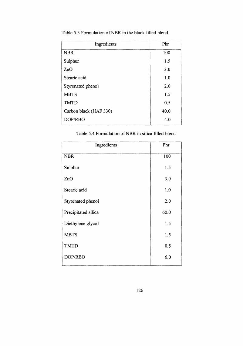
Table 5.3 Fonnulation ofNBR in the black filled blend
Ingredients Phr
NBR 100
Sulphur 1.5
ZnO 3.0
Stearic acid 1.0
Styrenated phenol 2.0
MBTS 1.5
TMTD 0.5
Carbon black (HAP 330) 40.0
DOPIRBO 4.0
Table 5.4 Fonnulation ofNBR in silica filled blend
Ingredients Phr
NBR 100
Sulphur 1.5
ZnO 3.0
Stearic acid l.0
Styrenated phenol 2.0
Precipitated silica 60.0
Diethylene glycol 1.5
MBTS 1.5
TMTD 0.5
DOPIRBO 6.0
126

Compression set was tested as per ASTM D 395-86 (method B). Abrasion resistance was
evaluated using DIN abrader (DIN 53516). The swelling index of the different samples
was detennined by immersing 0.2g of the sample in chloroform for 24hr. All these
experiments are described in detail in chapter H.
The processability study of NBR-PVC blend using DOPIRBO was carried
out in a Brabender plasticorder. For the present study the temperature of the test chamber
was kept at 150°C, and the speed of the roller mixing heads in the plasticorder was kept
initially at 50 rpm. The weight ofNBR, PVC and other ingredients were so selected as to
keep the total weight of the blend 40 gm for each blend ratio. First NBR was passed six
times in a two-roll mill at a nip gap of 0.8 mm to get a thin sheet. This was cut into small
strips before feeding into the plasticorder. The total mixing time was kept at 8 minutes
with the following break-up. NBR was allowed to heat up and homogenise for one minute,
then PVC resin premixed with ZnO, MgO, stearic acid, and DOPIRBO was added over a
period of 5 minutes, and the mixing was allowed to continue for two more minutes. The
fmal torque reading in the torque rheometer was recorded. The experiment was repeated
using different levels of DOPIRBO (15/20/25 phr) at different rpm (50, 70 and 90) in two
different blend ratios (50/50 and 70/30). Viscosity (torque/rpm) of the blend in each blend
ratios is plotted against rpm for different levels of oil used. The corresponding flow curves
are shown in Figs.5.2 and 5.3.
127

RESULTS AND DISCUSSION
Processability
The optimum quantity of DOPfRBO required for the blend preparation was
determined by using different levels of DOP/RBO during the preparation of the blend in
the Brabender plasticorder. For SO/50 and 70/30 NBR-PVC blend 15,20 and 25 phr levels
of DOPIRBO were tried. From the flow curves shown in Figs.5.2 and 5.3 it is clear that
the maximum torque obtained in SO/50 and 70/30 NBR-PVC blends during mixing at
150°C and at 50 rpm is well within 30 Nm range. It may also be noted that a near absence
of any white patches (due to unfused PVC particles) on the surface of the thin sheet made
out ofthe DOPfRBO based blend by passing through a two roll mill at a nip gap of 0.8 nm
can be considered as indication of the uniformity ofthe blend. Here 20 phr DOPfRBO (for
100 phr PVC) is taken as the optimum level of the plasticiser for the preparation of the
blend as this amount was found to be enough for the preparation of a uniformly mixed
blend.
The same loading of rice bran oil produced less torque values compared to
DOP and this is seen reflected in the lower viscosity (torque/rpm) of the blends prepared
with RBO. This lower viscosity of the blends prepared with RBO may be attributed to the
ability of RBO to function as an extemallubricant also in the blend. From the flow curves
for the blends under review, it is clear that both the systems are pseudoplastic as seen from
the decrease in viscosity with increase in rpm. When the level ofRBO is increased above
25 phr the preparation of the blend was found to be difficult as the torque developed was
too small to get a uniformily mixed blend within the stipulated period. From the flow
128

1-E ~
<I) :::l c-..... 0
f-<
100
80
60
40
20
60
40
20
015 PhrDOP
.20PhrDOP
~ 25 PhrDOP
o 15 PhrRBO
.20PhrRBO
~ 25 PhrRBO
rpm-7
100
Figure 5.2 Flow curves of 50150 NBR-PVC prepared at 150°C with UUP/ .f{HU
129

15 Phr OOP
20 PhrDOP
25 PhrDOP
60
40
1-E ~ IlJ ::::I 0" ... 0
20 r
15PhrRBO
20 PhrRBO
25 PhrRBO
60
40
20
40 60 80 100
Figure 5.3 Flow curves of70/30 NBR-PVC prepared at 150°C with DOP/ RBO
130

curves it is clear that in both 50/50 and 70/30 NBR-PVC blends, 20 phr of DOPIRBO, on
weight basis is sufficient for making a proper blend at the blending temperature of 150°C.
Based on the processability studies the experimental blends are prepared
using 20 phr RBO and their cure characteristics, physical and mechanical properties are
compared with the corresponding blends prepared with DOP. These results are reported in
the subsequent section. From the processability study it is evident that DOP could be
replaced with RBO for the preparation of the blend; the main advantage ofRBO over DOP
being that RBO offers lesser Brabender torque compared to DOP. This aspect will have
technological and economic advantage during the preparation of the blend.
Cure characteristics
The cure characteristics of the blends prepared with RBO in different blend
ratios with and without filler and the corresponding control compounds prepared with DOP
were evaluated using Goettfert elastograph at 160°C. The cure curves of the blends
prepared with DOP are given in Figs.5A, 5.5 and 5.6 and those with RBO are given in
Figs.5.7, 5.8 and 5.9. From the figures it is evident that the maximum torque developed
for all the blends prepared with DOP is higher compared to the ones prepared with RBO.
This is in accordance with the processing properties discussed in the earlier section. The
reason for this observation may be attributed to the better compatibility or lower
plasticizing nature of DOP over RBO. This observation is equally true for the blends
prepared with different fillers also. From the figures it is also evident that the blends under
review do not show any reversion characteristics irrespective of the nature of plasticisers
131

and fillers used. The cure characteristics of the blends with and without fillers prepared
with DOP are given in Table 5.5, 5.7 and 5.9 and of the corresponding blends prepared
with RBO are given in Tables 5.6, 5.8 and 5.10. From the cure time values of the different
blends prepared with DOPIRBO it is clear that the incorporation of RBO in the blend gives
a favourable effect as seen by increased cure rate in these mixes. This is especially so for
the black filled blends prepared with RBO. This trend is also shown by silica filled blends
prepared with RBO. This cure accelerating nature of the RBO may be due to the presence
of various kinds of free fatty acids present in the oil. The lower cure time and scorch time
values of the silica based blends prepared with RBO has got special significance, as silica
has traditionally been known for its cure retarding properties.22 It is a known fact that
accelerator systems are deactivated by silica. However the scorch time values (a measure
of processing safety) is higher for blends prepared with DOP compared to RBO and is true
for both filled and unfilled systems. The fact that incorporation of RBO in these blends in
place of DOP, significantly reduce cure time values can have defmite technological
advantages.
Crosslink density
The swelling index of the blend prepared with DOP/RBO were determined using
chloroform as the solvent. These swelling index values are a measure of crosslink density
as it is inversely proportional to the crosslink density. From Fig.5.18 it is clear that the
blends prepared with DOP show lower swelling value and hence higher crosslink density
as compared to the ones prepared with RBO. This trend is shown by filled blends prepared
with DOP also. The greater compatibility ofDOP over RBO towards the blend may be
132

Table 5.5 Cure characteristics of unfilled NBR-PVC blends with DOP
Blend ratio
50/50 60/40 70/30 80/20 90110
Maximum torque MHF(Nm) 0.121 0.198 0.208 0.224 0.236
Minimum torque ML (Nm) 0.013 0.018 0.016 0.014 0.014
(MHF - ML) torque (Nm) 0.108 0.180 0.192 0.210 0.222
Optimum cure time t90 (min) 7.6 7.4 5.8 5.2 3.9
Elastographlc scorch time t10 (min) 2.0 1.8 1.9 1.8 1.8
Cure rate index 18 18 26 30 48
Table 5.6 Cure characteristics of unfilled NBR-PVC blends with RBO
Blend ratio
50150 60/40 70/30 80/20 90110 ... Maximum torque MHF(Nm) 0.117 0.145 0.140 0.138 0.150
Minimum torque ML(Nm) 0.020 0.014 0.016 0.014 0.012
(MHF - ML) torque(Nm) 0.097 0.131 0.124 0.124 0.138
Optimum cure time t90( min) 6.9 5.5 5.2 4.7 2.6
Elastographic scorch time t10 (miu) 1.6 1.6 1.7 1.7 1.8
Cure rate index 18.8 25.6 28.6 33.3 125
133

Table 5.7 Cure characteristics of black filled NB~PVC blends with DOP
Blend ratio
50/50 60/40 70/30 80120 90110
Maximum torque MHF(Nm) 0.139 0.207 0.218 0.280 0.301
Minimum torque ML (Nm) 0.069 0.060 0.060 0.060 0.050
(MHF - ML) torque (Nm) 0.070 0.147 0.158 0.220 0.251
Optimum cure time t90 (min) 12.5 6.2 5.5 4.9 2.7
Elastographic scorch time t10 (min) 1.9 1.7 1.7 1.7 1.5
Cure rate index 9.43 22.0 26.0 31.0 83.0
Table 5.8 Cure characteristics of black filled NBR-PVC blends with RBO
Blend ratio
50/50 60/40 70/30 80120 90/10
Maximum torque MHF(Nm) 0.134 0.174 0.189 0.279 0.270
Minimum torque ML(Nm) 0.065 0.070 0.070 0.080 0.080
(MHF - ML) torque (Nm) 0.069 0.104 0.119 0.199 0.190
Optimum cure time t90(min) 3.1 3.1 2.9 2.8 1.5
Elastographic scorch time tlO (min) 1.6 1.7 1.7 1.7 1.1
Cure rate index 66.6 71.4 83.3 90.9 250
134

Table 5.9 Cure characteristics of silica filled NBR...pVC blends with DOP
Blend ratio
50/50 60/40 70/30 80120 90/10
Maximum torque MHF(Nm) 0.267 0.279 0.434 1.010 1.080
Minimum torque ML(Nm) 0.174 0.185 0.200 0.200 0.220
(MHF- ML) torque (Nm) 0.093 0.094 0.234 0.810 0.860
Optimum cure time t90 (min) 12.2 6.6 5.4 3.6 2.8
Elastographic scorch time tlO (min) 2.3 1.9 1.3 1.1 1.0
Cure rate index 10.1 21.2 24.4 40.0 55.6
Table 5.10 Cure characteristics of silica filled NBR-PVC blends with RBO
Blend ratio
50150 60/40 70/30 80120 90/10
Maximum torque MHJ{Nm) 0.195 0.270 0.420 0.730 1.070
Minimum torque ML(Nm) 0.113 0.167 0.200 0.200 0.210
(MHF - ML) torque(Nm) 0.082 0.103 0.220 0.530 0.860
Optimum cure time t90(min) 5.8 4.6 2.5 1.9 1.9
Elastographic scorch time 110 (min) 1.6 1.6 1.2 1.0 1.0
Cure rate index 23.8 33.3 76.9 111.1 111.1
135

cited as the reason for this observation. This observation is further supported by the fact
that MHr-ML (maximum torque - minimum torque) of the different blends with and
without fillers using DOP (Refer Tables 5.5, 5.6, 5.7, 5.8, 5.9 and 5.10) are higher than
those of the corresponding ones prepared with RBO. It is also reported that MHp-ML is a
direct function of crosslink density.23 From these observations it may be concluded that
better crosslinking in the blend is achieved when DOP is used in the blend compared to
RBO.
Tensile properties
The variation in tensile properties before and after ageing of the blend
vuIcanisates with and without fillers are represented in Figs.5.10 and 5.11. From the
figures it is clear that in the case of unfilled blend the tensile strength values are higher for
the ones prepared with DOP. This is evident from the higher crosslink density of these
blends. But as the weight percentage of PVC in the blend decreases tensile values also get
decreased. For the black filled blends except for 50/50 blend both DOP and RBO based
blends showed more or less same tensile values. For silica filled blends the tensile values
are more or less same for the 50/50 blend. However as the weight percentage of rubber in
the blend increases, the blends prepared with DOP showed better tensile values.
The elongation at break values of the different blend vuIcanisates are given
in Fig.5.12. From the figure it is clear that the elongation at break values are slightly
higher for the unfilled blends prepared with DOP. This is equally true for silica filled
blends also. The modulus at 200% (Fig.5.13) is also slightly higher for the unfilled and
136

silica filled blends prepared with DOP, which again is indicated by the higher crosslink
density of the vuIcanisates from these blends. After ageing the different vulcanisates at
100·C for 96hr, it is found that the percentage retention of tensile values are more for
unfilled and black filled blends prepared with DOP compared to RBO. However a reverse
trend is noted for the silica filled blends. (Fig. 5.14).
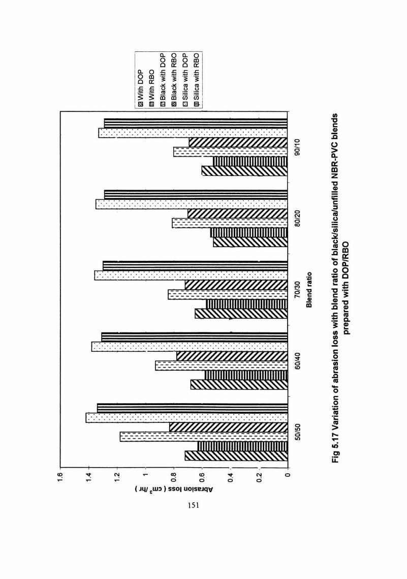
Tear strength, compression set and abrasion resistance are the other physical
properties studied for the different systems under review. These values are given in
Figs.5.15, 5.16 and 5.17. It is clear from the figures that the tear values are decreasing as
the weight percentage of PVC in the blend decreases irrespective of the nature of the
plasticiser used. This is a clear indication of the better tear strength afforded by PVC to the
blend both in the filled and unfilled systems. It may also be noted that with few exceptions
the tear strength values of the different vulcanisates prepared with DOP are slightly higher
compared to the ones prepared with RBO. It may also be attributed to the greater
compatibility of DOP over RBO towards the blend. A notable feature of the blends
prepared with RBO is the better abrasion resistance values of these vulcanisates compared
to the corresponding ones prepared with control (Fig.5.17). This may be ascribed to the
lower stiflhess of the blend vulcanisate prepared with RBO. The compression set values
are more or less same for all the blends prepared with DOP and RBO (Fig.5.16). However
the compression set values are decreasing as the weight percentage of PVC in the blend
decreases. This may be due to the greater rubber chain flexibility brought about by the
decreasing amount of PVC in the blend.
137

Conclusions
1. From the processability studies it is obvious that the incorporation of RBO in the
blend has beneficial effect as the torque generated is found to be significantly less
compared to the control blends based on DOP.
2. The cure characteristics of the blends prepared with RBO suggest that RBO has
cure accelerating property (higher cure rate values) compared to the ones prepared
with DOP. The lower cure time values has a direct bearing on the processing
operations with defmite technological advantage.
3. A comparison of the mechanical properties of the blends prepared with DOP and
RBO indicate that the replacement of DOP by RBO does not affect the physical
and mechanical properties of the blends significantly eventhough DOP is found to
be slightly superior in some of the physical properties estimated. The high abrasion
resistance of the blends prepared with RBO may be considered as a beneficial
feature.
4. It may be concluded that replacement of DOP with RBO in the blend is
advantageous as RBO is available comparatively cheap in India. Apart from these,
RBO which is a nontoxic and ecofriendly natural product, could be recommended
as a plasticiser substitute for DOP in NBR-PVC blends.
138

REFERENCES
1. S.K. Sears and J.K.Darby, The Technology of Plasticisers, Chapters 2 and 3, John
WHey and Sons Inc., (1982).
2. D. Leuchs, Kunststoffe, 46,547 (1956).
3. S.V.Patel and M.Gilbert, Plast. Rubber Process: Appl. 6(4), 321-30 (1986).
4. C.Howick, PVC 93, Institute of Materials Conference, Paper 38, (1993).
5. G.J.Van veer Sen and AJ.Meakenbery, Kunststoffe, 56, 23 (1966).
6. K. Von Leilich, Kolloid-Z, 99,107-113 (1942).
7. Yun, Wehhui, Jiang, Bengzhency, Xu Jipiny, Yingyong Huaxue, 4(1), 62-66Ch (1987).
8. L.Nielson, J. Am. Chem. Soc. 75, 1435 (1953).
9. G.AZakrzewski, Polymer 14, 348 (1973).
10. M. Mat suo , C.Nozaki, Polymer Engr. Sci. 9,197 (1969).
11. W.Rovatti and E.G.Bobalek, J. Appl. Polym. Sci. 7, 2269 (1963).
12. L.A. Cobb, Stookdale,K. Michael, Plast. Compound, 11(5) 58-59 (1988).
13. K.A Pedley, Polymer Age, 1,97 (1970).
14. N.Nakajima and J.L.Liu, Rubb. Chem. Technol. 65,453 (1992).
15. K. Fukumori, N. Sato and T. Kurauchi, Rubb. Chem. Technol. 64, 522 (1991).
16. J.E. Pittenger and C.F.Cohan, Mod. Plast. 25, 81 (1947) and Rubber Age, 61, 536
(1947).
17. T.J.Sharp and J.A. Ross, Trans. Inst. Rubber Ind. 37, 157 (1961).
18. W.J. Abrams, Rubber Age, 91(2),255 (1962).
19. Food Surveill. Pap. 21, 105, 1987.
139

20. A. S.Wilson, Plasticisers Principles and Practice", Chapter 9, Page 255, The Institute of
Materials, London (1995).
21. Di-2-ethylhexyl phthalate, BUA Substance Report 4, (1986).
22. M.P. Wagner, Rubber Technology, ed. By M.Morton, Van Nostrand Reinhold
Company Inc., New York, (1987).
23. U.S. Ishiaku, C.S.Chong and H.Ismail, Polymers and Polymer Composites, 6, 399
(1998).
140

E z
I 05~ J 0.3
~ 0.2 o c: o I-
01
6
I II III IV V
50/50 NBR-PVC 60/40 " 70/30 " 80/20 90/10
~ ______ V
-=============IV --= III -~--------.,; Il
__ ------.. - I
12 la
TIME (MIN)
24 30
Figure 5.4 Cure curves ofNBR - PVC with DOP
0·5
~ 03 E . z UJ ::J o 5 I-
0·'
I II III IV V
50/50 NBR-PVC 60/40 " 70/30 80120 90/10
"
V ::::::::==========~ IV
III
II
I
O·~ __ ~L-_-L __ ~ ___ ~ ____ ~ _____ ~
o 6 12 18 TlME(MIN)
Figure 5.5 Cure curves of black filled NBR - PVC with DOP
141

E z
~ Q a: 0 ~
E z
1.2
tal I
0.81 I I
o.G~ !
;;; 0.1, :) o g I- O~
i
I II III IV V
V
IV
50/50 NBR-PVC 60/40 " 70/30 " 80120 " 90/10 .,
III
_.___===========- I: o~ __ ~ ____ ~ __ ~ __ ~ ____ ~ __________ ~ o 6 12 18 21. 30
TI ME. (MrN)
Fig. 5.6 Cure curves of silica filled NBR-PVC with DOP
I 50/50 NBR-PVC II 60/40 ,. 1II 70/30 " IV 80120 " V 90/10 "
0.20.
0.15
0.10
0.05
0 0 6 12 18 24 30
TlM£{MIN)
Fig. 5.7 Cure curves ofNBR - PVC with RBO
142

0-5
0-4
0·3
E Z02 w :) o ~ 01
I II III IV V
50/50 NBR-PVC 60/40 " 70/30 " 80120 " 90/10 "
_----_V -IV
------1I1 --------- II I
O.~--~~--~----~----~--~~----~ o 6 12 le 24 30
TIME (MIN )
Fig. 5.8 Cure curves of black filled NBR-PVC with RBO
I 50/50 II 60/40
1·2 III 70/30 IV 80120 V -------- V 90/10
--~- IV
--~III
---_~ ___ 1I
I
6 12 18 24 30 TlM£(MIN)
Fig. 5.9 Cure curves of silica filled NBR-PVC with RBO
143
R-PVC .. " ,-
"

25,-
----
----
----
----
----
----
----
----
----
----
----
----
----
----
----
----
-,
20
.. .. 15
,',
:: ll
I'M
th O
OP
!.
,',
0;
::: "
gW
ith
RS
O
'" "
e ,',
"
~ B
lack
With
OO
P
1: ,',
,
::: "
ml B
lack
with
RaO
•
" j!
" It:
1SiIi
Ca
with
OO
P ..
'. 10
" ..
:::
~ ~ ,
IllI S
ilica
with
RB
O
...
5 o 50
/50
60/
40
70
/30
80
120
90/1
0
Ble
nd r
atio
Fig,
5,1
0 V
aria
tion
of te
nsile
stre
ngth
of b
alck
lsili
caJu
nfill
ed N
SR
-PV
C b
lend
s pr
epar
ed w
ith O
OP
/RS
O

25
r---
----
----
----
----
----
----
----
----
----
----
----
----
----
----
----
----
----
----
,
20
.- a.
15
~
~
0 ~ 1 I
;';~
>I I:
::~
~':'
~ "'~
'~
I!lW
i1h
DO
P
I I
.'.
.. . '.
..
, ,
. II
I .
1'1
.
~
~ 10
.'1
.".
' .
. ,
. .
',' ,',
1'1
.:
1
1'
..
'I'
..
, ,
,',
i1!IW
ith R
SO
II
i .
',I
..
III
. 1'
1 '.
II
i .
'I'
..
,', IIII
.
III B
lack
with
I:'
'.' ~ I
~ ~ , ~
. ,',
I:'
with
wit
h
5 .
. ---
.. _
---
--..
_-
...
--
. ._
-_ ..
. _-
.. -
_.
., _
_ .n
__
wit
h
o 50
/50
60/4
0 70
/30
80/2
0 90
/10
Ble
nd r
atio
Fig
5.1
1 V
aria
tion
of'
ens
ile s
tren
gth
(ane
r ag
eing
) o
f bla
ck/s
ilica
/unf
illed
NB
R-P
VC
ble
nd
s w
ith D
OP
/RB
O

500
450
400
350
;I. .:.::
300
~ ~ ~
.Q
; 25
0 c 0 .,
.. ~
0-
Cl
200
c 0 W 15
0
100 50
0 50
/50
60/4
0 70
/30
Ble
nd
rati
o
80/2
0 90
/10
Fig
5.12
Va
ria
tion
of
elo
ng
ati
on
at b
rea
k o
f bla
ck/s
ilica
/un
fille
d N
BR
-PV
C b
len
ds
pre
pa
red
w
ith
DO
P/R
BO
Ea W
ith D
OP
~With R
SO
[U B
lack
with
DO
P
IS B
lack
with
RS
O
(;]I S
ilica
with
DO
P
III S
ilica
with
RS
O

20
18
16
14
;;;
12
• g '" ..
-;;;
10
" .. , "8
8
'" 6 4 2 0
SO/5
0 60
/40
70/3
0 80
/20
90/1
0
Ble
nd
rat
io
Fig
5.1
3 V
ari
atio
n o
f 200
% m
od
ulu
s o
f bla
ck/s
ilica
/un
fille
d N
BR
-PV
C b
len
ds
prep
ared
wit
h O
OP
/RB
O
DO
P I ..
With
RB
O
Bla
ck w
ith
~Black w
ith
o S
ilica
with
with

140
120
" ~ g' 1
00
• " • J!
.~
80
-e
... S
"" -0 e
60
~ e S •
40
0: ,. •
20 0
50/5
0 60
/40
70/3
0
Ble
nd r
atio
8012
0 90
/10
Fig
5.14
Var
iatio
n o
f % r
eten
tion
of t
ensi
le s
tren
gth
with
ble
nd r
atio
of b
lack
/sili
ca/u
nfill
ed N
BP
-PV
C
blen
ds p
repa
red
with
DO
P/R
BO
0W
ith
OO
P
~With R
BO
I!il B
lack
with
OO
P
E3 B
lack
with
RS
O
o S
ilica
with
OO
P
IIlI S
ilica
with
RS
O

14
0T
I---
----
----
----
----
----
----
----
----
----
----
----
----
----
----
----
----
----
--.
120 o
50/5
0 60
/40
70/3
0 80
120
90/1
0
Ble
nd
rat
io
Fig
5.15
Var
iati
on o
f tea
r st
reng
th w
ith b
lend
rat
io o
f bla
ck/s
ilica
/unf
illed
NB
R-P
VC
ble
nds
prep
arec
l' W
tth
OO
P/R
BO

• '" o
60
r----------------------------------------------------------------------,
50
40
- ;;< ~ o .2
30
f ~ " 20
10 o
50/5
0 60
/40
70/3
0
Ble
nd
rat
io
8012
0 90
/10
Fig
5.1
6 V
aria
tion
of c
om
pre
ssio
n s
et w
ith b
lend
rat
io o
f bla
ck/s
ilica
/un
fille
d N
BR
-PV
C b
len
ds
prep
ared
w
ith
DO
P/R
BO
flW
ith
OO
P
iilW
ith R
SO
[5J B
lack
with
OO
P
1!3 B
lack
with
RS
O
[J S
ilica
with
OO
P
lID S
ilica
with
RS
O
- ~ -
1.6,
----
----
----
----
----
----
----
----
----
----
----
----
----
----
----
---,
1.4
1.2
~ = 1
- " E u - ~ .2
0.8
c 0 .~
~
0.6
.. 0.
4
0.2 o
','
, ,
,', , ',' :;:
~
','
~ 1 ~
SO/5
0 60
/40
17)1
70/
30
Ble
nd r
atio
60/2
0 90
/10
Fig
5.1
7 V
aria
tion
of a
bra
sio
n lo
ss w
ith
ble
nd
rat
io o
f bla
ck/s
ilica
/un
fille
d N
BR
-PV
C b
len
ds
prep
ared
wit
h D
OP
/RB
O
IaW
ith D
OP
~Wjth R
SO
ri:lB
lack
with
DO
P
~ B
lack
with
RS
O
(] S
ilica
with
DO
P
QD S
ilica
with
RS
O

9 8 7 6
• • ." 5
•• -
., ~
:E
IV
14
'" 3 2 1 0
SO/5
0 6
0/40
7
0/30
Ble
nd
ra
tio
8012
0 9
0/10
Fig
5.18
Var
iati
on o
f sw
elll
r g
Ind
ex
with
ble
nd
ra
tio o
f bla
ckfs
lllca
/un
fllle
d N
BR
-PV
C b
len
ds
prep
ared
with
O
OP
/RB
O
Wit
h C
OP
iilW
ith
RB
O
IIm Bl
ack
wit
h D
OP
Bla
ck w
ith
Re
O
Silic
a w
ith D
OP
S
ilica
with
RB
O