studies on plasma production and ion heating by using only
TRANSCRIPT

Plasma and Fusion Research: Regular Articles Volume 10, 3406032 (2015)
Studies on Plasma Production and Ion Heating by Using Onlya Single Helical Antenna for a Simple Thruster∗)
Tsuyoshi HAMANO, Ryosuke KINOSHITA, Yuki NAKATSUKA, Yasuyoshi YASAKA,Satoshi NAKAMOTO and Hiromasa TAKENO
Department of Electrical and Electronic Engineering, Kobe University,1-1 Rokkodai-cho, Nada-ku, Kobe 657-8501, Japan
(Received 25 November 2014 / Accepted 23 February 2015)
Recently, studies of electric propulsion have been actively performed, and a new structure of radio frequencycontrol has been proposed. The thrust of radio frequency driven electric propulsion is provided via plasmaproduction and ion heating produced by excited wave of application of radio frequency. If the excited waves atthe ion cyclotron resonance are left hand polarized, the waves couple to ions and ion heating takes place. On theother hand, the right hand polarized waves do not couple with ions and their energy goes to electrons via wave-particle interaction or direct acceleration. By employing a single helical antenna, the left hand polarized wavesare launched toward one direction parallel to the magnetic field, and the right hand polarized waves are launchedtoward opposite direction simultaneously. Therefore plasma production and ion heating can be achieved by usingonly a single helical antenna. Basic experiments to examine the proposed structure have been performed, showingconsistent results with expected scenario.c© 2015 The Japan Society of Plasma Science and Nuclear Fusion Research
Keywords: plasma, plasma production, ion heating, ion acceleration, helical antenna, ion cyclotron resonance
DOI: 10.1585/pfr.10.3406032
1. IntroductionRecently, space engineering is developing rapidly. At-
tention has been focused on an electric propulsion en-gine because it is suitable for a long-distance and long-term mission than chemical rockets. F.R. Chang-Diazproposed the Variable Specific Impulse MagnetoplasmaRocket (VASIMR) engine, in which the thrust was pro-vided via plasma production and ion heating [1]. TheVASIMR engine has three major subsystems: a plasmagenerator stage, a radio frequency (RF) booster, and a noz-zle [2]. The former two subsystems are almost duplicatedin the sense because they use the same type of helical an-tennas and RF generators. Control of the thrust and thespecific impulse is performed by changing the power toeach subsystem. The plasma production and ion heating isproduced by two helical antennas in VASIMR. This struc-ture, however, needs two power supplying systems, and itmakes the equipment larger and more complicated.
The authors proposed a more simple control method,in which a rotating electromagnetic field antenna was used[3]. This antenna consists of a pair of dual double halfturn loops, which are so arranged that they are shifted spa-tially by π/2 in the azimuthal direction with respect to eachother. By controlling relative phase difference between twoloop currents, the fast wave that is suitable to produce highdensity plasma and the slow wave that accelerates ions via
author’s e-mail: [email protected]∗) This article is based on the presentation at the 24th International TokiConference (ITC24).
ion cyclotron resonance at the ion cyclotron resonance fre-quency are excited. So we can control thrust and specificimpulse selectively by the phase control using a single an-tenna. This feature was experimentally demonstrated in asimulator of a plasma thruster.
The authors also proposed another simple controlmethod that used a single helical antenna [4]. By usinga right helical antenna, the slow wave in the direction ofmagnetic field can be excited, and the fast wave in the an-tidirection of magnetic field can also be excited. The sameeffects as those in the method by a pair of dual doublehalf turn loop antenna can also be expected in this method.So, control of both plasma production and ion heating, andthus thrust and specific impulse can be achieved simulta-neously by using a single helical antenna.
In the previous study of the method by a single he-lical antenna, pre-ionization plasma was needed to ver-ify this idea experimentally as a lack of RF power of theequipment used. In this paper, we will present experimen-tal verifications of the idea without pre-ionization plasma.We will demonstrate the start-up and the maintenance ofthe plasma by applying high RF power to a single helicalantenna, and achieve plasma production and ion heatingby using only one helical antenna without pre-ionizationplasma. We will also examine the control of plasma pro-duction and ion heating by adjustment of magnetic field.
c© 2015 The Japan Society of PlasmaScience and Nuclear Fusion Research
3406032-1

Plasma and Fusion Research: Regular Articles Volume 10, 3406032 (2015)
Fig. 1 Right helical antenna and excited waves.
2. Helical AntennaThe helical antenna is illustrated in Fig. 1. This right
helical antenna 10 cm in diameter and 20 cm in length. 1.9-MHz RF Power (∼1 kW) is applied to the helical antenna.
The electromagnetic field of the azimuthal mode num-ber m of +1 excites the fast wave that is right-hand circu-larly polarized wave in the antidirection of magnetic field,and the field of m of −1 excites the slow wave that is left-hand circularly polarized wave in the direction of magneticfield. Thus, both plasma production and ion heating canbe achieved simultaneously by employing a single helicalantenna, and by adjusting magnetic field, specific impulsecan be controlled.
3. Experimental DeviceFigure 2 shows the schematic diagram of our experi-
mental device and the magnetic configuration lines. Thedevice has a glass tube of 10 cm in diameter at the ax-ial position −50 < z < 0 cm, and a metal chamber of35 cm in diameter for 0 < z < 60 cm. The magneticfield produced by the coil current IB is up to B ∼ 1.7 kG.The feed gas is hydrogen. In plasma production measure-ment, hydrogen pressure is at 20 mTorr. In ion heatingmeasurement, that is under gas puffing by using a piezovalve. The driving frequency of the helical antenna isω/2π = 1.9 MHz, and the ion cyclotron resonance is atB = 1.24 kG (IB ≥ 220 A). The RF power when measuringplasma production is 700 W, when measuring ion heatingis 300 W. However, we don’t measure the loss. Thus thisRF power is apparent power. As shown in Fig. 2, a Lang-muir probe (LP) is installed at z = +18 cm. In addition,a Faraday Cup (FC) that is movable along the z-axis is in-stalled. The ion saturation current density Jis is measuredby LP applying constant voltage −100 V. We use three-gridFC to measure energy distribution of ions. The voltage onthe first grid is −100 V to repel electrons. The second gridis swept in voltage from −200 V to +600 V to repel ionswith energies less than the grid voltage and pass those with
Fig. 2 Schematic of the experimental device and magnetic con-figurations.
Fig. 3 Timing chart of piezo valve, 1.9-MHz RF and sweep.
energies higher. The voltage on the third grid is −100 Vto suppress secondary electrons emitted by the ions hit-ting the collector. Voltage-current characteristic curves areobtained from the sweep voltage and the collector currentrelationship. The timing chart of the piezo valve, 1.9 MHzRF and sweep is shown in Fig. 3.
4. Experimental Results4.1 Plasma production
In the previous study, pre-ionization plasma was nec-essary to verify this idea experimentally due to a lack ofpower of RF with such a low frequency used. Therefore weused the base plasma that was produced by an applicationof RF power of 13.56 MHz to a double half turn antenna.The produced plasma flow into the helical antenna, and wedemonstrated that m = +1 wave contributed plasma pro-duction. However, in this studies, we achieve the start-upand the maintenance of the plasma because we now use aplural-turn winding and higher RF power to a single heli-cal antenna. Then, all results in this paper are obtained byusing only a single helical antenna.
Figure 4 shows the time variation of Iis by LP, beforeand after switching on the RF for the magnetic field di-rected to the +z direction (black line) and −z direction (redline). The hydrogen pressure is 20 mTorr, and the 1.9-MHz
3406032-2
Plasma and Fusion Research: Regular Articles Volume 10, 3406032 (2015)
Fig. 4 Plasma start-up by 1.9-MHz RF.
Fig. 5 Radial profile of the Jis.
RF is applied during 3 - 8 ms.According to Fig. 4, while 1.9-MHz RF is applied to
the helical antenna, the generation of Iis is observed. Thusplasma production is accomplished by application of 1.9-MHz RF. It is found that when B //−z, the saturated valuesof Iis are larger than the case of B //+z. This result appearsthat when B //−z, right-handed circularly polarized wave isexcited toward the location of the measurement as shownin Fig. 1 and plasma generation is performed. We considerthat helicon wave plays the essential role in high-densityplasma production.
We observe radial profile of Jis for B //+z and B //−zat z = +18 cm, shown in Fig. 5. Jis has the maximum valueas the center of the glass tube. This radial profile appearsto be caused by the electric fields E of m = +1 wave. In
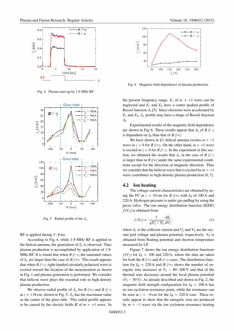
Fig. 6 Magnetic field dependence of plasma production.
the present frequency range, Ez of m = +1 wave can beneglected and Er and Eθ have a center peaked profile ofBessel function J0 [5]. Since electrons were accelerated byEr and Eθ, Jis profile may have a shape of Bessel functionJ0.
Experimental results of the magnetic field dependenceare shown in Fig. 6. These results appear that Jis of B //−zis dependent on IB than that of B //+z.
We have shown in §3, helical antenna excites m = −1wave in z > 0 for B //+z. On the other hand, m = +1 waveis excited in z > 0 for B //−z. In the experiment in this sec-tion, we obtained the results that Jis in the case of B //−zis larger than in B //+z under the same experimental condi-tions except for the direction of magnetic direction. Thuswe consider that the helicon wave that is excited by m = +1wave contributes to high-density plasma production [6, 7].
4.2 Ion heatingThe voltage-current characteristics are obtained by us-
ing the FC at z = 10 cm for B //+z with IB of 100 A and220 A. Hydrogen pressure is under gas puffing by using thepiezo valve. The ion energy distribution function (IEDF)f (V2) is obtained from
f (V2) ∝ 1√V2 − VS
dIC
dV2, (1)
where IC is the collector current and V2 and VS are the sec-ond grid voltage and plasma potential, respectively. VS isobtained from floating potential and electron temperaturemeasured by LP.
Figure 7 shows the ion energy distribution functionsf (V2) for IB = 100 and 220 A, where the data are takenfor both the B //+z and B //−z cases. The distribution func-tion for IB = 220 A and B //+z shows the number of en-ergetic ions increases at V2 ∼ 80 - 200 V and that of thethermal ions decreases around the local plasma potential(V2 ∼ 50 V). As already described and shown in Fig. 2, themagnetic field strength configuration for IB = 100 A hasno ion cyclotron resonance point, while the resonance canbe seen at z = −8 cm for the IB = 220 A case. These re-sults appear to show that the energetic ions are producedby m = −1 wave via the ion cyclotron resonance heating
3406032-3

Plasma and Fusion Research: Regular Articles Volume 10, 3406032 (2015)
Fig. 7 The ion energy distribution function under gas puffing.
Fig. 8 The ion energy distribution function at 20 mTorr hydro-gen pressure.
process.On the other hand, when B //−z, there is little differ-
ence of IEDF f (V2) at IB of 100 A and 220 A by compar-
ison with B //+z. Thus this result appears that ion heatingwas not performed because wave excited in z > 0 is notm = −1 but m = +1. Hence m = −1 wave play a major rolein ion cyclotron resonance heating. Furthermore we cansay that this ion acceleration is caused by not double layeracceleration but ion cyclotron resonance heating. Since itis considered that the double layer acceleration does notdepend on the direction of magnetic field.
In addition, we observed the ion energy distributionfunction by FC at z = 20 cm when IB is 100 A and 220 A at20 mTorr hydrogen gas pressure, as shown in Fig. 8. Un-like Fig. 7, IEDF f (V2) does not shift toward larger energyand broaden. This result is caused by charge exchange.When hydrogen pressure is at 20 mTorr, neutral gas densi-ties are much larger than the cases using the piezo valve.Therefore the ion is decelerated by charge exchange, andno significant difference in IEDF f (V2) between the casesof IB of 100 A and 220 A is found.
5. SummaryIn order to examine a new scenario of RF control of
plasma for electric propulsion using a single helical an-tenna, basic experiments have performed. When B //−z, Iis
is larger than the case of B //+z. On the other hand, whenB //+z, IEDF f (V2) shifts toward larger energy at magneticstrength of ion cyclotron resonance. This results indicatethat m = +1 wave is excited toward antidirection of mag-netic field, m = −1 wave is excited toward direction mag-netic field by using a right helical antenna. Using a singlehelical antenna, plasma production and ion heating is per-formed simultaneously. Thus helical antenna is effective toput a simple thruster into practice.
[1] F.R. Chang Diaz et al., Transaction on Fusions Science andTechnology 43, 3 (2003).
[2] E.A. Bering et al., Adv. Space Res. 42, 192 (2008).[3] Y. Yasaka et al., J. Propulsion and Power 28(2), 364 (2012).[4] R. Kinoshita et al., 23rd ITC (2013) P2-42.[5] S. Shinohara et al., Jpn. J. Appl. Phys. 34, L1571 (1995).[6] Y. Yasaka et al., J. Appl. Phys. 33, 5950 (1994).[7] S. Shinohara et al., Plasma Phys. Control. Fusion 37, 1015
(1995).
3406032-4