studio air : journal a + b
DESCRIPTION
Architecture Studio Air at The University of Melbourne Semester 2 2015TRANSCRIPT
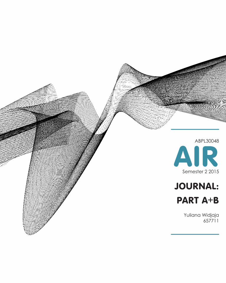
AIRSemester 2 2015
JOURNAL:
PART A+BYuliana Widjaja
657711
ABPL30048


TABLE OFCONTENTS
Introduction
Part A Conceptualisation
A.1 Design FuturingA.2 Design ComputationA.3 Composition / GenerationA.4 ConclusionA.5 Learning OutcomesA.6 Appendix: Algorithmic Sketches

Hello.Hi I’m Yuliana, a third year architecture student at the University of Melbourne. I was born and grew up in Indonesia and I’ve spent these last 3 years in Melbourne to pursue my passion.
My interest in architecture arose from my keen enthusiasm in crafts and Physics. It developed as my Dad, who works as property developer - once brought me to his work and I enjoyed the multidisciplinary work-ing environments of construction industry. From that point, I realised that Architecture would be the per-fect field for me as it combines all my interests into one.
Apart from being a student, I’m an adrenaline junkie and I have ticked skydiving, bungee jumping, and riding extreme roller coasters off my bucket list, yay! This may appear irrelevant to architecture, but it has changed the way I see things. I learned to dare to take any risk, for you will never know untill you try, and in the end you will only regret the chances you did not take.
Well, learning Software tools such as Rhino and Grasshopper is definitely out of my comfort zone. I just started to learn software when I was in first year university. From that time my skills developed progressively as I used them in my previous studios. I learned a lot from Studio Earth and Water, and I am looking for-ward to taking a more advanced computerized design approach in Studio Air since I believe that creativ-ity starts when you are not afraid of exploring new things.
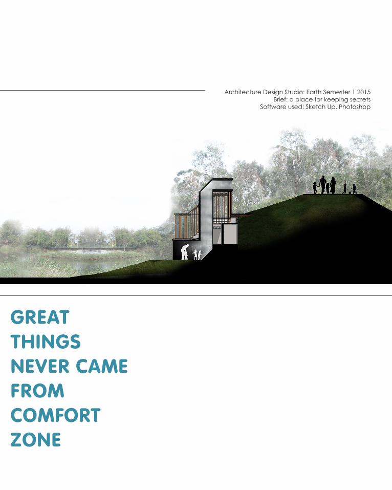
Architecture Design Studio: Earth Semester 1 2015Brief: a place for keeping secrets
Software used: Sketch Up, Photoshop
GREAT THINGSNEVER CAMEFROMCOMFORTZONE


[A]CONCEPTUALISATION

Figure A1.1 The City of Dubaihttp://www.netflights.com/media/189038/dubai_01_681x298.jpg (accessed 10 August 2015)
[A.1]DESIGN FUTURING

Design is shifting towards sustainability since people are aware that we have reached a stage where the amount of resources required to sustain the human population exceeds what is available.1
The above pictures show a Ski Dubai in The United Arab Emirates. This is an example of unsustainable practice since they have wasted huge amount of energy to maintain the ice from melting in the middle of desert temperature. Instead of creating buildings that are “alien” to the surrounding environments, architects should integrate social and the environment when designing
The word architect originates from Greek arkhitekton meaning ‘director of works’. Therefore architects play a big role in directing the future as they are - as the Greek definition of architect (arkhitekton) sug-gests - the ‘chief of buildings’.
The invention of computational approach might be a tool to help architects design buildings that incor-porate with surrounding environments and social needs. The following precedents show how architects integrate the surrounding natural environment in their design.
Figure A1.2 Interior of Ski Dubaihttp://www.orbittourism.ae/wp-content/uploads/2015/05/ski3.jpg
1 Tony Fry, 2008, Design Futuring: Sustainaibility, Ethics, and New Practice (Oxford: Berg): 1.


[1]Endesa PavilionBarcelona, 2011 Areti Markopoulou and Rodrigo Rubio
Figure A1.3 The southwest facade of Endesa Pavilionhttp://www.archdaily.com.br/br/01-74952/pavilhao-endesa-iaac
1 Areti Markopoulou and Rodrigo Rubio, “Smart living Architec-ture: Solar Prototype”, Constructions: an Experimental Approach to Intensely local Architecture 85, 2 (2015), 129.

Figure A1.4 Endesa Pavilion Southwest elevationhttp://www.archdaily.com.br/br/01-74952/pavilhao-endesa-iaac
CONTRIBUTION TO THE IDEA
In Design Futuring, users and the envi-ronment should be integrated in the design because designers design for them.
Endesa Pavilion is a perferct prec-edent of sustainable design. The form of Endesa Pavilion follows the data of the solar path of their specific sites in Barcelona. As a result, the PV panels attached can generate doubled the energy required in the building. This is indeed what design future is looking for, as the resources generated out-weigh the human needs.1
EXPANDING FUTURE POSSIBILITIES
The logic of the algorihm is gener-ated from the sun path diagram of the specific site. This means that the same algorithm can be applied to any coun-tries by adapting the parameter of Sun Path data in the specific site.
The form clearly indicates how the log-ic works. As Barcelona is located in the northern hemisphere, thus the south side is more likely to get direct sunlight. For this reason, the southwest side of the pavilion has the most PV panels, to maximise the energy generated.

Figure A1.5 Endesa Pavilion sectionFigure A1.6 Endesa Pavilion components
http://www.archdaily.com.br/br/01-74952/pavilhao-endesa-iaac
“Parametrically designed, it reacts to the data of its specific solar site, and via its flexible solar cells generates twice as much energy as it consumes.” 1 Areti Markopoulou and Rodrigo Rubio, “Smart living Architec-
ture: Solar Prototype”, Constructions: an Experimental Approach to Intensely local Architecture 85, 2 (2015), 129.
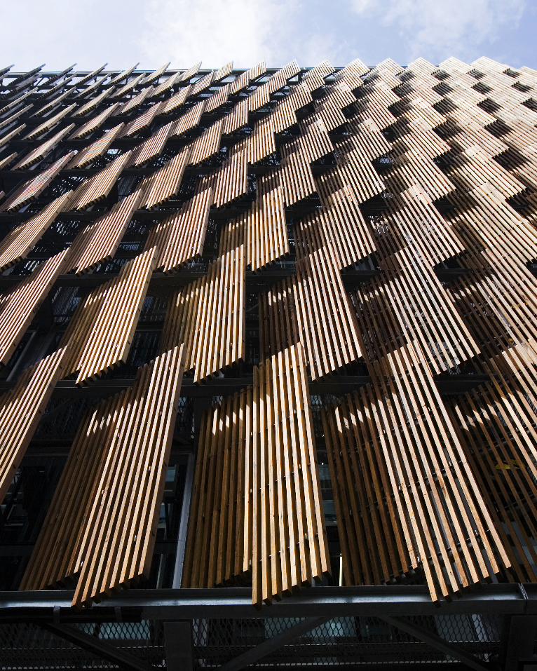

[2]CH2 BuildingMelbourne, 2004DesignInc Architects
Figure A1.7 The west facade of CH2 Buildinghttp://www.archdaily.com/395131/ch2-melbourne-city-council-house-2-designinc
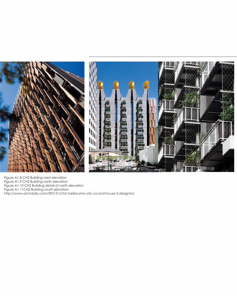
Figure A1.8 CH2 Building west elevationFigure A1.9 CH2 Building north elevationFigure A1.10 CH2 Building detail of north elevationFigure A1.11CH2 Building south elevationhttp://www.archdaily.com/395131/ch2-melbourne-city-council-house-2-designinc

CH2 Building is a green building that achieve 6 Star Green Star Building. The design of this building
is generated from the objective to maximise the wellbeing of its occupants (Indoor Environment
Quality). This approach is a characteristic of De-sign Future, as sustainability looks after the people
as well as the environment.
From the images on the left, it is evident that the facade is treated differently. The decision of each
treatment is based on the surrounding environ-ments to maximise passive design thus minimising
the energy consumed by the building.
Melbourne is located in the southern hemisphere, thus the northern facade gets most direct sun
light. For this reason, the window is getting smaller as it goes to the top of the building, so that oc-
cupants at the top do not get too much sunlight. Furthermore, the amount of afternoon sunlight
that gets into the building can be adjusted using operable timber panels in the western facade.
1 City of Melbourne. About CH2 Building, accessed 10 August 2015, from https://www.melbourne.vic.gov.au/Sustainability/CH2/aboutch2/Pages/AboutCH2.aspx

[A.2]DESIGN COMPUTATION
Figure A2.1 TheThe curvilinear programmed wall by Gramazio & Kohlerhttp://gramaziokohler.arch.ethz.ch/web/e/lehre/81.html

Design is shifting towards sustainability since people are aware that we have reached a stage where the amount of resources required to sustain the human population exceeds what is available.1
The above pictures show a Ski Dubai in The United Arab Emirates. This is an exam-ple of unsustainable practice since they have wasted huge amount of energy to maintain the ice from melting in the middle of desert temperature. Instead of cre-ating buildings that are “alien” to the surrounding environments, architects should integrate social and the environment when designing
The word architect originates from Greek arkhitekton meaning ‘director of works’. Therefore architects play a big role in directing the future as they are - as the Greek definition of architect (arkhitekton) suggests - the ‘director of works’.
The invention of computational approach might be a tool to help architects de-sign buildings that incorporate with surrounding environments and social needs.
1 Peters, Brady. (2013) ‘Computation Works: The Building of Algorithmic Thought’, Architectural Design, 83, 2, pp. 08-15
Computerization vs Computational
It seems that the terms computerization and computation are often used interchangeably as the same thing, while in fact they have com-pletely different meaning. Computerization is when one uses computer only for drafting tool, but the design method itself is still analog. On the other hand, computational technique makes use of computer capabil-ity to assist designers in solving complex issues, such as material optimi-zation, digital materiality, digital fabrication, and efficient construction process1.
The following precedents show how architects integrate computational technique in their design process, allowing sophisticated solution to complex issues, which are hardly possible to be done manually.

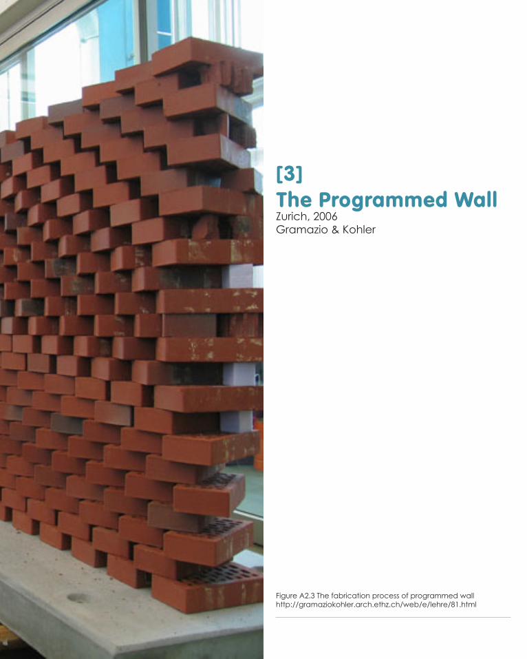
[3]The Programmed WallZurich, 2006Gramazio & Kohler
Figure A2.3 The fabrication process of programmed wall http://gramaziokohler.arch.ethz.ch/web/e/lehre/81.html

The first precedent of design computation is “The Programmed Wall” by Fabio Gramazio and Matthias Kohler. It was a research project in 2006 that investigate the design potential for brick using digital fabrication. At that time, it was considered a radical invention as it resolved the limited flexibility of brick modules to produce fluid form. It would be extremely difficult to produce complex curvilinear walls if using traditional design and construction methods since mason cannot lay the brick as accu-rately as computer does, even with extra tool.
Brick masonry construction has declided significantly in western countries due to high cost of masonry labor and long duration of construction pro-cess that causes even higher cost. 2 Thus, this research may brick back the popularity of masonry construction since it has solved the shortcom-ings of this method.
In addition to faster and relatively cheaper construction process, digital fabrication allows designers to supervise the construction process since the robot is controlled digitally.
In conclusion, there has been a change in the use of computer in design and construction indusry. Previously, computer was only used as a tool to digitize drawings, but today designers use computer to do the construc-tion process, allowing accurate result and more resolved outcome.
"A robot is not only quicker, more precise, and more pro-ductive, but it also enables complex designs that are im-possible for a human to build with that level of accuracy."1

BASIC LOGIC
Gramazio and Kohler started the design by creating possible iterations of curvilinear surfaces (Figure A2.4). Next, they create the logic based on procedural logic of laying brick in traditional masonry.3
“A brick is laid to another brick, shifted, and perhaps rotated until the end of a row is reached. The next row is then shifted by half of the brick width, and the previous procedure is repeated, and so on until the desired height is reached.”4
This logic is applied to both vertical and horizontal direction, which eventually create a curvilinear wall (Figure A2.5).
1 Gramazio, F., & Kohler, M. (2008). Towards a digital material-ity. In B. Kolarevic, & K.R. Klinger, Manufacturing material effects: rethinking design and making inarchitecture (p 113). NewYork: Routledge.
2 Kareem El Sayed Mouhammad. “Potential Innovative use of conventional building materials: Case Studies on Masonry and Stone Constructions”, Alexandra University. http://www.aca-demia.edu/1454683/Innovative_use_of_conventional_materials
3 Nick Dunn, Digital Fabrication in Architecture (London: Laurence King Publishing, 2012),53.
4 Gramazio and Kohler, 2008.
Figure A2.4 The curvilinear iterations http://gramaziokohler.arch.ethz.ch/web/e/lehre/81.html
Figure A2.5 The logic is applied in vertical and horizontal direction http://gramaziokohler.arch.ethz.ch/web/e/lehre/81.html


[4]ICD/ ITKE PavilionStuttgart, 2010Achim Menges
Figure A2.6 ICD/ITKE Research Pavilion 2010http://icd.uni-stuttgart.de/?p=4458

ICD Pavilion is a research project by University of Stuttgart that uses inno-vative design process that is more efficient than in the past. In conven-tional design process, the form was generated first before moving to ma-teriality. In contrast, the designers of ICD Pavilion started the project by studying the behavior of the material they would like to use. The test the bending stress of the material physically (Figure A2.8). Next, the results were then transformed into algorithms that would determine the form. After setting the logic, the designers used software such as FEM Model-ling to let computer generate the possible forms that satisfy the logic.1
This computational design technique is far more efficient than the con-ventional design process because the final form is structurally efficient since the form is generated from the behavior of the material itself.
This precedent shows that computational design technique allows de-signers to increase the efficiency in construction using the natural behav-ior of material using parametric algorithms.
1 Moritz Fleischmann, Jan Knippers, Julian Lienhard, Achim Menges and Simon Schleicher, “Material Behaviour: Embedding Physical Properties in computational design Processes”, Material Computation: Higher Integration in Morphogenetic Design, Architectural Design 82,2 (2012): 44-51.
Figure A2.7 FEM modelling showing the bending stress across the formhttp://icd.uni-stuttgart.de/?p=4458

Figure A2.9 Bending Stress data analysishttp://icd.uni-stuttgart.de/?p=4458
Figure A2.8 Physical Experiment on bending be-havior of material plywood stripshttp://icd.uni-stuttgart.de/?p=4458

Figure A3.1 The subdivided columns by Michael Hansmeyerhttp://www.michael-hansmeyer.com/projects/columns.html?screenSize=1&color=1
[A.3]FROM COMPOSITION
TO GENERATION

Not only can computer assist human in digital fabrication and construction, but also in generating forms. Generation is one of computational techniques that allow architects to explore forms during design process. So instead of com-posing the geometry from the start, designers create a constructive logic and let computer generates the forms, thus the outcome is emerging beyond the intellect of designers.
To use generative approach, architects need to generate an algorithm based on certain logic. The key feature of algorithm is that it is made of definite set of operations and is easy to follow1. The movement of each particle is af-fected by the relationship to its neighbors, and at the same time is affecting how the neighboring particles move. This simple rule results in unpredictable and infinite number of possible forms and the architect can then choose the best iterations amongst them.
However, despite the above advantages of using generative design approach in the design process, there are also disadvantages associated with it. One of the major problems caused by digital architecture is that it creates gap between the architects and the end products. This happens because some architects are lacking of algorithmic scripting skills, thus often they invite scripting experts to optimize the initial concepts they had2. In this case, the archi-tects can only contribute to the concepts and overall shape of the building, but they cannot involve during the form generation process. Therefore it is necessary for architects to develop their knowledge in scripting to catch up with the trend of digital architecture.
The precedent in the previous section (A2 Design Computation) - the programmed wall- has given an idea of how the wall is generated from algorithm. The following precedents – Brass Swarm and Subdivided columns – will further demonstrate how architects can generate a complex from a basic logic using parametric design approach.
1 Definition of ‘Algorithm’ in Wilson, Robert A. and Frank C. Keil, eds (1999). The MIT Encyclopedia of the Cognitive Sciences (London: MIT Press), pp. 112 Asterios Agkathidis and Elizaveta Edemskaya, “Vladimir Shukhov: A Critical Review on Digital Architecture,” eCAADe 33 (2015): 1.


[5]Agent Bodies + Swarm IntelligenceMelbourne, 2004Kokkugia
Figure A3.3 Swarm Composite Kokkugia Researchhttp://www.kokkugia.com/woven-composites

+
SWARM INTELLIGENCEFigure A3.4 Swarm Intelligence Kokkugia Researchhttp://www.kokkugia.com/filter/swarm-intelligence/swarm-intelligence
Agent BodiesFigure A3.5 Agent Bodies Kokkugia Researchhttp://www.kokkugia.com/filter/agent-bodies/agentbodies

=
Ronald Snooks is a Melbourne architect who has strong interest in computational design processes and robotic fabrication techniques. In his experimental architecture research called Kokkugia, he and his partner Robert Stu-art- Smith explore generative design practices based on the logic of complex self-organizing behavior of systems1.
Two of the main research agendas that they are working on are Swarm Intelligence and Agent Bodies.
1. Agent Bodiesis multi-agent used to design complex tectonics. The logic of it came from the conceptualization of ant bridges, which demonstrates the interrelated geometry of ant bodies when forming Ant Bridge.
2. Swarm intelligenceis an algorithm that draws from the logic of collective behavior that happens intuitively, such as in flocking of birds and schooling of fish.
From these two logics, Ronald Snooks generate seven different forms, which are completely different one to another. It is interesting how simple logics can result in varied impressive results that you would not have ex-pected that they all come from the same logic. Two of the researches are Brass Swarm (Figure A3.6) and Com-posite Swarm, shown in the previous page (FigureA3.3).
Brass SwarmFigure A3.5 Brass Swarm Prototype in Shanghai 2015http://www.kokkugia.com/filter/agent-bodies/brass-swarm
1 Kokkugia, “Research Agendas”, accessed 9 August 2015, from http://www.kokkugia.com/filter/research/research-agendas


Figure A3.10 Subdivided columns by Michael Hansmeyerhttp://www.michael-hansmeyer.com/projects/columns.html#20
[6]Subdivided ColumnsGwangju Design Bienalle, 2011Michael Hansmeyer
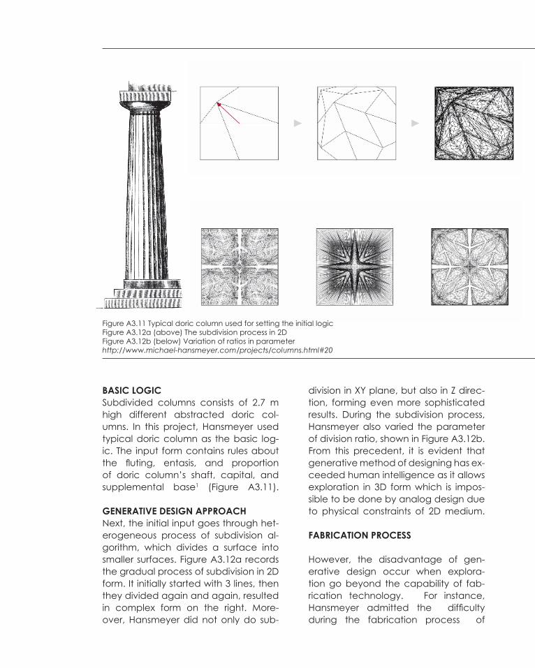
BASIC LOGICSubdivided columns consists of 2.7 m high different abstracted doric col-umns. In this project, Hansmeyer used typical doric column as the basic log-ic. The input form contains rules about the fluting, entasis, and proportion of doric column’s shaft, capital, and supplemental base1 (Figure A3.11).
GENERATIVE DESIGN APPROACHNext, the initial input goes through het-erogeneous process of subdivision al-gorithm, which divides a surface into smaller surfaces. Figure A3.12a records the gradual process of subdivision in 2D form. It initially started with 3 lines, then they divided again and again, resulted in complex form on the right. More-over, Hansmeyer did not only do sub-
division in XY plane, but also in Z direc-tion, forming even more sophisticated results. During the subdivision process, Hansmeyer also varied the parameter of division ratio, shown in Figure A3.12b. From this precedent, it is evident that generative method of designing has ex-ceeded human intelligence as it allows exploration in 3D form which is impos-sible to be done by analog design due to physical constraints of 2D medium.
FABRICATION PROCESS
However, the disadvantage of gen-erative design occur when explora-tion go beyond the capability of fab-rication technology. For instance, Hansmeyer admitted the difficulty during the fabrication process of
Figure A3.11 Typical doric column used for setting the initial logicFigure A3.12a (above) The subdivision process in 2D Figure A3.12b (below) Variation of ratios in parameterhttp://www.michael-hansmeyer.com/projects/columns.html#20

The architect designs a process that produces a column, rather than designing a column directly. Michael Hansmeyer
“
“
the subdivided columns for the Gwangju Design Biennale in 2011.
The columns were fabricated layer by layer using 2700 sheets of 1mm card-board2. The sheet was individually cut by laser cutter, and stacked around a common core to hold them together. The detailed curvy form makes it ex-tremely difficult to be 3D printed as the parts are prone to breaking off.
From Michael Hansmeyer’s experi-ence, we learn that during genera-tive design process, it is crucial to think of constructability as the limit of the exploration in generative process.
1 Michael Hansmeyer , “Subdivided Columns - a New Order”, ac-cessed 10 August 2015, from <http://www.michael-hansmeyer.com/projects/columns_info.html?screenSize=1&color=1>.
2 Ibid
Figure A3.13 Several iterations of subdivided columnsFigure A3.14 Fabrication process of subdivided columns in Gwangju Design Biennale 2011http://www.michael-hansmeyer.com/projects/columns.html#20

[A4]Conclusion
In conclusion, we are now living in the era where the human population is significantly increasing, while on the other hand the resources are decreasing. Due to concern of insufficient amount of resources to sustain the needs of generations to come, human,
inclusing designers, need to change their behavior and way of thinking. Design futuring looks towards sustainability, in which the design must incorporate with the environment
so that it minimises negative impacts to the environment.
Computational approach, unlike computerization, uses computer as a tool in assisting designers to analyse and solve complex problems, thus giving the most efficitent solu-tion to minimise the impact on environment. For instance, The position of PV panels in Endesa pavilion is based on the computational data of sun path in Barcelona. The ar-
chitect used parametric design to create the form that can optimise the input of radia-tion energy to every single PV panels. This is impossible to be done manually without the aid of computer, therefore computational technique is critical for designers to achieve
Design Future.
In addition to that, computational architecture includes generative design approach which enable designers to generate complex forms. With this method, instead of com-posing the geometry from the start, designers start with making algorithm that makes the logic of movement. Next, the computer will create infinite number of possible out-comes based on the logic, and designers can choose several iterations that work and they can develop them even further. This allow designers to come up with unexpected
yet interesing discoveries.

Within these three weeks, I realised that computational technique really is a beneficial approach in designing. It brings many disadvantages, such as for exploring new mate-rial, material optimisation, and increasing efficiency of construction. More importantly, it helps architects to generate forms beyond 2 dimensional medium which was previo-ulsly a limitation when using analog design method. Generative design approach al-
lows designers to come up with complex forms beyond the imagination of the design-ers themselves.
In some cases the exploration may go too far and create issue during the fabrication , such as in Hansmeyer subdivided columns project. However, I believe that in the future
the fabrication technology will get more advanced and able to accomodate the exploration of generative design approach.
As the advantages overcome the disadvantages, I believe that generative design approach will replace the analog design approach and become the trend in years to
come (or even now). For this reason, I think it is important for me to learn algorithmic software such as Grasshopper for my future career in architecture practice.
[A5]Learning Outcome
[A6]Appendix:
Algorithmic Sketches


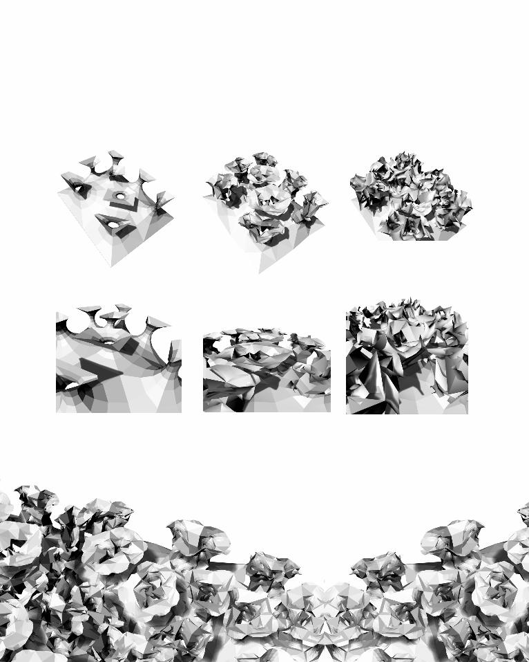
These are the first attempt of my exploration on Grasshopper. At this stage, due to my limited understanding on Grasshopper inputs, the exploration is based on trial and
error, thus the results are random and some of them are failed.
I played a lot wih triangulation inputs, such as octree, voronoid, and metaball. I combined the triangulation inputs with surface commands such as pipes and lofts
to create geometry.
This exercise has given me a better understanding on how computational design strategy in the precedents work. Different inputs and variable parameters can result
in various complex iterattions, which often create unpredictable yet interesting outcome.
Week 1

In the second trial, I tried to experiment with surface panelling. I create two different geometries, which are circles and lines,,as
the panels on lofted curves.
I did not expect the outcome would be this interesting. The panels create shadows when rendered, causing even more dramatic
effect.
Week 2

In this exercise, I experiment with contours and geodesic inputs. From the contour lines, I also try to divide it into points, and use octree, shown at the bottom right images. However, this experiment failed because the points are too close to one another, thus the boxes are concentrated to one area only.
I also played with changing the contours in X, Y, and Z direction and it came up with interesting result (top right image)
I look forward to continue learning Grass-hopper throughout the rest of this semester and I believe that this will help my design process in the future.

Week 3

Fry, Tony. 2008. Design Futuring: Sustainaibility, Ethics, and New Practice (Oxford: Berg).
Markopoulou, A. & Rubio, R. “Smart living Architecture: Solar Prototype”, Constructions: an Experimen-tal Approach to Intensely local Architecture 85, 2 (2015).
City of Melbourne. About CH2 Building, accessed 10 August 2015, from https://www.melbourne.vic.gov.au/Sustainability/CH2/aboutch2/Pages/AboutCH2.aspx
Gramazio, F., & Kohler, M. (2008). Towards a digital materiality. In B. Kolarevic, & K.R. Klinger, Manufac-turing material effects: rethinking design and making inarchitecture (p 113). NewYork: Routledge.
Mouhammad,K. “Potential Innovative use of conventional building materials: Case Studies on Masonry and Stone Constructions”, Alexandra University. http://www.academia.edu/1454683/Innovative_use_of_conventional_materials
Dunn, N. Digital Fabrication in Architecture (London: Laurence King Publishing, 2012),53.
Fleischmann, M. et. al, 2012. “Material Behaviour: Embedding Physical Properties in computational design Processes”, Material Computation: Higher Integration in Morphogenetic Design, Architectural Design 82,2, pp 44-51.
Peters, Brady. (2013) ‘Computation Works: The Building of Algorithmic Thought’, Architectural Design, 83, 2.
Definition of ‘Algorithm’ in Wilson, Robert A. and Frank C. Keil, eds (1999). The MIT Encyclopedia of the Cognitive Sciences (London: MIT Press).
Agkathidis, A. & Edemskaya, E. 2015. “Vladimir Shukhov: A Critical Review on Digital Architecture,” eCAADe (33).
Kokkugia, “Research Agendas”, accessed 9 August 2015, from http://www.kokkugia.com/filter/re-search/research-agendas.
Hansmeyer, M. “Subdivided Columns - a New Order”, accessed 10 August 2015, from <http://www.michael-hansmeyer.com/projects/columns_info.html?screenSize=1&color=1> .

Bibliography


[B]CRITERIA DESIGN

Figure B1.1 The ICD/ITKE Pavilion 2013/2014http://icd.uni-stuttgart.de/wp-content/gallery/rp2013-14-icd-itke/folie24.jpg(acessed 20 September 2015)
[B.1]RESEARCH FIELD:
BIOMIMICRY

As discussed in the previous chapter, architecture is now moving towards sustainability as human has caused huge damage to nature in the past and if we continue to do that, the future generations wouldn’t be able to have enough resources to survive.
Fortunately, the best precedents for the solution is just around us: biological entities. Janine Benyus claims that “(w)hen we look at what is truly sustain-able, the only real model that has worked over long periods of time is the natural world.” The reason is because nature has been striving for millions of years, yet its existence doesn’t bring negative impact to its surrounding.
The term biomimicry and biomimetics are often used interchangeably, while in fact they are slightly different. Michael Pawlyn defines biomimicry as “mim-icking the functional basis of biological forms, processes, and systems to pro-duce sustainable solutions”2. In contrast, biomimetic is is a general term for imitating the elements of nature. The main difference here is that biomimicry does not only generate biomorphic forms to imitate nature’s appearance, but more importantly learning from its behavior to find out a solution for more sustainable practices.
Therefore, I will use biomimicry as the foundation of my design by incorpo-ratng nature’s characteristics as the solution for the issues on Merri Creek.
1. Janine Benyus, Ted Talk Biomimicry in Action, July 2009, http://www.ted.com/talks/janine_benyus_biomimicry_in_action?language=en2. Michael Pawlyn, “Biomimicry in Architecture”(London: RIBA Publishing, 2011), 2
"When we look at what is truly sustainable, the only realmodel that has worked over long periods of time is the natural world. "1 -Janine Benyus-


[1]Palazzetto dello Sport
Pier Luigi Nervi Rome, Italy, 1962
Michael Palwyn in his book “Biomimicry in Architecture argues that nature is able to use material effeciently due to its evolved ingenuity of form, such as folding, vaulting, and inflation. Nature continuously refining its structure to be able to survive, so the characteristics that we can see today is the best structure nature can be throughout the entire process of evolution. For that reason learning from the nature surround us today will give us inspiration for creating a sustainable and effective structure.
Design Implication & Opportunities
In this example, Nervi was inspired by the efficient use of network of ribs in Amazon water lily that are able to stiffen large area of leaf without adding significant thickness. In this project, Nervi combined the structural strength pro-duced by the interconnecting ribs as well as dome action to support wide thin planar surface. 1 As a result, he cre-ated extremely efficient structures and minimised the overall material cost.
Fabrication
In this project, Nervi makes use of the advantage of his invention of reinforced concrete called ‘ferro cemento’ which is elastic and strong thus allowing him to create complex form.
1. Michael Pawlyn, “Biomimicry in Architecture”(London: RIBA Publishing, 2011), 9
(left) The Oculus of Palazzetto dello Sport. http://www.architectural-review.com/Journals/2012/01/30/e/k/j/020a-palazzetto-IMG_7467.jpg
a. The Oculus in planhttps://www.pinterest.com/pin/569353577864421959/b. Inspired by the Amazon giant water lily leafMichael Pawlyn, “Biomimicry in Architecture”(London: RIBA Publishing, 2011), 8.c. Section of Palazzetto dello Sport. http://www.urbipedia.org/images/5/51/Palazzetto_dello_sport.Planos1.jpg
(b)(a) (c)
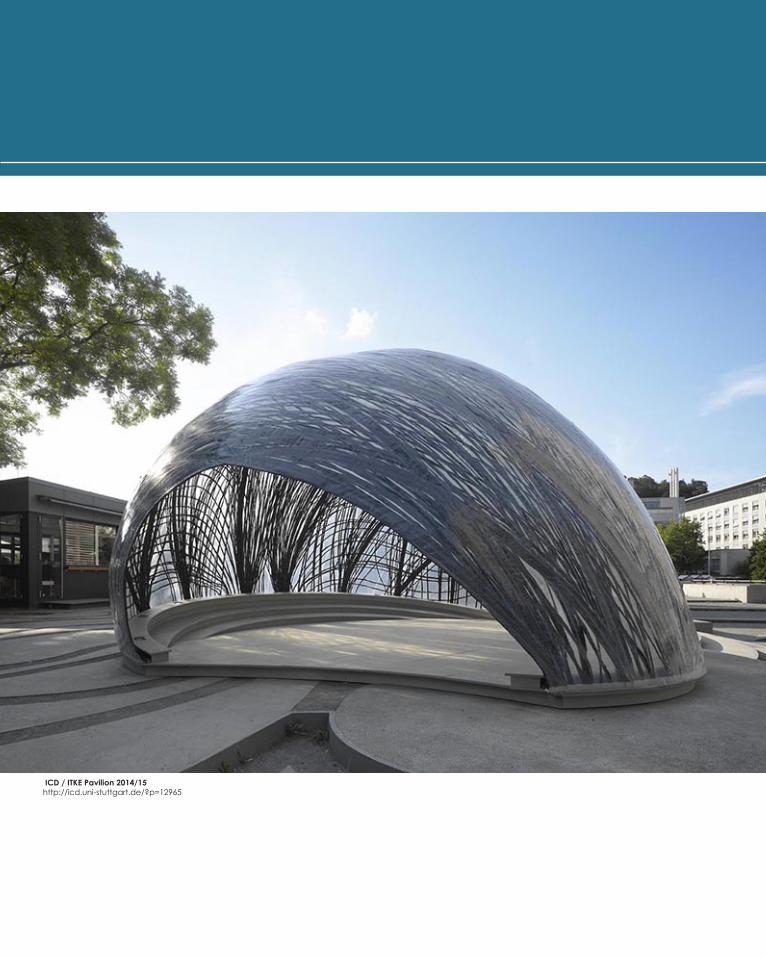
ICD / ITKE Pavilion 2014/15http://icd.uni-stuttgart.de/?p=12965

[2]ICD/ITKE Pavillion
2014/2015Inst. for Computational Design (Prof. Menges) Inst. of Building Structures &
Structural Design (Prof. Knippers)
Design Implication & Opportunities
This project was inspired by the underwater nest construction of the water spider. As water spider spends most of its life under water, they build a reinforced air bubble to survive. To begin with, the spider builds a horizontal sheet web as the base for putting the air bubble. Next, the air bubble is progressively reinforced by laying a hier-archical arrangement of fibers from within(shown in figure a). This results in a stable structure that can withstand mechanical stresses, including changing water currents, thus providing a safe and stable habitat for the spider.
Fabrication
ICD/ITKE Pavilion 2015 takes this natural production process to create efficient fiber-reinforced struc-tures using industrial robot.
Initially, the robot is placed within an air supported membrane envelope made of ETFE. Next, the robot is programmed to reinforce the inside with carbon fiber to gradually stiffened the structure into a self-supporting structure. The carbon fibers are only applied to area that require structural reinforcement, which results in a resource efficient construction process.
(c)
(a) Microscopic image of Diving Bell Water Spider (Agyroneda aquatica) nesthttp://icd.uni-stuttgart.de/?p=12965
Robotic placement of carbon fiber reinforcement layers Various fiber reinforcement strategieshttp://icd.uni-stuttgart.de/?p=12965
(b) Water Spiderhttp://icd.uni-stuttgart.de/?p=12965
1. Universitat Stuttgart, accessed 20 September 2015, http://icd.uni-stuttgart.de/?p=12965.

Figure B2.1 Biothing Seriossi Pavilionhttp://farm3.static.flickr.com/2637/3709156721_4c01a33f6f_b.jpg(acessed 20 September 2015)
[B.2]CASE STUDY 1.0:
Biothing Seriossi Pavilion


1 2 3 4 5 6 7 8
a. Points
b. Curves
c. Hexagonal Grid
d. Sine and Cosine Function

1 2 3 4 5 6 7 8

B.2. Selected Outcome
Selection Criteria
I’m planning to design a fishway at Dight Falls, therefore the requiremen for the brief is to create a pathway that can
slower down the flow of the water with low slope, so that fish can swim from upstream to downstream, and vice versa.
Therefore, my selection criteria is a form that has rough surface, to achieve my intention in slowing down the water
movement. However, the surface can’t be too sharp be-cause otherwise it may harm the fish.
I chose the iterations on the left as the best 4 because these form have successfully created rough surface.
Speculation upon design potential
The iterations might help in generating rough form which I may attach on the wall of the fishway.
However, fabrication becomes a big issue since the iterations are all in the form of lines, thus I may need to think of materi-als that are flexible and thin, such as using fibre. Furthermore,
it has to be waterproof since my design will be placed underwater.

1
I like the shape in the middle that ap-pears like a mountain. However, the top is too shape so I might need to change it to smoother shape
2
This, again, appears like mountainous sur-face. In comparison to iteration , this shape is smoother, however it is separated to one another so it looks like segmented.
3
This shape reminds me of a coral that is soft and flexible. I might be able to use this shape to mimick the natural coral which also slow down water current.
4
The final iteration is the most unique one. I generated this form by combining sine and cosine graph together. In relation to the brief, this might be the sectional view of a fishway tunnel, which would be interesting!

[B.3]CASE STUDY 2.0:
Flora Form Florescence Jewelryby Nervous System
Figure B3.1 Floraform jewelryhttp://n-e-r-v-o-u-s.com/projects/sets/floraform/

AboutFloraform is a project developed by Nervous system. They got inspiration from the biomechanics of growing leaves and blooming flowers. This project mimicks the development of natural surfaces through differential growth. The simulation results in a curly unique form which then are 3d printed to make jewelry and sculpture .
I chose this particular project because this may be the solution to my agenda, which is to create a rough and uneven surfaces.
Figure B3.1 Floraform inspirationhttp://n-e-r-v-o-u-s.com/projects/sets/floraform/

Set 6 curves Populate Geometry+
Construct Delaunay Triangulation Mesh
N.B. the edges of the curve needs to have more points (to achieve
curly effect)
Run Kangaroo Solver
Input:- Sphere Collide
- Show-Smooth
- Length (Line)
1 2 3
B.3. The Process

Select The edges of the mesh using Cull Pattern, then subdivide using
Weaverbird’s Split Triangles Subdivi-sion to get more points
Repeat procedure 3 (Kangaroo Solver) to achieve more curly
effect
BakeRepeat the process several times
and combine the mesh
4 5 6

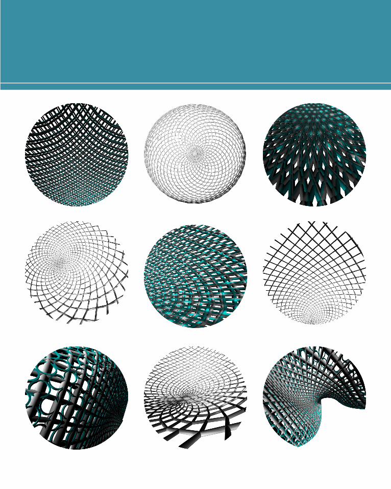
[B.4]TECHNIQUE: DEVELOPMENT


Species 1: Torus Delaunay Mesh
1 2 3 4
a
b
c

Species 1: Torus Delaunay Mesh
Species 2: Cone Delaunay Mesh
1 2 3 4
a
b
c

Species 3: Kangaroo generated Mesh
1 2 3
a
b
c

Species 3: Kangaroo generated Mesh
Species 4: Lines
1 2 3 4
a
b
c
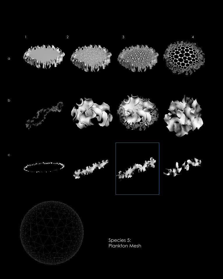
Species 5: Plankton Mesh
1 2 3 4
a
b
c

B.4. Selected Outcome
Species 5: Plankton Mesh
In this part, I’m still aiming to generate uneven and rough form. The outcome produced is more desire-able than in part B.2. By using Kangaroo plugin, I’m able to generate form based on physics logic sphere collide. The colllision of every single sphere create a curly effect. The most successful one is C because it create a curly strips that I can adopt to my fishway design.

[B.5]TECHNIQUE: PROTOTYPE

For the prototype, I 3D print one of my successful itera-tion using powder printer which is waterproof.
I experiment the water movement in 2 different surface. First I put my 3DPrint form into the the bottle, forming rough surface. When I put dye into the water, I can see that the dye was hold by the rough thus it moves slower than in smooth surface.
This indicates that my initial speculation was correct and it should be able to slower down the water move-ment in the fishway.
1. Powder Print the model
2. Prepare Red Dye 3. Place the model in the bottle
4. Pour tap water into the bottle
5. Put a drop of red dye into the water
5. Open the bottle lid to let water flow
6. The Red Dye indicate the flow of water
7. The model has suc-cessfully slowed down the water flow

Distribution Map of Australian Grayling
Source:Australian Government, Department of Environment, 2015http://www.environment.gov.au/cgi-bin/sprat/public/pub-licspecies.pl?taxon_id=26179
Source:Melbourne Water, 2015
Client:
AustralianGrayling
“ Grayling have undergone severe de-clines in most of their known habitats and are now listed as vulnerable at a State and National level.” Melbourne Water
[B.6]TECHNIQUE: PROPOSAL


a timber structure was built to provide water to the Melbourne Flour Milling Company.
The timber weir was broken thus require new structure
the original timber piles were capped by concrete, replacing
the timber deck
Dight Falls TimelineSource: Melbourne Water
1940 19681895

Melbourne Water realized that the weir was a barrier to fish mi-
gration, thus they constructed a rock fishway to allow fish to move
around the weir.
The rock fishway was partly ef-fective thus they built vertical slot
fishway
1993 2012 2015
?

Digh
ts Fa
lls - A
rtist Im
pres
sion
62
5
4
1
3
1 2 3
4
5 6
Exit
Entry
New Weir
The new weir will be similar in height, location and shape to the existing structure and will maintain a waterfall effect. Constructed of concrete and underpinned by bored piles, the proposed weir ties into the rock face on the southern bank of the river in the same location as the existing structure. On the northern bank it ties in, and connects to the fi shway, approximately two metres in front of the existing structure.
Vertical Slot Fishway & Viewing Platform
The vertical slot fi shway will allow fi sh to move past the weir. The fi shway features a gently sloped concrete channel divided to create a series of connected pools. The vertical slot fi shway will be landscaped into the river bank and covered by grates to protect fi sh from predators. The fi shway will also act as a platform for the community to view Dights Falls.
Interpretive Signage
Interpretive signage will provide the community with information about the fi shway.
Placed Rock
Carefully placed rock will be used to visually integrate the fi shway into the natural surrounds. The placed rock will also play an important role in allowing fi sh to swim up to the entrance of the vertical slot fi shway near the weir.
Landscaping
The area around the fi shway will be landscaped with native plants to help integrate the design with the surrounding park.
Concrete Access Path
A path will connect the existing mill race crossing with the fi shway viewing platform.
ARTIST IMPRESSION OF THE NEW WEIR AND FISHWAY AT DIGHTS FALLS
INTERNAL VIEW OF FISHWAY
INTERNAL PLAN VIEW
FISHWAY GRATES
FISH MOVEMENT UPSTREAM
Refer to Internal Plan View
30.8m
4.4m
Source: Melbourne Water
Diagram of the existing Fishway at Dight FallsDight Falls Weir and Fishway Project 2010-2012


Exploded Axonometric Diagram of major elements required in Fishway at Dight Falls
1. Compartments
2. Outer and inner walls
2. Base with slope 1:18

My design intention is to keep the major ele-ments that are necessary in Fishway as de-signed by the engineer, but transforming the wall shape maximise its efficiency.
A research of innovative fishway design by Mar-tin Mallen-Cooper, Brenton Zampatti, Ivor Stuart, and Lee Baumgartner in June 2008 concludes that
“Manipulating Turbulance by adding wall roughness in the vertical slot design can improve performance”
Previously they use PVC Pipes to achieve this, as shown in figure below. For this reason, instead of using PVC pipes, I want to change the wall tex-ture to achieve the same outcome but minimis-ing the cost and use of extra material.
Source:Innovative Fishway Design
by Martin Mallen-Cooper, Brenton Zampatti, Ivor Stuart, and Lee Baumgartner
June 2008

[B.7]LEARNING OBJECTIVES
& OUTCOMES

In the past 9 weeks in Air Studio, I have learned so much and my skills in using Rhino and grasshopper has improved significantly.
The research has made me have a better and clearer understanding of coputational design. Further-more, I found some precedents that are very useful in generating ideas and forms.
Now I’m able to create, manipulate, and design using parametric modelling. For instance, when I first look at the precedent of Floraform for my Case Study 2 project, I had no idea how to form such unique shape lilke that. Fortunately, by doing research and help from my tutor, I can successfully made similar shape. In the future I will keep learning to be more advanced in computational design which I found very useful.

[B.8]Appendix-
Algorithmic Sketches