studs': a squat-type defect in...
TRANSCRIPT

This is a repository copy of "Studs": a squat-type defect in rails .
White Rose Research Online URL for this paper:http://eprints.whiterose.ac.uk/43163/
Article:
Grassie, Stuart L, Fletcher, David I, Gallardo Hernandez, Ezequiel Alberto et al. (1 more author) (2011) "Studs": a squat-type defect in rails. Proceedings of the Institution of Mechanical Engineers, Part F: Journal of Rail and Rapid Transit , 226 (3). pp. 243-256. ISSN 0954-4097
https://doi.org/10.1177/0954409711421462
[email protected]://eprints.whiterose.ac.uk/
Reuse
Unless indicated otherwise, fulltext items are protected by copyright with all rights reserved. The copyright exception in section 29 of the Copyright, Designs and Patents Act 1988 allows the making of a single copy solely for the purpose of non-commercial research or private study within the limits of fair dealing. The publisher or other rights-holder may allow further reproduction and re-use of this version - refer to the White Rose Research Online record for this item. Where records identify the publisher as the copyright holder, users can verify any specific terms of use on the publisher’s website.
Takedown
If you consider content in White Rose Research Online to be in breach of UK law, please notify us by emailing [email protected] including the URL of the record and the reason for the withdrawal request.

“STUDS”: A SQUAT-TYPE DEFECT IN RAILS
Stuart L Grassie1, David I Fletcher
2, Ezequiel Alberto Gallardo Hernandez
3,
Paul
Summers4
1Abbauernring 1, 30900 WEDEMARK, Germany
2Department of Mechanical Engineering, University of Sheffield, Mappin Street,
Sheffield, UK S1 3JD
3 SEPI-ESIME-Instituto Politecnico Nacional, Zacatenco, Mexico
4 Tubelines Ltd, 15 Westferry Circus, LONDON, UK E14 4HD
ABSTRACT
In the mid-2000s a rail defect that was classified as a “squat” became increasingly

common on London Underground’s track. By 2006 there were about 600 of these and
they had become the Underground’s single most common rail defect. This defect
occurred almost exclusively on lines carrying relatively new rolling stock. The work
reported here was undertaken initially to characterize this defect, advise as to whether it
was indeed a squat and propose a hypothesis that explained its mechanism of formation.
The paper includes observations and measurements from track and initial results of
metallurgical analysis. The hypothesis for formation of the defects is presented, and
both similarities and differences are discussed between these defects and the classical
“squat”. The defect on London Underground appears to be the same as that described
by Marich and his colleagues in Australia and by Li and his colleagues in the
Netherlands. It is evidently not a rolling contact fatigue defect. In order to avoid
confusion arising from simple misuse of an established term, it is proposed that these
defects be given a different name, for which “stud” is proposed. Evidence to date is that
the “stud” is a significantly more benign defect than a “squat”.
Keywords: Squat, stud, rolling contact fatigue, rail, pearlitic steel
1 Introduction
A squat is a rolling contact fatigue (RCF) defect in rails whose characteristics are well
understood as a result of more than two decades of research from the mid-1970s,
primarily in Europe and Japan e.g. [1,2]. Squats are particularly dangerous defects

because if they are allowed to remain in track, the commonly develop into rail breaks.
For this reason railway systems are concerned about the presence of squats and ensure
either that rails are ground routinely to prevent small surface breaking cracks
propagating and to manage rail-wheel contact stresses, or that rails containing cracks
which have developed too deeply to be ground out are removed. The fact that squats to
date have been associated primarily with passenger and mixed traffic railways has
heightened an awareness of this hazard.
There is evidence that in the last 10-15 years a defect that shares many characteristics
with the classical squat has become more prevalent. The literature on this defect is very
much less mature than that on squats: Marich and his colleagues in Australia e.g. [3,4]
and Li et al in the Netherlands e.g. [5] are responsible for most if not all of the published
work to date. In order to provide relevant background to the present paper, a
companion paper [6] summarises the current understanding of the classical squat, the
very much more limited material on those more recent defects that have been classified
as squats, and draws attention to a couple of earlier references where the current
problem may have been discussed without this having been realised at the time.
The original work described here arose primarily in an attempt to understand and assist
with these defects, which beset London Underground (LU) in the mid-2000s. These
defects, of which there were about 600 on LU’s 840 track km in 2006, were classified

by the ultrasonic operators as squats. They appeared as squats to the naked eye and also
the signal on their ultrasonic equipment (the conventional and widely used “walking
stick”) indicated that there was a sub-surface defect of substantially the same character
as a squat. The vast majority of these defects occurred on the Jubilee, Northern and
Central Lines, which had the newest rolling stock on the Underground. It was noted
also that the defects were almost absent in tunnels, which was consistent with what was
known of classical squats.
Although Tubelines had received advice from several sources that these defects were
indeed squats, it was proposed that this was not in fact the case. An initial hypothesis to
explain their development was proposed and used as a basis for the further
investigations presented here. This paper contains initial measurements and
observations from track in London and elsewhere and also the results of metallurgical
investigations, which were essential to reveal critical characteristics of the defects.
Similarities and differences between these defects and squats are tabulated and
discussed, and a more complete hypothesis is proposed for their development that is
consistent with research undertaken to date. It is difficult to be certain that these defects
are identical to those studied elsewhere [3-5], but the critical characteristics appear to be
identical insofar as these can be determined from the published literature and otherwise.
The defects studied here are certainly not squats, insofar as the term was introduced and

used by Clayton, Allery and others [1,2]. However, the defects share superficial
characteristics. To reduce confusion not only in the text but more importantly amongst
railway engineers, it is proposed that these defects be referred to by another name, for
which “stud” is proposed. If these defects are indeed recognised as a different
phenomenon with a different cause, this is a first step to devoting resources to solving
the correct problem. The potential for confusion is exemplified by the recent
publication of two “best practice” handbooks on the wheel/rail interface. In one of
these the conventional explanation is given of squats as an RCF defect [7] whereas in
the other, squats are treated as a different type of defect whose characteristics are less
well defined [8]. This paper suggests that one way of resolving this undesirable state of
affairs is to consider that there are two significantly different defects. It is proposed that
one of these defects (the classical squat) is relatively well understood as a result of
decades of fruitful research. On the other hand, research into and understanding of the
other type of defect (a “stud”) is in its infancy.
2 Contribution of the current work
2.1 Observations and characteristics
The majority of work described here was sponsored by Tubelines Ltd who maintained
about half of London Underground’s infrastructure in a Public-Private Partnership
initiative that came to an end in 2010. In 2006-2007 528 defects were classified by

Tubelines staff as “squats” on the 330 track km that they maintained. Almost 500 of
these defects were on the Jubilee and Northern Lines, which had new rolling stock.
Elsewhere on London Underground (LU) these defects had been found only on the
Central line, which was maintained at that time by Metronet Ltd and which also had
relatively new rolling stock. This type of defect existed previously and some
metallurgical analysis and prior investigations had been undertaken, but by 2006 they
had become LU’s single most common rail defect problem. The cost of their removal,
primarily by rerailing the affected sites, was then about £6 million p.a.. Localised weld
repair, which is used also elsewhere for this problem, has subsequently been developed
as a less expensive treatment of studs.
Examples are shown of studs from the Northern Line and from two other metro lines
(Figures 1(a)-(c) respectively). In the first two cases there were several dozen defects
within a few hundred metres of track. Defects were observed in curves and also in
straight track, and in almost all cases had the characteristic appearance of the defects
shown in Figures 1(a) and (b), with a V-shaped surface-breaking crack whose apex
pointed to the field side of the rail. In all cases the stud is more or less in the centre of
the running band. In some cases, as in Figure 1 (a), corrugation was present and had
been exacerbated by the irregularity of the stud. The stud shown in Figure 1(b) was in
the high rail of a curve. This had some gauge-corner cracking (GCC), but there was no
sign of the stud being associated with surface cracks on the gauge corner. There has

been some spalling from the defect in Figure 1(c), probably as a result of relatively
recent grinding.
Defects on LU were concentrated not only on specific lines but also in so-called “hot
spots” on those lines: 10 sites on the Jubilee and Northern Lines were responsible for
45% of Tubelines’ defects. Defects occurred almost exclusively in open rather than
covered/tunnel sections: this has also been observed by Marich and his colleagues e.g.
[4]. Both characteristics are apparent from the “map” of defects shown in Figure 2 (for
the Central Line). Stations are shown along the middle of the map. Left and right rails
on the eastbound and westbound tracks are shown above and below the stations
respectively. There are clear concentrations of defects e.g. around 28km on both lines
and also a gap from about 32km to 48km with very few defects. The line is
underground in this area. Several “hot spots” are on the approach to signals, where
many trains would first be braking and then under traction. This characteristic has also
been observed by the first author on other railway systems. Marich and his colleagues
claim to have found no correspondence between defects and signals on RailCorp track
in Australia [4]. Some hot spots on London Underground are not where a train would
be expected to stand awaiting signal clearance, but on the straight approaching a signal,
where drivers may coast at low speed for a signal check then apply traction when the
signal turns to green. Other hot spots on the Northern Line and on other metro systems
are found on the grade rising out of the underground section, where trains would be

under consistently high traction. Some particularly severe areas of studs are associated
with a combination of the two conditions i.e. signals at the top of the incline from an
underground section.
It had been suggested from previous metallurgical analysis that the defects initiated at a
depth of about 3-5mm and then propagated in both directions i.e. along (and slightly
down) into the rail, and up to the rail surface. No initiation mechanism was proposed.
A typical cross section from a defect that was removed from the Jubilee Line in 2006
and classified as a squat is shown in Figure 3.
In some “hot spots” defects developed in about 3 months from laying of new rail (on
lines carrying barely 20MGT of traffic per annum), which is an order of magnitude
faster than a classical squat (see e.g. Figure 4 of ref [6]). Although many defects had
been detected, these appeared to be relatively benign: few if any rail breaks had been
directly attributed to these defects. In 2006, only one broken rail on Tubelines’ system
occurred in which the crack had initiated at the railhead. This had all the appearance of
a classical RCF defect with a crack developing through a highly sheared surface layer,
then turning down into the rail and resulting in a transverse defect. This apparently
more benign characteristic of studs as compared to squats has also been noted by
Marich et al [4,5]. Nevertheless because cracks exist only a few millimetres below the
surface (Fig 3), rails are regarded as “ultrasonically untestable”. If operators had more

sophisticated equipment that enabled the rail to be tested from the side as well as from
the running surface, it would be possible to test the defects in detail and determine the
depth of cracks, their rate of development and whether other defects were hidden by
cracks close to the surface. However, a conventional (and certainly also a safe)
approach is to consider that a crack that has developed sufficiently deeply in the rail is a
potential hazard and to schedule this for renewal or repair.
2.2 Inspection and measurement in track
An initial hypothesis was proposed that the defects observed on London Underground
were the product of wheelslip, and that it may accordingly be possible to observe and
measure features on both left and right rails even if an “ultrasonic defect” had been
noted on only one rail. Both rails would be affected by wheelslip since they are linked
by a common axle, although effects may differ because of friction, torsion of the axle
etc. To test whether this was the case, observations were made in track and later
supplemented by more detailed metallurgical investigation (Section 2.3).
Measurements and photographs are shown in Figure 4 from a known “hot spot” on the
Northern Line where sub-surface cracking had been observed ultrasonically at about
3.55m and 7.4m on the left and right rails respectively (on the scale in Figure 4) and the
defects classified as “squats”. Measurements of irregularities on the rails were made
with the CAT (Corrugation Analysis Trolley) [9], which is not designed for this purpose

but appears nevertheless to have worked satisfactorily. It is not proposed here that the
defects arose from wheels slipping at the same time on the same bogie (although this
could occur). Spacing of these pairs of defects along the track is therefore irrelevant.
At the larger defect, on the right hand rail at 7.4m, irregularities were visible almost
directly opposite one another on both rails. Their depth was about 0.4mm and 0.1mm
on right and left rails respectively. At 3.55m, an irregularity was visible on the left hand
rail, and was barely 0.1mm deep. No irregularity was measurable on the right rail, and
although no defect was visible the surface appeared heavily scuffed. The surface of
both rails was relatively smooth, whereas a rail with surface-initiated RCF (such as a
squat) is rough to the touch in one direction and smooth in the other. This roughness is
attributable to the uni-directional accumulation of strain at the rail surface typical of
RCF initiation. At the site shown in Figure 4 there were locations with quite distinct
“blobs” of white phase directly opposite one another on the two rails, but no ultrasonic
defect had been noted. Quasi-periodic white phase of this nature is a feature of stud
sites more generally, and may (for example) occur because of torsional oscillation of
axles when starting from standstill. This is discussed further in Section 2.3.4. It was
also noted, and is to some extent visible in the photographs, that there was lubrication
on the gauge face of the rail opposite the defect i.e. the right rail at 3.55m and left rail at
7.4m. Evidence of an obvious difference in friction on opposite rails has been noted at
other sites where studs are present.

2.3 Metallurgical examination
Several defects were removed from an open section the Northern Line, on ballasted
track, for detailed metallurgical examination. Results are given here from a rail
removed from one of the sites examined (designated site A) at which samples were
taken close to two visible defects. One defect was at 370-470mm within the rail section
removed, and is referred to as being nominally at 430mm, whereas the other was at
1360-1480mm and is referred to as being nominally at 1450mm. The rail from site A
was removed from 65m before a signal. In view of the hypothesis that studs may be a
consequence of wheelslip, samples were removed from both rails opposite one another.
These were aligned in the laboratory using the marks that had been made by the sleepers
on the railfoot (Figure 5 shows the defect at 430mm aligned with the opposite rail). The
ultrasonic defects, which were the reason for removing the rail section, were in the right
rail (where right and left are defined looking in the direction of traffic). The defect from
location 430mm is shown in greater detail in Figure 6 and has the characteristic
appearance of an inverted V, with the apex towards the field side of the rail. The right
rail defect at 1450mm was in fact a series of defects similar to Figure 1(b). In both cases
there was visible damage on the opposite (left) rail.
2.3.1 Surface profile examination
The surface profile of both left and right rails was measured at the defect location and

compared to the profile of a section of rail at which there were no visible defects or
surface irregularities (Figure 7). For defect location 430mm the depth of the dip in the
defective rail is about 400µm, which is similar to that of the defect measured elsewhere
in track (Figure 4). The depression spans about 60mm (390mm to 450mm, where the
scale is that shown by the tape in Figures 5 and 6). The ridge in the middle of the
depression (between the two “lobes” of the defect) is barely an inflection in the height
of the dip, at about 425mm. On the opposite rail there is a very much shallower
irregularity with a length of about 30mm (435mm to 465mm) and surface scratches of
20-50µm depth at about 427mm and 442mm, which are apparent also in Figure 5. This
irregularity on the ‘opposite’ rail is not greatly different from the background level of
surface irregularity measured well away from any visible defects.
For the defect at 1450mm the undulations reflect the multiple defects present. There are
also undulations on the opposite rail. On the right rail the peak to trough surface height
difference is about 100µm, a quarter of the defect depth at the 430mm location. The
large spike in the right rail profile at 1425mm was caused by a crack mouth in the main
depression of the series of defects. The spike at 1460mm was caused by a crack mouth
in the adjacent depression. The small spikes on the opposite rail (1380 and 1460mm) are
similar to those on the left rail of the 430mm sample. Inspection of the rail surface
showed the most likely cause in both cases was damage sustained in removing the rail
from track. At the 1450mm location damage to the right rail (large visible defect)

consists of two depressions of 80-100µm depth, while on the opposite rail there is a
trough of approximately 50µm depth over a length of about 120mm.
At both defect locations, the length of surface profile recorded should adequately cover
the location for both wheels on a single wheelset. Site A was on tangent track, so there
would be little yaw of the wheelset, and both wheels would be running at approximately
the same longitudinal location on the rail. Any effect on the surface profile at the left
and right wheel should have been captured if it had progressed sufficiently to affect the
surface profile of the rails. The different degree of damage on the ‘opposite’ rail was
explored further by taking cross-sections and hardness readings as reported below.
2.3.2 Cross-sections through major defects
Samples were removed from both rails at both defect locations by cutting vertically in
the longitudinal rail direction along the centre of the running band and through the
centre of the visible defects. Specimens were etched to show the grain structure and
extent of plastic deformation, and micrographs were stitched together to show detail of
the cracks in the defective rail. Figure 8 shows that the defect at 430mm was surface-
breaking on the sectioning plane selected whereas the defect at 1450mm was sub-
surface on this sectioning plane. The defect at 1450mm broke the surface elsewhere as
shown by the spike in the surface profile in Figure 7(b). Figure 8(b) is therefore not an
indication of completely sub-surface growth, just that the crack was entirely below the

surface on this sectioning plane through the rail. Both defects had developed more
extensively from their shallowest point in the direction of traffic, but also had branches
running in the opposite direction to traffic.
Although there is superficial similarity between the cracks in Figure 8 and a
conventional RCF crack, closer inspection reveals that there are also significant
differences. Close to the surface there is almost no accumulated plastic flow in the rail
except just above the crack mouth. Minor distortion of the microstructure to a maximum
depth of about 130µm is present across the sample. This is far below the ‘ductility
exhaustion’ level typically seen in RCF crack initiation for which plastic flow
accumulates in a heavily sheared layer throughout the rail (see e.g. Figure 3 of ref [6]).
RCF cracks initiate when the ductility of this layer has been exhausted. The only
location of greater plastic flow (to a depth of 450µm) is in the poorly supported material
just above the crack. However, even here the well supported material below the crack
remains undeformed below 130µm. This localisation of plastic flow indicates that flow
is a consequence of the crack rather than its cause: the material has become poorly
restrained due to the crack and has then undergone plastic deformation. The ‘ductility
exhaustion’ level of plastic flow at the surface needed for crack initiation is not present.

At depths below 450µm the cracks follow an erratic path crossing grains of pearlite.
They are not restricted to the softer inter-granular ferrite. There is also no evidence in
the individual micrographs which make up the composite pictures in Figure 8 of
corrosion of the crack faces. It is therefore unlikely that water contributed to crack
growth. This strongly suggests that fluid entrapment, which is a commonly accepted
mechanism for propagation of surface-initiated RCF cracks was not active for these
cracks. There is also no evidence from the meandering crack faces of the smoothing
that would have taken place if significant shear displacement with rubbing of the crack
faces had been responsible for crack growth.
It is improbable that these cracks appeared 'fully formed' or spontaneously. However,
the metallurgical evidence presented here does not support either of the commonly
accepted mechanisms of crack growth.
The two cracks that are apparent in the cross section (Figure 8(a), forward and reverse
of the surface breaking location) correspond to the two surface depressions in the rail.
The crack mouth coincides roughly with the ridge at about 420mm in Figure 6(a).
2.3.3 Cross-sections to reveal white etching layer
Examination of rail cross-sections at just below the running surface revealed patches of

white etching layer (WEL) on both right (visibly cracked) and left (opposite) rails.
Figure 9 illustrates the white etching layers found very close to the main defects on the
right rail, and in the ‘opposite’ left rail at the same location. The WEL in most cases is
well attached to the rail surface. In some locations there were small voids below
patches of WEL, although these were not observed close to the major defects. Figure 9
also shows the absence of all but minor plastic flow at the rail surface.
At location 430mm the WEL thickness was greater on the right rail (70µm depth) than
on the left rail (18µm depth). On both rails it was found in patches rather than as a
continuous layer. From Figure 9(b) it is clear that the pro-eutectoid ferrite has persisted
within the WEL, and this emphasizes how little plastic damage is present. This strongly
supports formation of this layer by a thermal mechanism rather than by the plastic work
mechanism proposed in ref [3] and by Ivanisenko et al [11].
The WEL on the left rail at location 1450mm was different from that observed
elsewhere in that it was much thicker. The boundary between WEL and the underlying
pearlite was also much less distinct. The patchy nature of the WEL is revealed in this
sample, with a separation of about 2mm between the centres of WEL patches. Although
the bottom of the WEL layer is indistinct, the layer is nevertheless more than 125!m
thick. In track this sample was opposite the site of the undulating surface (Figure 7(b)).
Such a thick layer of WEL strongly suggests that the rail steel was exposed to very high

‘flash’ temperatures. Formation of martensite, which gives the white etching
appearance, requires that the rail steel reaches a temperature in excess of 727°C
followed by rapid cooling [12]. Sufficiently rapid cooling occurs because of the high
thermal inertia of the rail, with heat at the surface rapidly dissipated into the
surrounding steel [13].
2.3.4 Rail surface hardness
Core hardness readings were taken at 23mm and 28mm depth on the defective and non-
defective rails respectively. The difference was dictated by the size of the samples. In
both cases the measurements were made well below the contact surface and any
accumulated plastic flow. The core hardness (HV, 10kg, average of 5 readings) was
232HV on the right (visibly defective) rail and 290HV on the non-defective left rail.
Since both sets of readings were taken well away from any plastic flow produced by the
passage of trains, the hardness readings demonstrate a difference in rail microstructure.
The production year of the right rail was determined from its rolling mark as 1984, but
unfortunately the left rail section did not have a visible rolling mark. (In view of the
history of defects at this site, this rail may well have replaced one with defects.)
Surface hardness (HV with a 1kg indenter) was measured along the running band on
both left and right rails (Figure 10). There is some periodicity in the hardness on both
rails and at both sites with a similar wavelength of about 20-30mm. At location

430mm, where there is a single defect, the peaks in right rail hardness at 390mm,
420mm and 440mm correspond roughly to the running-off end of that defect, the centre
and the running-on end respectively (Figures 5,6). At location 1450mm the correlation
of hardness and features of the multiple defects is less clear.
The hardness variations are the result of patchy, quasi-periodic white etching layer
(WEL) on the rail crown. One possible cause of the quasi-periodic WEL is that it was
established by some periodic behaviour of the wheelset. A second possible cause is
short-wavelength rail corrugation associated with the track’s pinned-pinned resonance
[10]. This is commonly at about 460Hz on London Underground as a result of the small
rail section and wide sleeper spacing, so a 20-30mm wavelength would correspond to a
speed of 33-48km/h. However, in view of the slightly different wavelength of the
variation in railhead profile (Figure 7), particularly on the undamaged rail, it would be
desirable to examine other samples to resolve the interdependence of periodicity of
WEL and corrugation, and to what extent (if any) their periodicity is associated with the
stud. In the work of Li et al e.g. [5] it appears that the periodicity of corrugation is
closely related to the spacing of the two “lobes” of defect, although it is unclear whether
this is a necessary condition for either the defect or corrugation to exist. It is quite
possible that WEL is established in a quasi-periodic manner at some locations whereas
at others it is initially more continuous and then worn away (or detached) quasi-
periodically by traffic.

2.4 Similarities and differences between squats and studs
Similarities and differences between squats and studs are summarised in Table 1.
Table 1 Similarities and differences between squats and studs
Squats Studs
Not found in tunnels: cracks propagate as
a result of hydraulic entrapment
Not found in tunnels: no evidence that
hydraulic entrapment is required for crack
propagation
Apparent as two depressions in rail
surface, resulting from leading and trailing
sub-surface cracks
Apparent as two depressions in rail
surface, resulting from leading and trailing
sub-surface cracks
Found in straights and gentle curves Found in straights and on high and low
rails in curves (not just gentle)
Found in locations with high driving
traction
Found in locations with high driving and
braking traction e.g. approach to signals
Associated primarily with passenger and
mixed traffic railways i.e. not heavy haul
Associated with several types of railways:
metros, heavy haul, passenger and mixed

or freight lines. traffic
Not associated with a specific type of
traction.
Apparently more prevalent with AC
traction.
Plastic deformation (“ratchetting”) of
surface layer from driving traction is the
cause of crack initiation. Unidirectional
flow of the surface can be detected by
“stroking the rail”, as is common with
surface-initiated RCF.
Studs exist where there is minimal sub-
surface plastic deformation i.e.
“ratchetting” is not the cause of crack
initiation. Unidirectional surface flow
may be present but is not an essential
feature.
WEL is found at sites with squats, but no
evidence that WEL is a necessary
condition for squats.
WEL exists over the crack in all locations
where studs have been found. Some
detachment of WEL was observed, but no
evidence that detachment is required for a
stud to initiate.
Initiates at the gauge corner side of the
running band.
Initiates in (or below) the middle of the
running band.
40MGT of traffic required for “seed” of Stud can develop within 10MGT of laying

squat to develop; about 100MGT required
for squat to become a defect of concern.
new rails.
Crack initiation is consistently at about
20° to the rail surface.
Some cracks are at about 20° but there is
no consistency. It is unclear whether
cracks initiate at the surface and propagate
down or initiate sub-surface and propagate
both into the rail and up to the rail surface.
Cracks propagate along the heavily
sheared inter-granular ferrite.
Studs develop even where pearlite is not
heavily sheared: cracks wander around and
through pearlitic grains.
Major crack develops in the direction of
traffic, primarily as a result of hydraulic
entrapment or shear mode crack growth.
Major crack develops in the direction of
traffic but there is no evidence of
hydraulic entrapment. Propagation
mechanism is currently an open question.
Squat develops under influence of
hydraulic entrapment to the edge of the
layer of compressive residual stress (about
5mm depth), then usually “branches”
Studs develop in rails in which there is no
significant plastic work and accordingly
no significant depth of compressive
residual stress. Significant crack is at 3-
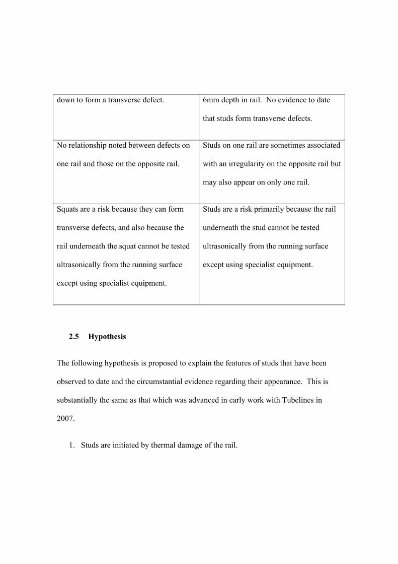
down to form a transverse defect. 6mm depth in rail. No evidence to date
that studs form transverse defects.
No relationship noted between defects on
one rail and those on the opposite rail.
Studs on one rail are sometimes associated
with an irregularity on the opposite rail but
may also appear on only one rail.
Squats are a risk because they can form
transverse defects, and also because the
rail underneath the squat cannot be tested
ultrasonically from the running surface
except using specialist equipment.
Studs are a risk primarily because the rail
underneath the stud cannot be tested
ultrasonically from the running surface
except using specialist equipment.
2.5 Hypothesis
The following hypothesis is proposed to explain the features of studs that have been
observed to date and the circumstantial evidence regarding their appearance. This is
substantially the same as that which was advanced in early work with Tubelines in
2007.
1. Studs are initiated by thermal damage of the rail.

2. Thermal damage results from limited wheelslip, possibly associated with
localised areas of poor adhesion. Where studs appear on one rail, there is
circumstantial evidence that this results from different friction conditions on the
two rails. These would cause one wheel to slip preferentially and the other to
slip as a result of the two wheels being interconnected. In such circumstances,
thermal damage would be greater on the rail with greater friction, so the stud
would initiate on this rail.
3. Studs are associated with vehicles having AC traction or thyristor-controlled DC
traction because wheelslip is better controlled than with conventional DC
traction. Severe wheelburns are a consequence of gross wheelslip, which may
be more common on older forms of DC traction because of more basic wheelslip
control. More modern traction systems commonly have higher limiting values
of “traction coefficient” i.e. the ratio of traction : normal load. This is
particularly the case with so-called “high traction” locomotives that are widely
used on the heavy haul systems examined by Marich and his colleagues [3,4].
4. Studs appear on open track and not in tunnels because wheel/rail friction is
lower in open track and conditions exist for wheelslip to occur. In tunnels,
limiting friction is commonly (but not always) sufficiently high to sustain high
traction ratios.

5. The mechanism by which studs propagate is unclear, but may be a low cycle
fatigue mechanism associated with contact stresses, of a similar form to that
which causes shells to propagate initially parallel to the rail surface [14,15].
3 Conclusions
A type of rail defect has been observed increasingly in the last 10-15 years that bears
superficial similarities to the so-called “squat”, which is a surface-initiated rolling
contact fatigue defect that was first identified in the 1970s. The more recent defect
which is christened here as a “stud”, appears to those who undertake ultrasonic testing
of rails to be sufficiently similar to the classical squat for them to classify it as such.
Although there is no evidence to date that studs break rails, whereas breaks commonly
develop from squats, the fact that there is a sub-surface crack makes the rail
“ultrasonically untestable” (at least by conventional means). The defect must therefore
be removed or an alternative treatment or inspection method developed. Studs can be
extremely common and concentrated within short sections of track: they appear to be
particularly prolific on the approach to signals and on the incline up from underground
sections of metro systems, where dozens may exist within a few hundred metres. Studs
also develop within about 10MGT, which is almost an order of magnitude more quickly
than squats.
Examinations have been made of studs in the field and a detailed metallurgical

examination has been made of studs removed from a metro line. From this work it is
clear that studs are not a conventional RCF phenomenon, and indeed that they can
develop (as in the sample considered here) in the absence of significant plastic
deformation of the rail surface. White-etching layer (WEL) is closely associated here
and in some previous work with studs, and it is proposed here that the white-etching
layer is a fundamental component of the mechanism of thermal damage as a result of
controlled wheelslip that initiates a stud. Different forms of damage, such as
irregularity of the running surface and patches of WEL, have been noted on pairs of
opposite (left and right) rails in the field and in the laboratory, which is consistent with
the proposed initiation mechanism by controlled wheelslip.
Studs appear to be associated with more modern traction control systems, in particular
AC traction, in which wheelslip is better controlled to permit operation at higher
traction ratios. It may correspondingly be the case that wheelburns are less common
with such traction packages.
Work is in hand to test the proposed hypothesis more fully and, if it is found to be
viable, to develop a way of obtaining the benefits of modern traction control systems at
less cost in rail (and possibly also wheel) damage.

4 Acknowledgements
The authors are grateful to Tubelines Ltd for supporting the initial work and the
metallurgical analysis contained in this paper and to Tubelines and Transport for
London for permission to publish the paper. They are also grateful to the reviewers for
their constructive suggestions on the initial paper, and to other railway systems and
suppliers whose support has made it possible to collate the material presented here.
Parts of this work were presented at the 8th
International Conference on Contact
Mechanics and Wear of Rail/Wheel Systems in Florence in September 2009.
5 References
1. Clayton, P. and Allery, M.B.P., Metallurgical aspects of surface damage problems in
rails, Canadian Metallurgical Quarterly, 1982, 21(1), 31-46
2. Kondo, K., Yoroizaka, K. and Sato, Y., Cause, increase, diagnosis, countermeasures and
elimination of Shinkansen shelling, 1996, Wear, 191, 199-203
3. Rail Defects Handbook, Some Rail Defects, their Characteristics, Causes and
Control, RC 2400, Issue A, Revision 0, March 2006, Australian Rail Track
Corporation Ltd.
http://extranet.artc.com.au/docs/engineering/tech_bulletins/manuals/section01/rc2400_ra
il_defects_handbook.pdf at 29 May 2011

4. Kerr M, Wilson A and Marich S, The epidemiology of squats and related rail defects,
Proceedings RTSA CORE Conference on Railway Engineering, Perth, Australia,
September 2008, 83-96
5. Li, Z., Zhao, X., Esveld, C., Dollevoet, R. and Molodova, M., An investigation into the
causes of squats – correlation analysis and numerical modelling, , Wear, 2008, 265,
1349-1355 (also Procs. of 7th Intnl Conf on Contact Mechanics and Wear of Rail/Wheel
Systems, Brisbane, 2006, 329-446)
6. Grassie, S.L., Squats and squat-type defects in rails: the understanding to date,
companion paper
7. Burstow, M., Kapoor, A., Fletcher, D.I. and Franklin, F., Crack development, chapter 4.4
in, Best practice in wheel/rail interface management for mixed traffic railways, Schmid,
F. et al (eds), University of Birmingham Press, Birmingham, UK, 1st edition, 2010, 4.19-
4.30
8. Li, Z., Squats on railway rails, chapter 13 in Wheel/rail interface handbook, Lewis, R.
and Olofsson, O. (eds), Woodhead Publishing Ltd, Oxford, 2009, 409-436
9. Grassie, S.L., Saxon, M.J. and Smith, J.D., Measurement of longitudinal rail
irregularities and criteria for acceptable grinding, Journal of Sound and Vibration, 1999,
227, 949-964

10. Grassie, S.L., Rail corrugation: characteristics, causes and treatments, Journal of Rail and
Rapid Transit, Procs of I mech E, 2009, 223F, 581-596
11. Ivanisenko, Y., MacLaren, I., Sauvage, X., Valiev, R.Z. and Fecht, H.-J., Shear-induced
! " # transformation in nanoscale Fe-C composite, Acta Materialia, 54 (6), 2006, 1659-
1669
12. Callister, W.D., ‘Phase Transformations in Metals’, Chapter 10 in Materials Science and
Engineering, John Wiley & Sons, 2006, ISBN 9780471736967
13. Newcomb, S.B. and Stobbs, W.M., A transmission electron microscopy study of the
white etching layer on a railhead, Materials Science and Engineering, 66, 1984, 195-204
14. Grassie, S.L. and Kalousek, J., Rolling contact fatigue of rails: characteristics, causes and
treatments, Procs of 6th Intnl Heavy Haul Railway Conference, Cape Town, 1997, 381-
404
15. Hellier, A.K., Corderoy, D.J.H. and McGirr, M.B., A study of sub-surface rail/wheel
contact stresses with application to modelling rail fatigue, in Contact mechanics and
wear of rail/wheel systems II, Gladwell G.M. et al (eds), University of Waterloo Press,
1986, 417-434

Figure captions
1 “Studs” from three railways (arrows on the rails in (a) and (b) point in direction
of traffic and towards gauge face; arrows superposed on photos point to the apex
of the “V” shaped crack)
2 Defect “map”, showing position of defects on the Central Line
3 Cross section of defect, showing depth of a few millimetres below rail surface
and length of about 30mm
4 Observations and measurements from opposite rails at defect locations
(classified as “squats” on left rail at 3.55m and on right rail at 7.4m)
5 Overview of rails at site A 430mm defect
6 Detail of defect on right rail
7 Irregularities on defective rail, opposite rail and a reference section of rail. The
reference data is vertically offset for clarity. (a) Defect location 430mm. (b)
Defect location 1450mm.
8 Detail of crack in defective rail, formed using multiple micrographs. (a)
Location 430mm. (b) Location 1450mm.

9 White etching layer on the rail running surface. (a) Location 430mm, left rail.
(b) Location 430mm, right rail. (c) Location 1450mm, left rail. (d) Location
1450mm, right rail. All sections are in the rail longitudinal direction, except (b)
which is from a transverse section.
10 Variation in surface hardness on defective rail and opposite rail (aligned) for
locations (a) 430mm and (b) 1450mm. Average of two readings at each position.

Figure 1
(a)
(b)

(c)

Figure 2

Figure 3

Figure 4

Figure 5

Figure 6

Figure 7
(a)
(b)


Figure 8
(a)
(b)

Figure 9
(a) (b)
(c) (d)

Figure 10
(a)
(b)
