study of a multi-phase hybrid heat exchanger …
TRANSCRIPT

AFRL-RQ-WP-TP-2014-0131
STUDY OF A MULTI-PHASE HYBRID HEAT EXCHANGER-REACTOR (HEX REACTOR): PART II – NUMERICAL PREDICTION OF THERMAL PERFORMANCE (POSTPRINT) Nicholas Niedbalski and Debjyoti Banerjee Texas A&M University Douglas Johnson University of Dayton Research Institute Soumya S. Patnaik Mechanical and Thermal Systems Branch Power and Control Division NOVEMBER 2013
Approved for public release; distribution unlimited.
See additional restrictions described on inside pages
STINFO COPY
AIR FORCE RESEARCH LABORATORY AEROSPACE SYSTEMS DIRECTORATE
WRIGHT-PATTERSON AIR FORCE BASE, OH 45433-7542 AIR FORCE MATERIEL COMMAND
UNITED STATES AIR FORCE

NOTICE AND SIGNATURE PAGE
Using Government drawings, specifications, or other data included in this document for any purpose other than Government procurement does not in any way obligate the U.S. Government. The fact that the Government formulated or supplied the drawings, specifications, or other data does not license the holder or any other person or corporation; or convey any rights or permission to manufacture, use, or sell any patented invention that may relate to them. This report was cleared for public release by the USAF 88th Air Base Wing (88 ABW) Public Affairs Office (PAO) and is available to the general public, including foreign nationals. Copies may be obtained from the Defense Technical Information Center (DTIC) (http://www.dtic.mil). AFRL-RQ-WP-TP-2014-0131 HAS BEEN REVIEWED AND IS APPROVED FOR PUBLICATION IN ACCORDANCE WITH ASSIGNED DISTRIBUTION STATEMENT. *//Signature// //Signature// TRAVIS E MICHALAK THOMAS L. REITZ, Technical Advisor Program Manager Mechanical and Thermal Systems Branch Mechanical and Thermal Systems Branch Power and Control Division Power and Control Division Aerospace Systems Directorate //Signature// JOHN G. NAIRUS, Chief Engineer Power and Control Division Aerospace Systems Directorate This report is published in the interest of scientific and technical information exchange, and its publication does not constitute the Government’s approval or disapproval of its ideas or findings. *Disseminated copies will show “//Signature//” stamped or typed above the signature blocks.

REPORT DOCUMENTATION PAGE Form Approved OMB No. 0704-0188
The public reporting burden for this collection of information is estimated to average 1 hour per response, including the time for reviewing instructions, searching existing data sources, searching existing data sources, gathering and maintaining the data needed, and completing and reviewing the collection of information. Send comments regarding this burden estimate or any other aspect of this collection of information, including suggestions for reducing this burden, to Department of Defense, Washington Headquarters Services, Directorate for Information Operations and Reports (0704-0188), 1215 Jefferson Davis Highway, Suite 1204, Arlington, VA 22202-4302. Respondents should be aware that notwithstanding any other provision of law, no person shall be subject to any penalty for failing to comply with a collection of information if it does not display a currently valid OMB control number. PLEASE DO NOT RETURN YOUR FORM TO THE ABOVE ADDRESS.
1. REPORT DATE (DD-MM-YY) 2. REPORT TYPE 3. DATES COVERED (From - To) November 2013 Journal Article Postprint 01 October 2011 – 28 May 2013
4. TITLE AND SUBTITLE STUDY OF A MULTI-PHASE HYBRID HEAT EXCHANGER-REACTOR (HEX REACTOR): PART II – NUMERICAL PREDICTION OF THERMAL PERFORMANCE (POSTPRINT)
5a. CONTRACT NUMBER In-house
5b. GRANT NUMBER
5c. PROGRAM ELEMENT NUMBER 62203F
6. AUTHOR(S)
Nicholas Niedbalski and Debjyoti Banerjee (Texas A&M University) Douglas Johnson (University of Dayton Research Institute) Soumya S. Patnaik (AFRL/RQQM)
5d. PROJECT NUMBER 3145
5e. TASK NUMBER N/A
5f. WORK UNIT NUMBER
Q0LA 7. PERFORMING ORGANIZATION NAME(S) AND ADDRESS(ES) 8. PERFORMING ORGANIZATION Texas A&M University Department of Mechanical Engineering 3123 TAMU College Station, TX 77843 ------------------------------------------------- University of Dayton Research Institute 300 College Park Dayton, OH 45469
Mechanical and Thermal Systems Branch (AFRL/RQQM) Power and Control Division Air Force Research Laboratory Aerospace Systems Directorate Wright-Patterson Air Force Base, OH 45433-7542 Air Force Materiel Command, United States Air Force
REPORT NUMBER AFRL-RQ-WP-TP-2014-0131
9. SPONSORING/MONITORING AGENCY NAME(S) AND ADDRESS(ES) 10. SPONSORING/MONITORING Air Force Research Laboratory Aerospace Systems Directorate Wright-Patterson Air Force Base, OH 45433-7542 Air Force Materiel Command United States Air Force
AGENCY ACRONYM(S) AFRL/RQQM
11. SPONSORING/MONITORING AGENCY REPORT NUMBER(S)
AFRL-RQ-WP-TP-2014-0131
12. DISTRIBUTION/AVAILABILITY STATEMENT Approved for public release; distribution unlimited.
13. SUPPLEMENTARY NOTES PA Case Number: 88ABW-2013-2498; Clearance Date: 28 May 2013. Report published in International Journal of Heat and Mass Transfer 70 (2014). The U.S. Government is joint author of the work and has the right to use, modify, reproduce, release, perform, display, or disclose the work.
14. ABSTRACT Numerical models were developed to assess the thermal performance of a HEX reactor with solid-to-gas reacting flow. Based on the experimental results obtained in part I of this study, numerical models were developed to predict the thermal performance of a plate heat exchanger-based HEX reactor involving multi-phase flow with chemical reactions. A reduced-order numerical model of a chevron plate heat exchanger was developed with thermal and momentum transfer analogies. Empirical correlations for momentum transfer and void fraction (validated in part I of this study) were implemented in the numerical model. The numerical model, coded in Maple 13™, was used to size a compact reactor with a thermal load rating of 2 kW for the desired operating temperature; the modeling framework developed can also be used to study different candidate gas-generating reacting species, working fluids, and PHE configurations.
15. SUBJECT TERMS ammonium carbamate, HEX Reactor, thermal management, plate heat exchanger, reacting flow, multi-phase flow
16. SECURITY CLASSIFICATION OF: 17. LIMITATION OF ABSTRACT:
SAR
18. NUMBER OF PAGES
16
19a. NAME OF RESPONSIBLE PERSON (Monitor) a. REPORT Unclassified
b. ABSTRACT Unclassified
c. THIS PAGE Unclassified
Travis E. Michalak 19b. TELEPHONE NUMBER (Include Area Code)
N/A Standard Form 298 (Rev. 8-98)
Prescribed by ANSI Std. Z39-18

International Journal of Heat and Mass Transfer 70 (2014) 1086–1094
Contents lists available at ScienceDirect
International Journal of Heat and Mass Transfer
journal homepage: www.elsevier .com/locate / i jhmt
Study of a multi-phase hybrid heat exchanger-reactor (HEX reactor):Part II – Numerical prediction of thermal performance
0017-9310/$ - see front matter � 2013 Elsevier Ltd. All rights reserved.http://dx.doi.org/10.1016/j.ijheatmasstransfer.2013.10.067
⇑ Corresponding author at: Air Force Research Laboratory, Aerospace SystemsDirectorate, Power and Controls Division, Mechanical and Thermal Systems Branch,A236, Building 18, 1950 5th St., Wright-Patterson AFB, OH 45433, United States.Tel.: +1 (425) 358 1295.
E-mail address: [email protected] (N. Niedbalski).
Approved for public release; distribution unlimited.
Nicholas Niedbalski a,b,⇑, Douglas Johnson c, Soumya S. Patnaik a, Debjyoti Banerjee b
a Air Force Research Laboratory, Aerospace Systems Directorate, Power and Controls Division, Mechanical and Thermal Systems Branch, 1950 5th St., Wright-Patterson AFB, OH45433, United Statesb Texas A&M University, Department of Mechanical Engineering, 3123 TAMU, College Station, TX 77843, United Statesc University of Dayton Research Institute, 300 College Park, Dayton, OH 45469, United States
a r t i c l e i n f o
Article history:Available online 16 November 2013
Keywords:Ammonium carbamateHEX reactorThermal managementPlate heat exchangerReacting flowMulti-phase flow
a b s t r a c t
Numerical models were developed to assess the thermal performance of a HEX reactor with solid-to-gasreacting flow. Based on the experimental results obtained in part I of this study, numerical models weredeveloped to predict the thermal performance of a plate heat exchanger-based HEX reactor involvingmulti-phase flow with chemical reactions. A reduced-order numerical model of a chevron plate heatexchanger was developed with thermal and momentum transfer analogies. Empirical correlations formomentum transfer and void fraction (validated in part I of this study) were implemented in the numer-ical model. The numerical model, coded in Maple 13™, was used to size a compact reactor with a thermalload rating of 2 kW for the desired operating temperature; the modeling framework developed can alsobe used to study different candidate gas-generating reacting species, working fluids, and PHEconfigurations.
� 2013 Elsevier Ltd. All rights reserved.
1. Introduction
Chevron PHEs are known to provide high heat transfer coeffi-cients with a high surface area-to-volume ratio [1], enabling highthermal power ratings without incurring significant footprint ex-penses. The corrugated plate geometry also produces swirling sec-ondary flows and early transition to turbulence at low Re, yieldingnear-ideal mixing behavior in addition to exceptional thermal per-formance: for instance, Santacesaria et al. [2] reported higheryields of biodiesel at relatively low Re, which they credited tostrong localized micromixing and turbulence. Edge et al. [3] useda model single-phase exothermic reaction to characterize bothheat transfer and reactant micromixing performance for a PHE-based HEX reactor. Their results showed reduced byproduct forma-tion indicative of high micromixing.
The results reported in the literature suggest tremendouspotential for the HEX reactor scheme introduced in a previousstudy [4], and discussed in part I of this study. Nevertheless, it isclear that there is a lack of both experimental and theoreticalunderstanding of solid-to-gas reacting flows in a chevron PHE.Consideration of such a unique HEX reactor will require extensive
exploration from an analysis and design standpoint. It is thereforeimportant to develop reliable and accurate models to predict boththe thermal performance and conversion efficiency of a given HEXreactor design, in effect providing an initial feasibility test for theHEX reactor’s role as a thermal management scheme. There ap-pears to be only a limited number of models developed for chevronPHE-based HEX reactors (such as that developed by Edge et al. [3]),none of which consider multi-phase flows. On the other hand,models developed for chevron PHEs that consider multi-phaseflows focus on refrigerant evaporation and/or condensation (e.g.,[5,6]), but without chemical reaction. To our knowledge, thereare no models proposed in the open literature that are applicableto solid-to-gas reacting flow in a chevron PHE. Hence, the focusof this paper is to develop a computer model for the coupled heat,momentum, mass transfer, and chemical kinetics of an endother-mic solid–gas reaction in a chevron PHE. The model predictionsfor thermal–hydraulic performance were used to demonstratethe utility of the solid–gas endothermic HEX reactor for thermalmanagement. Calculations were performed using the void fractionand two-phase multiplier correlations that were experimentallyvalidated in part I. Thermal performance estimates were obtainedusing a modified heat/momentum transfer analogy from the liter-ature that has been developed for PHEs.
The volumetric energy densities of thermochemical reactionsgenerally exceed that of thermophysical reactions. It has beenpreviously demonstrated [4] that the endothermic solid-to-gasdecomposition of ammonium carbamate (AC) holds significant
1

Nomenclature
A surface areaC mass concentrationD diameterDa Damköhler numberG constant in Eq. (3)L length_M000 dimensionless reaction rate
Nu Nusselt numberP pressurePp partial pressurePr Prandtl numberQlatent heat rejected to ammonium carbamateQload total heat rejectedR heat capacity ratioRe Reynolds numberT temperatureT⁄ normalized load temperatureT�ld load temperature at full conversionU superficial velocityV volumeW plate width (between gasket)X Lockhart–Martinelli parameter
Lowercasesa rate constant in Eq. (2)d ½ corrugation depthcp specific heat capacitye constant in Eq. (3)f Darcy friction factorg gravitational accelerationh convection coefficient1/heff overall thermal resistancei cell indexk thermal conductivitykplate thermal conductivity of plate_m000 volumetric reaction rate_m00total total mass flux
n channel index
q00 wall heat fluxtplate plate thicknessu velocity_w power rating
x mass qualityz dimensionless axial coordinatez⁄ axial coordinate
GreeksK corrugation pitchH dimensionless temperature in Figs. 9 and 10UAE area enlargement factorU2
TP two-phase multipliera void fractionb chevron angleh dimensionless temperaturee Qlatent/Qload
j rate constantg dimensionless concentrationq density
SubscriptsA accelerationF frictionG gravitySP single-phaseTP two-phasec corrugated sectione equivalenteq at equilibriumg gas phaseh hydraulicin value at inletld liquid phase, load sidels liquid phase, slurry sidep AC particlepp port-to-port
N. Niedbalski et al. / International Journal of Heat and Mass Transfer 70 (2014) 1086–1094 1087
potential as a high energy density thermochemical heat sink forthermal management. AC is a salt that is readily available in pow-der form as a cheap byproduct of urea synthesis [7]. AC undergoesa reversible solid–gas decomposition reaction, shown below:
NH2COONH4ðsÞ ! CO2ðgÞ þ 2NH3ðgÞ ð1Þ
Despite the low operating temperature (�70 �C) and high en-ergy density (2000 kJ/kg), the impediment to AC in a practical ther-mal management system is its low thermal conductivity (�0.4 W/m K) [7]. This presents a significant barrier to conducting thermalenergy in bulk AC salt. Schmidt [7] proposed forming reacting slur-ry by immersing small AC salt particles in a non-reactive heattransfer fluid (HTF) to overcome this impediment. Previous re-search [8,9] demonstrated successful use of PHEs with slurries con-taining thermophysical phase-change materials (PCM). However,due to the high enthalpy of decomposition, AC can enable higheroverall energy density to be achieved than with the thermophysi-cal PCM slurries considered in the aforementioned studies.
2. Mathematical analysis
Gasketed chevron PHEs are a stack of channels formed by thincorrugated heat transfer plates which are separated by gaskets.The corrugations are aligned in a repeating series of chevrons to
Approved for public release;
form an oblique, wavy surface. A discussion of the background ofPHEs is provided by Johnson et al. [4] and in part I of this study.The geometric characteristics of the PHE used in this study are de-picted in Fig. 1.
A schematic of the HEX reactor architecture considered in thisstudy is shown in Fig. 2. A hot stream fluid delivers heat to the coldstream fluid carrying suspended AC; the PHE has a single-pass,parallel, vertical upflow arrangement. The model developed in thisstudy considers the PHE to comprise of a stack of equivalent flatplates, forming a collection of N channels as illustrated in Fig. 2.Each channel is represented by a ‘submodel’ whose interactionwith other submodels in the system is defined by appropriateboundary conditions, as illustrated in Fig. 3. In the case consideredhere, channel submodels are permitted to interact by exchangingthermal energy. The heat transfer coefficient, friction factor, two-phase multiplier, and void fraction are estimated by employingempirical correlations obtained from the literature.
This approach is based on the idea of hierarchical modeling,which has been previously employed for the analysis of PHEperformance in industrial applications [10]. The treatment ofindividual channels as separate submodels (Fig. 3) also allows fornon-idealities seen in real heat exchangers, such as maldistributionof flow patterns, to be incorporated into the overall reactor model(Fig. 2).
distribution unlimited. 2

βLc
Distribu�on Zones
Gasket (Approx. loca�on)W
Lpp
Λ
2d
Fig. 1. (Left) Image of a representative chevron PHE heat transfer plate (Alpha Laval MF3) used in this study. (Right) Wavy corrugation profile observed in side view.
Slurry and GasOut + Q
Load Out - Q
Slurry In
Load In
Lpp
z*
Fig. 2. Schematic of reactor flow arrangement.
U(n)Tin(n)Cin(n)Pin(n)
U(n+1)Tin(n+1)
z*
tw
De
De
Lpp
Plate j
Plate j-1
Plate j+1
Cold (Slurry) SideChannel n
Hot (Load) SideChannel n+1
)( *1, zq nw −′′
)( *, zq nw′′
)( *1, zq nw +′′
Fig. 3. Interaction between channel submodels.
1088 N. Niedbalski et al. / International Journal of Heat and Mass Transfer 70 (2014) 1086–1094
2.1. Transport equations
The separated flow model [11] is used for developing the trans-port equations of energy, mass, and momentum for the liquid andgas phases in the multi-phase flow configuration, wherein the gasphase and liquid phase (heat transfer fluid and suspended solid)are considered segregated. The mutual interactions between gasand liquid phase are estimated using appropriate experimentalcorrelations (validated from the experiments conducted in part Iof this study).
Some of the assumptions used in the HEX reactor model arelisted as follows:
� Steady-state operation (using time averaged values).� The gas mixtures (reaction products) are insoluble in the liquid
phase.� No evaporation occurs in the liquid phase on the slurry side.� The flow is approximated as a pseudo two-phase flow (homoge-
neous flow model for the AC in the liquid) where the liquid‘‘solution’’ of AC (rather than a collection of discrete particles)is considered to undergo uniform volumetric heat generation(or heat sink) due to homogeneously distributed volumetricchemical reactions and mass concentration at a given axiallocation.
Approved for public releas
� Due to the small particle size, the contribution of the suspendedsolids on the momentum equation is negligible [12] (i.e., thesmall concentration of the tiny suspended particles does notcause appreciable change in the effective viscosity and rheolog-ical properties of the bulk liquid phase).� Reduced order models involving one-dimensional equivalent
flows are used; i.e., cross-sectional variation in the temperature,velocity, and void fraction profiles are replaced by area aver-aged quantities.o Primary flow variables are permitted to differ between the
liquid and gas phases (separated flow model).o Heat transfer to the gas phase is negligible when compared
to heat transferred to the liquid phase and the suspendedAC. This is a reasonable engineering approximation due tothe short residence times and the low thermal conductivityvalues of the gas phase compared to that of the liquid phase.
� The reaction occurs at the local bulk temperature due to homo-geneous mixing produced by bubble agitation and secondaryflows characteristic of PHEs.� Negligible conduction heat transfer in the axial direction.� Fluids are Newtonian and incompressible.
In accordance with the aforesaid assumptions, an integral mass,species, energy, and momentum balance on a 1-dimensional controlvolume yields the following governing equations:
e; distribution unlimited. 3

0
200
400
600
800
1000
1200
1400
300 320 340 360 380
P eq
(kPa
)
T (K)
Fig. 4. Dissociation pressure Peq as a function of temperature predicted by Eq. (3)compared with experimental results obtained in the literature. Red squares:Koutinas et al. [14]; green triangles: Bennet et al. [15]; purple X’s: Egan and Potts[16]; blue asterisks: Briggs and Migrdichian [17]. (For interpretation of thereferences to color in this figure legend, the reader is referred to the web versionof this article.)
N. Niedbalski et al. / International Journal of Heat and Mass Transfer 70 (2014) 1086–1094 1089
2.1.1. Continuity
uls;n ¼Uls;n
1� anð2Þ
ug;n ¼Uls;nðCin;n � CnÞ
qg;nanð3Þ
where u is the velocity (m/s), U is the superficial velocity (m/s), q isthe density (kg/m3), and C is the mass concentration of solid AC (kg/m3) per unit volume of liquid slurry.
2.1.2. Species
UlsdCn
dz�¼ � _m000n ð1� anÞ ð4Þ
where _m000 is the volumetric reaction rate (kg/m3 s) per unit volumeof liquid slurry.
2.1.3. Energy
Uls;ndTn
dz�¼ � DH
qlscp;ls_m000n ð1� anÞ þ
q00n þ q00n�1
Deqlscp;lsð5Þ
Uld;ndTn
dz�¼ q00n þ q00n�1
Deqldcp;ldð6Þ
where T is the temperature (K), q00 is the wall heat flux (W/m2), cp isthe specific heat capacity (J/kg K), and De is the equivalent diameter(m, twice the corrugation amplitude). The momentum equationsplits the total pressure gradient into frictional, hydrostatic, andacceleration components [11]:
2.1.4. Momentum
dPn
dz�¼ dPF;n
dz�þ dPG;n
dz�þ dPA;n
dz�ð7Þ
where,
dPA;n
dz�¼ uls;nqlsð1� anÞ
duls;n
dz�þ ug;nqg;nan
dug;n
dz�ð8Þ
dPG;n
dz�¼ g½ð1� anÞqls þ anqg;n� ð9Þ
dPF;n
dz�¼ðfqU2Þls;n
2DhU2
TP;n ð10Þ
where g is the gravitational acceleration (m/s2), Dh is the hydraulicdiameter (m). The subscript n is used to indicate that the respectivequantity may vary from channel to channel. Inlet temperatures,pressures, concentrations, and flow rates to each channel are pre-sumed known. Heat transfer between channel submodels n andn � 1 is assumed to occur by 1-D heat conduction, as is typical inheat exchanger analysis [1]:
q00n�1 ¼1hnþ tplate
kplateþ 1
hn�1
� ��1
ðTn�1 � TnÞ ¼ heff ;n�1ðTn�1 � TnÞ ð11Þ
where h is the local convection coefficient (W/m2 K), tplate is the heattransfer plate thickness (m), and kplate is the thermal conductivity ofthe plate (W/m K). The end plates are treated as insulated bound-aries, since they are much thicker than the plates, and PHEs are de-signed to minimize heat losses to the environment through the endplates and gaskets [1].
Approved for public release;
2.2. Incorporation of kinetic model
The current state of knowledge about the kinetics of AC decom-position is quite limited; the open literature offers few mathemat-ical models for the reaction rate. As a starting point, we selectedClaudel and Boulamri’s [13] net rate model for the decompositionor formation of AC, as provided below:
dPp
dt¼ aApjPp � Peqj2 ð12Þ
where Pp is the partial pressure (kPa) of the NH3 and CO2 evolvedduring the course of decomposition, a is the rate coefficient (kPa/m2 s), and Ap is the surface area of solid AC (m2). The equilibriumpressure, Peq, follows an Arrhenius-type dependence on tempera-ture [14]:
PeqðTÞ ¼ G exp � eT
� �ð13Þ
where G and e are constants equal to 1.9122 � 1010 kPa and6321.7 K, respectively, as obtained from Koutinas et al. [14]. Fig. 4shows a plot of Eq. (13) as a function of temperature, with valuesmeasured from various sources in the literature. According to Eq.(13), the minimum operating temperature (under standard atmo-spheric pressure) for the system is �60 �C. Schmidt [7] also mea-sured the decomposition pressure as a function of temperature forAC immersed in propylene glycol or ethylene glycol, and found nosignificant departure from the curve described by Eq. (13).
The red arrow in Fig. 4 represents the thermodynamic ‘‘drivingforce’’ behind the reaction, or ‘‘equilibrium drop,’’ as some authorshave used for solid-to-gas reversible reactions [18]. The red dottedline represents the equilibrium vapor pressure corresponding tothe local temperature of the solid AC, whereas the black dotted linerepresents the local partial pressure acting on the reactor contents.Schmidt confirmed that the decomposition rate could be acceler-ated appreciably by maintaining the AC far from its equilibriumcondition, maximizing the equilibrium drop. This driving force isaccounted for in Claudel and Boulamri’s model. Since the form ofEq. (12) is indicative of a physical mechanism [13], we postulatethat the same mechanism will exist even when immersed in a heattransfer fluid.
The rate equation discussed above is incorporated into the spe-cies conservation equation via the volumetric reaction term, _m000n .
distribution unlimited. 4

1090 N. Niedbalski et al. / International Journal of Heat and Mass Transfer 70 (2014) 1086–1094
Assuming that the dependence upon surface area and equilibriumdrop is the same as that which was proposed by Claudel andBoulamri [13], the decomposition rate of an individual particle is:
ddtðqpVpÞ ¼ �jApjPeq � Pj2 ð14Þ
where Vp is the particle volume (m3), qp is the particle density (kg/m3) (assumed to be uniform throughout the particle), and j is thespecific rate coefficient based on surface area, which will assuredlydiffer from the rate constant calculated in Claudel and Boulamri’sstudy. As an initial approximation, since the variation of NH3 andCO2 partial pressures in the HEX reactor has not yet been experi-mentally investigated, the partial pressure Pp in Eq. (14) is assumedto equal the local static pressure of the liquid, P. Peq is a function oftemperature; Schmidt’s [7] results for AC in propylene glycol andethylene glycol match well with the Peq(T) curves obtained in liter-ature for dry AC [14], as described by Eq. (13).
It follows that the mass concentration of solid AC per unit volumeof liquid heat transfer fluid is C ¼ n000qpVp. On a volumetric basis, therate of solid mass consumption by decomposition may then be writ-ten, assuming that the particles are approximately spherical,
_m000 ¼ �xjC2=3jPeq � Pj2 ð15Þ
where x ¼ ð4pn000Þ1=3ð3=qpÞ2=3. This result can be inserted directly
into the cross-sectional average values governing Eqs. (4) and (5),assuming that n000 is constant. In order for such an assumption tohold, the following conditions must be satisfied:
� The particles are evenly distributed, and no agglomeration orbreak-up into smaller particles occur.� Particles do not accumulate within the reactor, nor are they
completely consumed by the reaction.� Particles at a given location within the channel are subject to
the same local pressure and temperature conditions.
In effect, these assumptions yield a shrinking core-type modelwherein only the size of the particles change as the reaction pro-gresses, with the reaction rate tending toward zero as the surfacearea available for reaction also tends toward zero.
To elucidate the important parameters influencing the solutionof the system, a non-dimensional analysis is performed. Introduc-ing the following dimensionless variables and assuming no maldis-tribution is present:
hn ¼Tn
DHCinqlscp;ls
� � ð16aÞ
gn ¼Cn
Cinð16bÞ
z ¼ z�
Lppð16cÞ
Da ¼ xjLpp
C1=3in Uls
jPeqðTld;inÞ � Patmj2 ð16dÞ
un ¼Lpp
De
Nun
RePrð16eÞ
R ¼ ðUqcpÞlsðUqcpÞld
ð16fÞ
_M000n ¼
g2=3n
PeqðTnÞ�Pn
PeqðTld;inÞ�Patm
h i2Peq > P
0 Peq � P
8<: ð16gÞ
Approved for public releas
The energy equation for the slurry side and load side, respectively,become:
dhn
dz¼ �Da _M000
n ð1� anÞ þunðhnþ1 � hnÞ þun�1ðhn�1 � hnÞ ð17Þ
dhn
dz¼ Rn½unðhnþ1 � hnÞ þunþ1ðhn�1 � hnÞ� ð18Þ
The species conservation equation becomes:
dgn
dz¼ �Da _M000
n ð1� anÞ ð19Þ
There are three dimensionless groups that arise: a Damköhler num-ber (Da), u, and heat capacity rate ratio (R). The Damköhler numberis a ratio of the timescale of the chemical reaction to the timescalefor mass transfer by advection. The group u, which is a function ofaxial position, is a dimensionless heat transfer coefficient thatrelates the magnitude of heat transfer by wall heat flux to heattransfer by advection; the Reynolds number and Prandtl numberare evaluated according to the physical properties and superficialvelocity of the slurry, and overall thermal resistance is used in placeof the convection coefficient in the Nusselt number.
2.3. Correlation selection
There are no correlations available in the literature developedspecifically for a reacting multi-phase flow in a chevron PHE. Thecriteria for selecting empirical correlations to explore the thermo-hydraulic performance should adhere to the following guidelines:
1. Conservative estimates are provided for reactor design.2. The correlations are applicable to a wide range of geometric
parameters for PHEs.
Many heat exchanger correlations are derived from heat andmomentum transfer data (i.e., f and Nu) averaged over the entirechannel length. However, the quantities to which the said data iscorrelated will vary with axial position, mostly due to changes inthe void fraction and mass quality of the flow. To account for thesevariations, it is assumed that these correlations may be appliedat the prevailing conditions at any axial location z, and inte-grated over the channel length – in essence, a quasi-equilibriummodel.
In this study, a semi-empirical model due to Martin [19] was se-lected for the single-phase friction factor, since it correlates datafor a range of chevron angles fairly well. Martin’s model is basedon observations gathered from earlier flow visualization studiesof the flow patterns inside PHEs [20,21], which showed that twotypes of flows exist simultaneously: crossing substreams that fol-low the corrugations, and sinusoidal wavy flow between the upperand lower plate corrugations as the fluid travels down the mainflow direction. Martin’s model is expressed as [19]:
1ffiffiffif
p ¼ cos bffiffiffiffiffiffiffiffiffiffiffiffiffiffiffiffiffiffiffiffiffiffiffiffiffiffiffiffiffiffiffiffiffiffiffiffiffiffiffiffiffiffiffiffiffiffiffiffiffiffiffiffiffiffiffiffiffiffiffiffiffiffiffiffiffiffiffiffiffi0:18 tan bþ 0:36 sin bþ f0 cos b
p þ 1� cos bffiffiffiffiffiffiffiffiffiffiffiffi3:8f 1
p ð20Þ
where,
f0 ¼64
RehReh < 2000
ð1:8 lnðRehÞ � 1:5Þ�2 Reh 2000
(ð21Þ
f1 ¼597Rehþ 3:85 Reh < 2000
39Re0:289
hReh 2000
(ð22Þ
where Reh is the Reynolds number based on the hydraulic diameter,defined as Dh ¼ 4b=UAE, with UAE being the area enlargement factor
e; distribution unlimited. 5

N. Niedbalski et al. / International Journal of Heat and Mass Transfer 70 (2014) 1086–1094 1091
given by the ratio of the actual surface area to the projected surfacearea of the corrugated chevron plate.
For two-phase flow, no reports exist on models or correlationsspecific to the reacting multi-phase flow configurations encoun-tered in this study. The most reasonable example in the literatureakin to this situation is that of air–water vertical upward flow,which a limited number of investigators have considered [22–27]. In the reacting slurry, the liquid phase and the gas byproductsdo not undergo additional phase changes, and changes in the flowquality only occur through chemical reaction rather than evapora-tion or condensation. One may imagine an equivalent air–waterflow in which gas is continuously introduced along the length ofthe channel; the implicit assumption in this analogy is that thehydrodynamics of air–water flow is similar to that of the gas evolv-ing reacting flow considered in this study.
Tribbe and Müller-Steinhagen [23,24] studied air–water two-phase vertical upflow in different commercial chevron PHEs havingdifferent corrugation depths and chevron angles. These authorsfound that their frictional pressure drop data, using the appropri-ate single-phase friction factor, could be well correlated by therelation [24]:
UTP ¼ 1:423� 0:0724 ln X þ 1:031=X ð23Þ
where X is the Lockhart–Martinelli parameter, defined as:
X ¼
ffiffiffiffiffiffiffiffiffiffiffiffiffiffiffiffiffiffiffiffiffiffiffiffiffiffiffiffiffiffiffiffiffiffiffiffiffiffiffiffidPdz
� �F;l
,dPdz
� �F;g
vuut ð24Þ
Tribbe and Müller-Steinhagen [24] claim their correlation to bevalid within 0.06 < X < 10. From the experiments conducted in partI of this study, the frictional pressure drop could be adequatelydescribed by this correlation when a correction factor of 3.0 wasapplied. Since the reaction rates of the sodium bicarbonate/aceticacid system are much greater than the decomposition of AC (sincethe former is mixing-limited), and in the interest of obtaining con-servative estimates, the model presented here does not apply thiscorrection factor to Eq. (23). Likewise, following the recommenda-tion of Kreissig and Müller-Steinhagen [22], the void fraction wasestimated using Rouhani’s correlation [28]:
an ¼xn
qg;n½1þ 0:12ð1� xnÞ�ðxn=qg;n þ ð1� xnÞ=qlsÞn
þ1:18=ð _m00total;nq0:5ls Þ½grðqls � qg;nÞ�
0:25o�1
ð25Þ
where the total mass flux and quality, respectively, are expressedas:
_m00total ¼ Uls;n½qls þ Cin;nð1� gnÞ� ð26Þ
xn ¼ ð1� gnÞðqls=Cin;n þ 1� gnÞ�1 ð27Þ
As was shown in part I, even with a crude estimate of the reactionrate, the forgoing equations could be applied using local values for gand qg to obtain reasonable (for two-phase flow, at least) estimatesof the total pressure drop.
The Nusselt number for two-phase flow, lacking any correla-tions specifically for heat transfer in air–water flow in chevron-PHEs, requires recourse to heat/momentum transfer analogies. Inparticular, Martin [19], Schlünder [29], and Abu-Khader [30] havefound that a generalized form of the classical Lévêque solutioncould correlate heat transfer data obtained from chevron PHEs sur-prisingly well. Martin modified the original generalized Lévêqueequation to fit experimental data for turbulent flow in industrialPHEs from several sources to obtain the following expression:
Nuh ¼ 0:122Pr1=3ðl=lwÞ1=6½f Re2 sinð2bÞ�0:374 ð28Þ
Approved for public release;
Martin obtained the term sin (2b) by taking Dh/L to be the dis-tance between two crossing corrugations. One may, plausibly, ex-tend Martin’s adaptation of the generalized Lévêque solution tothe case of two-phase flow by recognizing the agitation and mixingcaused by the interaction between gas bubbles and a surroundingfluid is similar to that of turbulence [31]. The Lévêque solution isan asymptotic solution based on approximating the velocity profilein the vicinity of a solid wall as linear, a more involved discussionof which may be found in Ref. [32]. Since the only change herefrom Lévêque’s original analysis is the inclusion of the two-phasemultiplier, one finds that Nuh ¼ NuhðU2
TPf Re2hÞ. Without sufficient
data to re-adjust the constants in Martin’s adaptation of the gener-alized Lévêque equation, we opted simply to insert the two-phasemultiplier into the bracketed term in Eq. (28):
Nuh ¼ 0:122 Pr1=3ðlls=lls;wÞ1=6 flsU
2TPRe2 sinð2bÞ
h i0:374ð29Þ
The exponent 0.374 and leading multiplier 0.122 are expected to re-quire adjustment to better match multi-phase reacting flow in achevron PHE. As long as the thermal boundary layer remains thin,as it would in turbulent flow or highly agitated two-phase flow,one can expect the Lévêque correlation to be an appropriate basisfor two-phase flow correlations in chevron PHEs. Eq. (29) impliesthat the added presence of a gas phase, which will yield U2
TP > 1,actually enhances heat transfer. Such enhancement was observedby Vlasogiannis et al. [27] in their study of heat transfer with air–water flow in a vertical chevron PHE. Based on their experiments,Vlasogiannis et al. reported enhancements in the values of heattransfer coefficient in all cases where air was injected with waterat the inlet.
2.4. Numerical procedure
The transport equations were solved using the finite-volumemethod, with each channel being partitioned into equally sizedcells. Eqs. (7) and (17)–(19) are integrated over each cell, whereupon Gauss’ divergence theorem is used to change the volumeintegrals of the convective and diffusive terms into fluxes at thecell face. 1st order upwind differencing is used for the convectivefluxes, and 2nd order central differencing is used for the diffusivefluxes. A grid resolution of 100 cells per channel was found to besufficient to establish grid independence.
Addressing the nonlinear source terms in the species andenergy equations require an iterative approach. The energy andspecies conservation equations are linearized about an initialguess, and decoupled to form two separate linear systems, whichare subsequently solved using conventional sparse matrix tech-niques. The pressure field is updated at the end of each iteration.The solver code was written in Maple 13™, and the matrix inver-sion was performed using the built in LinearSolve function. Forthe simulations presented in this paper, convergence typicallyrequires 50 iterations and 3 min of wall-clock time for execution.
3. Results and discussion
The numerical model described above was used to design andevaluate the performance of a ‘‘prototype’’ HEX reactor. The reactorconsists of 7 channels, 3 of which carry the slurry, and 4 of whichcarry the thermal load. This layout is shown in Fig. 3. The geomet-ric parameters, based off the Alfa Laval M3 PHE used in part I of thisstudy, are shown in Table 1. The intent of this exercise is to firstdetermine the dominant parameter (or parameters) governingreactor performance, and then to determine if the operating condi-tions required to achieve full conversion near atmospheric pres-sure conditions are indeed realistic.
distribution unlimited. 6
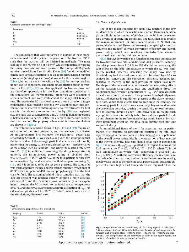
Table 1Geometric parameters for ‘‘prototype’’ PHE.
Parameter Value
L 0.48 mDe 0.00468 mW 0.10 mUAE 1.1b 30�
0.5
0.6
0.7
0.8
0.9
1
vers
ion
1092 N. Niedbalski et al. / International Journal of Heat and Mass Transfer 70 (2014) 1086–1094
The simulations that were performed in pursuit of these objec-tives assumed the slurry inlet temperature to be fixed at 335 K,such that the reaction will be initiated immediately. The massloading of the AC was held at 8 kg/m3 while systematically varyingthe slurry flow rate and inlet pressure. The slurry-side Reynoldsnumber ranged from 5 to 16; Abu Kader [30] found the modifiedgeneralized Lévêque equation to be an appropriate Nusselt numbercorrelation (in single-phase flow) at low Re for the chevron angle inTable 1, but no data exists to validate Eq. (29) for multi-phase flowunder low Re conditions. The single-phase friction factor correla-tions in Eqs. (20)–(22) are also applicable to laminar flow, andare therefore appropriate for the flow conditions considered inthe simulations. All thermophysical properties were assumed toremain constant, and were evaluated at the slurry inlet tempera-ture. This particular AC mass loading was chosen based on a targetendothermic heat rejection rate of 2 kW, assuming near total con-version. In the interest of obtaining conservative estimates for heattransfer, the viscosity correction term in Eq. (29) was neglected(i.e., the ratio was assumed to be unity). The load fluid temperatureis held constant to better isolate the effects of slurry-side convec-tion and reaction. The property values used for these simulationsare shown in Table 2.
The volumetric reaction terms in Eqs. (17) and (19) require anestimation of the rate constant, j, and the average particle size.As an approximate first estimate, the peak initial power datareported by Schmidt [7] was used, along with the assumption thatthe initial value of the average particle diameter was �1 mm. Byperforming the energy balance on a closed-system – representativeof the reactor used by Schmidt – and using the reaction rate termfrom Eq. (15) in addition to assuming the slurry temperature isuniform, the instantaneous power rating is obtained from_w ¼ DHAtotaljðP � PeqÞ2, where Atotal is the total particle surface area
in the reaction. Peq is calculated at the fluid temperature using Eq.(15), and P is assumed to be the set point pressure. The value of _wwas estimated from the peak power ratings reported by Schmidt at60 �C with a set point of 400 torr and propylene glycol as the heattransfer fluid. The reasoning behind this assumption was that the400 torr setpoint was reached quickly, offering a more accurateestimate of P; and the maximum power occurs early in the exper-iment, meaning the AC is closest to the initial reactor temperatureof 60 �C and thereby allowing more accurate estimation of Peq. Thiscalculation yields j = 2.4 � 10�10 m�2 kPa�2, which was used inthe simulations, discussed next.
Table 2Thermophysical properties used in simulations.
Property Value Units Source
kplate 13.4 W/m K [33]kls 0.196 W/m K [33]cp,ls 2700 J/kg K [34]lls 8.4 mPa s [35]lg 0.012 mPa s [33]qls 1036 kg/m3 [35]qp 780 kg/m3 [6]DH 2000 kJ/kg [6]
Approved for public releas
3.1. Numerical predictions
One of the major concerns for open flow reactors is the lowresidence time in which the reaction must occur. This considerationplaces a limit on the amount of AC that can be fed into the reactorfor a given set of operating conditions. The task, then, is to predictthe maximum amount (or mass concentration) of AC that canpotentially be reacted. There are three major competing factors thatinfluence the tradeoff between conversion efficiency and overallpower rating, which are: residence time/advection, channel-to-channel heat transfer, and reaction rate.
Fig. 5 displays conversion as a function of load side temperaturefor two different flow rates and different inlet pressures. Reducingthe inlet pressure from 110 kPa to 102 kPa did not have a signifi-cant effect on the load temperature at which the AC was com-pletely reacted, whereas increasing the slurry flow rate bythreefold required the load temperature to be raised by �10 K toachieve full conversion. The conversion efficiency becomes lesssensitive to changes in the inlet pressure at higher flow rates.The shape of the conversion curves reveals two competing effectson the reaction rate; surface area, and equilibrium drop. Theequilibrium drop, which is proportional to ðPeq � PÞ2 increases withaxial distance due to decrease in local pressure from hydrodynamiclosses, and increase in equilibrium pressure as the slurry tempera-ture rises. While these effects tend to accelerate the reaction, thedecreasing particle surface area eventually begins to dominatethe conversion behavior, causing the sensitivity to load tempera-ture to severely diminish after �90% conversion. In reality, suchasymptotic behavior is unlikely to be observed since particle breakup and changes in the surface morphology would have an increas-ingly prominent effect on the total solid surface area per unitvolume of slurry.
As an additional figure of merit for assessing reactor perfor-mance, it is insightful to consider the fraction of the total heatrejected (Qload) in the form of latent heat (Qlatent) as a supplementto the overall power rating. Ideally, the proportion of heat rejectedto the thermo-chemical heat sink should be as high as possible. InFig. 6, the ratio e = Qlatent/Qload is plotted with respect to normalizedload temperature, T� ¼ ðTld � 335 KÞ=ðT�ld � 335 KÞ, where T�ld is theload temperature at which ‘‘full’’ conversion is attained (i.e.,1 � g P 0.95). As with the conversion efficiency, the inlet pressurehas little effect on e as compared to the residence time. Increasingthe flow rate tends to increase the total power rating, but at the ex-pense of e since higher load temperatures are required. Thus, the
0
0.1
0.2
0.3
0.4
335 340 345 350 355
Con
Tld (K)
Fig. 5. Comparison of conversion efficiency (h) for slurry superficial velocities of0.01 m/s (dashed line) and 0.03 m/s (solid line) as a function of load temperature fordifferent inlet pressures: black – 102 kPa, green – 105 kPa, red – 108 kPa, and blue –110 kPa. (For interpretation of the references to color in this figure legend, thereader is referred to the web version of this article.)
e; distribution unlimited. 7
0
0.2
0.4
0.6
0.8
1
1.2
0 0.2 0.4 0.6 0.8 1
Qla
tent
/Qlo
ad
(Tload - Tslurry) / (Tload* - Tslurry)
Fig. 6. Fraction of total heat rejected in the form of latent heat as a function ofnormalized load temperature for different inlet pressures: black – 102 kPa, green –105 kPa, red – 108 kPa, and blue – 110 kPa. (For interpretation of the references tocolor in this figure legend, the reader is referred to the web version of this article.)
-0.4
-0.2
0
0.2
0.4
0.6
0.8
1
0 0.2 0.4 0.6 0.8 1
Θ,η
z
Fig. 7. Dimensionless axial temperature and concentration profiles for differentload temperatures (black – 336 K, green – 339 K, red – 342 K) with Uls = 0.01 m/s,Cin = 8 kg/m3, and Pin = 110 kPa. (For interpretation of the references to color in thisfigure legend, the reader is referred to the web version of this article.)
-0.4
-0.2
0
0.2
0.4
0.6
0.8
1
0 0.2 0.4 0.6 0.8 1
Θ,η
z
Fig. 8. Dimensionless axial temperature and concentration profiles for differentload temperatures (black – 336 K, green – 339 K, red – 342 K) with Uls = 0.01 m/s,Cin = 8 kg/m3, and Pin = 102 kPa. (For interpretation of the references to color in thisfigure legend, the reader is referred to the web version of this article.)
N. Niedbalski et al. / International Journal of Heat and Mass Transfer 70 (2014) 1086–1094 1093
increase in Nu accompanying lower residence times is outweighedby the higher heat capacity rate.
For operating conditions close to atmospheric pressure condi-tions, the pressure losses are insufficient to supply the equilibriumpressure drop needed to bridge the gulf between the advection andreaction timescales, as evidenced by the greater load temperaturesrequired at higher flow rates. It may be inferred from this fact thatthe global reaction rate is relatively insensitive to the axial variationof pressure (at least at the flow rates considered in this study), andis more sensitive to the axial variation in the slurry temperature.
From the standpoint of conversion efficiency and heat transfer, theresidence time is the dominant parameter for operation close toatmospheric pressure conditions. Increasing the residence time per-mits a greater portion of the total heat load to be rejected to the AC,but the overall power rating is diminished. Additional plates maybe added to the reactor to adjust the residence time to the appropriatelevel if one desires to react a greater quantity of AC by increasing theslurry flow rate. If the objective is to maximize the proportion of thethermal load rejected to the AC for a fixed PHE design, the residencetimes will need to be maximized to the greatest extent possible.
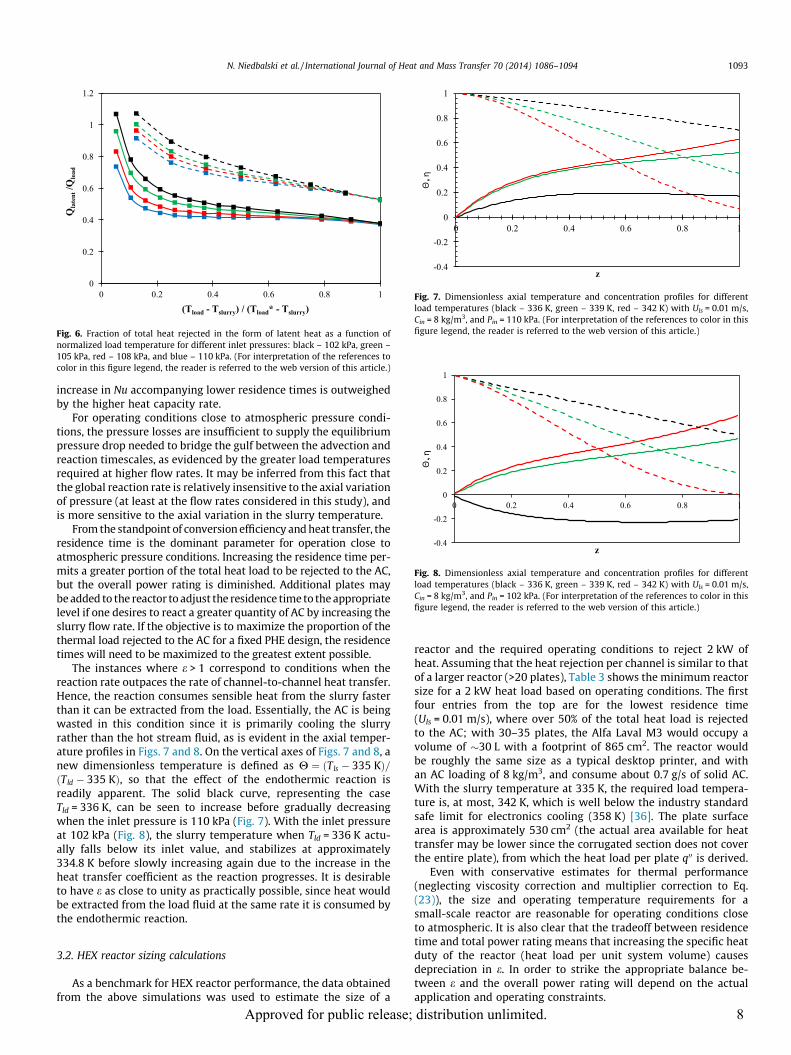
The instances where e > 1 correspond to conditions when thereaction rate outpaces the rate of channel-to-channel heat transfer.Hence, the reaction consumes sensible heat from the slurry fasterthan it can be extracted from the load. Essentially, the AC is beingwasted in this condition since it is primarily cooling the slurryrather than the hot stream fluid, as is evident in the axial temper-ature profiles in Figs. 7 and 8. On the vertical axes of Figs. 7 and 8, anew dimensionless temperature is defined as H ¼ ðTls � 335 KÞ=ðTld � 335 KÞ, so that the effect of the endothermic reaction isreadily apparent. The solid black curve, representing the caseTld = 336 K, can be seen to increase before gradually decreasingwhen the inlet pressure is 110 kPa (Fig. 7). With the inlet pressureat 102 kPa (Fig. 8), the slurry temperature when Tld = 336 K actu-ally falls below its inlet value, and stabilizes at approximately334.8 K before slowly increasing again due to the increase in theheat transfer coefficient as the reaction progresses. It is desirableto have e as close to unity as practically possible, since heat wouldbe extracted from the load fluid at the same rate it is consumed bythe endothermic reaction.
3.2. HEX reactor sizing calculations
As a benchmark for HEX reactor performance, the data obtainedfrom the above simulations was used to estimate the size of a
Approved for public release;
reactor and the required operating conditions to reject 2 kW ofheat. Assuming that the heat rejection per channel is similar to thatof a larger reactor (>20 plates), Table 3 shows the minimum reactorsize for a 2 kW heat load based on operating conditions. The firstfour entries from the top are for the lowest residence time(Uls = 0.01 m/s), where over 50% of the total heat load is rejectedto the AC; with 30–35 plates, the Alfa Laval M3 would occupy avolume of �30 L with a footprint of 865 cm2. The reactor wouldbe roughly the same size as a typical desktop printer, and withan AC loading of 8 kg/m3, and consume about 0.7 g/s of solid AC.With the slurry temperature at 335 K, the required load tempera-ture is, at most, 342 K, which is well below the industry standardsafe limit for electronics cooling (358 K) [36]. The plate surfacearea is approximately 530 cm2 (the actual area available for heattransfer may be lower since the corrugated section does not coverthe entire plate), from which the heat load per plate q00 is derived.
Even with conservative estimates for thermal performance(neglecting viscosity correction and multiplier correction to Eq.(23)), the size and operating temperature requirements for asmall-scale reactor are reasonable for operating conditions closeto atmospheric. It is also clear that the tradeoff between residencetime and total power rating means that increasing the specific heatduty of the reactor (heat load per unit system volume) causesdepreciation in e. In order to strike the appropriate balance be-tween e and the overall power rating will depend on the actualapplication and operating constraints.
distribution unlimited. 8

Table 3Reactor size (minimum number of plates) required to reject 2 kW of waste heat; DT = Tld � 335 K is the load–slurry temperature difference at the inlet.
Slurry flow rate (L/s) Qlatent (W) Qtotal (W) Qlatent /Qtotal DT (K) Pin (kPa) Min. plates q00 (W/cm2)
0.078 1114 2017 0.55 7.4 110 30 0.120.083 1185 2076 0.57 6.9 108 32 0.110.083 1185 2029 0.58 6.9 106 32 0.110.09 1293 2040 0.63 5.8 102 15 0.10.049 754 2015 0.37 19 110 6 0.580.056 862 2275 0.38 18.7 108 7 0.560.056 862 2228 0.39 18.1 105 7 0.550.056 862 2168 0.4 17.5 102 7 0.54
1094 N. Niedbalski et al. / International Journal of Heat and Mass Transfer 70 (2014) 1086–1094
4. Conclusions
In order to provide a useful engineering analysis tool to predictHEX reactor performance, we have developed a reduced-ordersemi-empirical model since the analysis of multi-phase flows isstill a heavily empirical practice [11]. The selection of empiricalcorrelations for the void fraction and two-phase multiplier wasguided by experimental data obtained in part I. As an initial feasi-bility study, a reduced-order reactor model was developed toascertain the critical parameters governing the performance. Themodel was based on conventional correlations for plate heatexchangers. The numerical results show that the conversion effi-ciency and the proportion of the total heat transferred consumedby the chemical reaction are more strongly influenced by the res-idence time than the operating pressure. Furthermore, the de-signed reactor meets the constraints for size and operatingtemperatures while achieving the required thermal load. A thermalload of 2 kW is designed to be handled by a PHE with a footprint ofonly 30 L in volume with operating conditions close to atmosphericpressure.
Disclosure statement
To our knowledge, there are no conflicts of interest between theauthors or their respective institutions with the International Jour-nal of Heat and Mass Transfer.
References
[1] E.C. Subbarao, R.A. Mashelkar, Heat Transfer Equip. Des. (1988) 227–254.[2] E. Santacesaria, M. Di Serio, R. Tesser, L. Casale, D. Verde, R. Turco, A. Bertola,
Use of a corrugated plates heat exchanger reactor for obtaining biodiesel withvery high productivity, Energy Fuels 23 (2009) 5206–5212.
[3] A.M. Edge, I. Pearce, C.H. Phillips, Compact heat exchangers as chemicalreactors for process intensification (PI), Proc. Intens. (1997) 175–189.
[4] D. Johnson, S. Patnaik, J. Ervin, An integrated chemical reactor-heat exchangerbased on ammonium carbamate, in: Proceedings of the SAE 2012 PowerSystems Conference, SAE International, Phoenix, 2012.
[5] J.R. García-Cascales, F. Vera-García, J. Gonzálvez-Maciá, J.M. Corberán-Salvado,M.W. Johnson, G.T. Kohler, Compact heat exchangers modeling: condensation,Int. J. Refrig. 33 (2010) 135–147.
[6] H. Qiao, V. Aute, H. Lee, K. Saleh, R. Radermacher, A new model for plate heatexchangers with generalized flow configurations and phase change, Int. J.Refrig. 36 (2013) 622–632.
[7] J.E. Schmidt, The use of ammonium carbamate as a high specific thermalenergy density material for thermal management of low grade heat (MSthesis), University of Dayton, Dayton, OH, 2011.
[8] J. Bellas, I. Chaer, S.A. Tassou, Heat transfer and pressure drop of ice slurries inplate heat exchangers, Appl. Therm. Eng. 22 (2002) 721–732.
[9] Z.W. Ma, P. Zhang, Pressure drop and heat transfer characteristics of clathratehydrate slurry in a plate heat exchanger, Int. J. Refrig. 34 (2011) 796–806.
[10] M.C. Georgiadis, S. Macchietto, Dynamic modeling and simulation of plate heatexchangers under milk fouling, Chem. Eng. Sci. 55 (2000) 1605–1619.
[11] V.P. Carey, Liquid–Vapor Phase-Change Phenomena: An Introduction to theThermophysics of Vaporization and Condensation Processes in Heat TransferEquipment, 1992, Taylor and Francis; Hebron.
Approved for public releas
[12] N.P. Cheremisinoff, R. Gupta, Handbook of Fluids in Motion, 1983, pp. 895–927, Ann Arbor Science Publishers; Ann Arbor.
[13] B. Claudel, L. Boulamri, A new model of gas–solid kinetics: the case ofammonium carbamate formation and decomposition, Thermochim. Acta 126(1988) 129–148.
[14] A.A. Koutinas, P. Yianoulis, A. Lycourghiotis, Industrial scale modelling of thethermochemical energy storage system based on CO2 2NH3 NH2COONH4
equilibrium, Energy Convers. Manage. 23 (1983) 55–63.[15] R.N. Bennet, P.D. Ritchie, D. Roxburgh, J. Thomson, The system ammonia
carbon dioxide ammonium carbamate. Part I. – the equilibrium ofthermal dissociation of ammonium carbamate, Trans. Faraday Soc. 49 (1953)925–929.
[16] E.P.J. Egan, J.E.J. Potts, G.D. Potts, Dissociation pressure of ammoniumcarbamate, Ind. Eng. Chem. 38 (1946) 454–456.
[17] T.R. Briggs, V. Migrdichian, The ammonium carbomate equilibrium, J. Phys.Chem. 28 (1924) 1121–1135.
[18] H. Lu, N. Mazet, B. Spinner, Modeling of gas-solid reaction – coupling of heatand mass transfer with chemical reaction, Chem. Eng. Sci. 51 (1996) 3829–3845.
[19] H. Martin, A theoretical approach to predict the performance of chevron-typeplate heat exchangers, Chem. Eng. Process. Process Intensif. 35 (1996) 301–310.
[20] W.W. Focke, J. Zachariades, The effect of the corrugation inclination angle onthe thermohydraulic performance of plate heat exchangers, Int. J. Heat MassTransfer 28 (1985) 1469–1479.
[21] W.W. Focke, P.G. Knibbe, Flow visualization in parallel-plate ducts withcorrugated walls, J. Fluid Mech. 165 (1986) 73–77.
[22] G. Kreissig, H.M. Müller-Steinhagen, Frictional pressure drop for gas/liquidtwo-phase flow in plate heat exchangers, Heat Transfer Eng. 13 (1992) 42–52.
[23] C. Tribbe, H.M. Müller-Steinhagen, Gas/liquid flow in plate-and-frame heatexchangers – part I: pressure drop measurements, Heat Transfer Eng. 22(2001) 5–11.
[24] C. Tribbe, H.M. Müller-Steinhagen, Gas/liquid flow in plate-and-frame heatexchangers – part II: two-phase multiplier and flow pattern analysis, HeatTransfer Eng. 22 (2001) 12–21.
[25] Y. Shiomi, S. Nakanishi, T. Uehara, Characteristics of two-phase flow in achannel formed by chevron type plates, Exp. Therm. Fluid Sci. 28 (2004) 231–235.
[26] K. Nilpueng, S. Wongwises, Two-phase gas–liquid flow characteristics inside aplate heat exchanger, Exp. Therm. Fluid Sci. 34 (2010) 1217–1229.
[27] P. Vlasogiannis, G. Karagiannis, P. Argyropoulos, V. Bontozoglou, Air–watertwo-phase flow and heat transfer in a plate heat exchanger, Int. J. MultiphaseFlow 28 (2002) 757–772.
[28] S.Z. Rouhani, E. Axelsson, Calculation of void volume fraction in the subcooledand quality boiling regions, Int. J. Heat Mass Transfer 13 (1970) 383–393.
[29] E.-U. Schlünder, Analogy between heat and momentum transfer, Chem. Eng.Process. Process Intensif. 37 (1998) 103–107.
[30] M. Abu-Khader, Better thermal calculations using modified generalizedLeveque equations for chevron plate heat exchangers, Int. J. Green Energy 4(2007) 351–366.
[31] Y. Sato, K. Sekoguchi, Liquid velocity distribution in two-phase bubble flow,Int. J. Multiphase Flow 2 (1975) 79–95.
[32] A.S. Jones, Heat transfer in the thermal entrance region of a flat duct, J. Aust.Math. Soc. Ser. A Pure Math. Stat. 19 (1975) 146–160.
[33] F.P. Incropera, D.P. Dewitt, T.L. Bergman, A.S. Lavine, Fundamentals of Heat andMass Transfer, sixth ed., John Wiley and Sons, New Jersey, 2007.
[34] P.L. Geiringer, Handbook of Heat Transfer Media, Reinhold Publishing Corp,New York, 1962.
[35] T. Sun, A.S. Teja, Density, Density, viscosity and thermal conductivityof aqueous solutions of propylene glycol, dipropylene glycol, andtripropylene glycol between 290 K and 460 K, J. Chem. Eng. Data 49 (2004)1311–1317.
[36] I. Mudawar, Assessment of high-heat-flux thermal management schemes, IEEETrans. Compon. Packag. Technol. 24 (2001) 122–141.
e; distribution unlimited. 9