study of building performance in the wtc disaster
DESCRIPTION
Fire Protection engineeringTRANSCRIPT

11/9/2556 Study of Building Performance in the WTC Disaster | Structural Fire Resistance content from Fire Protection Engineering
file:///D:/TTP/magazine/study-building-performance-wtc-disaster.htm 1/7
Newsletters Subscribe Contact Us Careers Advertise RSS
Apr. 1, 2003
Tweet COMMENTS 0
Study of Building Performance in the WTC Disaster
The impacts of aircraft into the twin towers of the World Trade Center set off a
chain of events seen via television coverage by many of the world's population
on September 11, 2001. These aircraft damaged portions of the structure of the
twin towers and
James Milke, Ph.D., P.E., FSFPE | Fire Protection Engineering
The impacts of aircraft into the twin towers of the World Trade Center set off a chain of events seen via
television coverage by many of the world's population on September 11, 2001. These aircraft damaged
portions of the structure of the twin towers and
INTRODUCTION
The impacts of aircraft into the twin towers of the World Trade Center set off a chain of
events seen via television coverage by many of the world's population on September 11,
2001. These aircraft damaged portions of the structure of the twin towers and also
initiated fires on several floors. By the end of the day, four buildings collapsed, three
buildings were severely damaged by fire, and seven buildings sustained significant
damage, while numerous others suffered minor damage.
In late September, the Building Performance Study (BPS)
team was formed to study the response of the affected
buildings to impacts and fires. The principal support for the
study was provided by the Federal Emergency
Management Agency (FEMA) and the Structural
Engineering Institute of the American Society of Civil
Engineers. Also supporting the effort was a coalition of
organizations including the Society of Fire Protection
Engineers and National Fire Protection Association
(NFPA).
Team members included structural engineers and fire protection engineers. Some of the
structural engineers specialized in the response of buildings to static loads, the effects of
dynamic loadings on buildings, or metallurgy. Fire protection engineers included on the
team had backgrounds in fire behavior and response of structures to fires. Individuals
selected for the team with fire protection expertise included:
Jonathan Barnett, Ph.D., P.E., Worcester Polytechnic Institute Robert Duval, NFPA
Richard Gewain, P.E., Hughes Associates Venkatesh Kodur, Ph.D., National Research
Council of Canada Chris Marrion, P.E., ArupFire James Milke, Ph.D., P.E., University of
Maryland Harold "Bud" Nelson, P.E., Hughes Associates
The team met in New York in early October 2001,
visiting Ground Zero and also the recycling yards.
During the seven-month period of the study, the team
met with members of the design teams for the World
Trade Center buildings and spoke with eyewitnesses and
emergency responders. Information reviewed by the
team included videotapes from television networks and private individuals, photographs
of the incident, audio tapes from New York's Emergency Operations Center, plans,
engineering documents, and aircraft data. 1 In addition, the team returned to the
recycling yards many times. The team conducted some elementary numerical analyses
and also reviewed the results of elementary analyses conducted by others. In addition, a
limited number of metallurgical laboratory analyses were conducted on steel samples
recovered from the recycling centers.
TwitterFacebookLinkedinRSS
Case Studies
University Graduates to
Combined Fire Alarm and
Emergency Communications
System
ALL Case Studies
Connect With Us
HOME > STRUCTURAL FIRE RESISTANCE > STUDY OF BUILDING PERFORMANCE IN THE WTC DISASTER
SHARE
Fire Protection Design Occupants and Egress Professional Practice Fire Modeling Fire Investigation Com m unity
Departm ents
Fire Protection Engineering
REGISTER LOG IN

11/9/2556 Study of Building Performance in the WTC Disaster | Structural Fire Resistance content from Fire Protection Engineering
file:///D:/TTP/magazine/study-building-performance-wtc-disaster.htm 2/7
SCOPE OF STUDY
The principal purpose of the BPS was to establish the
basic facts involving the performance of the affected
buildings. In addition, the study team sought to provide
preliminary thoughts about the probable collapse
mechanisms and identify areas for future study.
While much of the attention of the BPS was directed to the twin towers, the performance
of a total of 16 affected buildings was addressed in the study. The buildings included in the
study and indicated in Figure 1 are:
The emphasis of the Building Performance Assessment
Team (BPAT) report was to describe the structural
performance of the affected buildings. A brief description
of the evacuation of WTC 1 and 2 was also included in
the report based principally on media accounts. The
focus of this paper will be on the structural performance
of WTC 1, 2, 5, and 7. A description of the performance
of the other 12 buildings is included in the BPAT report.
1 An analysis of the evacuation behavior of the
occupants of WTC 1 and 2 is ongoing.
WTC 1, 2
Each building was 110 stories tall, with seven subgrade levels. The floor plate for each
building was 63.1 m square, with chamfered 2 m corners. The area per floor was
approximately 3,980 m 2 . The buildings were steel frame buildings. Because of their tall
height, weight was a design constraint, with lightweight alternatives used where possible.
Most of the interior columns were hollow sections up to about the 80th floor, above
which the columns were wide flange sections. The exterior columns were nominally 356
mm square, hollow sections (wall thickness approximately 12 mm at the impact floors).
Sets of three exterior columns were welded to plates forming spandrels. The floor
assembly consisted of lightweight concrete poured on a metal deck supported by steel bar
joists.
The exterior columns were designed to carry 60 percent
of the gravity load. The closely spaced exterior columns
(990 mm o.c. spacing) carried the remainder of the
gravity load and were also specifically designed to
withstand the design wind load posed by a storm. In
general, the columns were lightly loaded relative to their
allowable load capacity.
The interior core was approximately 26.5 m x 41.7 m.
The bar joists spanned the distance between the interior and exterior columns. One-way
spans of 18.3 m or 10.7 m were oriented between the core and exterior as indicated in
Figure 2. Two-way framing was provided in the corners.
A Vierendeel truss was located between the 106th and 110th floors of WTC 1 and 2.
Conceptually, the truss served to connect the interior and exterior columns together.
Consequently, the truss provided stiffening of the frame for wind resistance, increased the
resistance of the structure to wind-induced over-turning, and supported the antenna on
the roof (WTC 1 only).
The fire resistance ratings provided included three-hour
designs for the columns and a two-hour floor assembly.
The core columns were protected by a combination of
spray-applied fire-resistive material (SFRM) and
WTC 1, 2, 3, 4, 5, 6, and 7
Banker's Trust
The Winter Garden and WFC 3 (The American Express Building) of the World Financial
Center
Verizon Building
30 West Broadway
130 Cedar Street
90 West Street
45 Park Place
One Liberty Plaza
11/9/2556 Study of Building Performance in the WTC Disaster | Structural Fire Resistance content from Fire Protection Engineering
file:///D:/TTP/magazine/study-building-performance-wtc-disaster.htm 3/7
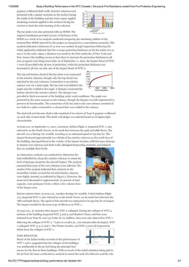
gypsum wallboard shaft walls. Exterior columns were
protected with a plaster material on the surface facing
the inside of the building and also had a spray applied
insulating material applied to the surfaces facing the
exterior to limit the solar heating of the columns.
The bar joists were also protected with an SFRM. The
original installation provided 19 mm of thickness of the
SFRM as a result of an analysis conducted comparing the insulating abilities of the
mineral fiber SFRM selected for the project as compared to a cementitious material. (The
analysis indicated a thickness of 13 mm was needed, though inspections following the
initial application indicated that the average protection thickness on the bar joists was 19
mm.) In the early 1990s, a decision was made by the Port Authority of New York and
New Jersey (the building owner at that time) to increase the protection thickness to 38
mm as spaces were being renovated. As of September 11, 2001, the impact floors of WTC
1 were all provided with 38 mm of protection, while the protection thickness was
increased to 38 mm on only one of the impact floors of WTC 2.
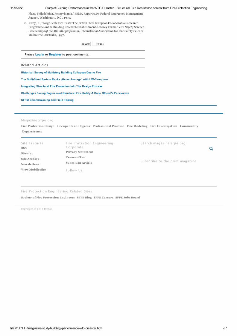
The top and bottom chord of the bar joists were connected
to the exterior columns, though only the top chord was
attached to the core columns. Connection to an exterior
column was via a steel angle. The bar joist was bolted to the
angle and also welded to the angle. A damper connected the
bottom chord to the exterior column. The damper was
provided to limit movement of the building under wind conditions. The angle was
protected in the same manner as the column, though the damper was left unprotected to
preserve its functionality. The connection of the bar joist to the core column consisted of
two bolts to a plate connected to a channel that was welded to the column.
The stairwell and elevator shaft walls consisted of two layers of Type X gypsum wallboard
on each side of steel studs. This shaft wall design was selected based on its lightweight
characteristic.
At 8:46 a.m. on September 11, 2001, American Airlines Flight 11 impacted WTC 1, also
referred to as the North Tower, on its north face between the 94th and 98th floors. The
aircraft was a Boeing 767-200ER, traveling at an estimated speed of 750 km/hr. The
impact fractured approximately two-thirds of the exterior columns on the north face of
the building, damaged floors in the vicinity of the impact location, inflicted some damage
to interior core columns and shaft walls, dislodged fireproofing material, and initiated
fires on multiple floor levels.
An elementary analysis was conducted to determine the
load redistribution along the exterior columns to assess the
level of damage caused by the aircraft impact. The analysis
assumed that none of the core columns were affected. The
results of the analysis indicated that columns in the
immediate vicinity around the severed exterior columns
were highly stressed, as indicated in Figure 3. However, the
stress level decreased to approximately 20 percent of load
capacity, near preimpact levels, within a few column lines
of the impact area.
Sixteen minutes later, at 9:02 a.m., another Boeing 767-200ER, United Airlines Flight
175, impacted WTC 2, also referred to as the South Tower, on its south face between the
78th and 84th floors. The speed of this aircraft was estimated to be 950 km/hr at impact.
The impact resulted in the same type of effects as in WTC 1.
At 9:59 a.m., 57 minutes after impact, WTC 2 collapsed. During the collapse of WTC 2,
sections of the building impacted WTC 3 and 4, and Banker's Trust, and fires were
initiated in 90 West St. and 130 Cedar St. In addition, fires were also observed in WTC 7
following the collapse of WTC 2. 2 Later at 10:28 a.m., 102 minutes after its impact, WTC
1 collapsed. WTC 3, 5, 6, and 7, The Winter Garden, and WFC 3 were all impacted by
debris from the collapse of WTC 1.
FIRE BEHAVIOR
Much of the initial media accounts of the performance of
WTC 1 and 2 suggested that the collapse of the buildings
was attributable to the jet fuel being the principal fuel
source for the fires in these buildings. With so much of the initial attention being paid to
the jet fuel, the team conducted an analysis to assess the early fire behavior and the role

11/9/2556 Study of Building Performance in the WTC Disaster | Structural Fire Resistance content from Fire Protection Engineering
file:///D:/TTP/magazine/study-building-performance-wtc-disaster.htm 4/7
of the jet fuel in WTC 1 and 2.
At impact, each aircraft was estimated to be carrying 38,000 liters of jet fuel. 1 In
addition to being released on the impact floors, the jet fuel was consumed in the fireballs,
flowed down shafts (in some cases igniting in shafts or the concourse of WTC 1, and some
may have flowed down the outside of the building. The amount of jet fuel needed to
support a fireball of a particular size can be estimated from correlations in the literature. 3
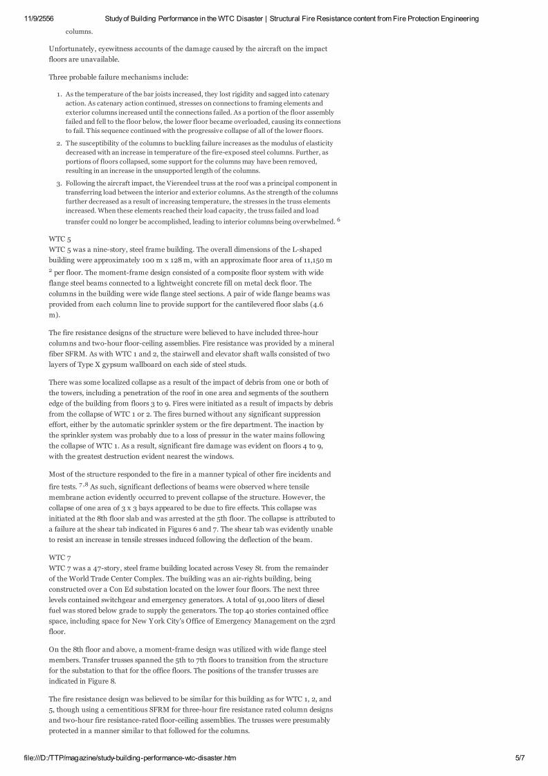
D m =5 25 0 314
where D is the diameter of the fireball (m) and m is the
mass of fuel vapor (kg). The fuel consumed for different
fireball diameters is presented in Figure 4. A photograph of
the fireballs following the impact of WTC 2 is presented in
Figure 5. In Figure 5, the diameter of the fireball from the
north side of WTC 2 appears to be approximately the same
as the length of a side of the building, i.e. 60 to 70 m. Based on the correlation from the
literature, approximately 3,700 liters of jet fuel were consumed in each fireball. Given the
presence of three fireballs, this represents approximately 11,000 liters.
An estimate of the time required for the remaining jet fuel to be consumed was generated
by neglecting any fuel that may have flowed down shafts or otherwise left the impact
floors. An upper limit of the duration of the jet fuel was provided by assuming that the
fuel formed a pool. The mass burning rate for liquid fuels is on the order of 50 g/m 2 -s. 4
Assuming that the fuel spread throughout one floor with an area of 3,980 m 2 , the
duration of burning for the remaining 11,000 liters of jet fuel would be less than one
minute. Actually, the fuel was probably dispersed over the office furnishings present on
the floor (thereby increasing the fuel surface area) and served as an igniter for the mix of
office furnishings present on the impact floors. Some of the jet fuel may also have formed
small pools in sections of wing tanks that survived the effects of the impact. The jet fuel
may have burned in these small sections of the building for several additional minutes.
Consequently, for the majority of the duration that the fires
burned in WTC 1 and 2, the fires involved the office
furnishings present in the buildings. Rehm, et al., at NIST
conducted an analysis of the fire behavior in the towers
using FDS. 5 Their analysis was based on matching the rise
of the smoke plume from videotapes and photographs with
that provided by the computer simulation. Input for the
model involved estimating the size of the hole(s) created by the aircraft impact and
ambient weather data. The size of the holes was estimated based on photographic
evidence. Weather data were reported from three departing aircraft from nearby
LaGuardia and Newark airports between 7:15 a.m. and 9:00 a.m. at heights comparable
to the floor levels of the impact. The wind speeds were 16 to 32 km/hr. and the ambient
temperature was 20C to 21C
The peak heat release rate estimated by Rehm, et al., in the towers was likely to be
approximately 1.0 to 1.5 GW. Temperatures within the floor areas were also predicted to
vary greatly, being as high as 900C to 1,000C in some areas, while being 400C to 800C
in others. This range of temperatures is attributed to the changed geometry and fuel
loading in the space as a result of the aircraft entry into the building. The range in fire
behavior is evident in the photographic evidence where flame projections from openings
are visible in some areas and not others. In addition, in some areas where the exterior
columns and glass remained intact, flames are visible, while in other areas they are not.
As such, the well-stirred reactor view of fully-developed fires does not appear to apply to
this situation.
PROBABLE COLLAPSE MECHANISMS
In both WTC 1 and 2, the collapse of the buildings is
attributed to the combined effects of the damage caused by
the aircraft and the weakening of the steel as a result of the
fire. The damage caused by the aircraft included:
Destruction of some exterior and interior columns, resulting in some of the remaining
columns becoming highly stressed.
Destruction of some portions of the floor framing and slab, at least in the vicinity of the
impact areas. Floor slabs under the collapsed areas were required to support additional
loads associated with the damaged aircraft and thus were more heavily stressed.
The force of the impact and the trajectory of the components of the aircraft through the
space resulted in some dislodgement of fireproofing material from the bar joists and core
11/9/2556 Study of Building Performance in the WTC Disaster | Structural Fire Resistance content from Fire Protection Engineering
file:///D:/TTP/magazine/study-building-performance-wtc-disaster.htm 5/7
Unfortunately, eyewitness accounts of the damage caused by the aircraft on the impact
floors are unavailable.
Three probable failure mechanisms include:
WTC 5
WTC 5 was a nine-story, steel frame building. The overall dimensions of the L-shaped
building were approximately 100 m x 128 m, with an approximate floor area of 11,150 m
2 per floor. The moment-frame design consisted of a composite floor system with wide
flange steel beams connected to a lightweight concrete fill on metal deck floor. The
columns in the building were wide flange steel sections. A pair of wide flange beams was
provided from each column line to provide support for the cantilevered floor slabs (4.6
m).
The fire resistance designs of the structure were believed to have included three-hour
columns and two-hour floor-ceiling assemblies. Fire resistance was provided by a mineral
fiber SFRM. As with WTC 1 and 2, the stairwell and elevator shaft walls consisted of two
layers of Type X gypsum wallboard on each side of steel studs.
There was some localized collapse as a result of the impact of debris from one or both of
the towers, including a penetration of the roof in one area and segments of the southern
edge of the building from floors 3 to 9. Fires were initiated as a result of impacts by debris
from the collapse of WTC 1 or 2. The fires burned without any significant suppression
effort, either by the automatic sprinkler system or the fire department. The inaction by
the sprinkler system was probably due to a loss of pressur in the water mains following
the collapse of WTC 1. As a result, significant fire damage was evident on floors 4 to 9,
with the greatest destruction evident nearest the windows.
Most of the structure responded to the fire in a manner typical of other fire incidents and
fire tests. 7 ,8 As such, significant deflections of beams were observed where tensile
membrane action evidently occurred to prevent collapse of the structure. However, the
collapse of one area of 3 x 3 bays appeared to be due to fire effects. This collapse was
initiated at the 8th floor slab and was arrested at the 5th floor. The collapse is attributed to
a failure at the shear tab indicated in Figures 6 and 7. The shear tab was evidently unable
to resist an increase in tensile stresses induced following the deflection of the beam.
WTC 7
WTC 7 was a 47-story, steel frame building located across Vesey St. from the remainder
of the World Trade Center Complex. The building was an air-rights building, being
constructed over a Con Ed substation located on the lower four floors. The next three
levels contained switchgear and emergency generators. A total of 91,000 liters of diesel
fuel was stored below grade to supply the generators. The top 40 stories contained office
space, including space for New York City's Office of Emergency Management on the 23rd
floor.
On the 8th floor and above, a moment-frame design was utilized with wide flange steel
members. Transfer trusses spanned the 5th to 7th floors to transition from the structure
for the substation to that for the office floors. The positions of the transfer trusses are
indicated in Figure 8.
The fire resistance design was believed to be similar for this building as for WTC 1, 2, and
5, though using a cementitious SFRM for three-hour fire resistance rated column designs
and two-hour fire resistance-rated floor-ceiling assemblies. The trusses were presumably
protected in a manner similar to that followed for the columns.
columns.
1. As the temperature of the bar joists increased, they lost rigidity and sagged into catenary
action. As catenary action continued, stresses on connections to framing elements and
exterior columns increased until the connections failed. As a portion of the floor assembly
failed and fell to the floor below, the lower floor became overloaded, causing its connections
to fail. This sequence continued with the progressive collapse of all of the lower floors.
2. The susceptibility of the columns to buckling failure increases as the modulus of elasticity
decreased with an increase in temperature of the fire-exposed steel columns. Further, as
portions of floors collapsed, some support for the columns may have been removed,
resulting in an increase in the unsupported length of the columns.
3. Following the aircraft impact, the Vierendeel truss at the roof was a principal component in
transferring load between the interior and exterior columns. As the strength of the columns
further decreased as a result of increasing temperature, the stresses in the truss elements
increased. When these elements reached their load capacity, the truss failed and load
transfer could no longer be accomplished, leading to interior columns being overwhelmed. 6

11/9/2556 Study of Building Performance in the WTC Disaster | Structural Fire Resistance content from Fire Protection Engineering
file:///D:/TTP/magazine/study-building-performance-wtc-disaster.htm 6/7
Fires were observed on multiple floors in WTC 7 following the collapse of WTC 2. 2
Photographs of the south face of the building indicate fires were located on many of the
floors. Fire fight-ers report that while the fire appeared on several floors throughout the
day, it appeared to be located on the 6th floor for the entire duration. A camera from the
north of the building recorded light gray, modestly buoyant smoke emanating from the
building throughout much of the day. Approximately one hour before the collapse, the
smoke became dark gray and appeared to be much more buoyant.
At 5:20 p.m., the collapse sequence initiated. First, the penthouse on the east side of the
roof disappears from view, then about 10 seconds later the penthouse on the west side
disappeared. Immediately after the disappearance of the west penthouse, the progressive
collapse started, apparently at a low floor. On the videotape record of the collapse from
the news media, the upper 30 to 35 stories appear to descend intact, indicating the
collapse was initiated on a lower floor. In addition, just prior to collapse, a crack or "kink"
(as referred to in the FEMA report 1 ) becomes evident on the north wall in the vicinity of
the east penthouse.
The east penthouse is located over transfer trusses 1 and 2. One proposed mechanism of
the collapse was a failure of transfer truss 1 or 2 due to fire exposure on that level. Fuel
loads were reportedly light in the vicinity of the trusses except for pipes carrying diesel
fuel to and from the generators. While some fuel was found in the under-ground tanks
once they were recovered, the role of the diesel fuel was questioned by the BPAT.
OTHER OBSERVATIONS
The FEMA report 1 was intended to provide a compilation of the facts, as could be best
accumulated during the seven-month period. The FEMA report did not recommend any
immediate code changes based on the limited analysis conducted in the BPS. Certainly, as
re-search continues to identify probable collapse mechanisms in WTC 1, 2, 5, and 7 as
well as to understand why collapse was arrested in WTC 5, possible recommendations for
code changes could become apparent.
Areas recommended for further study include:
James Milke is with the University of Maryland.
REFERENCES
Are there details of the structural design of WTC 1, 2, 5, and 7 that made them more
susceptible to collapse? Are there subtle changes in the design that could have prevented the
collapse of these buildings?
What is the role of connections in fire-resistant assemblies? Connections are not included in
standard fire resistance tests. Thus, protection of connections is often done simply by
continuing the same protection as for the connected structural member.
Can the durability of fireproofing materials to impact loads be improved?
Critical elements whose failure would lead to progressive collapse need to be identified.
Such is reportedly common practice in the U.K., but not the U.S. Policy needs to be
established on how such critical elements should be protected, i.e., is additional fire
resistance needed, should special inspection programs be established to confirm proper
protection of such elements?
Tools to predict performance of buildings to actual fires need to be developed, including the
role of connections (results from standard fire resistance tests cannot be used to predict
performance). Such tools are needed for conducting performance-based design of structural
fire protection systems and would be essential in providing real-time information for fire
service officers directing emergency operations in high-rise buildings subjected to serious
fires.
1. World Trade Center Building Performance Study: Data Collection, Preliminary
Observations, and Recommendations, FEMA Report 403, Federal Emergency Management
Agency, Washington, D.C., 2002.
2. Smith, D., Report from Ground Zero: The Story of the Rescue Efforts at the World Trade
Center, Putnam Publishing Group, 2002.
3. Zalosh, R., "Explosion Protection," SFPE Handbook of Fire Protection Engineering, 3rd
Edition, P.J. DiNenno, (Ed.), NFPA: Quincy, MA, 2002.
4. Babrauskas, V., "Heat Release Rates," SFPE Handbook of Fire Protection Engineering, 3rd
Edition, P.J. DiNenno, (Ed.), NFPA: Quincy, MA, 2002.
5. Rehm, R., "Modeling Fires In the World Trade Center Towers," Fire Risk & Hazard
Assessment Research Application Symposium, Fire Protection Research Foundation,
Baltimore, MD, 2002.
6. Clifton, G., "Collapse of the World Trade Center Towers," Structures in Fire '02, University
of Canterbury, New Zealand, 2002.
7. Routley, J., Jennings, C., and Chubb, M., "High-Rise Office Building Fire, One Meridian
11/9/2556 Study of Building Performance in the WTC Disaster | Structural Fire Resistance content from Fire Protection Engineering
file:///D:/TTP/magazine/study-building-performance-wtc-disaster.htm 7/7
Site Features
RSS
Sitem ap
Site Archive
Newsletters
View Mobile Site
T witterFacebookLinkedinRSS
Fire Protection Engineering
Corporate
Privacy Statem ent
T erm s of Use
Subm it an Article
Follow Us
Search magazine.sfpe.org
Subscribe to the print magazine
Society of Fire Protection Engineers SFPE Blog SFPE Careers SFPE Jobs Board
Magazine.Sfpe.org
Fire Protection Design Occupants and Egress Professional Practice Fire Modeling Fire Investigation Com m unity
Departm ents
Fire Protection Engineering Related Sites
Copy right © 201 3 Penton
PRINT REPRINTS FAVORITE EMAIL
Tweet
Please Log In or Register to post comments.
Related Articles
Historical Survey of Multistory Building Collapses Due to Fire
The Soffi-Steel System Ranks 'Above Average' with UW-Campuses
Integrating Structural Fire Protection Into The Design Process
Challenges Facing Engineered Structural Fire Safety-A Code Official's Perspective
SFRM Commissioning and Field Testing
Plaza, Philadelphia, Pennsylvania," FEMA Report 049, Federal Emergency Management
Agency. Washington, D.C., 1991.
8. Kirby, B., "Large Scale Fire Tests: The British Steel European Collaborative Research
Programme on the Building Research Establishment 8-storey Frame." Fire Safety Science
Proceedings of the 5th Intl Symposium, International Association for Fire Safety Science,
Melbourne, Australia, 1997.
SHARE